1. Introduction
In this paper, approaches for new design paradigms in liquid deposition modelling (LDM) of clay will be described in three case studies that consider the material, programming (code), and machining holistically in their relational conditions. While previous approaches have placed an emphasis on altering the material properties to enable better reproducibility, new approaches focus on using the material’s existing properties to achieve the final product. The work presented here was conducted by the Department of Visual Arts at the RWTH Aachen University, which explores various materials, including their specific characteristics and performance within the context of architecture.
The liquid material behavior of clay in LDM has been researched experimentally over the past 10 years, primarily in small-scale prototypes, with regard to identically reproducible material properties [
1,
2]. In addition, to avoid process-related deviations, studies have been conducted on structural elements and their optimization in regard to shapes and dimensions [
3,
4]. Furthermore, a comparison with conventional manufacturing processes from the ceramics industry showed that the feasibility of manufacturing larger structural elements and quantities is also being investigated and that the cost factor plays a role [
5]. In fact, it can be assumed that the material behavior of liquid-extruded elements made of clay (or concrete) is difficult to control, and become less controllable with increasing size of the structural elements [
6]. As a result, material-related deviations from the original 3D modeling object inevitably occur in the process of materializing digital models [
7]. Furthermore, 3D modelling software programs, such as Grasshopper plugins, are being further developed to account for these deviations. Developments in the representation of moving or fluid models are rare, and a 1:1 direct simulation of the form changes during the printing process in clay or other liquid materials for 3D modelling software has not yet been fully achieved [
8]. Although the first attempts to implement material behavior and control mechanisms in software were made in the 2010s [
9,
10], designer must continue to rely on their craft skills when dealing with the haptic reality and digitized tools [
11]. Increasingly, experiments focused on exploiting the natural properties of the clay are showing the potential of clay LDM in artistic works [
12,
13], as well as in elements for architectural applications [
14,
15,
16].
Historically, architects have long been concerned with constructive problems of form, as expressed in the 1890s in the reduced clarity of the paradigm “form follows function”. Due to the new material innovations and developing digital processing methods, this guiding principle changed at the beginning of the 21st century into the alliterations “form follows fun” [
17] and “form follows flow” [
18]. These changes show a tendency towards dealing with dynamic systems, the movement of material, and the concept of emergence.
This manuscript is dedicated to the liquid behavior of clay and its design parameters in LDM. We assumed a basic knowledge of the amorphous material that is clay, its drying and shrinkage behavior, as well as knowledge of the necessary firing process [
19]. From a detailed material view, the fluid behavior of the material, which is required for the process, should not be regarded as an unavoidable evil that is covered up with technical tricks and chemical additives. Rather, the liquid and dynamic properties of clay during the LDM should be understood and implemented during the conceptual handling stage. The systematization of new methods for additive forming processes takes place for potential building applications. Just as in the craft process the manageability of the material has been tested for millennia in order to successively refine processing methods, sequences, and tools, the value in the present article also lies in the confrontation of material-typical inherent dynamics and the programmed action of the machine. This article is not intended—as has often been the case—to deal with material science investigations to improve the material itself (e.g., properties of flow) or the technical execution of setting parameters (e.g., layer height (h), feed rate (f), extrusion rate (e), etc.) of the machine.
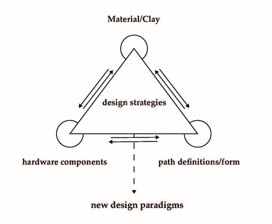
Three case studies are presented below that combine and at least partially systematize the interactions of the material phenomena, code, and machine in the formation of the structure in LDM.
2. Materials and Methods
As an exploratory investigation of form and material phenomena during the LDM of clay, this research was conducted within a defined experimental field. The experimental field is determined by the possibilities of the material and the available machine (e.g., installation space of the printer, extruder with double connecting rods, etc.). This results in dynamic interactions in which the regularly abstract digital model and the (‘externally programmed’) action of the machine meet the deviating particularity of the material, from which a structure emerges. The tailoring of the design parameters is crucial for the shaping in LDM. In this paper, we describe this as ‘setting’. It is not the digital model alone, but the setting as a whole that determines the shape of the resulting artefacts.
For better comparability of play within designed settings, simple geometric hollow shapes (cylinders and cuboids) were assumed in the materialization. In the systematization, artefacts were not excluded due to lack of reproducibility. Instead, these artefacts show the spectrum of customization and variability. In the experimental field, the complex conditions of concrete building applications were not addressed [
20]. Establishing the framework of investigation made it possible to begin to order the discovered phenomena, to expand our understanding of the process-related interrelationships of combined features, and to discover new possibilities for the shaping process. A new perspective on designing with digital media was established.
The clay body used was commercially prepared and pre-packed with homogeneous grain size build-up. To prepare the material for 3D printing, it was mixed with water to a process-relevant viscosity. The variation of clay body types and viscosities was not the focus of this investigation, because studies already exist in this area. The researchers were looking for new correlations and phenomena that have received little attention so far. The case studies were carried out with a WASP40100 3D clay printer (Massa Lombarda, Italy) (
Figure 1). This is a delta printer that moves the extruder and nozzle via three double connecting rods. The soft material is fed in via a clay tank operated with compressed air and extruded via the nozzle. In some cases, expanding tools were developed for the 3D clay printer and were printed as prototypes in PLA using a common filament printer or implemented manually in the form of cut metal components. The program Grasshopper (Rhino 6) and a self-programmed environments with JavaScript were used for the investigation. Within the programs, the conversion to a file readable by the 3D clay printer (G-CODE) was also carried out. In some cases, the text form of the G-CODE was also changed manually.
3. Case Studies
In three exemplary case studies, different settings were developed for the LDM of clay. The various shaping processes arising from the interactions of hybrid (digital + physical) parametric design parameters (digital model, mechanics of the machine, toolpath instruction and dynamic-deviant material behavior) were investigated for the developed settings. In recent years, an increasing number of studies have focused on the generation of comparatively simple material effects in LDM through changes in machine or software settings. These include setting variables such as the layer height (h), print speed/feed rate (f), extrusion rate (e)/flow, and compressor pressure [
21,
22]. Different manufacturers [
23] and researchers [
11] have also attempted to develop hybrid formats in which the possibility manual intervention is included at the end of the process. In addition, initial studies have already looked at real-time feedback systems and sensor technology in the LDM of clay, but these processes are still immature [
24]. For the reasons mentioned above, the case studies use differentiated printing parameters but avoid manual intervention during the 3D printing process and sensor technology for interactive shape corrections. The phenomena discussed here were partly developed within the experimental field due to unforeseeable process- or material-related “programmed disasters”. The final product within in the experimental field resulted from a series of digitally (pre-)programmed path instructions and processing steps of the machine. The feedback of the programming performance only arises within the 3D printing process, during the materialization of the digitally written artefacts.
The Case study 3.1, ‘material behavior of clay’, focuses on the dynamic properties of the clay body in combination with the programmed, mechanical processing technology of the machine. Case study 3.2, ‘nozzle as a tool’, focuses on the use of customized hardware components in combination with complex path instructions. It describes the possibility of splitting path instructions for the additive build-up of material layers and pure tool instructions for the deformation or removal of material. Case study 3.3, ‘non-horizontal layering’, focuses on the path definition with regards to the combination of material characteristics and machine parameters. These studies are intended to be regarded as examples in order to give an idea of the multidimensionality of this methodological playing field, which effectively enables an infinite number of variations.
In case studies 3.1 and 3.2, the chosen geometry for 3D printing was a hollow, single-walled cylinder. In order to limit the factor ‘direction of fall of the material’, a hollow, single-walled cuboid was implemented in case study 3.3. Single-walled, unfilled forms facilitate the drying and firing process, requiring low material input while maintaining good static performance.
3.1. Material Behavior of Clay
This case study illustrates specific peculiarities of clay in contrast to the fused deposition modelling (FDM) of plastics. Unlike plastics, clay proves to be ‘imperfect’ with regards to its reaction to programmed path instructions. Here, we regularly observe the phenomenon of a ‘potentiating catastrophe’, indicating deviation from the abstract plan. The fused deposition modelling (FDM) of filaments currently is suitable for everyday use. Here, the assumption is correct that the material can be applied with pinpoint accuracy and remains where the machine has positioned it [
25]. Of course, there are also material effects in FDM that are related to the way the material is applied [
26], but these are not comparable to the deviations in LDM. The material changes its position after being ejected from the nozzle of the 3D printer due to flow behavior, gravity, and the deposition or printing direction of the nozzle.
3.1.1. Printing into Previous Layers
In different experiments, it was observed that the digital model, the visualized idea in the form of a print path, does not match the results of the printed artefacts.
Table 1 (
Appendix A) shows a comparison of the modelled path instruction and materialized implementation in clay. Material phenomena can be observed due to the plasticity of clay in connection with gravitation. Furthermore, due to its softness, the layers of clay can more easily be ‘printed into each other’ [
27] and produce a change in the printing progress benefiting the planned surface.
3.1.2. Second-Row Material Deposition
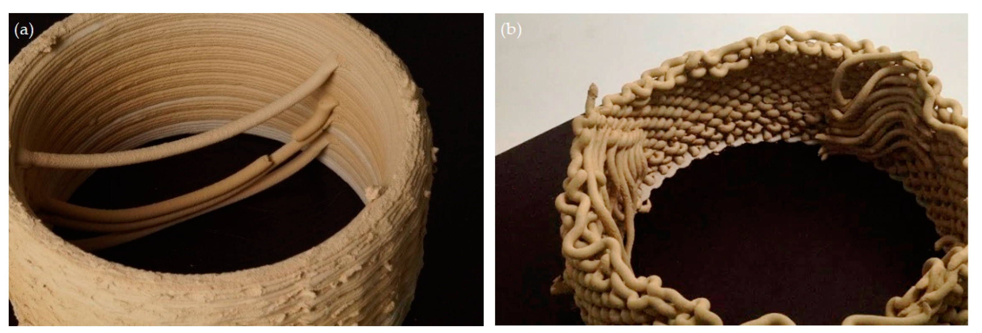
Within the case study, the phenomenon of ‘second-row material deposition’ (
Figure 2a,b) was also examined. Depending on the printing parameters of the artefact, even a single-walled path instruction in the LDM can generate an additional material pattern. The effect is created by varying the already well-described printing parameters (layer height (h), print speed/feed rate (f), extrusion rate (e)/flow) in combination with programmed path instructions, the movement of the nozzle, as well as the radius of the overall artefact. The effect is influenced by the adhesion properties of the material. If the extruded material sticks more strongly to the printer nozzle and rolls off the built-up artefact, the material is carried away across the tool path. It deposits itself with a bizarre regularity and as an additional pattern at the next possible position on the artefact.
In the field of media philosophy, Beatrice Fazi also talks about ‘digital aesthetics’ as an expression of the ‘unpredictability’ of programmed code [
28]. However, it is not only algorithmic programming that is perceived by designers as an ‘unpredictable moment’, but also the process of materialization that the designer has handed over to the machine via programming. The settings ‘printing into previous layers’ and ‘second-row material deposition’ constructed in this case study address the material and its specific properties as the starting points for the combinations of characteristics of differentiated process parameters and control variables.
3.2. Nozzle As a Tool
Within the case study ‘nozzle ass tool’, the starting point was the examination of the hardware of the 3D clay printer and its tools in combination with the material behavior and programmed path instructions. We are not currently aware of any hardware-based add-on modules for the WASP40100. However, experiments in 3D printing of liquid materials using different nozzle diameters and geometries [
29,
30], as well as the application of different add-on modules in the field of construction robotics [
31,
32], are known.
The tools developed in this study (
Figure 3a,b) deform the soft material through different material stencils and additional tools in combination with complex path instructions during and after material deposition. The developed tools were used to deform the material during the printing process or to remove it afterwards. Due to its softness, the material allows a combination of additive and subtractive methods. To be able to combine both processes, the path instruction had to be programmed in such a way that the material deposition path and the tool paths executed different instructions. The path instruction for the material separation contains the information for the extrusion (material extrusion path), whereas the path instruction for the tool (tool path) only contains the shaping or driving instructions for the nozzle. The path instructions were programmed so that the machine first built up several layers of material (height and number of layers are adapted to the respective tool) according to the material extrusion path. Subsequently, the respective section was post-processed with a self-developed nozzle according to the tool path.
3.2.1. Nozzle and Complex Extrusion
The shape of the nozzle or the material stencils plays a decisive role in the creation of additive artefacts in clay. Standardized nozzles with round stencils are used as components for the WASP40100. In order to avoid air inclusions and the associated flaking in the fired ceramic, this nozzle shape makes sense. In the setting ‘nozzle and complex extrusion’, systematic investigations were undertaken with different self-developed nozzles and various material stencils for materialized artefacts and combined with partly complex path instructions. A complex extrusion can be observed, for example in the combination of the components of the star-shaped material stencil opening of the nozzle with complex path instructions oscillating in the Z-direction (
Table 2,
Appendix A). In this experiment, a complex and dimensionally stable surface structure was created.
3.2.2. Nozzle, Simple Horizontal Extrusion, and Complex Shape
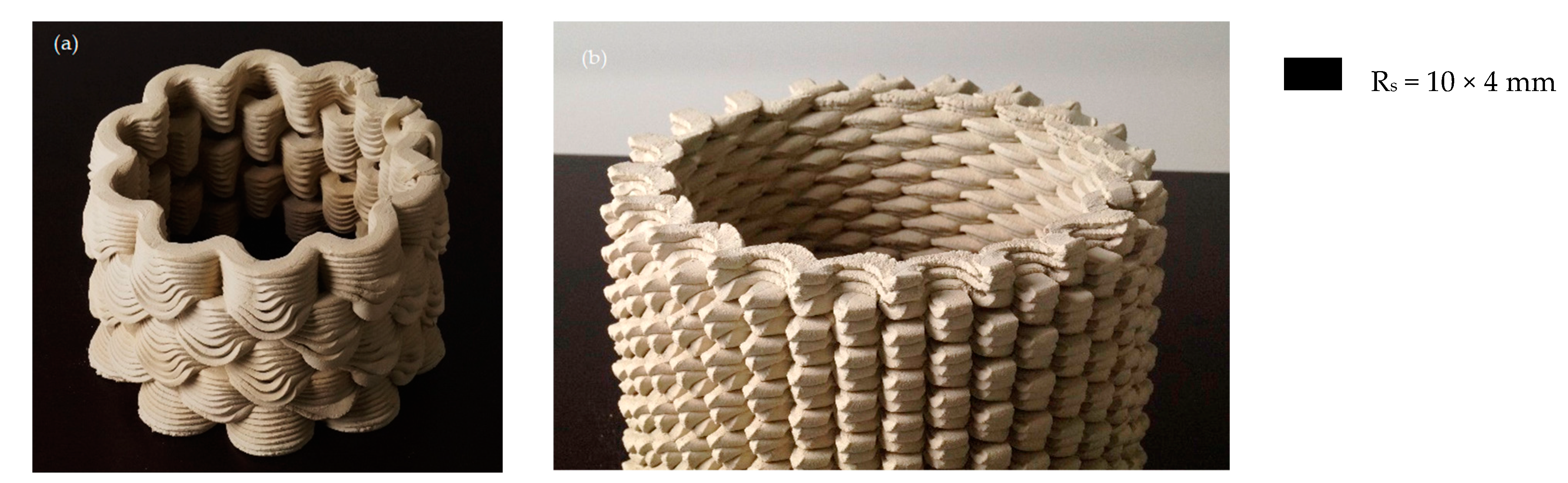
Experience shows that a ‘two-sided look’ in geometry occurs when the material extrusion paths that form the artefact have different shape characteristics on the inside and outside, e.g., convex or concave (
Figure 4a,b). The artefacts created in the ‘nozzle, single horizontal extrusion and complex shape’ setting were produced using a nozzle with a rectangular material stencil and in combination with complex shape paths, resulting in a complex and dimensionally stable surface structure.
3.2.3. Nozzle, Simple Horizontal Extrusion, and Tool Instruction Offset
In the setting ‘nozzle, simple horizontal extrusion, and tool instruction offset’ phase, a square material stencil of the nozzle was combined with simple material extrusion paths and additional tool path information. Using the additional tool path information, the nozzle subsequently pushed a programmed pattern into the previously deposited material (
Table 3,
Appendix A).
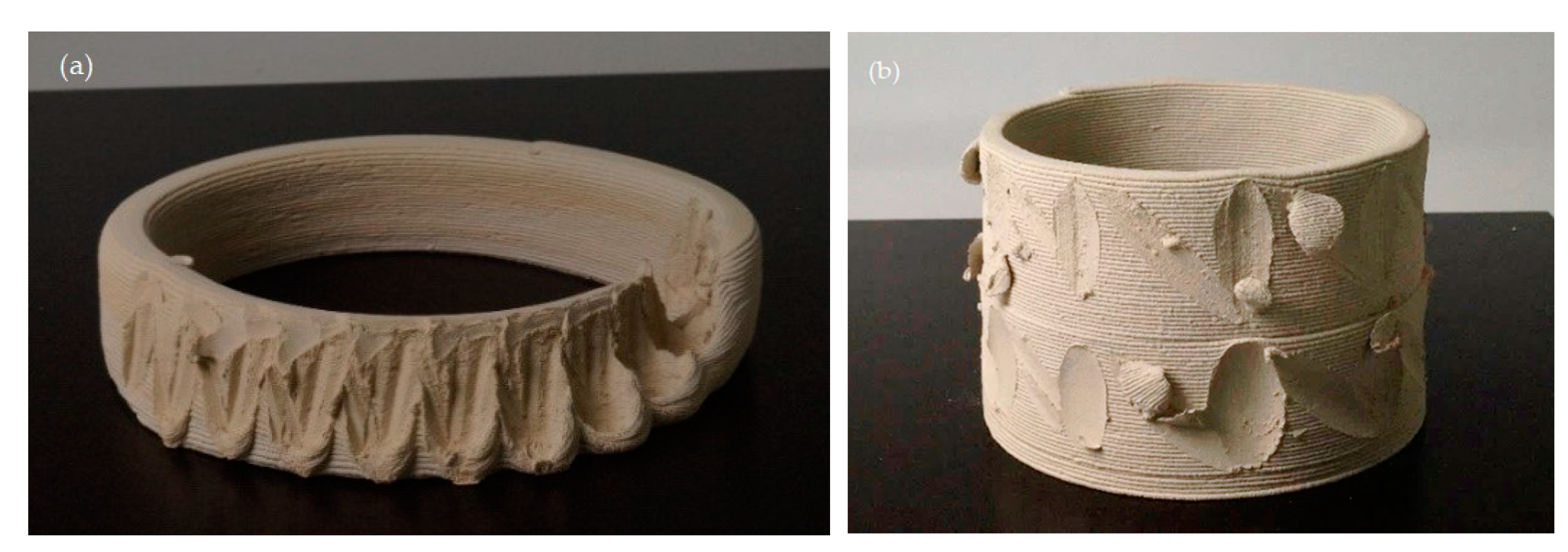
Through the combination of complex path instructions (pushing the cylinder in at regular intervals) and the circular material extrusion, the shape changes to a corrugated cylinder. By applying these combinations of features, the additively produced artefact was subsequently ‘pushed open’. It can be seen that the deforming of the artefact reduces further over the course of the project. Since the artefact is not filled with material, the structure becomes more flexible and its overall geometry cannot offer material resistance to the tool. Due to the adhesion to the printing plate, the lower layers can be deformed particularly well.
3.2.4. Nozzle, Simple Horizontal Extrusion, and Tool Instruction Stamp
The example
Table 4 (
Appendix A)shows the result of the tool processing following the extrusion of the clay layers. The additional tool used here was mounted rotatably on a standard nozzle (Ø = 8 mm). After some printed material layers (height and number of layers depend on the size of the additional tool), the path instruction ‘extrusion’ changed to the path instruction ‘stamp tool’. Here, the nozzle drove around the already printed material layers with the tool and printed a defined pattern into the artefact. Here, the ‘two-sided look’ is created by using the simple horizontal extrusion and tool path statement parameters for the rotatable additional tool.
3.2.6. Nozzle, Simple Horizontal Extrusion, and Tool Instruction Material Removal
The ‘nozzle, simple horizontal extrusion, and tool application material removal’ parameters dealt with the combination of the processes of additive and subtractive methods in a print instruction. Similarly to the complex tooling instructions described earlier, the application and removal process steps alternate. The concept was tested with movable and immovable cutting tools. The geometry of the respective cutting tools was rotationally symmetrical, because the nozzle does not have its own axis of rotation. Complex tools also make the programming of tool path instructions more complex (
Table 6,
Appendix A).
The different cutting tools quickly became dirty during the subtractive process step and the cut clay residues fell randomly into the print space when touched or remained stuck to the artefact (
Figure 6). The softness of the material, which is necessary for additive application with the 3D clay printer, is less suitable for material removal processes. Ideally, a time delay would be introduced between the application and removal processes. However, this was not possible in the designed settings due to the alternating nature of the application and removal process steps and the dimensions of the machine.
Pattern formation for the tactile perception of 3D-printed objects has been a topic for some time [
33]. Similar to the investigations into the setting sizes of print parameters in LDM, these phenomena are primarily concerned with variations in the programmable material extrusion paths (
Table 2). The significance of the ‘nozzle as a tool’ case study was the combination of material extrusion paths and additional tool path information with different components. The additional tools were produced by the authors on the basis of prior experience.
The machine (3D clay printer) and its dimensions determine the shape-forming settings. The extruder is mounted on a plate with three double connecting rods, so that the dimensions become relevant in descending path instructions, as already extruded artefacts can be destroyed in the process; in addition, the standard nozzles of the 3D clay printer are only a few centimeters long, so that the adapter or chuck of the extruder is quickly reached (
Figure 5a). Finally, the nozzle of the 3D clay printer can only extrude perpendicular to the printing plane (3-axis) and cannot be tilted, as would be possible with robot arms (5- or 6-axis). The dimensions of the machines and the lack of mobility in the nozzle area, thus, determine the possible shaping processes both in terms of form and space.
3.3. Non-Horizontal Layering
As previously described, the machine used determines the experiments due to its dimensions and the rigid vertical orientation of the nozzle. As a result, a lot of ‘friction’ arose in the ‘non-horizontal layering’ series of experiments, in which complex material extrusion paths were designed with the material behavior of clay and with its specifics in mind (
Figure 7).
The LDM process has so far been viewed from the traditional, technical–constructive approach of horizontal layer build-up without much questioning in the professional world. Exciting studies that rediscover the aspect of material application exist, for example, in the robotic 3D printing of metal [
34] or in the application of synthetic composites and fabrics that may receive reinforcement with construction resins [
35]. Presumably, the additional rotation axis of the robot inspired the researchers in these studies to create such free-form structures. However, current experiments with earths and concrete also show that additive components can be produced beyond the traditional shell or dome structures made of clay or bricks [
36]. The direction of pressure corresponds to the path of the forces, whereby the material supports itself layer-by-layer. A ‘non-horizontal layering’ approach can create completely new structural elements (
Table 7,
Figure 8a,b and
Figure 9a,b).
Figure 7.
Generation of arc geometry I (
Table 8) with complex path instruction (material extrusion + tool) as ‘non-horizontal layering’ in the LDM of clay.
Figure 7.
Generation of arc geometry I (
Table 8) with complex path instruction (material extrusion + tool) as ‘non-horizontal layering’ in the LDM of clay.
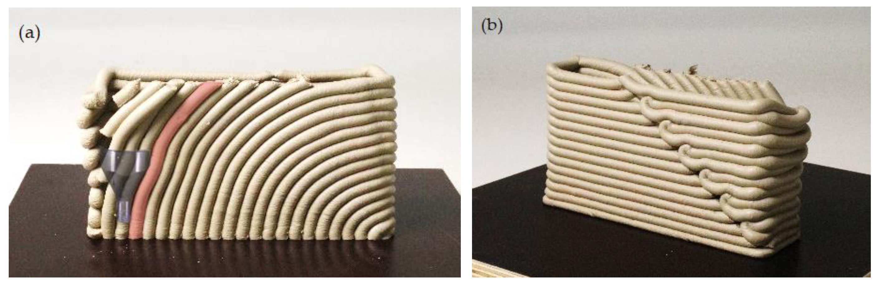
3.3.1. Self-Support of the Material
Figure 8a shows non-horizontal layering following the geometry of a half-arch (arch geometry I). In this configuration, the material can support itself. The wall built-up along the arc geometry is supplemented by three traditionally horizontally layered walls that support the front side. On the one hand, this allows the combination of layering systems to be tested (
Figure 8b), while on the other hand the non-horizontally layered wall is supported by the other structures. This does not mean that a non-horizontally layered wall is less stable than a horizontally layered wall. In initial materialization experiments, it became clear that the pressure path required different printing parameters in the vertical and horizontal directions. In the vertical direction, the material can be printed side-by-side without deformations, while in the horizontal direction the material has to be printed somewhat ‘inside the previous layer’, otherwise the individual layers do not adhere sufficiently to each other and the artefact deforms too much, which in turn means that the following material application no longer matches the position of the artefact. It also became clear that contiguous material precipitates were more effective at improving the accuracy of fit of the artefact (cf.
Figure 8b) than small interrupted material precipitates (cf.
Figure 8a, top left). In addition, the impacts of the machine dimensions were clearly visible in the artefacts.
Figure 8a shows the imprint of the nozzle in a perfectly curved material extrusion path (red).
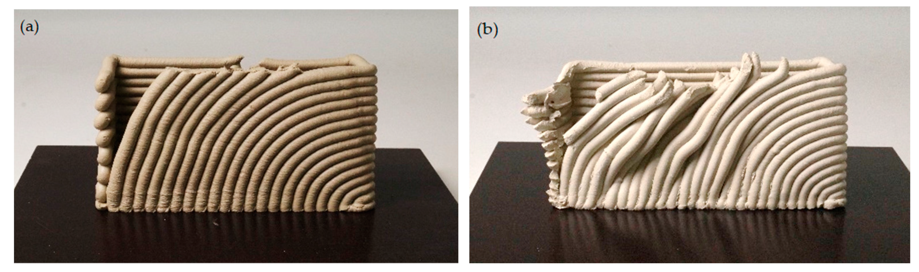
3.3.2. Direction of Extrusion
A further development in the form of arc geometry II also allowed experimentation with the direction of the material extrusion. The double arcs on the front side of arc geometry II (
Figure 9a) were programmed so that the material was applied from the bottom to the top, so that it could support itself in both cases. On the back of arc geometry II (
Figure 9b), the nozzle travelled the material extrusion path from top to bottom, virtually pushing the material forwards. This production direction from top to bottom also worked but had its limitations, as
Table 9 shows. The cuboids produced here and laid out as closed material extrusion paths each show different layering in the transverse direction and contrast the limits of this path instruction.
3.3.3. Wipe of Material
In arc geometry I, the last ‘layers’ were cut off as unfinished arcs. This is largely due to the machine dimensions, which determine the height of the geometry, but provides an opportunity to address the phenomenon of ‘wiping material’. The material is always pulled in the direction in which the tool moves next in the sequence of the path instruction.
Figure 10a,b demonstrate the ‘wiping of material’ effects.
Figure 10a shows the ‘wiping of material’ in the direction of the arc geometry, while
Figure 10b shows the exact opposite. If the tool path or movement follows the material extrusion path without further extruding the material, the material is deposited cleanly. If the direction of the tool path is made in the opposite direction, the clay body will stick to the nozzle and drag the previously extruded material with it (
Figure 10b).
Understanding the ‘self-support of the material’, ‘direction of extrusion‘, and ‘wiping of material’ phenomena opens up new possibilities for shape formation. Closed-path instruction enabled stable surface structures that also functioned in different material extrusion directions. The machine and tools used determine the respective settings and the material accounts for variations in the different artefacts.
4. Conclusions
In the three case studies presented here, it was possible to show which potentials can be expected by combining the features of dynamic material behavior and abstract, regular execution of the machine.
The LDM of clay offers a wide spectrum of currently unexploited possibilities for shape generation with a variety of design parameters, which could be of interest for creative disciplines such as architecture and design. Only a selection of parameters and their possible combinations could be examined in this paper. Material investigations that illuminate the spectrum of transformative material properties from soft to hard, for example, could not be undertaken here, although they also open up potentials for material-appropriate design formation. Transferability to other fluid construction materials is not ruled out by the authors, but has not been investigated in detail. It became apparent in all three case studies that the machine parameters, dimensions, and tools play a major role in the production of artefacts from clay. Similarly, the programming of path instructions for combinatorial processes is relatively complex and needs to be considered and laid out in advance for the settings described. During the LDM, the designer has no design-forming intervention options, except for a general ‘abort’ instruction. Closed-path instructions, such as cylindrical shapes, fundamentally improve print quality and simplify downstream processes, such as subtractive material removal. Further developments in 3D modelling software are to be expected. The authors would recommend that further research be conducted in the area of reactive controllability during the printing process (e.g., via sensor technology). Likewise, any extension of the machine components, such as an additional rotation or tilting axis of the nozzle, would expand the design-forming options.
On the basis of many experiments, some of which are presented here, the authors are of the opinion that the interaction of material-specific behavior patterns and abstract, non-interactive mechanisms of digital modelling with the machine, which act according to their own rules, can be used to establish new design models in the future. In this way—according to the objective—the resulting design formations can also tie in with historically evolved craft traditions as ‘materially appropriate’ artefacts, which can be developed further with new options for shaping and production. In addition to the definition of the abstract geometric concepts, the interacting design parameters of digital modelling, tools, machines, and material processing are decisive in the generation of shapes. The highly complex interactions of all digital and physical parameters can serve as the basis for new design paradigms.
This means that among other things, each individual artefact generated in this way becomes a unique object, having formed itself as a product of the complex action mechanisms. This happens as a dynamic interaction in which the self-programmed, abstract digital model and the (at least partially externally programmed) action of the machine meet the varying properties of the material, giving rise to the final shape. The authors consider the tailoring of these parameters as crucial for shaping in LDM. They have been described here as a setting. It should be emphasized that it is not the digital model alone but the setting as a whole that determines the shape of the resulting artefacts. Of course, this also results in a new understanding of the design process, which cannot be limited exclusively to the digital model (form idea) and is only one determining factor among many. Rather, the setting is designed as the sum of parameters that have an effect, out of which the shape is formed in the end seemingly ‘as if by itself’. Within constructed settings, the formation of generation takes place as a complex, indirectly controllable, interactive interplay of digital, automatic, mechanical, and physical parameters. Their performative materialization is ultimately experienced by the designer who conceived this process as a spectator.
The potentials of the feature combinations of material, code, and machine aspects are still far from being sufficiently investigated. The studies presented here are considered by the authors to be merely exemplary. However, they illustrate the multidimensionality of a methodological playing field that opens up an infinite number of variations and new design paradigms.
Author Contributions
Conceptualization, C.K. and T.H.S.; methodology, C.K. and T.H.S.; software, C.K.; validation, T.H.S.; formal analysis, C.K.; investigation, C.K.; resources, T.H.S.; data curation, C.K.; writing—original draft preparation, C.K.; writing—review and editing, T.H.S.; visualization, C.K.; supervision, T.H.S.; project administration, C.K.; funding acquisition, C.K. All authors have read and agreed to the published version of the manuscript.
Funding
This research received no external funding.
Institutional Review Board Statement
Not applicable.
Informed Consent Statement
Not applicable.
Data Availability Statement
The study does not report any data.
Acknowledgments
Sincere thanks go out to the students involved in the three case studies: Vesela Tabakova (Architecture), Felix Hüning (Architecture), and Jakob Yanagibashi (Computer Science).
Conflicts of Interest
The authors declare no conflict of interest.
Appendix A
| HL—layer height |
| E—extrusion rate/flow |
| F—speed/feed rate |
| Rcyl—cylinder radius |
| Hcyl—cylinder height |
| Rn—nozzle radius |
| Rs—nozzle section |
| 3.1 Material Behavior of Clay |
| Npc—number of points on the circle curves |
| Z-Move Pattern—Binary pattern that sets which points will be moved along the Z-axis |
| Z-Amp.—amplitude of point movement along the Z-axis |
| 3.2 Nozzle as Tool |
| Nsl—number of slanted lines that become ‘zig-zag’ lines |
| Hsl—height of slanted lines |
| Npl—number of points on slanted lines that are to be moved along a tangent |
| T-Amp.—amplitude of point movement along a tangent |
| 3.3 Non-Horizontal Layering |
| Nps—number of single printed segments, which are further processed with a tool |
| Hps—height of single printed segments |
| Dimp—imprint depth of the tool |
| Rt—tool radius |
References
- Peters, B. Building Bytes: 3D-Printed Bricks: Combining a traditional building material (ceramics) with a new fabrication technique (3D printing) to rethink an ancient building component (bricks), the Building Bytes project demonstrates how 3D printers can become portable, inexpensive brick factories for large-scale construction. In Fabricate—Negotiating Design and Making; Gramazio, F., Kohler, M., Langenberg, S., Eds.; gta Verlag: Zürich, Switzerland, 2015; pp. 113–119. ISBN 978-3-85676-331-2. [Google Scholar]
- Keep, J. Formulating and Testing a Clay Body for Extrusion Clay 3D Printing. 2020. Available online: http://www.keep-art.co.uk/Journal/Test_FormulatingClayBody.pdf (accessed on 10 January 2022).
- Cruz, P.J.S.; Knaack, U.; Figueiredo, B.; de Witte, D. Ceramic 3D printing: The future of brick architecture. In Proceedings of the IASS Annual Symposium 2017—Interfaces: Architecture. Engineering. Science, Hamburg, Germany, 25–28 September 2017; Bögle, A., Grohmann, M., Eds.; HafenCity University Hamburg, International Association of Shell & Spatial Structures (IASS): Hamburg, Germany, 2017; pp. 1–10. [Google Scholar]
- Seibold, Z.; Hinz, K.; García del Castillo y López, J.L.; Martínez Alonso, N.; Mhatre, S.; Bechthold, M. Ceramic Morphologies, Precision and Control in Paste-Based Additive Manufacturing. In ACADIA 2018: Recalibration. On Imprecisionand Infidelity, Proceedings of the 38th Annual Conference of the Association for Computer Aided Design in Architecture, Mexico City, Mexico, 18–20 October 2018; Anzalone, P., Del Signore, M., Wit, A.J., Eds.; Association for Computer Aided Design in Architecture (ACADIA), by the Universidad Iberoamericana: Mexico City, Mexico, 2018; pp. 350–357. ISBN 978-0-692-17729-7. [Google Scholar]
- Bechthold, M. Ceramic Prototypes—Design, Computation, and Digital Fabrication. Inf. De La Construcción 2016, 68, e167. [Google Scholar] [CrossRef] [Green Version]
- Teizer, J.; Blickle, A.; King, T.; Leitzbach, O.; Guenther, D. Large Scale 3D Printing of Complex Geometric Shapes in Construction. In Proceedings of the 33rd International Symposium on Automation and Robotics in Construction (ISARC), International Association for Automation and Robotics in Construction (IAARC), Auburn, AL, USA, 18–21 July 2016; pp. 948–956. [Google Scholar] [CrossRef] [Green Version]
- Shi, J.; Cho, Y.; Taylor, M.; Correa, D. Guiding Instability: A craft-based approach for modular 3D clay printed masonry screen screen units. In Architecture in the Age of the 4th Industrial Revolution, Proceedings of the 37th eCAADe and 23rd SIGraDi Conference, Porto, Portugal, 11–13 September 2019; Pedro Sousa, J., Castro Henriques, G., Pedro Xavier, J., Eds.; Blucher: São Paulo, Brazil, 2019; pp. 477–484. [Google Scholar] [CrossRef]
- Payne, A.O.; Johnson, J.K. Firefly: Interactive Prototypes for Architectural Design. Archit. Des. 2013, 83, 144–147. [Google Scholar] [CrossRef]
- Smith, R.T.; Thomas, B.H.; Piekarski, W. Digital foam interaction techniques for 3D modeling. In Proceedings of the 2008 ACM Symposium on Virtual Reality Software and Technology—VRST 08, New York, NY, USA, 27–29 October 2008; p. 61. [Google Scholar] [CrossRef] [Green Version]
- Chaudhury, S.; Chaudhuri, S. Volume preserving haptic pottery. In Proceedings of the 2014 IEEE Haptics Symposium (HAPTICS 2014), Houston, TX, USA, 23–26 February 2014; O’Malley, M., Ed.; IEEE: Piscataway, NJ, USA, 2014; pp. 129–134. [Google Scholar] [CrossRef]
- Mansoori, M.; Kalantar, N.; Palmer, W. Handmade by Machine: A Study on Layered Paste Deposition Methods in 3D Printing Geometric Sculptures. In Proceedings of the Conference Fabrication and Sculpting Event (FASE) 2018At: Instituto Superior Técnico, Lisbon, Portugal, 6–8 June 2018. [Google Scholar]
- Fratello, V.S.; Rael, R. Innovating Materials for Large Scale Additive Manufacturing: Salt, Soil, Cement and Chardonnay. Cem. Concr. Res. 2020, 134, 106097. [Google Scholar] [CrossRef]
- Mäkelä, M. Ceramics and its Dimensions: Shaping the Future—Northern Ireland; Aalto University School of Arts, Design and Architecture: Helsinki, Finland, 2017. [Google Scholar]
- Rosenwasser, D.; Mantell, S.; Sabin, J.E. Clay Non-Wovens: Robotic Fabrication and Digital Ceramics. In Proceedings of the 37th Annual Conference of the Association for Computer Aided Design in Architecture: Massachusetts Institute of Technology, School of Architecture + Planning, Department of Architecture, Association for Computer Aided Design in Architecture (ACADIA), Cambridge, MA, USA, 2–4 November 2017; pp. 502–511. [Google Scholar]
- AlOthman, S.; Im, H.C.; Jung, F.; Bechthold, M. Spatial Print Trajectory: Controlling Material Behavior with Print Speed, Feed Rate, and Complex Print Path. In Robotic Fabrication in Architecture, Art and Design 2018; Willmann, J., Block, P., Hutter, M., Byrne, K., Schork, T., Eds.; Springer International Publishing: Cham, Switzerland, 2019; pp. 167–180. [Google Scholar]
- Ko, M.; Shin, D.; Ahn, H.; Park, H. InFormed Ceramics: Multi-axis Clay 3D Printing on Freeform Molds. In Robotic Fabrication in Architecture, Art and Design 2018; Willmann, J., Block, P., Hutter, M., Byrne, K., Schork, T., Eds.; Springer International Publishing: Cham, Switzerland, 2019; pp. 297–308. [Google Scholar]
- Wachs, M.-E. Material Mind: Neue Materialien in Design, Kunst und Architektur; Kovač: Hamburg, Germany, 2008. [Google Scholar]
- Mogas Soldevila, L.; Duro Royo, J.; Oxman, N. FORM FOLLOWS FLOW: A Material-driven Computational Workflow for Digital Fabrication of Large-Scale Hierarchically Structured Objects. In Proceedings of the 35th Annual Conference of the Association for Computer Aided Design in Architecture, Association for Computer Aided Design in Architecture (ACADIA), Cincinnati, OH, USA, 19–25 October 2015. [Google Scholar]
- Klug, C.; Meyer, J. Meta-Ton. Digitales Gestalten im Spannungsfeld von abstrakter Berechenbarkeit und materialspezifischem Erfahrungswissen. In Wolkenkuckucksheim: Internationale Zeitschrift für Theorie und Wissenschaft der Architektur = Cloud-Cuckoo-Land = Vozdušnyj Zamok; Technische Universität: Berlin, Germany, 2021; pp. 129–144. [Google Scholar]
- Ballestrem, M. Experimentelles Entwerfen: Methoden des kontrollierten Kontrollverlusts. In Media Agency—Neue Ansätze zur Medialität in der Architektur; Barlieb, C., Gasperoni, L., Eds.; Transcript Verlag: Bielefeld, Germany, 2020; pp. 145–160. ISBN 978-3-8376-4874-4. [Google Scholar]
- Rael, R. Printing Architecture: Innovative Recipes for 3D Printing; Princeton Architectural Press: New York, NY, USA, 2018. [Google Scholar]
- Kontovourkis, O.; Tryfonos, G. Integrating Parametric Design with Robotic Additive Manufacturing for 3D Clay Printing: An Experimental Study. In Proceedings of the 35th International Symposium on Automation and Robotics in Construction (ISARC), International Association for Automation and Robotics in Construction (IAARC), Berlin, Germany, 20–25 July 2018. [Google Scholar] [CrossRef]
- Vormvrij. Portrait with Black Clay. Available online: https://vormvrij.nl/lutum/projects/ (accessed on 6 December 2021).
- Bilotti, J.; Norman, B.; Rosenwasser, D.; Leo Liu, J.; Sabin, J.E. ROBOSENSE 2.0: Robotic Sensing and Architectural Ceramic Fabrication. In Proceedings of the 38th Annual Conference of the Association for Computer Aided Design in Architecture (ACADIA), Mexico City, Mexico, 18–20 October 2018; pp. 276–285. [Google Scholar]
- Hoskins, S. 3D Printing for Artists, Designers and Makers; Bloomsbury Visual Arts An imprint of Bloomsbury Publishing Plc: New York, NY, USA, 2018; ISBN 978-1-4742-4872-3. [Google Scholar]
- Cannaerts, C. Hacking Agency: Digitale Fabrikation als Entwurfsmedium. In Media Agency—Neue Ansätze zur Medialität in der Architektur; Barlieb, C., Gasperoni, L., Eds.; Transcript Verlag: Bielefeld, Germany, 2020; pp. 179–196. [Google Scholar]
- Farahbakhsh, M.; Kalantar, N.; Rybkowski, Z. Impact of Robotic 3D Printing Process Parameters on Bond Strength: A Systematic Analysis Using Clay-Based Materials. In Proceedings of the ACADIA 2020 Conference 2021, online, 24–30 October 2020; pp. 594–603. [Google Scholar]
- Fazi, B. Digitale Ästhetik: Das Diskrete und das Kontinuierliche. Int. Jahrb. Für Medien. 2020, 6, 219–248. [Google Scholar] [CrossRef]
- Xu, J.; Ding, L. Volume—forming 3D concrete printing using a variable—Diameter square nozzle. In Proceedings of the Creative Construction Conference, Ljubljana, Slovenia, 30 June–3 July 2018; pp. 104–113. [Google Scholar]
- Farrokhsiar, P.; Gursoy, B. Robotic Sketching: A Study on Robotic Clay 3D Printing. In Proceedings of the the 24th Conference of the Iberoamerican Society of Digital Graphics, Online, 18–20 November 2020; pp. 312–319. [Google Scholar] [CrossRef]
- Bechthold, M.; Kane, A.; King, N. Ceramic Material Systems: In Architecture and Interior Design; Birkhäuser: Berlin, Germany, 2015. [Google Scholar] [CrossRef]
- Schnabel, M.A.; Nakapan, W.; Kim, M.J.; Roudavski, S.; Tan, R.; Dritsas, S. CLAY ROBOTICS: Tool making and sculpting of clay with a sixaxis robot. In Living Systems and Micro-Utopias: Towards Continuous Designing, Proceedings of the 21st International Conference of the Association for Computer-Aided Architectural Design Research in Asia CAADRIA, Melbourne, Australia, 30 March–2 April 2016; Chien, S., Choo, S., Schnabel, M.A., Nakapan, W., Kim, M.J., Roudavski, S., Eds.; CAADRIA: Hong Kong, China, 2016; pp. 579–588. [Google Scholar]
- Torres, C.; Campbell, T.; Kumar, N.; Paulos, E. HapticPrint: Designing Feel Aesthetics for Digital Fabrication. In Proceedings of the 28th Annual ACM Symposium on User Interface Software & Technology, New York, NY, USA, 8–11 November 2015; pp. 583–591. [Google Scholar] [CrossRef]
- Daas, M.; Wit, A.J. Towards a Robotic Architecture; Applied Research and Design Publishing: Novato, CA, USA, 2018; ISBN 978-1-939621-63-4. [Google Scholar]
- Yablonina, M.; Prado, M.; Baharlou, E.; Schwinn, T.; Menges, A. Mobile Robotic Fabrication System for Filament Structures. In Fabricate; Menges, A., Sheil, B., Glynn, R., Skavara, M., Eds.; UCL Press: London, UK, 2017; pp. 202–209. [Google Scholar]
- Jose, D.; Nazarian, S.; Ashraft, N. Designing Shelters for 3D-printing: A studio experiment. In Computing for a Better Tomorrow, Proceedings of the 36th International Conference on Education and Research in Computer Aided Architectural Design in Europe, Łódź, Poland, 19–21 September 2018; Kȩpczyńska-Walczak, A., Białkowski, S., Brussels, Ł., Eds.; eCAADe: Łódź, Poland, 2018; pp. 31–36. [Google Scholar]
Figure 1.
Machine settings: (a) front view WASP 40100; (b) top view WASP 40100.
Figure 1.
Machine settings: (a) front view WASP 40100; (b) top view WASP 40100.
Figure 2.
‘Second-row material deposition’ due to the interaction of path instruction and material properties (a,b)
Figure 2.
‘Second-row material deposition’ due to the interaction of path instruction and material properties (a,b)
Figure 3.
Developed nozzle (a), and stamp Tools in PLA (b).
Figure 3.
Developed nozzle (a), and stamp Tools in PLA (b).
Figure 4.
Comparison of the shape characteristics of convex (a) and concave (b) gradients in the LDM of clay.
Figure 4.
Comparison of the shape characteristics of convex (a) and concave (b) gradients in the LDM of clay.
Figure 5.
Comparison blurring artefact with the nozzle (a) and with the cutting tool (b).
Figure 5.
Comparison blurring artefact with the nozzle (a) and with the cutting tool (b).
Figure 6.
Generation of a cylinder (
Table 6) as complex path instruction (material extrusion + tool) and cutting tool.
Figure 6.
Generation of a cylinder (
Table 6) as complex path instruction (material extrusion + tool) and cutting tool.
Figure 8.
Arc geometry I: front (a) and back (b).
Figure 8.
Arc geometry I: front (a) and back (b).
Figure 9.
Arc geometry II: front (a) and back (b).
Figure 9.
Arc geometry II: front (a) and back (b).
Figure 10.
Comparison of different intermediate states of arc geometry I (front side). (a) ‘wiping of material’ in the direction of the arc geometry. (b) the exact opposite.
Figure 10.
Comparison of different intermediate states of arc geometry I (front side). (a) ‘wiping of material’ in the direction of the arc geometry. (b) the exact opposite.
Table 1.
Comparison of Grasshopper modelling during path instruction and materialized implementation in the LDM of clay with machine and software parameters.
Table 2.
Comparison of Grasshopper modelling as complex path instruction and materialized implementation with star-shaped material outlet in the LDM of clay.
Table 3.
Comparison of Grasshopper modelling as complex path instruction (material extrusion + tool) and materialized implementation with square material stencil in the LDM of clay.
Table 4.
Comparison of Grasshopper modelling as complex path instruction (material extrusion + tool) and materialized implementation with stamp tool and round material stencil in the LDM of clay.
Table 5.
Comparison of Grasshopper modelling as complex path instruction (material extrusion + tool) and materialized implementation with stamp tool and round material stencil in the LDM of clay.
Table 6.
Comparison of Grasshopper modelling as complex path instruction (material extrusion + tool) and materialized implementation with cutting tool and round material stencil in the LDM of clay.
Table 7.
Illustration of path instructions of arc geometry I in the material extrusion path and tool path or movement.
Table 8.
Illustration of the path instructions of arc geometry II in the material extrusion path and tool path or movement.
Table 9.
Comparison of extrusion directions with different angles of material layering—front side (top) shows extrusion direction in each case from bottom to top, rear side (bottom) shows extrusion direction in each case from top to bottom.
| Publisher’s Note: MDPI stays neutral with regard to jurisdictional claims in published maps and institutional affiliations. |
© 2022 by the authors. Licensee MDPI, Basel, Switzerland. This article is an open access article distributed under the terms and conditions of the Creative Commons Attribution (CC BY) license (https://creativecommons.org/licenses/by/4.0/).


