Article

A Tunable Self-Offloading Module for Plantar Pressure Regulation in Diabetic Patients

1
Integrated Actuators Laboratory (LAI), Ecole Polytechnique Fédérale de Lausanne (EPFL), 2000 Neuchâtel, Switzerland
2
Unit of Therapeutic Patient Education, WHO Collaborating Centre, University Hospitals of Geneva and University of Geneva, 1211 Geneva, Switzerland
*
Author to whom correspondence should be addressed.
Appl. Syst. Innov. 2024, 7(1), 9; https://doi.org/10.3390/asi7010009
Submission received: 10 November 2023 / Revised: 5 January 2024 / Accepted: 12 January 2024 / Published: 18 January 2024
(This article belongs to the Section Medical Informatics and Healthcare Engineering)

Abstract

:
Plantar pressure plays a crucial role in the pathogenesis of foot ulcers among patients with diabetes and peripheral polyneuropathy. Pressure relief is a key requirement for both the prevention and treatment of plantar ulcers. Conventional medical practice to enable such an action is usually realized by means of dedicated insoles and special footwear. Another technique for foot pressure offloading (not in medical practice) can be achieved by sensing/estimating the current state (pressure) and, accordingly, enabling a pressure release mechanism once a defined threshold is reached. Though these mechanisms can make plantar pressure monitoring and release possible, overall, they make shoes bulkier, power-dependent, and expensive. In this work, we present a passive and self-offloading alternative to keep plantar pressure within a defined safe limit. Our approach is based on the use of a permanent magnet, taking advantage of its non-linear field reduction with distance. The proposed solution is free from electronics and is a low-cost alternative for smart shoe development. The overall size of the device is 13 mm in diameter and 30 mm in height. The device allows more than 20-times the tunability of the threshold pressure limit, which makes it possible to pre-set the limit as low as 38 kPa and as high as 778 kPa, leading to tunability within a wide range. Being a passive, reliable, and low-cost alternative, the proposed solution could be useful in smart shoe development to prevent foot ulcer development. The proposed device provides an alternative for offloading plantar pressure that is free from the power feeding requirement. The presented study provides preliminary results for the development of a complete offloading shoe that could be useful for the prevention/care of foot ulcers among diabetic patients.

1. Introduction

Diabetes is a chronic disease of high concern; irrespective of age and gender, it has affected every section of society. As of 2021, over 529 million people have been affected by diabetes globally, which is projected to be 1.31 billion by 2050 [1]. Diabetes mellitus is related to several complications, such as diabetic retinopathy, nephropathy, and polyneuropathy, with a risk of foot ulceration [2], cardiovascular diseases [3], or some cancers [4]. The presence of peripheral sensorimotor neuropathy [5] among diabetic people is considered a potential contributor to foot ulceration (FU). Such foot pathogenesis not only reduces daily mobility, but may also stimulate worsening to the point of lower extremity amputation and, sometimes, death [6]. FU results in nearly 50% mortality within 5 years of its occurrence [7] and, therefore, requires immediate attention.With the growing number of cases of diabetes worldwide, it has become important to address this complex issue. There are a variety of practices [8,9,10,11,12] available to heal or treat FU. Though it is essential to pursue the best available treatment depending on the extent of the developed ulcer, on the other side, it is also useful to develop methods/tools to minimize the chances of FU among diabetic patients. With the use of thermometry [13], a personalized alert can effectively be communicated to pursue the necessary actions, but the continuous monitoring of the local state(s) of the foot may not be easy for every individual. There is a need for a tool that can make decisions to effectively limit/minimize the damage to foot skin.
One of the key factors in the prevention of FU development is plantar pressure (PP) [14,15,16] reduction. The continuous monitoring and handling of PP requires its measurement and a feedback system to make some adjustments for its redistribution. One of the ways to gather feedback and make the necessary adjustments is based on involving patients themselves as decision-makers and/or observers, employing a suitable PP measuring/monitoring device [17,18,19,20,21,22]. Based on the need and recommendation of a health consultant, removable or non-removable interventions [23] may be opted for. A non-removable knee-high offloading device [24] is generally considered to be more effective than other existing offloading practices. The said intervention has a low rate of acceptance or adherence by diabetic patients, and the user’s perception and experience are, therefore, also of paramount importance. This has brought interest in extending research and development more into removable interventions. In this direction, the other possibility (not yet in medical practice) could be based on employing sensors and actuators with appropriate control mechanisms [25,26]. With the online tracking of pressure and effectively bringing local changes, PP can be redistributed [27,28]. Such an offloading technique is often referred to as active offloading, and the key advantage of such a method is the online accessibility of the local state(s) and, accordingly, enabling the control action for offloading. In our previous work [29], active-offloading-based intelligent footwear was presented, where pressure redistribution was conducted based on the activation/deactivation of the module(s) employing magnetorheological fluid-based valves. In contrast to the aforementioned advantages, there are some critical factors to consider when it comes to the daily usability of the said solution. In general, energy dependency, wiring complexity, and packaging affect the manufacturers, as well as the users. Depending on the sensing, actuation, and/or working principle, the overall device cost also becomes significantly high. This makes the discussed solution less affordable to diabetic patients, either in terms of their daily usability or financial affordability. A passive solution with the capability of PP redistribution within a defined safe limit may be an interesting alternative. This can significantly reduce cost, and depending on the design, it can make the overall shoe design close to the normal daily shoes. Therefore, it can serve both of the mentioned needs, comprising user experience, as well as affordability. There are existing passive approaches, such as offloading [30,31], graded stiffness [32], and cushioning [33], with the capability of PP distribution, but these approaches lack offline adjustments and are not compatible with detecting/acting against peak PP within shoes. Works such as [34] provide a pre-defined PP distribution profile, but because of the larger exposed area, local occurrences may not be effectively handled. The device in [35] allows PP redistribution more locally with an array of regular hollow hexagons featuring an edge spacing of 6.5 mm and a thickness of 0.5 mm, but for a given device, it lacks threshold limit tunability and offloading profile consistency. An offline tunability feature with reliable performance in such a device would be of additional benefit as the PP profile can be pre-controlled, depending on the given situation of the diabetic foot and/or the patient. Local handling and redistribution of the excess pressure were also considered in our previous work [29]; therefore, we aimed to keep a similar exposed area for individual modules in this work. We aimed to replace the active offloading module of [29] with a passive alternative so that the energy dependency, cumbersome electronics, and cost can be reduced. Sensing assessment studies [36] suggest that plantar pressure may go higher than 740 kPa for an exposed area smaller than 100 mm2. However, depending on the individual requirements, the threshold pressure may be much lower (100 kPa or lower). Keeping such a requirement under consideration, the device in the present work aimed to exhibit tunability to cover 100–740 kPa as the threshold limit.
This work proposes the design, development, and experimental validation of a passive module with offline tunability of its threshold feature with the advantage of a smaller exposed area of the foot, leading to an effective local handling of PP. The corresponding system design (Section 2) and numerical simulation (Section 3) are initially presented. Section 4 discusses the experimental setup and validation of the device working. The conclusion of the work and future perspectives are discussed in Section 5.

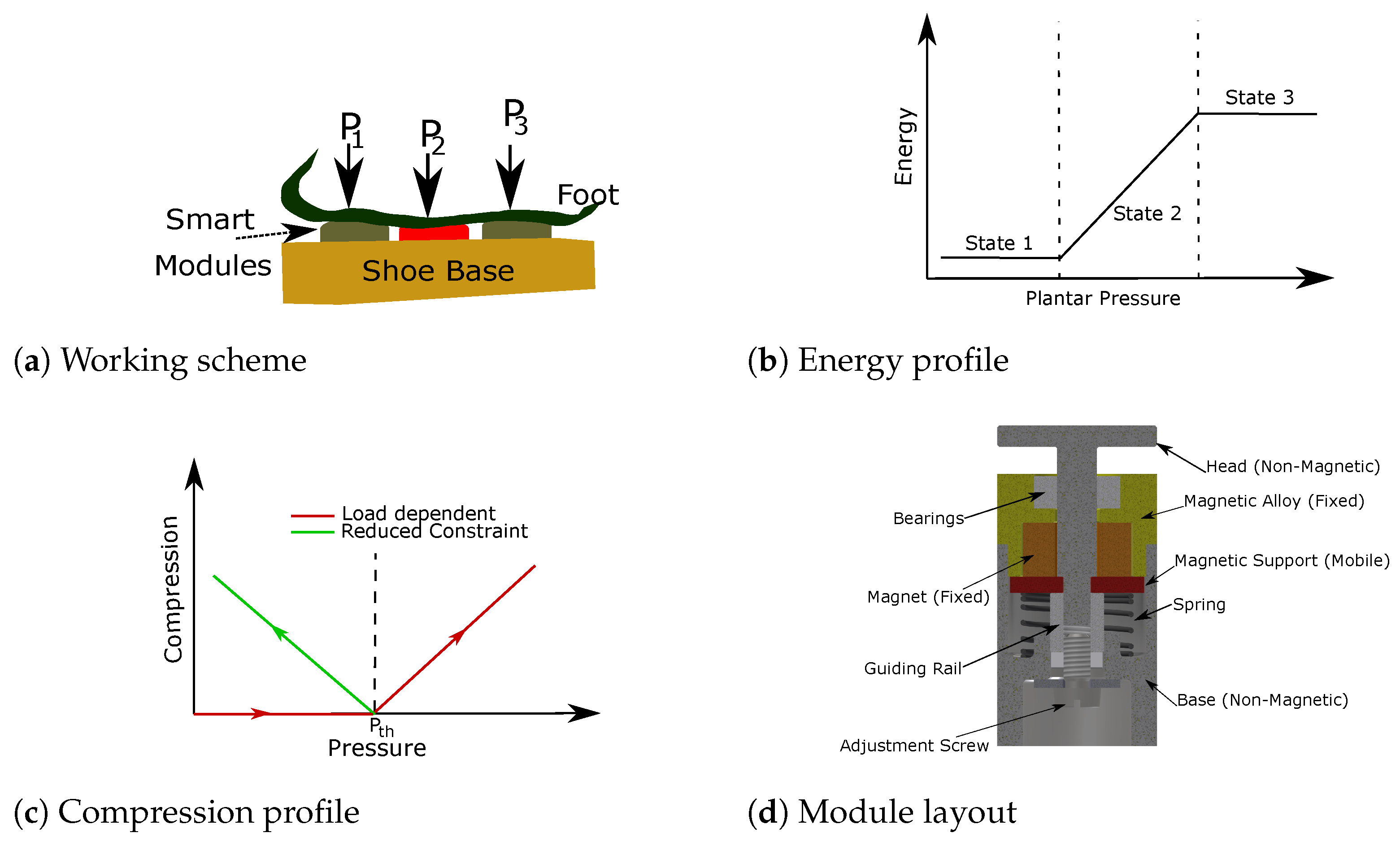
2. System Design and Concept

The module as a device has no access to influence the loading of the user (Figure 1a); therefore, the total PP ( P T ) for a given instance is constant and uncontrollable from the module. On the other hand, the individual PP ( P i , with “i” as the module number) at a given position can be reduced and redistributed to the other spots. Therefore, the redistribution of the PP is achievable by enabling proper functioning of the individual modules. Through the use of passive modules, we aimed to redistribute the PP whenever it reaches a predefined threshold limit ( P t h ).
In Figure 1a, say PP P 2 goes beyond P t h , then the corresponding module should be compressed to distribute the excess pressure among the other modules. This means that the module should be inert for P < P t h and should follow the compression beyond this threshold. The extent of loading pressure is also limited by the limit of the module’s compression P < P L i m i t ; therefore, the redistribution of the PP must be sufficiently performed before the compression limit is reached. In terms of the energy profile, the initial state being inert for P < P t h should be the lowest and only stable state (one stable state of the device). This means that after P > P t h , once the load is reduced, the module should be able to go back to the initial stable state on its own. We can categorize the module energy profile into 3 states (1, 2, and 3) based on the amount of loading (Figure 1b). For the passive module to operate, in addition to the initially stored energy, the other requirement is to have only one stable state (State 1). Multiple stable states means additional stimuli are needed for the switching, which we completely wanted to avoid. State 2 is a compressed state, which would automatically go back to State 1, when the load criteria for State 1 are met ( P < P t h ). When the compression limit of the module is reached, then the module would start acting as a rigid system, therefore leading to a rapid load increment.
The load-dependent movement (Figure 1c) is a typical example of putting a passive spring, which would be compressed depending on the extent of the load imposed. However, there would be an equal amount of reaction force acting on the contact surface (foot) with the compression. Therefore, it would not facilitate the PP’s redistribution. On the other hand, negative stiffness or “reduced constraint” movement allows the reaction force reduction (before the compression limit), and this would redistribute the excess PP among the other modules. The movement followed in the “reduced constraint” phase comprises a reduction of holding or blocking pressure with compression, resulting in a negative slope of the compression–reaction pressure profile. A typical example of a similar scenario could be a buckled beam where the reaction force on the beam becomes reduced following a transition from one stable state to the other. Similarly, an explosion/the sudden release of air/gas from a balloon will result in a similar reaction pressure–compression profile. Therefore, the latter profile is of our interest in the mentioned application. State 2 must be linked to State 1, so that reversibility can be insured. A linear inverse proportionality would lead to the profile shown in Figure 1c, whereas, depending on the nature of the holding force, it could be non-linear as well. To have a lightweight, passive, and low-cost solution, this work considered the use of a permanent magnet where State 1 can be achieved by magnetic strength bonding. The reduced constraint motion of State 2 is feasible to achieve because of the inverse proportionality of the magnetic field strength with the distance. The decision-making in terms of enabling compression is defined by the magnetic holding force, which is decided based on the required threshold value of the PP.
Based on the discussed requirements, a passive module employing a permanent magnet is proposed (Figure 1d). It comprises a non-magnetic head for the loading. Bearings are used for better guiding of the mobile components, whereas a spring is used to facilitate restoring to State 1 when the appropriate loading conditions are met. An adjustment screw is used at the base with which the distance between the magnetic support and the fixed magnet can be controlled. As the magnetic bonding force is inversely dependent on the distance, with this adjustment of the distance, the magnetic holding force can be changed. With the change in the magnetic holding force, the threshold pressure limit of the device can be tuned. This adds the tunability feature to our device. A detailed discussion on the numerical simulation is presented in the next section (Section 3).

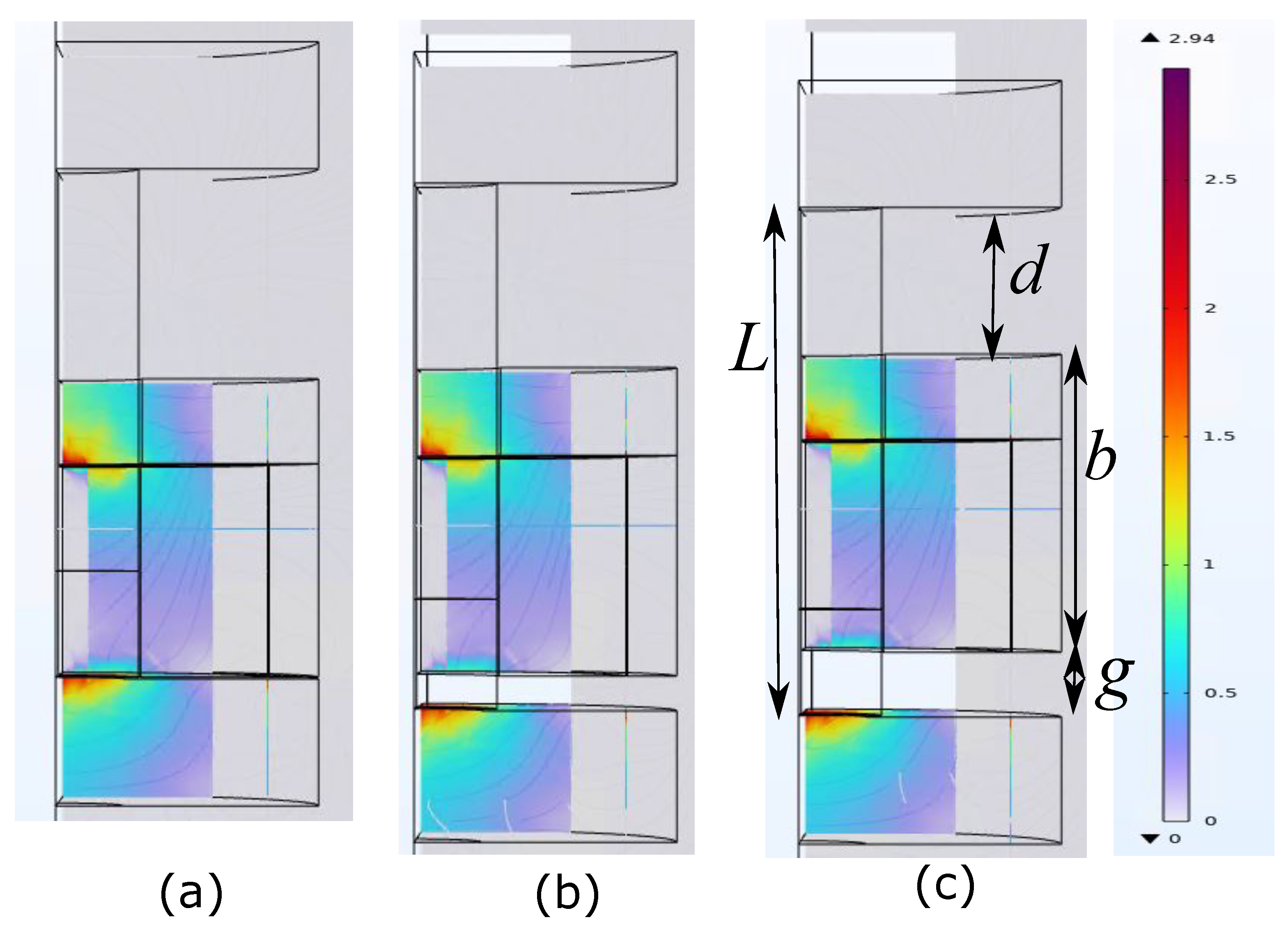
3. Modeling and Simulation

This section presents the numerical modeling and simulation of the proposed device. The COMSOL multiphysics software was used for the numerical modeling. For device to be able to be restored to default State 1, the head should be non-magnetic. Otherwise, it would lead to mainly three problems: first, it may interact with the magnetic environment/loading, leading to a deviation from the targeted behavior. Secondly, it would add up additional magnetic bonding in the direction of the loading (Figure 1d), which would reduce the blocking threshold limit of the device.
The size and magnetic strength of the permanent magnet were chosen based on the bonding strength required (the threshold PP). In this work, we aimed to achieve a bonding strength of up to 800 kPa. A ring magnet with a height of 5 mm, outer diameter of 10 mm, and internal diameter of 4 mm was chosen for this work. This magnet is axially magnetized and gives high axial bonding strength. For the mentioned size, the material properties were chosen based on the availability from the different magnet suppliers and are listed in Table 1.
Therefore, these physics were coupled in the current analysis. The magnetic flux coming (Figure 2) from the ring permanent magnet was modeled as the remnant magnetic flux, while the mechanics involved as the application of the load was modeled using solid mechanics. A complete quasistatic situation was considered in the above analysis. The distance g between the fixed magnet and the mobile magnetic support defines the bonding force between them. For piston length L (the distance between the head and mobile magnetic support; see Figure 2), the free spacing between the head and magnet fixation d, and a fixed magnetic height b, then g can be given by Equation (1).
g = L ( d + b )
For the above simulation, a g of 40 μ m was used (given by Equation (1)), as it better suited the meshing and boundary conditions, while playing with this distance g, an offline tunability in terms of threshold pressure limit can be achieved. From Equation (1), with the increase in d (both L and b are fixed), g decreases; therefore, more d would lead to a stronger magnetic bonding and, so, a high threshold pressure. As, from the practical side, it is easier to measure d than g, we directly refer to d for the tunability. In the COMSOL environment, an input displacement of 1.5 mm was given to the head of the device, and the corresponding impact was measured. From the PP redistribution requirement, 1.5–3 mm of the head/mobile part displacement can be considered sufficient based on the flexibility of human foot skin. Figure 3d presents the corresponding pressure limit obtained from the input displacement of 1.5 mm against different spacings d (1.7–2.7 mm). In Figure 1d, the bottom screw allows the adjustment in spacing, therefore enabling the tunability feature. For a given device, Figure 3b shows that, with the spacing (between the head and fixed end) increment, the threshold pressure limit can be tuned from 69 kPa to 800 kPa. This validates the proof of concept of the pressure tunability.

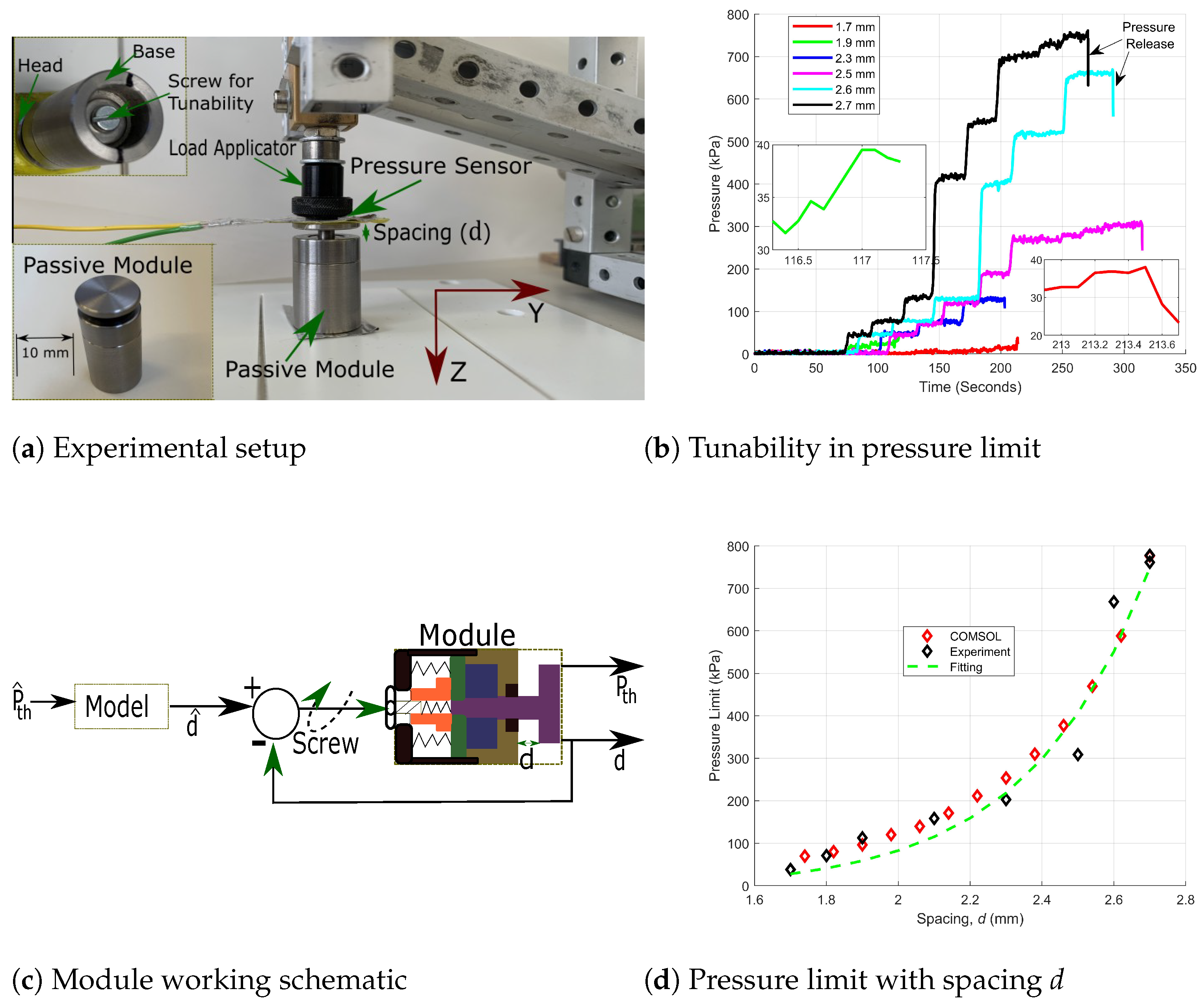
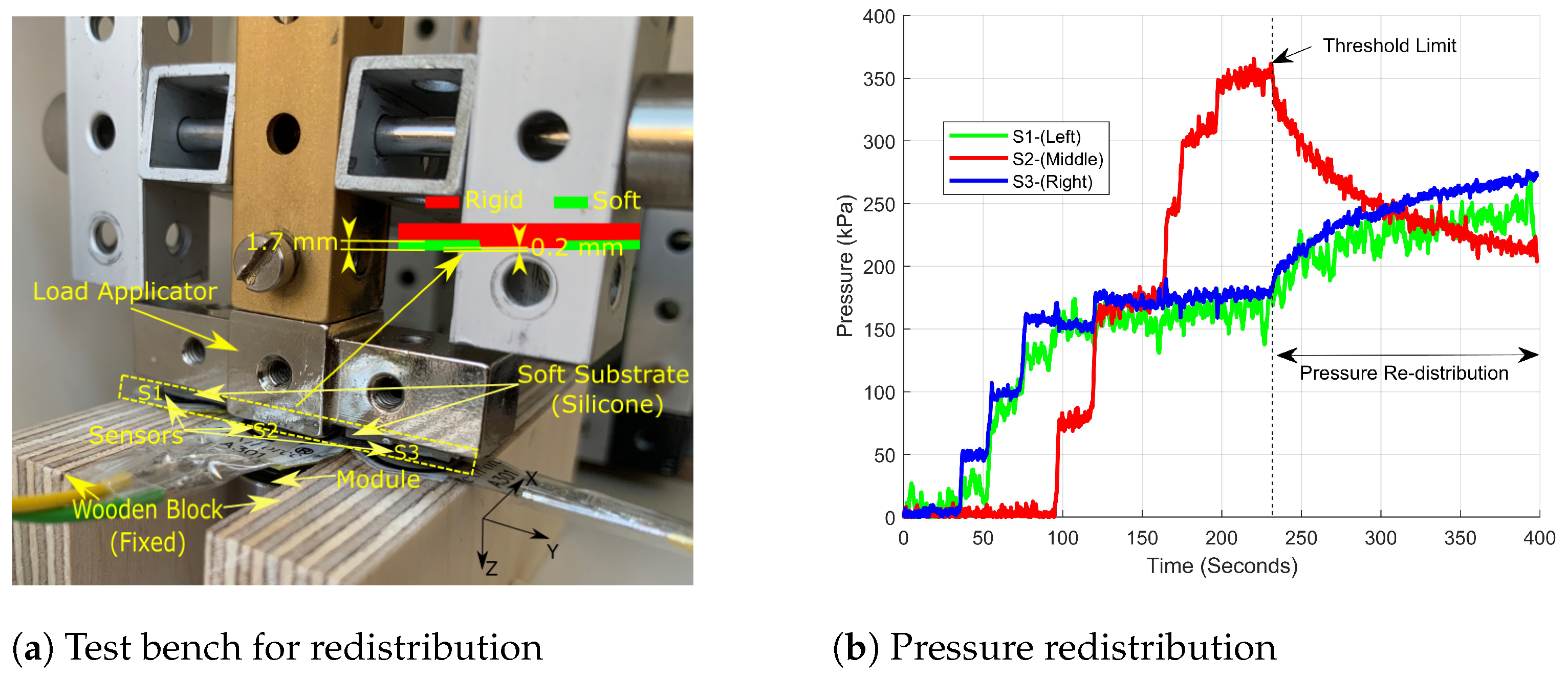
4. Experimental Studies

The non-magnetic part of the device was made of steel (non-magnetic), while the magnetic alloy used in this device was Telar 57 from ARMCO. The permanent magnet used was R-10-04-05-N from supermagnete. The fabricated/assembled device based on the design discussed in the previous sections is shown in Figure 3a. The overall weight of the active device is 16.4 grams.
Figure 3a shows the experimental setup used for the module’s threshold pressure characterization. Thew FlexiForce A301 from Tekscan was used as the pressure sensor, while the USB-6351 from National Instrument was used for signal acquisition. A custom homemade load applicator was used, where weights were manually added for different experiments. The adjustment screw tightened from the base end allowed spacing control between the magnet and movable alloy (Figure 3a).

4.1. Tunability and Calibration

Six different positions between the completely tightened to completely unscrewed states were tested (marked with the respective spacing d in Figure 3b). The threshold pressure limit varied from 38 kPa up to 778 kPa.
Once the threshold limit of pressure was reached, a sudden fall in pressure could be seen, which led to the reduced constraint motion presented in Figure 1c. This negative stiffness profile is significant in enabling the pressure redistribution (discussed in Section 4.2). The minimum spacing d corresponds to the state of the device when the movable alloy is farthest from the magnet; this means the magnetic binding force was lowest. Therefore, it required less pressure to move the head down compared to when the movable alloy was closest to the magnet (a higher d). In order to set the proposed module for a desired threshold pressure limit, it becomes important to map the observable parameter, d, which is the spacing between the head and the fixation of the module (Figure 3c). The controllable access that the user would have is the screwing, and so, a desired spacing d ^ can be obtained based on the extent of the screwing. As the threshold pressure and actual spacing d (directly dependent on spacing g from Equation (1)) are non-linearly related, an exponential relation was considered and is given by Equation (2). The desired threshold pressure P ^ t h can be achieved by finding the corresponding spacing d ^ (using a mapped calibration), which can be visually tuned (to make d ^ = d) by the user based on the screwing.
d ^ = a 1 × log ( a 2 × P ^ t h + a 3 )
For the proposed device, a spacing d of 1.7–2.7 mm is achievable, corresponding to the completely screwed and unscrewed configuration, respectively. Different experiments were performed with different spacings, and the corresponding threshold pressure limits were recorded. Figure 3d presents the experimentally obtained results and the fitting based on Equation (2) using the identified parameters a i as listed in Table 2. A deviation in the lowest limit between COMSOL and the experiment possibly came from the non-linearity in the flux leakage and/or the lack of the precise inclusion of the geometrical/material-based properties.

4.2. Pressure Redistribution

The pressure-sustaining capability up to 778 kPa of the proposed device was validated along with its tunability to change this limit to as low as 38 kPa. In order to use this module for PP redistribution among diabetic patients, there would be a need for an array of such modules distributed in the shoes. To be able to validate the proof of the device’s functionality, a simplified version of foot loading (as shown in Figure 1a) was approximated experimentally. The experimental setup is shown in Figure 4a, where the foot was replaced by a soft–rigid combined surface linked to a custom-made load applicator, while the shoe base by fixed rigid surfaces. The proposed module was placed between two wooden blocks, which were fixed. The FlexiForce A301 sensor from Tekscan was fixed, respectively, on the head of the module and on the surface of the wooden blocks (in line along the Y axis) and marked S1, S2, and S3 (respectively, from left to right). The module was set to a threshold limit of 350 kPa by adjusting the spacing d to about 2.45 mm. The load applicator was positioned on the head of the module; the load applicator end comprised soft and rigid materials, as shown in Figure 4a. With a completely rigid interface in the middle and softer on the sides, a higher load distribution profile at the center can be created (similar to Figure 1a). The soft silicone Elastosil R 101 from Wacker was used as a soft interface; a thickness of 1.7 mm was used (0.2 mm stepped out from the rigid part), as it was convenient for the compression range for the different spacings used and the desired pressure at the loading end.
A manually added load was applied and increased using a custom-made load applicator; the obtained pressure measured by the three sensors S1, S2, and S3 over time is shown in Figure 1b. During the initial phase of the loading, the soft surfaces on the sides (Figure 1a) deformed, and so, until they reached the same Z-level (as for the rigid part), the applied load was distributed among these two soft ends (left and right of the rigid part). Once this limit was reached for these soft ends (~95 s), further loading would start appearing on the centrally placed module. This continued to cause the placed module to be under higher pressure compared to the surfaces on the left and right. Once the threshold pressure limit was reached on the module end (~231 s), the excess pressure was redistributed. The module was configured to withstand a pressure of up to 350 kPa; therefore, once this value was reached, an additional 40 kPa was applied to allow the excess pressure’s redistribution. The opening of the module happened around 360 kPa, while the total pressure (combined from S1, S2, and S3) before opening was ~720 kPa. Following the pressure redistribution, the total final pressure obtained was ~740 kPa. The noise level of the sensors signal acquired was ~20 kPa; therefore, overall, the total pressure measured before opening and after redistribution was the almost same, which is consistent with what it was supposed to be under the static loading condition. The proposed device, therefore, allows pressure distribution among the neighboring exposed area once the defined threshold limit is reached. Another interesting side of the pressure redistribution noticed in Figure 1b for S2 consisted of the achieved pressure after offloading, which was about 210 kPa, which means more than a 35% reduction following offloading. International guidelines recommend [37] achieving at least a 30% reduction in peak plantar pressure to reduce the risk of foot ulcers among diabetic people. Therefore, the obtained result also validated the device’s capability to address the need in the prescribed limit. This redistribution was tested only with three modules (S1, S2, and S3), which is expected to be improved further (more sites for excess distribution) with the use of a higher number of modules, as was the case in our active offloading footwear featured in [29].
In terms of the intended use of the proposed device, it is important to mention that, being a passive device, it brings many advantages, but also has some limitations. The key limitations would be the real-time feedback to the user; however, this limitation may be addressed by defining the intended way to use the proposed offloading device. Once the array of the proposed module is implemented (as in [29]), there would be a need for the identification of the appropriate peak pressure for the given user depending on his/her foot condition. A healthcare expert may recommend this peak pressure, which may differ locally throughout the foot. Based on the recommendation, the peak pressure can be pre-set for each of the modules, and the user may follow up time to time with medical consultations based on his/her personal needs or upon the recommendation of the diabetic expert. The need for appropriate peak pressure information and its mapping on the foot would also be needed for an active offloading device. Therefore, the inclusion of a diabetic healthcare expert would always be recommended in diabetic foot care.

5. Conclusions

Offloading is one of the highly rated and trusted methods for the prevention and care of FU among persons with diabetes. This work presented an alternative offloading device, which was inspired by our previously reported work on active offloading. The idea is to provide a passive alternative for excess pressure distribution along with keeping the feature of peak pressure tunability. The proposed module exhibits offline tunability by the simple adjustment of a screw, leading to the pressure limit variation from 38 kPa to 778 kPa (more than 20-times tunability). This device is free from external feeding, in terms of energy, electronics, and active control. This makes it highly compatible for daily and normal life use. For a relatively lower threshold limit (say 400 kPa), low-cost additive manufacturing can be used, making the cost of a single module less than USD 10. A single device’s head diameter is 13 mm, which allows a more-local monitoring and load distribution. As future work, we will aim to develop an array of the proposed module embedded inside complete shoes (as reported in our active offloading work). With the help of a diabetic expert, the special peak pressure needs should be studied, and then, accordingly, the peak thresholds can be configured for the array. Therefore, the future work will also aim for in-depth clinical studies and the validation of the offloading using the module array.

Author Contributions

Conceptualization, B.T. and K.J.; methodology, B.T. and Y.C.; software, B.T.; validation, B.T., K.J., P.G. and Y.C.; formal analysis, B.T., K.J, P.G., C.K., S.L.N. and Y.C.; investigation, B.T., K.J, P.G, C.K., S.L.N. and Y.C.; resources, B.T.; data curation, B.T.; writing—original draft preparation, B.T.; writing—review and editing, all authors; visualization, all authors; supervision, Z.P., Y.C. and Y.P.; project administration, Z.P. and Y.P.; funding acquisition, Z.P. and Y.P. All authors have read and agreed to the published version of the manuscript.

Funding

This research was funded by the Swiss National Science Foundation (SNSF) and the Innosuisse-Swiss Innovation Agency through BRIDGE funding Program under Grant 20B2-1-181020.

Data Availability Statement

The data presented in this study are available on request from the corresponding author. The data are not publicly available due to confidentiality of the project.

Conflicts of Interest

The authors declare no conflicts of interest.

References

  1. GBD 2021 Diabetes Collaborators. Global, regional, and national burden of diabetes from 1990 to 2021, with projections of prevalence to 2050: A systematic analysis for the Global Burden of Disease Study 2021. Lancet 2023, 402, 203–234. [Google Scholar] [CrossRef] [PubMed]
  2. Mekkes, J.R.; Loots, M.A.M.; Wal, A.C.V.D.; Bos, J.D. Causes, investigation and treatment of leg ulceration. Br. J. Dermatol. 2003, 148, 388–401. [Google Scholar] [CrossRef]
  3. Jouven, X.; Lemaître, R.N.; Rea, T.D.; Sotoodehnia, N.; Empana, J.P.; Siscovick, D.S. Diabetes, glucose level, and risk of sudden cardiac death. Eur. Heart J. 2005, 26, 2142–2147. [Google Scholar] [PubMed]
  4. Hou, Y.; Zhou, M.; Xie, J.; Chao, P.; Feng, Q.; Wu, J. High glucose levels promote the proliferation of breast cancer cells through GTPases. Breast Cancer 2017, 9, 429–436. [Google Scholar] [CrossRef] [PubMed]
  5. Armstrong, D.G.; Lipsky, B.A. Diabetic foot infections: Stepwise medical and surgical management. Int. Wound J. 2004, 1, 123–132. [Google Scholar] [CrossRef] [PubMed]
  6. Chamberlain, R.C.; Fleetwood, K.; Wild, S.H.; Colhoun, H.M.; Lindsay, R.S.; Petrie, J.R.; McCrimmon, R.J.; Gibb, F.; Philip, S.; Sattar, N.; et al. Foot Ulcer and Risk of Lower Limb amputation or Death in People With Diabetes: A National Population-Based Retrospective Cohort Study. Diabetes Care 2022, 45, 83–91. [Google Scholar] [CrossRef]
  7. Chen, L.; Sun, S.; Ran, X. Global mortality of diabetic foot ulcer: A systematic review and meta-analysis of observational studies. Diabetes Obes. Metab. 2023, 25, 36–45. [Google Scholar]
  8. Wu, H.; Ni, R.; Shi, Y.; Hu, Y.; Shen, Z.; Pang, Q.; Zhu, Y. The Promising Hydrogel Candidates for Preclinically Treating Diabetic Foot Ulcer: A Systematic Review and Meta-Analysis. Adv. Wound Care 2023, 12, 28–37. [Google Scholar] [CrossRef]
  9. Abid, H.M.U.; Hanif, M.; Mahmood, K.; Aziz, M.; Abbas, G.; Latif, H. Wound-Healing and Antibacterial Activity of the Quercetin-4-Formyl Phenyl Boronic Acid Complex against Bacterial Pathogens of Diabetic Foot Ulcer. ACS Omega 2022, 7, 24415–24422. [Google Scholar] [CrossRef]
  10. Becerra-Bayona, S.M.; Solarte-David, V.A.; Sossa, C.L.; Mateus, L.C.; Villamil, M.; Pereira, J.; Arango-Rodríguez, M.L. Mesenchymal stem cells derivatives as a novel and potential therapeutic approach to treat diabetic foot ulcers. Endocrinol. Diabetes Metab. Case Rep. 2020, 2020. [Google Scholar] [CrossRef]
  11. Yuan, Y.; Ding, X.; Jing, Z.; Lu, H.; Yang, K.; Wang, Y.; Xu, H. Modified tibial transverse transport technique for the treatment of ischemic diabetic foot ulcer in patients with type 2 diabetes. J. Orthop. Transl. 2021, 29, 100–105. [Google Scholar] [CrossRef] [PubMed]
  12. Wang, M.; Yang, Y.; Yuan, K.; Yang, S.; Tang, T. Dual-functional hybrid quaternized chitosan/Mg/alginate dressing with antibacterial and angiogenic potential for diabetic wound healing. J. Orthop. Transl. 2021, 30, 6–15. [Google Scholar] [CrossRef] [PubMed]
  13. Lazo-Porras, M.; Bernabe-Ortiz, A.; Taype-Rondan, A.; Gilman, R.H.; Malaga, G.; Manrique, H.; Neyra, L.; Calderon, J.; Pinto, M.; Armstrong, D.G.; et al. Foot thermometry with mHeath-based supplementation to prevent diabetic foot ulcers: A randomized controlled trial. Wellcome Open Res. 2020, 5, 23. [Google Scholar] [CrossRef]
  14. Chatwin, K.E.; Abbott, C.A.; Boulton, A.J.M.; Bowling, F.L.; Reeves, N.D. The role of foot pressure measurement in the prediction of diabetic foot ulceration-A comprehensive review. Diabetes/Metabolism Res. Rev. 2020, 36, e3258. [Google Scholar]
  15. Robinson, C.C.; Balbinot, L.F.; Silva, M.F.; Achaval, M.; Zaro, M.A. Plantar Pressure Distribution Patterns of Individuals with Prediabetes in Comparison with Healthy Individuals and Individuals with Diabetes. J. Diabetes Sci. Technol. 2013, 7, 1113–1121. [Google Scholar]
  16. Bharara, M.; Najafi, B.; Armstrong, D.G. Methodology for Use of a Neuroprosthetic to Reduce Plantar Pressure: Applications in Patients with Diabetic Foot Disease. J. Diabetes Sci. Technol. 2012, 6, 222–224. [Google Scholar]
  17. Heck, I.; Lu, W.; Wang, Z.; Zhang, X.; Adak, T.; Cu, T.; Crumley, C.; Zhang, Y.; Wang, X.S. Soft, Wireless Pressure-Sensor-Integrated Smart Bandage for the Management of Diabetic Foot Ulcers. Adv. Mater. Technol. 2022, 8, 2200821. [Google Scholar] [CrossRef]
  18. Mahmud, S.; Khandakar, A.; Chowdhury, M.E.H.; Moniem, M.A.; Reaz, M.B.I.; Mahbub, Z.B.; Sadasivuni, K.K.; Murugappan, M.; Alhatou, M. Fiber Bragg Gratings based smart insole to measure plantar pressure and temperature. Sens. Actuators A Phys. 2023, 350, 114092. [Google Scholar]
  19. Nga, D.T.N.; Mattana, G.; Thu, V.T.; Roussel, R.; Piro, B. A simple flexible printed capacitive pressure sensor for chronic wound monitoring. Sens. Actuators A Phys. 2022, 338, 113490. [Google Scholar]
  20. Ferber, R.; Webber, T.; Kin, B.; Everett, B.; Groenland, M. Validation of Plantar Pressure Measurements for a Novel In-Shoe Plantar Sensory Replacement Unit. J. Diabetes Sci. Technol. 2013, 7, 1167–1175. [Google Scholar] [CrossRef]
  21. Park, C.; Mishra, R.; Vigana, D.; Macagno, M.; Rossotti, S.; D’Huyvetter, K.; Armstrong, J.G.D.G.; Najafi, B. Smart Offloading Boot System for Remote Patient Monitoring: Toward Adherence Reinforcement and Proper Physical Activity Prescription for Diabetic Foot Ulcer Patientst. J. Diabetes Sci. Technol. 2022, 17, 42–51. [Google Scholar] [PubMed]
  22. Tiwari, B.; Ntella, S.L.; Jeanmonod, K.; Germano, P.; Koechli, C.; Pataky, Z.; Perriard, Y.C.Y. A Polyester-Nylon Blend Plantar Pressure Sensing Insole for Person with Diabetes. IEEE Sens. Lett. 2024, 8, 1–4. [Google Scholar] [CrossRef]
  23. Lazzarini, P.A.; Jarl, G.; Gooday, C.; Viswanathan, V.; Caravaggi, C.F.; Armstrong, D.G.; Bus, S.A. Effectiveness of offloading interventions to heal foot ulcers in persons with diabetes: A systematic review. Diabetes Metab. Res. Rev. 2020, 36, e3275. [Google Scholar] [CrossRef] [PubMed]
  24. Lazzarini, P.A.; Jarl, G. Knee-High Devices Are Gold in Closing the Foot Ulcer Gap: A Review of Offloading Treatments to Heal Diabetic Foot Ulcers. Medicina 2021, 57, 941. [Google Scholar] [CrossRef] [PubMed]
  25. Low, J.H.; Khin, P.M.; Yeow, C.H. A Pressure-Redistributing Insole using Soft Sensors and Actuators. In Proceedings of the 2015 IEEE International Conference on Robotics and Automation (ICRA), Seattle, WA, USA, 26–30 May 2015. [Google Scholar]
  26. Mo, Y.; Qaiser, Z.; Ou, H.; Johnson, S. A Reconfigurable and Adjustable Compliance System for the Measurement of Interface Orthotic Properties. IEEE Trans. Neural Syst. Rehabil. Eng. 2021, 29, 1886–1894. [Google Scholar] [PubMed]
  27. Perriard, Y.; Pataky, Z.; Grivon, D.; Civet, Y.R.C. System for Adjusting Pressure Locally on the Skin and Subcutaneous Tissue. U.S. Patent 2017/0348181 A1, 16 March 2021. [Google Scholar]
  28. Zur, L. Programmable Pressure Management Support Surface. U.S. Patent 10,463,526 B1, 1 October 2021. [Google Scholar]
  29. Hemler, S.; Ntella, S.L.; Jeanmonod, K.; Köchli, C.; Tiwari, B.; Civet, Y.; Perriard, Y.; Pataky, Z. Intelligent plantar pressure offloading for the prevention of diabetic foot ulcers and amputations. Front. Endocrinol. 2023, 14, 1166513. [Google Scholar]
  30. Zhang, X.; Wang, H.; Du, C.; Fan, X.; Cui, L.; Chen, H.; Deng, F.; Tong, Q.; He, M.; Yang, M.; et al. Custom-Molded Offloading Footwear Effectively Prevents Recuurence and Amputation, and Lowers Mortality Rates in High-Risk Diabetic Foot Patients: A Multicenter, Prospective Observational Study. Diabetic Metab. Syndr. Obes. Targets Ther. 2022, 15, 103–109. [Google Scholar]
  31. Roser, M.C.; Canavan, P.K.; Najafi, B.; Watchman, M.C.; Vaishnav, K.; Armstrong, D.G. Novel In-Shoe Exoskeleton for Offloading of Forefoot Pressure for Individuals With Diabetic Foot Pathology. J. Diabetes Sci. Technol. 2017, 11, 874–882. [Google Scholar]
  32. Shaulian, H.; Gefen, A.; Biton, H.; Wolf, A. Graded stiffness offloading insoles better redistribute heel plantar pressure to protect the diabetic neuropathic foot. Gait Posture 2023, 101, 28–34. [Google Scholar] [CrossRef]
  33. Chatzistergos, P.E.; Gatt, A.; Formosa, C.; Farrugia, K.; Chockalingam, N. Optimised cushioning in diabetic footwear can significantly enhance their capacity to reduce plantar pressure. Gait Posture 2020, 79, 244–250. [Google Scholar] [CrossRef]
  34. Maharana, P.; Sonawane, J.; Belehalli, P.; Ananthasuresh, G.K. Self-offloading therapeutic footwear using compliant snap-through arches. Wearable Technol. 2022, 3, e7. [Google Scholar]
  35. Chatzistergos, P.E.; Chockalingam, N. A novel concept for low-cost non-electronic detection of overloading in the foot during activities of daily living. R. Soc. Open Sci. 2020, 8, 202035. [Google Scholar] [CrossRef]
  36. Wang, L.; Jones, D.; Chapman, G.J.; Siddle, H.J.; Russell, D.A.; Alazmani, A.; Culmer, P. A Review of Wearable Sensor Systems to Monitor Plantar Loading in the Assessment of Diabetic Foot Ulcers. IEEE Trans. Biomed. Eng. 2020, 67, 1989–2004. [Google Scholar] [CrossRef]
  37. Fernando, M.E.; Crowther, R.G.; Lazzarini, P.A.; Sangla, K.S.; Wearing, S.; Buttner, P.; Golledge, J. Plantar pressures are higher in cases with diabetic foot ulcers compared to controls despite a longer stance phase duration. BMC Endocr. Disord. 2016, 16, 51. [Google Scholar] [CrossRef]
Figure 1. Working schematic, energy, compression profile, and device layout.
Asi 07 00009 g001
Figure 2. Simulated device with magnetic field strength (T). (a) Initial configuration: State 1 (b); partial opening: State 2; (c) complete opening: State 3.
Asi 07 00009 g002
Figure 3. Experimental setup, tunable profile, working scheme, tunability with spacing.
Asi 07 00009 g003
Figure 4. Experimental setup and pressure redistribution validation.
Asi 07 00009 g004
Table 1. Properties of the chosen magnet.
ParameterValue
Recoil Permeability1.05
Effective Remanent Flux Density (Norm)2.15
Young Modulus (GPa)350
Poisson’s Ratio0.35
Table 2. Identified parameters for the calibration of the module.
i (for a i )Value
10.33
24.35
343.48
Disclaimer/Publisher’s Note: The statements, opinions and data contained in all publications are solely those of the individual author(s) and contributor(s) and not of MDPI and/or the editor(s). MDPI and/or the editor(s) disclaim responsibility for any injury to people or property resulting from any ideas, methods, instructions or products referred to in the content.

