Article

Theoretical Analysis of a Biomass-Driven Single-Effect Absorption Heat Pump for Heating and Cooling Purposes

by
Evangelos Bellos
1,2,*,
Panagiotis Lykas
2 and
Christos Tzivanidis
2
1
Department of Mechanical Engineering Educators, School of Pedagogical and Technological Education (ASPETE), GR 151 22 Amarousion, Greece
2
Thermal Department, School of Mechanical Engineering, National Technical University of Athens, Zografou, Heroon Polytechniou 9, GR 157 80 Athens, Greece
*
Author to whom correspondence should be addressed.
Appl. Syst. Innov. 2022, 5(5), 99; https://doi.org/10.3390/asi5050099
Submission received: 12 September 2022 / Revised: 2 October 2022 / Accepted: 5 October 2022 / Published: 9 October 2022

Abstract

:
Renewable energy exploitation in the building sector can lead to significant energy savings and carbon dioxide emission avoidance. The objective of this study is the detailed investigation of a biomass-driven absorption heat pump for heating and cooling. The heat pump is practically a single-effect absorption chiller operating with the Lithium-bromide/water solution and it has been properly modified for heating production during the winter. This system is a novel one and its combination with a biomass boiler was examined for the first time, especially for covering both heating and cooling needs. For the present study, a typical building in Athens, Greece, with a 400 m2 floor area is selected to be coupled with the suggested heating/cooling configuration. The analysis was conducted by using TRNSYS software for the estimation of the building’s thermal loads and with the Engineering Equation Solver for determining the heat pump behavior. According to the results, the yearly biomass consumption is found to be 3.76 tons covering a heating demand of 9136 kWh and cooling demand of 8168 kWh. The seasonal energy cooling performance was found to be 0.751, while the seasonal energy heating performance was at 1.307. Moreover, the proposed configuration was found to have economic and environmental benefits compared to conventional units with an oil boiler and heat pump for cooling. Specifically, the present system leads to 10.8% lower operational costs and 4.8% lower primary energy demand, while there are significant amounts of CO2 avoidance.

1. Introduction

Renewable energy utilization is a vital weapon to face the challenges of high electricity prices, global warming, and the increasing energy needs of humanity [1]. The building sector is responsible for about 40% of the worldwide energy demand [2] and thus the utilization of renewables in buildings is a proper way to reach sustainability [3]. Solar irradiation, biomass, wind energy, and geothermal energy are the most representative renewable energy sources that can be exploited in the building sector in various ways. Among them, the use of biomass gives some important advantages [4,5] which make it a very competitive renewable energy source [6]. More specifically, biomass can produce thermal energy of high temperatures with the proper boiler design, and it can be used when there is a demand, something that solves the storage issue that other renewable energies face (e.g., photovoltaics and wind turbines).
In the literature, there are plenty of studies on the utilization of renewable energies in the building sector. Soltero et al. [7] suggested that the use of biomass for district heating purposes is a sustainable choice and they conducted a detailed sustainability analysis for different cities in Spain. Chen et al. [8] found that the incorporation of heat pumps in a district heating system with biomass can enhance the overall performance by about 17%. Zhang et al. [9] investigated a hybrid solar/biomass heating system and they found solar coverage at 63.3% and system exergy efficiency at 16.2%. Nami et al. [10] studied a solar/biomass-fed trigeneration system for heating, cooling, and power production. Thermal photovoltaics, a biomass boiler, power blocks for electricity, heat exchangers for heating, and an absorption chiller for cooling production, are incorporated into the cycle. The system exergy efficiency was found close to 34%. Bellos et al. [11] examined a solar/biomass multigeneration unit for electricity, cooling, and heating production at two temperature levels. They coupled an organic Rankine cycle with a compression heat pump and they found the system exergy efficiency to be 21.8%. Tsimpoukis et al. [12] studied a solar/biomass polygeneration system based on the use of a supercritical CO2 cycle. They found that the total energy efficiency of the system reaches up to 164%, something that is justified by the partial operation of the system as a heat pump. Bellos and Tzivanidis [13] studied a biomass-based polygeneration system based on a novel CO2 supercritical cycle. They calculated the system’s energy efficiency at 78.1% and the respective exergy efficiency at 26.3%. Xing and Li [14] studied a biomass/geothermal polygeneration unit for power, heating, cooling, and hydrogen production. The energetic efficiency was found to be 79.5%, while the respective exergetic was at 17.9%. Rezaei et al. [15] studied a biomass/geothermal heating configuration from a financial point of view. They highlighted the need for a detailed economic analysis, as well as the need for using a storage device for storing heat when both heat sources provide heat in the system.
Moreover, it is important to highlight the advantage of thermal renewable energies (e.g., biomass, solar energy, geothermal energy) due to the ability for thermal storage which leads to grid flexibility solution. Advanced techniques have been developed aiming to store thermal energy in a compact and efficient way. The use of phase change materials (PCM) is an important technology that can lead to a significant performance in the case combination with other devices. There are examples that combine PCM with storage tanks [16], finned storage packed tubes [17], heat exchangers [18], batteries [19], etc. Additionally, the PCM can be used in applications for cooling storage [20] which is an important option for the sustainability of future buildings.
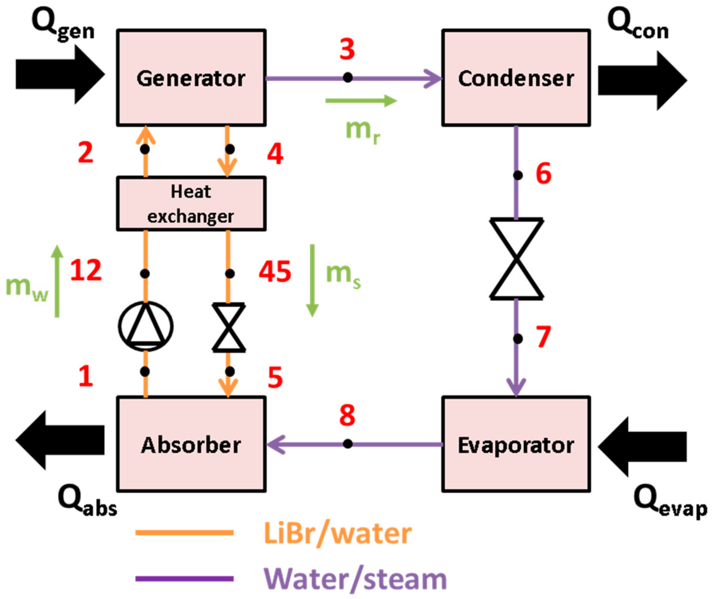
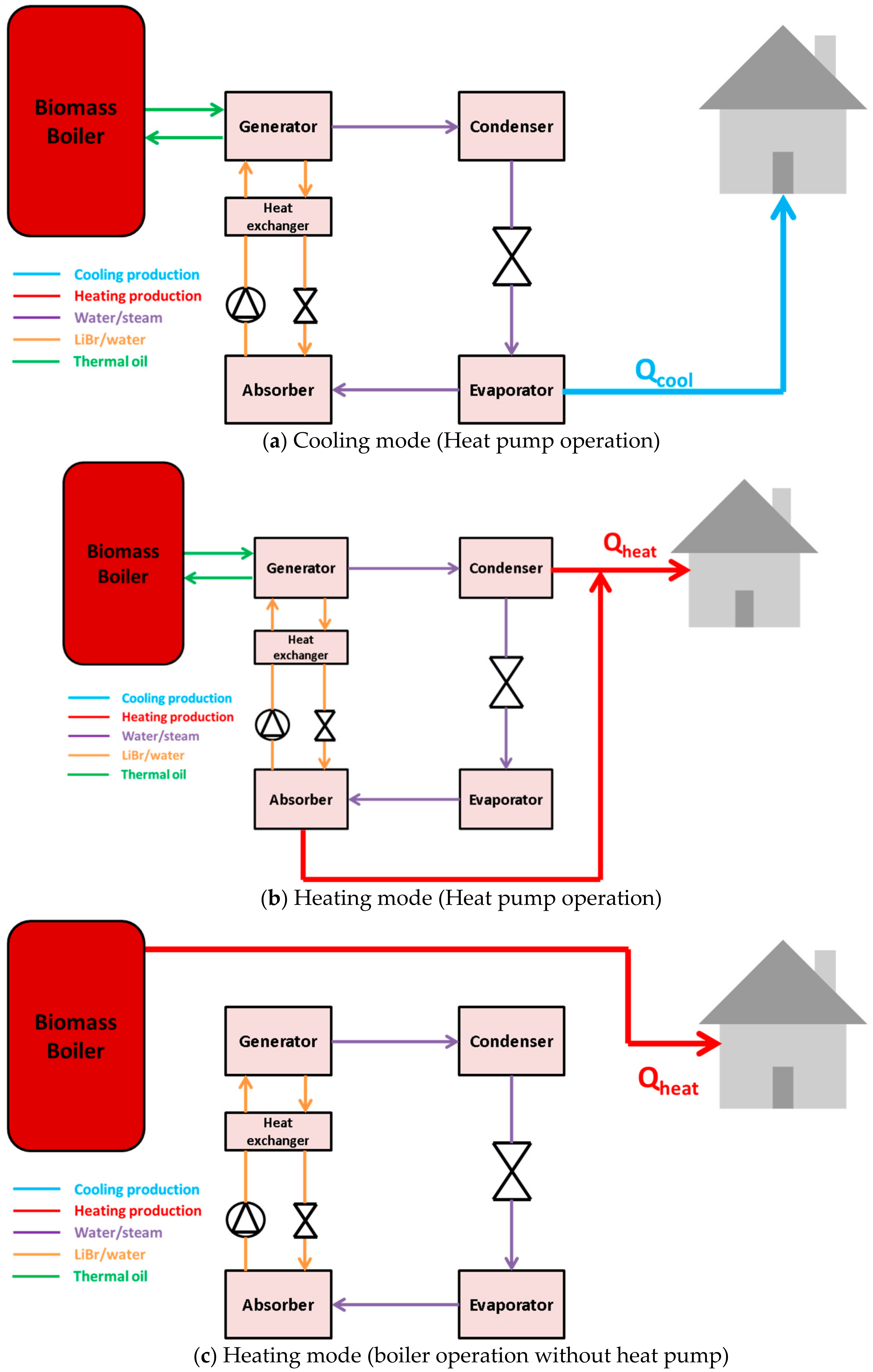
The present study investigates a configuration for both heating and cooling in buildings, based on a biomass-powered absorption heat pump operated with LiBr/H2O working substance. Biomass pellets are burned in a boiler to input driving heat to the absorption machine at a temperature of 110 °C. In the summer period, the heat pump evaporator can ensure a cooling temperature of around 5 °C. In cold weather, space heating is supplied at a temperature of 50 °C from the absorber and the condenser, while on very cold days the boiler heats directly the building. Thus, heating and cooling demands during a whole year can be covered by a dual-purposed biomass-driven heat pump, occasionally backed by the biomass boiler, which constitutes a novelty. The energy, economic and environmental benefits of the suggested design were investigated. A residential building with a floor area of 400 m2 in Athens, Greece, was selected as a potential implementation site. The building thermal loads were analyzed by a purposely developed TRNSYS model [21]. The thermodynamic model of the absorption heat pump employed the Engineering Equation Solver [22].

2. Material and Methods

2.1. The Examined Heating/Cooling System

The first step in this study is the presentation of the single-effect absorption heat pump which is given in Figure 1. This device operates with LiBr/water working pair and it is a single-stage machine. The heat input of high temperature (e.g., 110 °C) is given in the generator from the boiler and also heat input of low temperature is given from the evaporator. The other devices (condenser and absorber) reject heat from the system to the ambient or the building depending on the operating mode. During the summer, the evaporator absorbs energy from the building and put it in the device, while during the winter the evaporator absorbs heat from the ambient.
More specifically, the heat input in the generator makes possible the high-pressure steam evaporation (state point 3) which feeds the condenser where heat is rejected and the outlet (state point 6) is a high-pressure saturated liquid. This quantity is expanded in the throttling valve without losing energy and it becomes a low-pressure liquid/vapor mixture (state point 7) that feeds the evaporator. Inside the evaporator device, saturated steam of low pressure is created (state point 8) with heat absorbance. This quantity goes into the absorber where there is a LiBr/water weak solution of low pressure. In this device, the steam is absorbed by the LiBr crystals, and heat is rejected. The weak solution (state point 1) leaves the absorber, then with a solution pump reaches high pressure (state point 12) and goes to the solution heat exchanger where it is warmed up (state point 2) before the inlet to the generator. On the other side of the circuit, the strong solution leaves the generator (state point 4), then goes to the heat exchanger where it rejects heat to the weak solution and finally it reaches a colder high-pressure strong solution (state point 45). This quantity is expanded without losing energy in a throttling valve (state point 5) and goes into the absorber in order to close the total cyclic process.
Figure 2 depicts the suggested unit for heating and cooling with the utilization of biomass. There are three modes of the system, as shown in Figure 2. More specifically, Figure 2a shows the cooling mode where the evaporator of the heat pump feeds by cooling the building, while the biomass boiler feeds the generator with heat input. Thermal oil is used as the heat transfer fluid from the boiler to the generator due to the high-temperature levels. Specifically, the generator temperature is selected at 110 °C in order to be able the operation during the summer period, while heat rejection temperatures in the condenser and the absorber were set at 10 K over the ambient temperature. In this scenario, the evaporator temperature is set at 5 °C in order to be able to feed a cooling system with fan coils.
In the heating mode, there are two cases depending on the ambient temperature. More specifically, the heat pump absorbs heat from the ambient during the winter in order to transfer it, after the upgrade, in the building. However, the water in the cycle cannot go lower than 4 °C, due to freezing reasons. Thus, in low ambient temperatures, the absorption heat pump does not operate and then, the biomass boiler feeds directly the fan coils of the building. Assuming a pinch point temperature of 5 K [23], the critical ambient temperature that separates the heating operating modes is equal to Tam,cr = 9 °C. More specifically, when the Tam ≥ 9 °C, then the heat pump operates and provides heating in the building from the condenser and the absorber. On the other hand, when Tam < 9 °C, the heat pump is not possible to operate and the boiler gives direct heat input in the building.
Figure 2b depicts the heating scenario where the condenser and the absorber reject heat to the building to cover its thermal needs, while the evaporator absorbs heat from the ambient. The generator operates at 110 °C in order to give the proper heat input to the system. Thermal oil is used as the heat transfer fluid for transferring thermal energy from the boiler to the generator.
Figure 2c shows the system with the operation of the boiler without the use of the heat pump. The boiler gives input directly to the fan coils of the building because the heat pump cannot operate when the ambient temperature is lower than 9 °C. In this scenario, the performance of the system is reduced and thus the climate conditions of the examined region play a significant role in the energy behavior of the system in the heating mode. In other words, in cold climates, the present system is not so effective because (i) the ambient temperature is lower than 9 °C for a great percentage of the year, and (ii) the cooling loads are restricted during the summer. However, this system is an interesting choice for climate conditions such as in the examined study case in Athens, Greece.
In the present work, the boiler has been selected to have a nominal efficiency of 90% [11]. The higher heating value (HHV) of the biomass is 18467 kJ/kg which corresponds to typical pellets [24]. The dry composition of the selected biomass is 49.7% C, 6.0% H, 41.0% O, 1.7% N, 0.0% S, 0.1% Cl, 1.5% Ash [24], while the as received has 15% moisture [11]. Table 1 includes the main information regards the system analysis.

2.2. The Examined Building

A building with dimensions (20 m × 20 m × 3 m) is examined in the present work. This building is located in Athens, Greece, and it has a floor area of 400 m2 and a volume of 1200 m3. It has four external walls oriented in four directions (south, west, north and east), while the south wall includes a window of 10 m2 area. The ground slab comes in touch with the ground while the roof is in touch with the ambient air. Additionally, all the external walls are in touch with the external air and there are no shadings from other buildings or obstacles. Table 2 includes the materials of the structural components, as well as the respective material thermal properties. More details regarding the system simulation are included in Table 3. The set point temperature levels were selected at 20 °C in the winter period and 26 °C in the summer period, as typically selected in the residential buildings. The infiltration and natural ventilation rates were selected at 1 air change per hour, while the internal gain of the building for appliances and lighting was set at 7 W/m2. The aforementioned parameters were selected to have typical values according to Greek legislation [25]. Additionally, it was selected to have 7 occupants inside the building and every occupant produces 100 W according to ISO 7730 [26].
The structural materials have the given composition as Table 2 indicates. Using the data of Ref. [25], the heat convection coefficient in the indoor space was selected at hout = 7.69 W/m2K and in the outdoor environment at hin = 25 W/m2K, which are the usually used values. Therefore, the U-value of the ground was calculated at 0.304 W/m2K, of the roof at 0.318 W/m2K, and of the external walls at 0.365 W/m2K. The window has double-glazing with a U-value of 2.8 W/m2K, while the frame has a U-value of 2.27 W/m2K and it consists of the 15% of the opening area. The equivalent U-value of the total window was calculated at 2.72 W/m2K, the g-value of the glazing was selected at 0.755, while no other shadings were added.

2.3. Mathematical Formulation

Basic mathematical equations concerning the present simulation are given in this subsection in order to properly explain the methodology followed. These equations are used in order to simulate properly the examined biomass-based heating/cooling system and the scope of their presentation is a clear description of the followed methodology.

2.3.1. General Equations for the Building and the Boiler

The thermal transmittance of the structural elements (U) is calculated as below [27]:
U = 1 h in + i = 1 N L i k i + 1 h out 1
where the internal heat convection coefficient (hin = 7.69 W/m2K), the external heat convection coefficient (hout = 25 W/m2K), (Li) is the thickness of every material, (ki) is the thermal transmittance of the materials, and (N) is the number of the materials of the examined structural element.
For the window, the (Uwind) is calculated as below [25]:
U wind = A glaz U glaz + A fram U fram A glaz + A fram
where (A) is the area, “glaz” is the subscript for the glazing, and “fram” is the subscript for the frame of the window. In this work, the frame has 15% of the total area of the window.
The boiler efficiency (ηboiler) can be written as below:
η boiler = Q u Q b
where (Qu) is the useful heat production and the biomass heat input is symbolized with (Qb). In the present study, the boiler efficiency is assumed to be 90% [11]. The consumption of the biomass (mb) can be found by using the higher heating value (HHV) as below:
m b = Q b HHV
In the present work, the boiler feeds the generator and so it can be said:
Q gen = Q b
In the cooling mode, the cooling is calculated as below:
Q cool = Q evap
In the heating mode with the heat pump operation (Tam ≥ 9 °C), the heating is given as:
Q heat = Q con + Q abs
In the heating mode without the heat pump operation, but with the boiler-only operation (Tam < 9 °C), the heating is given as:
Q heat = Q u

2.3.2. Equations for the Absorption Heat Pump

The operating working fluid in the single-effect absorption heat pump is the LiBr/water and Figure 1 clearly shows this device, while Figure 2 depicts the different operating modes. The present mathematical modeling is based on some usual assumptions that are made in similar simulations. More specifically [28]:
-
Every device is assumed to be in steady-state conditions in order to apply the energy balance.
-
There are no piping pressure losses, and the pressure level changes only in the pumps and in the valves.
-
The process in the throttling valves is ideal and so the enthalpy is preserved.
-
There is no LiBr in the condenser and in the evaporator devices.
-
There are no thermal losses from the system to the ambient.
-
The exits of the devices (evaporator, condenser, absorber and generator) are assumed to be saturated state points.
Below, the basic mathematical formulation, based on the aforementioned assumptions, is given:
The energy balance in the generator is given as:
Q gen + m w h 2 = m s h 4 + m r h 3
The energy balance in the absorber is given as:
Q abs + m w h 1 = m s h 5 + m r h 8
The energy balance in the evaporator is given as:
Q evap = m r h 8 h 7
The energy balance in the condenser is given as:
Q con = m r h 3 h 6
The expansions in the throttling valves are assumed to be isenthalpic processes due to the lack of thermal losses. Thus, it can be written as:
h 5 = h 45
h 7 = h 6
The work consumption in the solution pump is very small and thus it can be written as:
h 12 h 1
The energy balance in the heat exchanger can be written as follows:
m w h 2 h 12 = m s h 4 h 45
The heat exchanger effectiveness of the solution heat exchanger is defined as follows:
η HEX = h 4 h 45 h 4 h 12  
The total mass flow rate balance in the generator is calculated as follows:
m s = m w + m r
The LiBr mass flow rate in the generator is calculated as follows:
m s X s = m w X w

2.3.3. Evaluation Indexes

The cooling coefficient performance (COPcool) of the absorption heat pump is given as:
COP cool = Q evap Q gen
The heating coefficient performance (COPheat) of the absorption heat pump is given as:
COP heat = Q con + Q abs Q gen
The overall system cooling performance index (ηen,cool) is defined as:
η en , cool = Q cool Q b = Q evap Q b
The overall system heating performance index (ηen,heat) is defined as:
For   T am     9   ° C :   η en , heat = Q heat Q b = Q con + Q abs Q b  
For   T am < 9   ° C :   η en , heat = Q heat Q b = Q u Q b  
The exergy efficiency of the unit in the cooling mode (ηex,cool) is given as:
η ex , cool = Q cool T am T cool 1 Ex b
The exergy efficiency of the unit in the heating mode (ηex,heat) is given as:
η ex , heat = Q heat 1 T am T heat Ex b
The cooling temperature is set at (Tcool = 278.15 K) and the heating temperature at (Theat = 323.15 K). The exergy flow of the biomass rate was selected to be the same as the heat input of the biomass fuel [29].

2.4. Followed Methodology

In the present study, the examined building was studied with the TRNSYS software [21] and the heating/cooling loads were calculated during the whole year. The examined location is the city of Athens in Greece (37°59′ N, 23°43′ E) which is an ideal example for simulating a building with significant heating and cooling loads due to the existing climate conditions. Figure 3 shows the ambient temperature distribution in Athens during the year. It is obvious that during the summer there are high-temperature values, while the winter presents relatively low temperatures.
The heat pump model was developed in the Engineering Equation Solver tool [22] which gives the possibility for solving numerous equations together and exploiting the data from the existing libraries for the thermodynamic properties of the working fluids. The final results of the present study were found by inserting the thermal loads of the TRNSYS software into the Engineering Equation Solver tool in order to estimate the energy demands in biomass by assuming 100% satisfaction of the building’s thermal loads.
At this point is useful to state that the present modeling of the absorption heat pump is practically the same as for a single-effect absorption chiller operating with LiBr/water. This modeling has also been used in previous studies of the present research team where the respective validation is given. For example, Ref. [30] shows that the deviation of the present model with the data of Ref. [28] is lower than 1%, something that indicates the high validity of the used methodology. Thus, there is not any reason to repeat the validation of the model in the present work. Regarding the TRNSYS software, it is a commercial tool that has been used in numerous studies in the past and it is a validated one according to its company [31]. Additionally, this tool has been used by the authors in the past in various studies, for cooling purposes [32,33], and for heating purposes [34,35], while a verification with the eQUEST software is given in Ref. [36].

3. Results and Discussion

3.1. Thermal Loads of the Examined Buildings

The first step is the presentation of the thermal loads of the examined building. Figure 4 depicts the instantaneous thermal loads for heating and cooling. It is obvious that in the majority period of the year, there is a need for providing heating or cooling. This result is a reasonable one that is based on the climate conditions of the examined location. The maximum heating load was calculated at 8.35 kW, while the maximum cooling was at 8.65 kW. Figure 5 shows the cumulative values of the thermal loads in terms of [kWh]. Specifically, the yearly demand for heating was calculated at 9136 kWh, while the cooling was at 8168 kWh. The respective specific values were found to be 22.84 kWh/m2 for heating and 20.42 kWh/m2 for cooling. The specific value is relatively low, something that is justified by the use of insulation in the building.
Figure 6 and Table 4 show the monthly variation of the monthly thermal loads expressed in [kWh]. Heating demand exists from November up to May, but it is too low in May which can be assumed approximately as zero. The maximum heating need is found in January with 2712 kWh with February to follow with 2193 kWh and the next following value is 1956 kWh for December. Regarding the cooling needs, they appear from May up to October, while they are very low in October. The maximum cooling needs were calculated in July with 2751 kWh, while August follows by 2669 kWh and June with 1412 kWh.

3.2. System Results

The performance of the boiler-driven absorption heat pump is given in Figure 7. This figure shows its performance for the different operating conditions and more specifically there are three operating modes, two for heating and one for cooling. In this simplistic presentation, it is assumed that the cooling mode starts for ambient temperatures over 20 °C and the cooling performance has a decreasing rate with the ambient temperature increase. The range of the cooling performance is from 0.62 to 0.78. It is significant to state that the increase in the ambient temperature over 35 °C leads to an important reduction in the performance because the system faces difficulties to produce cooling on very hot days. The heating modes are separated by the critical ambient temperature of 9 °C. In lower ambient temperatures, only the boiler operates with an efficiency of 90%, while in higher temperatures the heat pump operates. The performance of the heat pump ranges from 1.49 to 1.63 and it has an increasing trend with the ambient temperature increase.
Figure 8 shows the instantaneous demand for biomass heat and Figure 9 shows the respective instantaneous demand in fuel mass flow rate. There is a great variation in the demand due to (i) the variation of the load, (ii) the variation of the efficiency of the absorption heat pump and ii) the different operating modes of the system. The maximum demand for the heating mode was found to be 9.28 kW with a respective fuel mass flow rate of around 0.5 g/s. In the cooling mode, the maximum demand is 12.83 kW with a respective fuel demand of around 0.7 g/s. The difference between the maximum demands is justified by the reduced efficiency of the system during the cooling period.
Figure 9 and Figure 10 depict the cumulative energy demand curves for the fuel energy and the fuel mass consumption. In total, the heat input demand from the biomass was calculated at 17859 kWh and it is separated into two quantities one for heating and one for cooling. The fuel energy demand for cooling was calculated at 10870 kWh (61% of the total demand), while the heating demand is 6989 kWh (39% of the total demand), significantly lower due to the higher heating performance. It is useful to state that the respective mass of the fuel, according to Figure 11, for the heating production is 1644 kg, while for cooling is significantly higher at 2119 kg, while the total consumption during the year is 3763 kg. More specifically, Figure 12 makes clear that the efficiency during the winter is higher compared to the summer period. It was calculated that the mean heating energy performance is 1.307, while the respective cooling efficiency is 0.751.
Figure 13 shows that the heating performance is characterized by higher exergy efficiency values compared to the cooling period. It is important to state that the mean heating mode exergy efficiency is 14.48%, while for the cooling mode is only 6.31%, respectively. The main reason for this result is the reduced energy performance during the summer which leads to higher fuel consumption in this period.
Table 5 includes all the aforementioned data. Moreover, this table indicates that the cooling period is 2627 h and the heating period is 3041 h. The heating period is separated into two sub-periods, one of 1126 h where the system operates with only the boiler (very cold conditions with an ambient temperature lower than 9 °C) and 1915 h where the heat pump operates. The period the absorption heat pump operates during the winter is 63% of the time that there is a heat demand. At this point, it is critical to comment that the aforementioned percentage is dependent on the climate conditions of the examined location and it is a critical parameter that determines the mean efficiency of the heating mode. Also, it is important to state that it influences the mean heating performance in a great way.
Figure 12 shows that the system operates during the heating mode with an efficiency of around 1.55 and 0.90 depending on the ambient temperature. So, the mean value of around 1.31 is found after the integration during the winter period and a critical parameter in the final result is the percentage of the heating mode operation with the absorption heat pump. A simplistic mathematical analysis would state that [63%·1.55 + 37%·0.9 ≈ 1.31]. This calculation validates the analysis that has been presented regarding the variation of the modes during the heating period. At this point, it is useful to separate the heating input in the system in order to determine the contribution of the ambient to heat production. The yearly heating load is calculated at 9136 kWh and the useful heat from biomass that inserts into the system (in the heat pump or in the building directly) is found to be 6290 kWh. Consequently, the heat input from the ambient to the evaporator of the heat pump is around 2846 kWh. Therefore, it can be said that the ambient gives the 31.1% of the heating demand, which is a significant amount that indicates the existence of fuel savings.
Another interesting conclusion is that the heating mode is always more efficient than the cooling mode, as Figure 7 indicates. Thus, it is critical to state that the present system is an ideal choice for locations with high both heating and cooling loads. Moreover, this system has to be avoided in very cold climates because in these locations the heating heat pump does not operate easily, and also there are no cooling loads. Additionally, in extremely hot climates, this system is not an optimum choice because there is a lack of heating demand, and also the cooling demand increases due to the high ambient temperatures, the fact that reduces the performance. To conclude, climate conditions such as Athens (Greece), which is a typically Mediterranean city, are ideal for applying the present configuration.

3.3. Comparison with a Conventional System

At this point, it is important to compare the present system with another conventional one in order to investigate the sustainability of the suggested unit. The conventional system includes an oil boiler of 85% and an electric heat pump for cooling with COPcool = 2.8, while the lower heating value of the oil was selected at the typical value of 42000 kJ/kg [25]. The cost of the oil was estimated at 2 €/Lt, according to the recent economic trends, the electricity price at 0.2 €/kWh, the biomass cost at 0.65 €/kg, and the oil density selected at 0.86 kg/Lt. The primary energy factors for oil, electricity, and biomass were selected at 1.1, 2.9, and 1.0, respectively [25]. The specific CO2 emissions coefficients were selected at 0.264 kgCO2/kWhth for oil [25] and 0.487 kgCO2/kWhel for electricity [37].
According to the results, the yearly operating cost of the present system is 2446 €, while the conventional system leads to 2726 €. Therefore, there is a decrease of 10.3% in the yearly operating costs. The primary energy consumption of the present system is 19,303 kWh per year, while the conventional system consumes 20284 kWh. Therefore, there are 4.8% savings in primary energy during the year. Additionally, the yearly CO2 avoidance with the exploitation of biomass in the present systems was found to be 4258 kgCO2 per year. The aforementioned values show that the suggested system has significant advantages in terms of economic gain, primary energy, and CO2 emissions avoidance.
Figure 14 depicts the cumulative primary energy demand during the year for the present system and the conventional one. It is clear that the absorption heat pump is significantly more efficient during the heating period, while it is less efficient during the winter period. However, the final primary energy demand is lower for the absorption heat pump and thus it is the preferable system energetically. Moreover, Figure 15 illustrates the cumulative operating costs of the two examined cases. The absorption heat pump is again a more viable choice during the winter, while during the summer the conventional electric heat pump is the best choice. However, the overall year period makes clear that the absorption heat pump leads to lower operating costs and thus it is the optimum choice financially.
At this point, some limitations of the suggested system have to be discussed. Biomass is an environmentally friendly fuel sometimes its use is associated with a smell which makes some users avoid it. However, its use is safe and there is not any danger. Moreover, the biomass boilers in the households need a relatively often cleaning from the ash, something that has to be taken into consideration. Additionally, another aspect that has to be taken into account is the availability of biomass, when it is needed in huge quantities, something that can be a possible issue if its utilization is dramatically expanded.

4. Conclusions

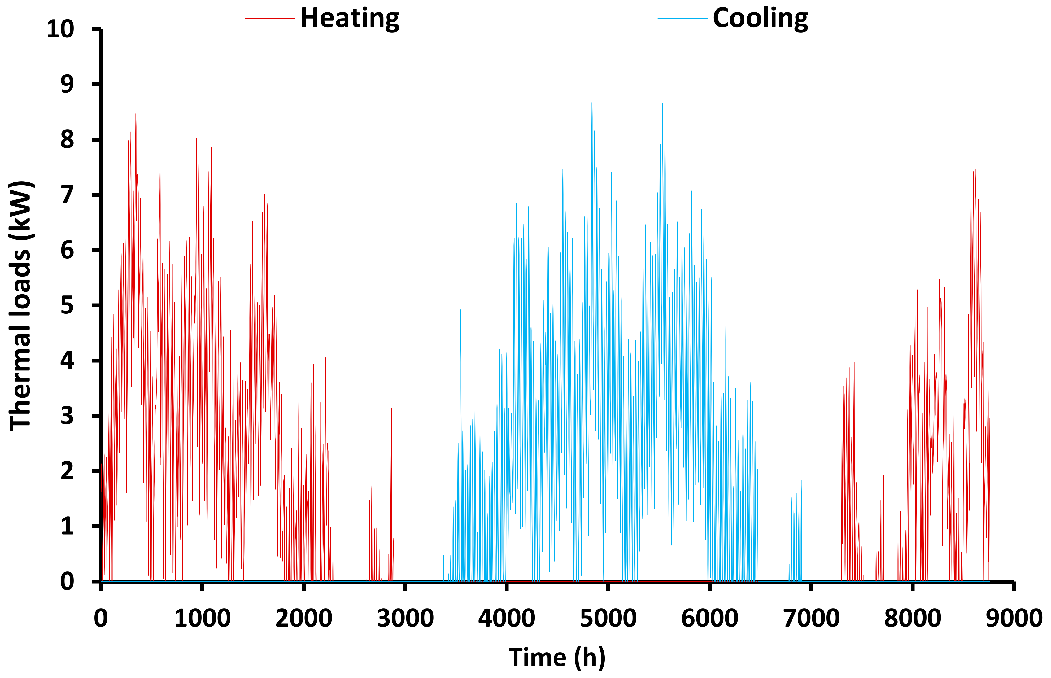
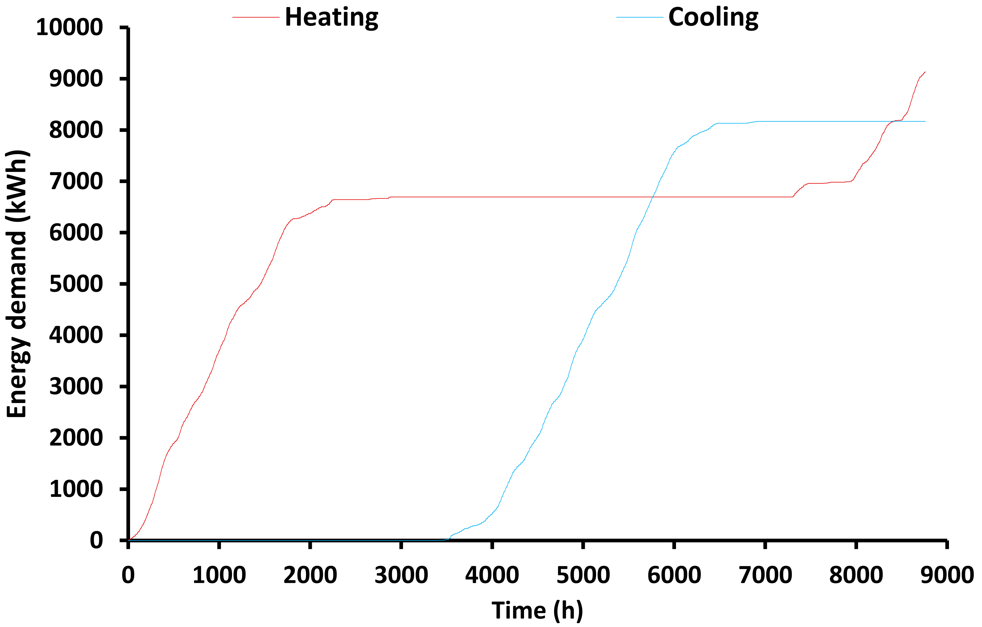
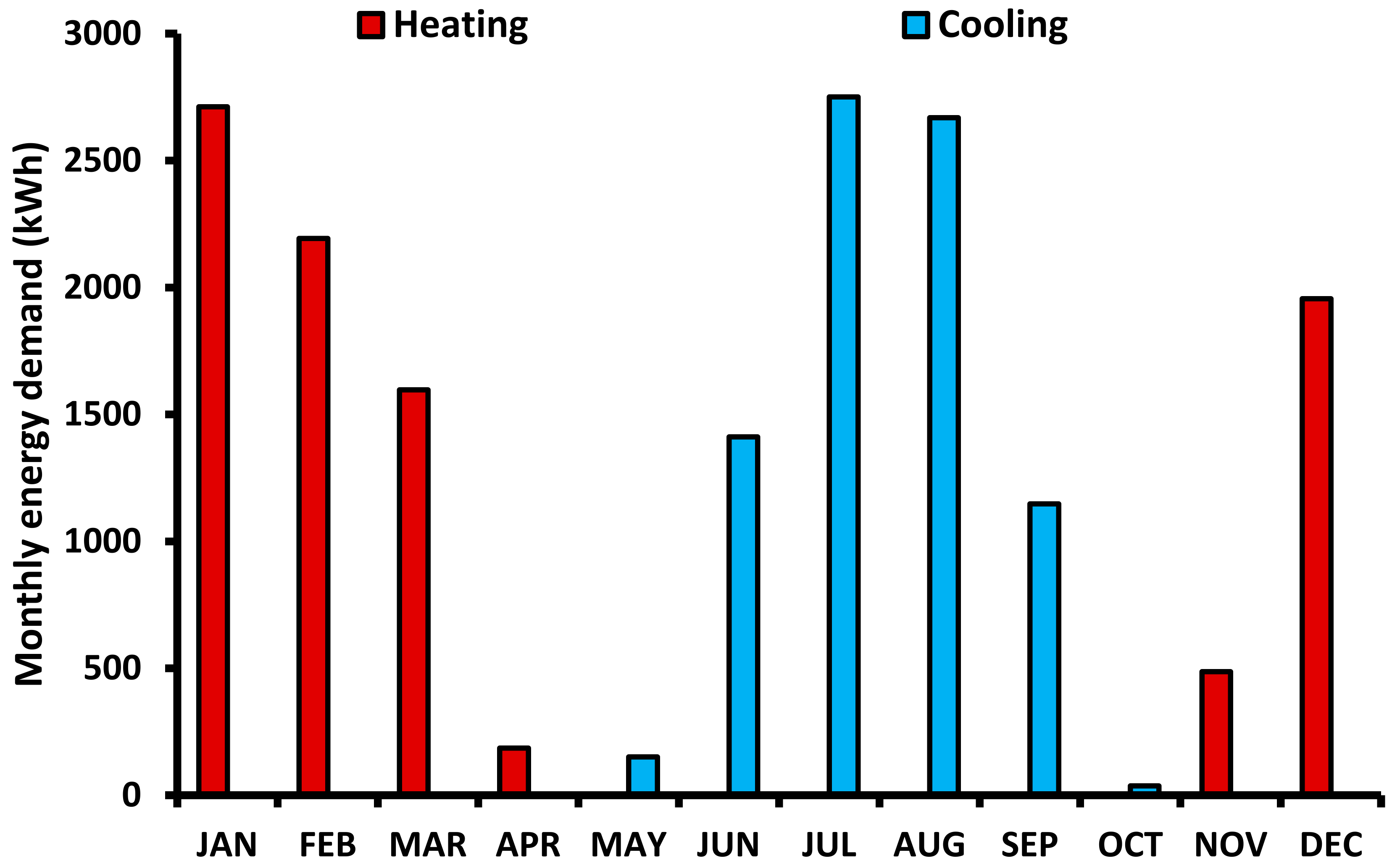
Biomass exploitation for covering the thermal loads of the buildings, both for heating and cooling, consists of a sustainable solution with multiple benefits. The present study suggested a novel system based on an absorption heat pump operating with the LiBr/water working pair. As a reference, a case study of a building with a 400 m2 floor area is examined in the location of Athens, Greece. The examined building presents specific heating and cooling loads at 22.84 kWh/m2 and 20.42 kWh/m2, respectively. The maximum heating loads were found in January and the maximum cooling load in July.
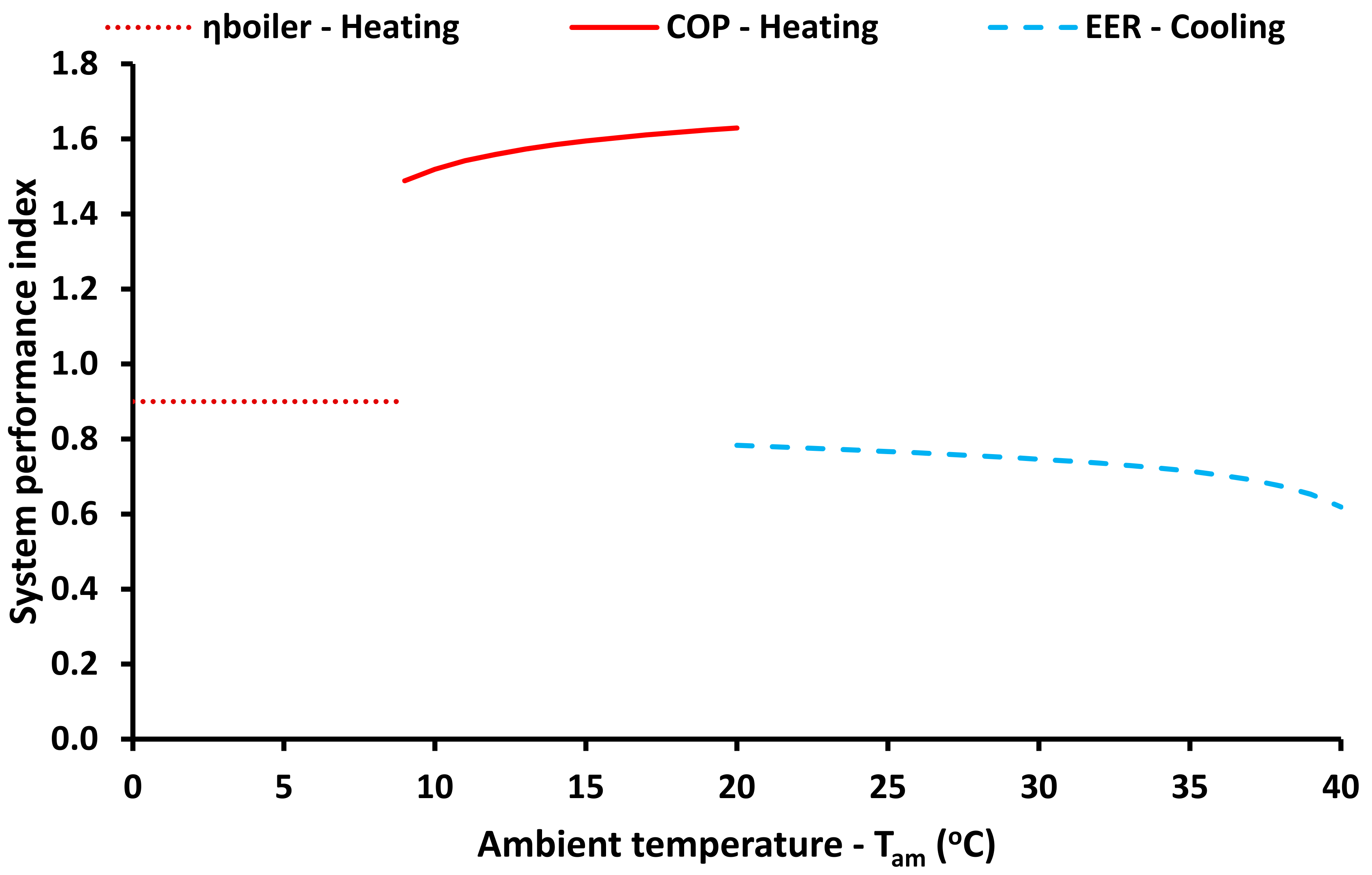
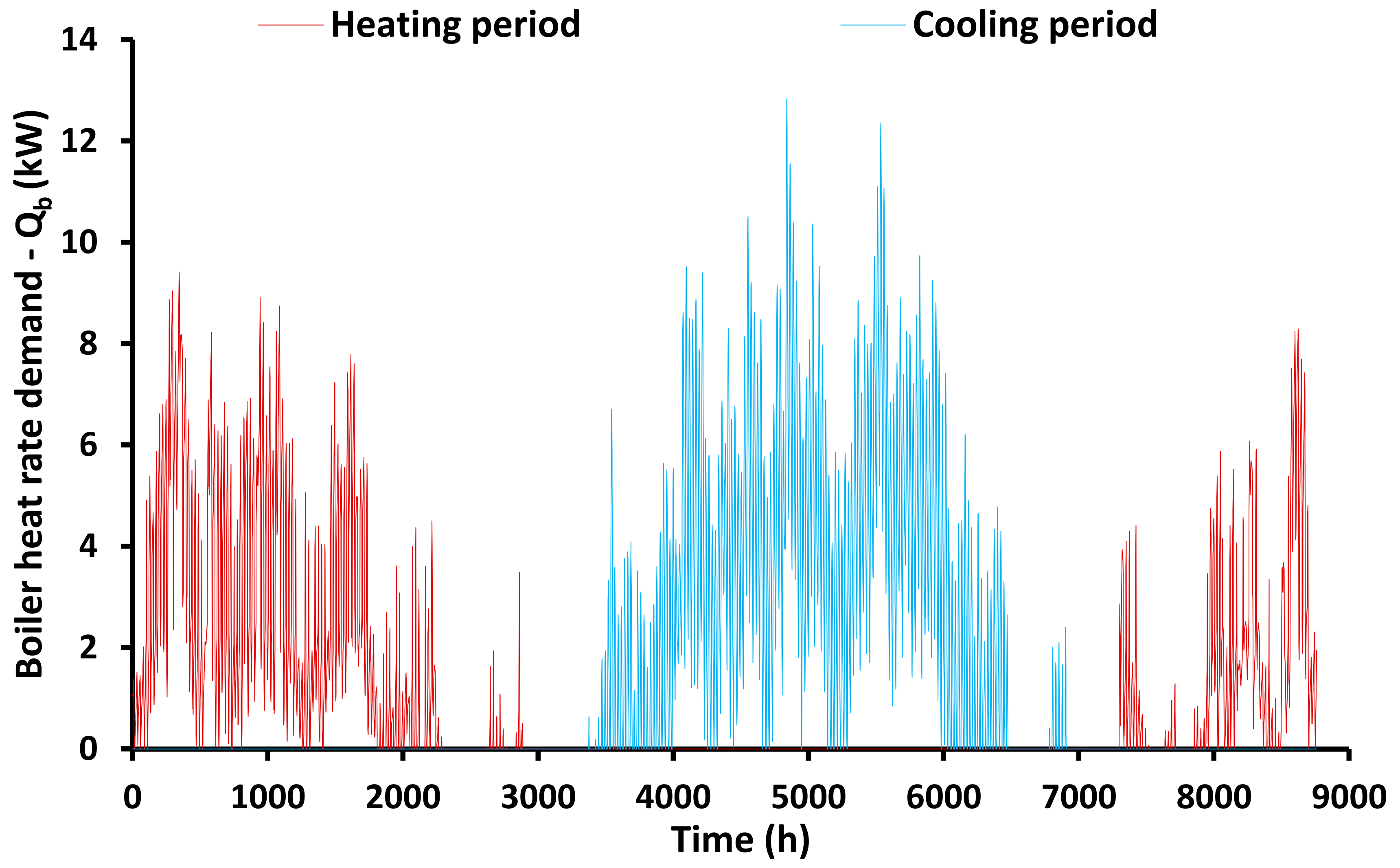
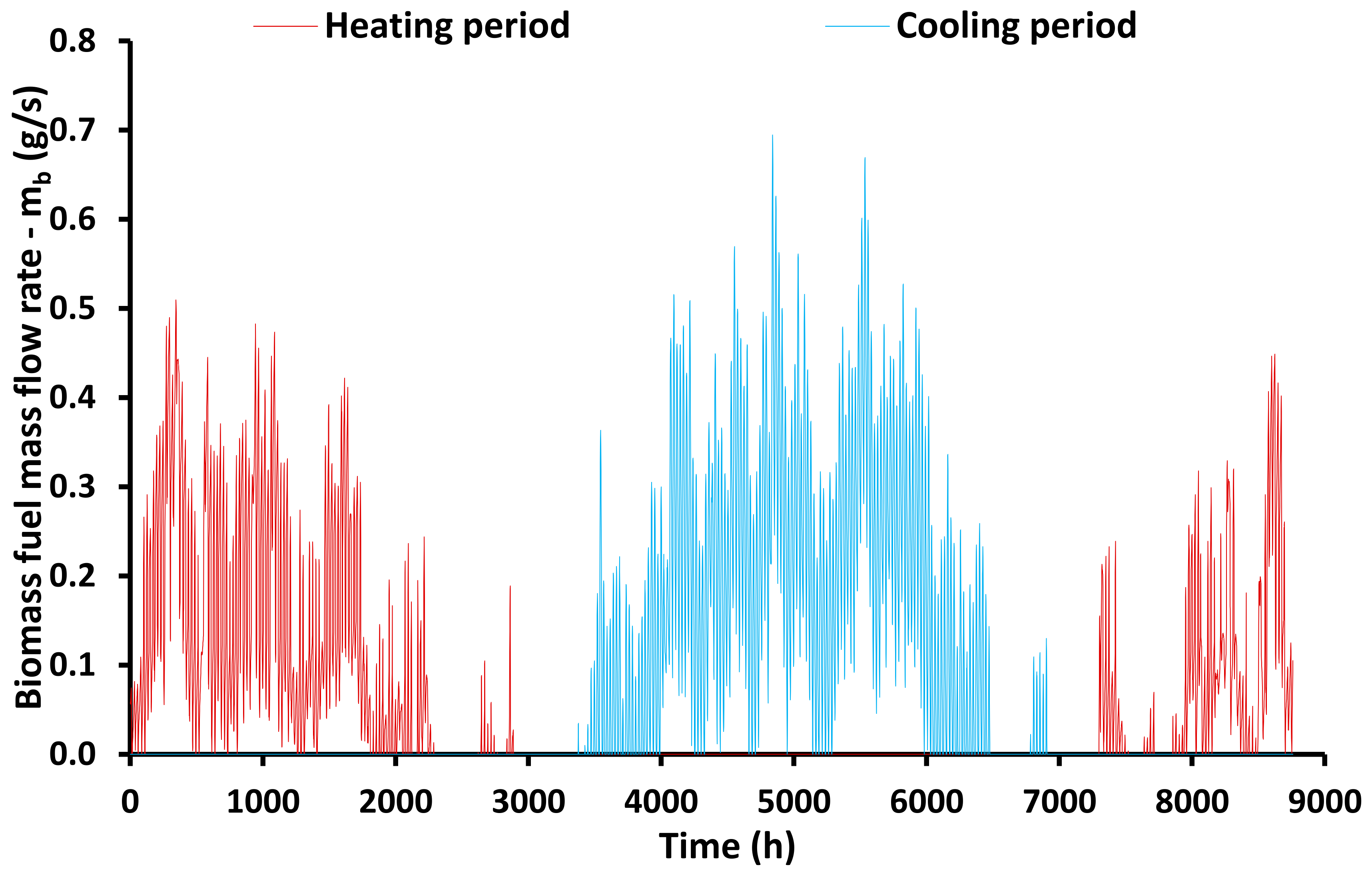
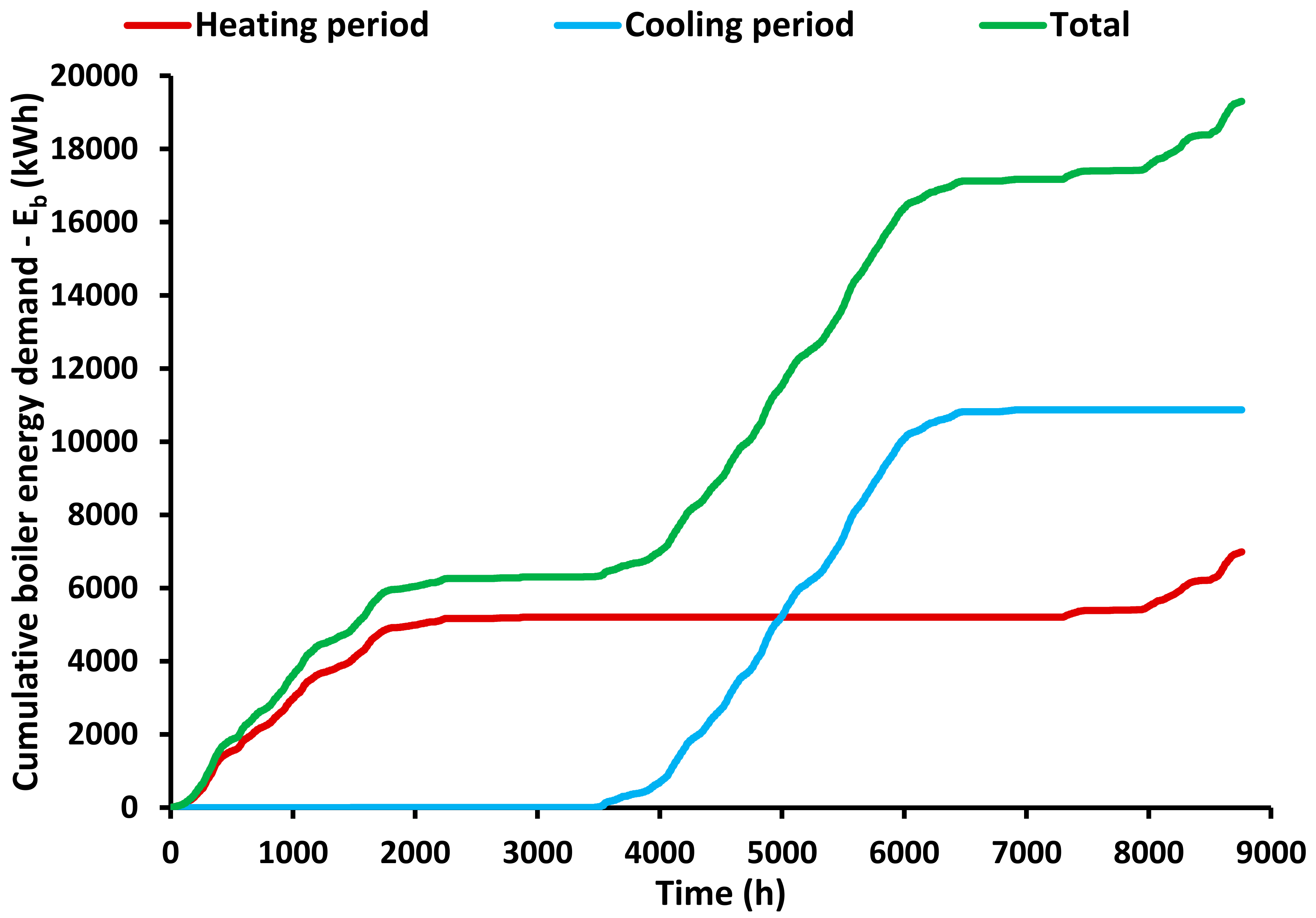
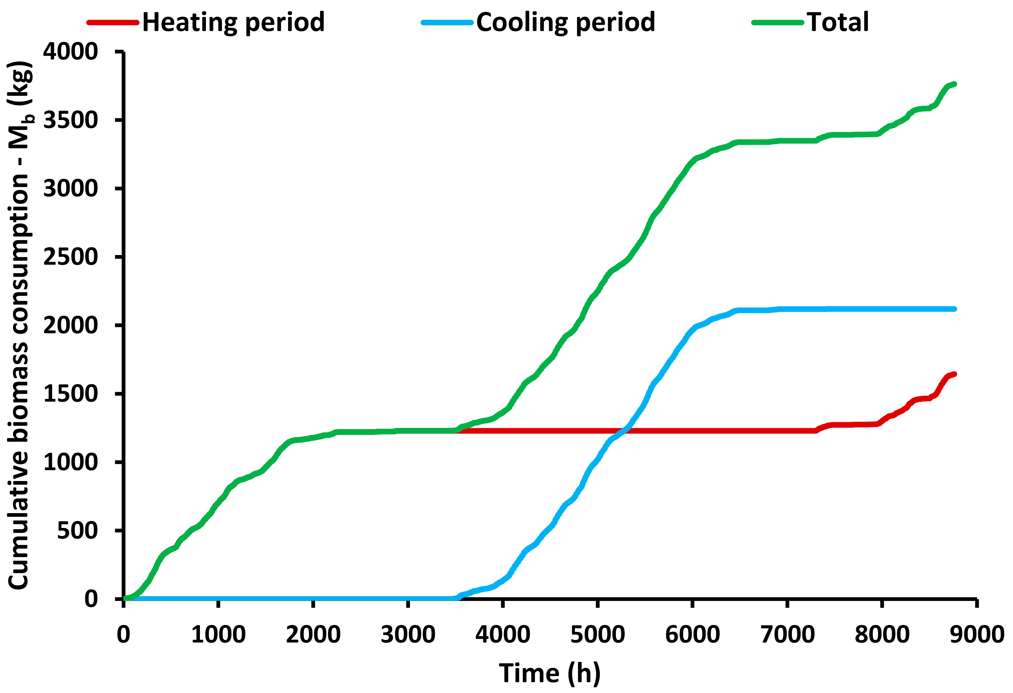
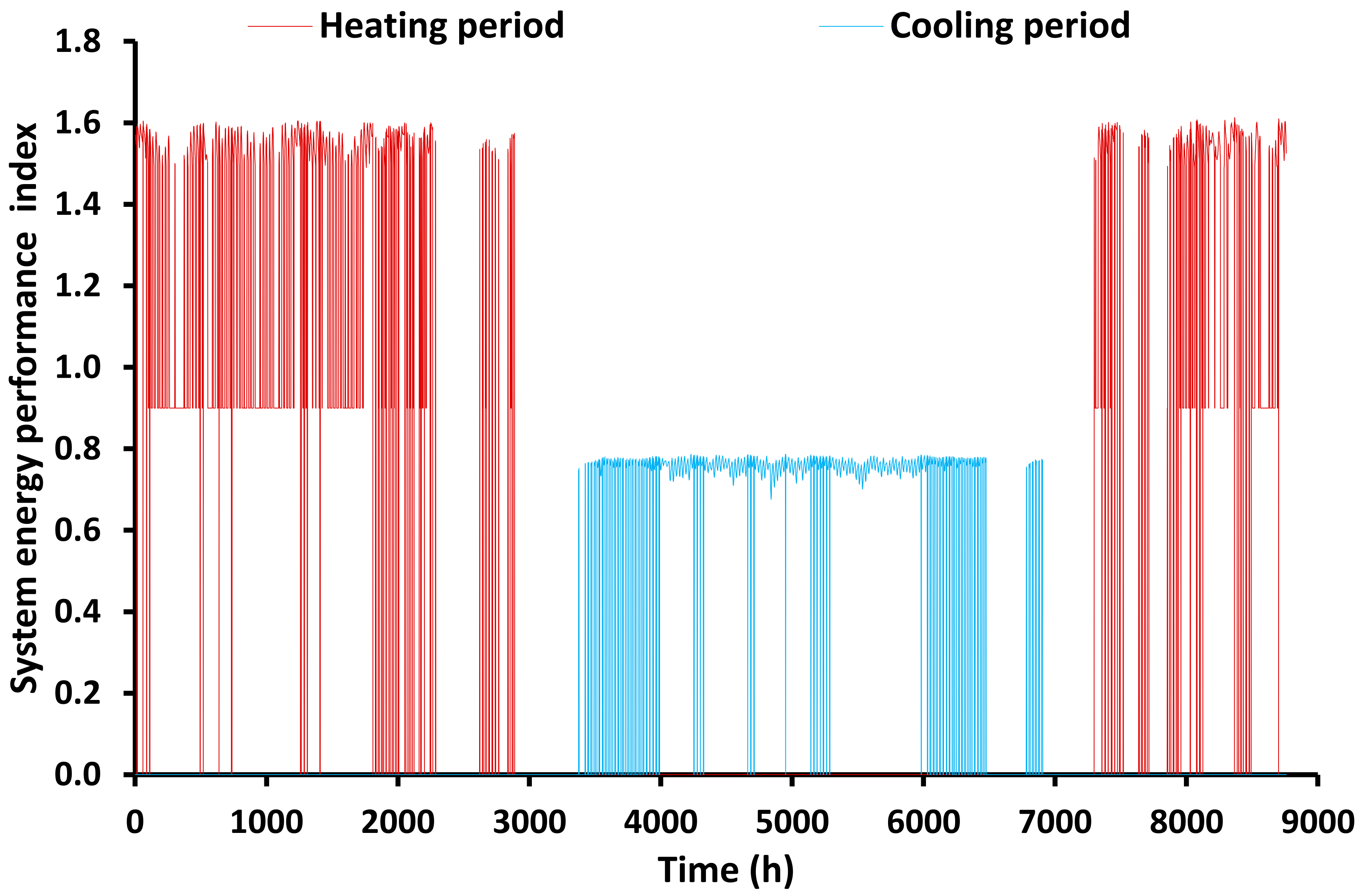
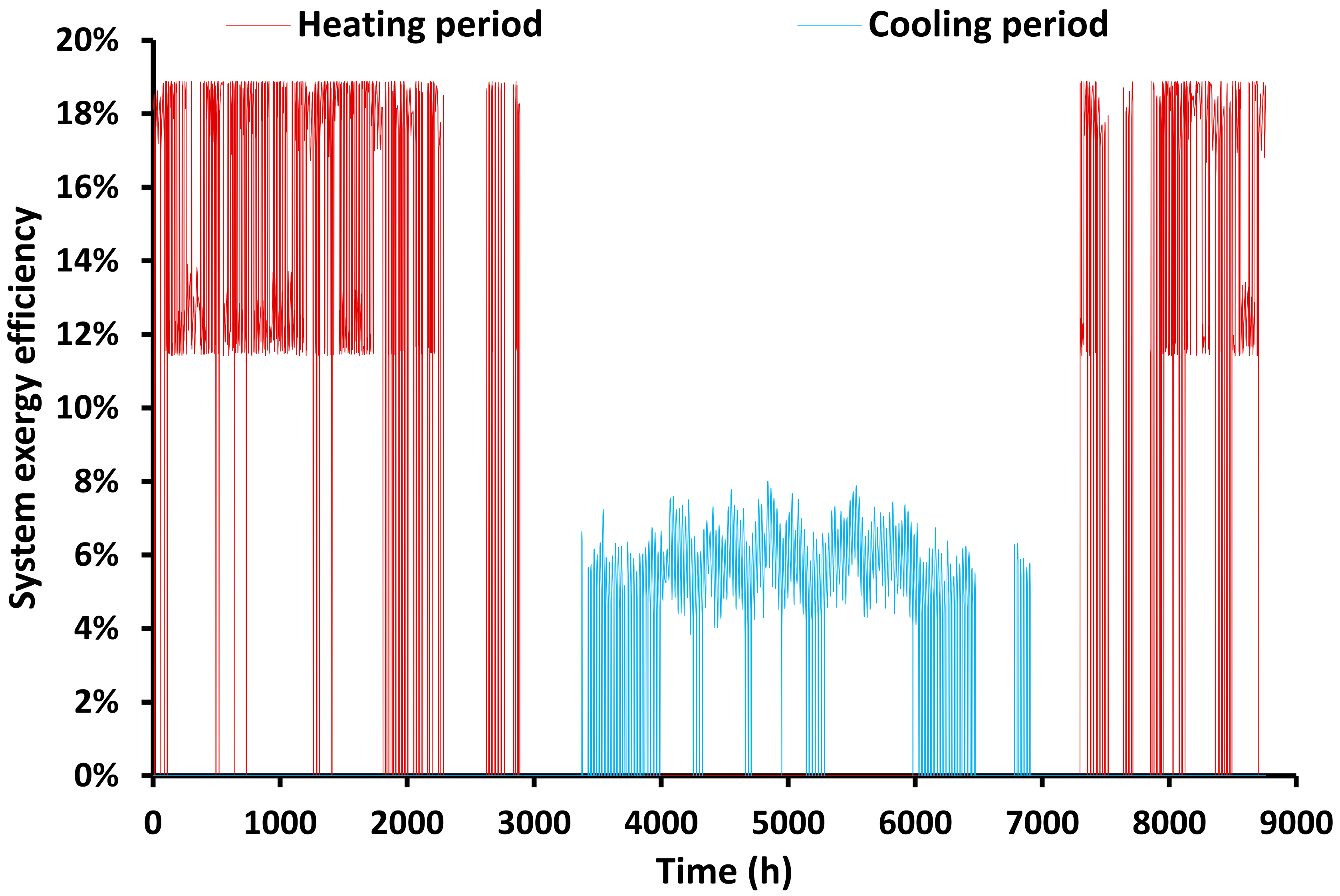
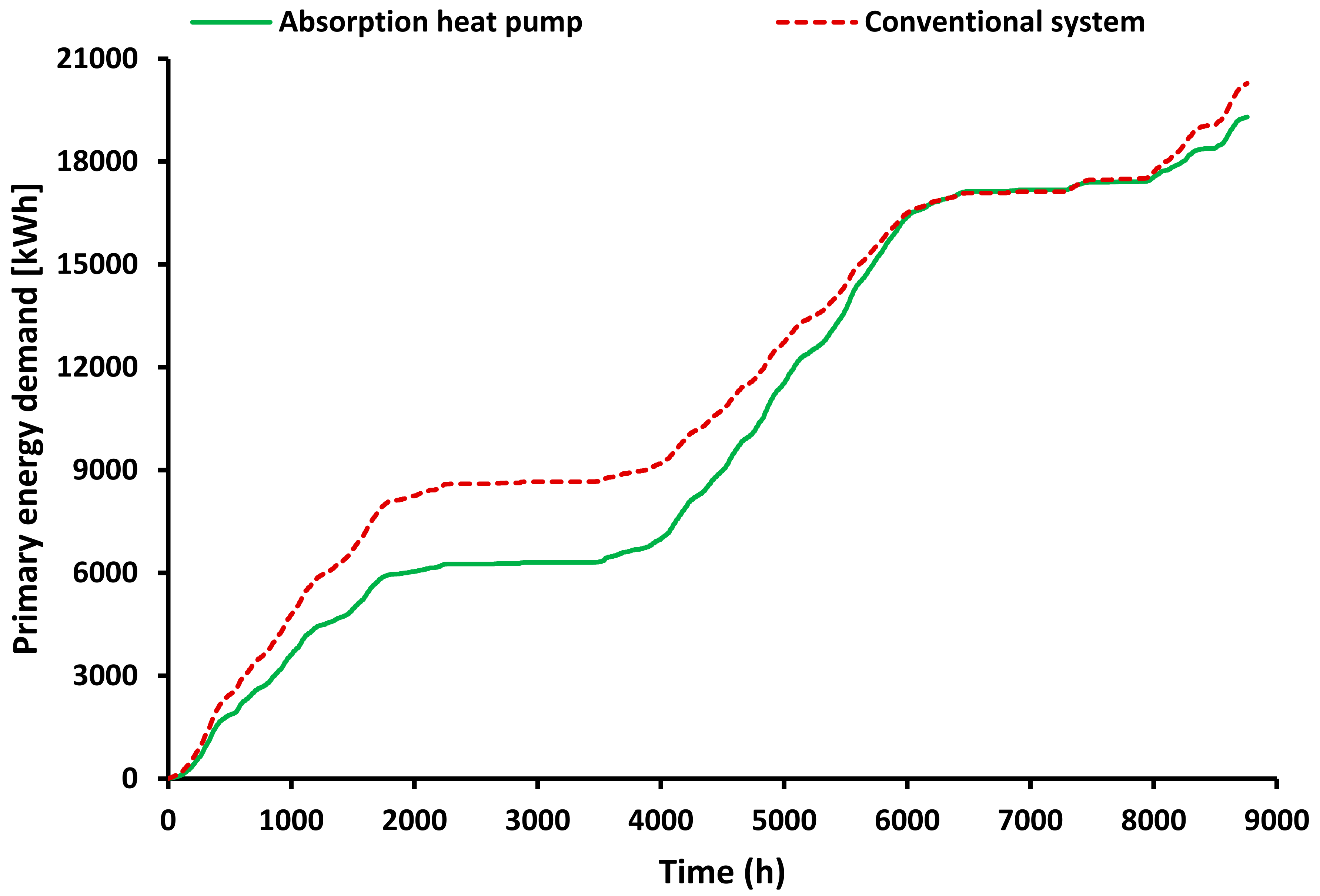
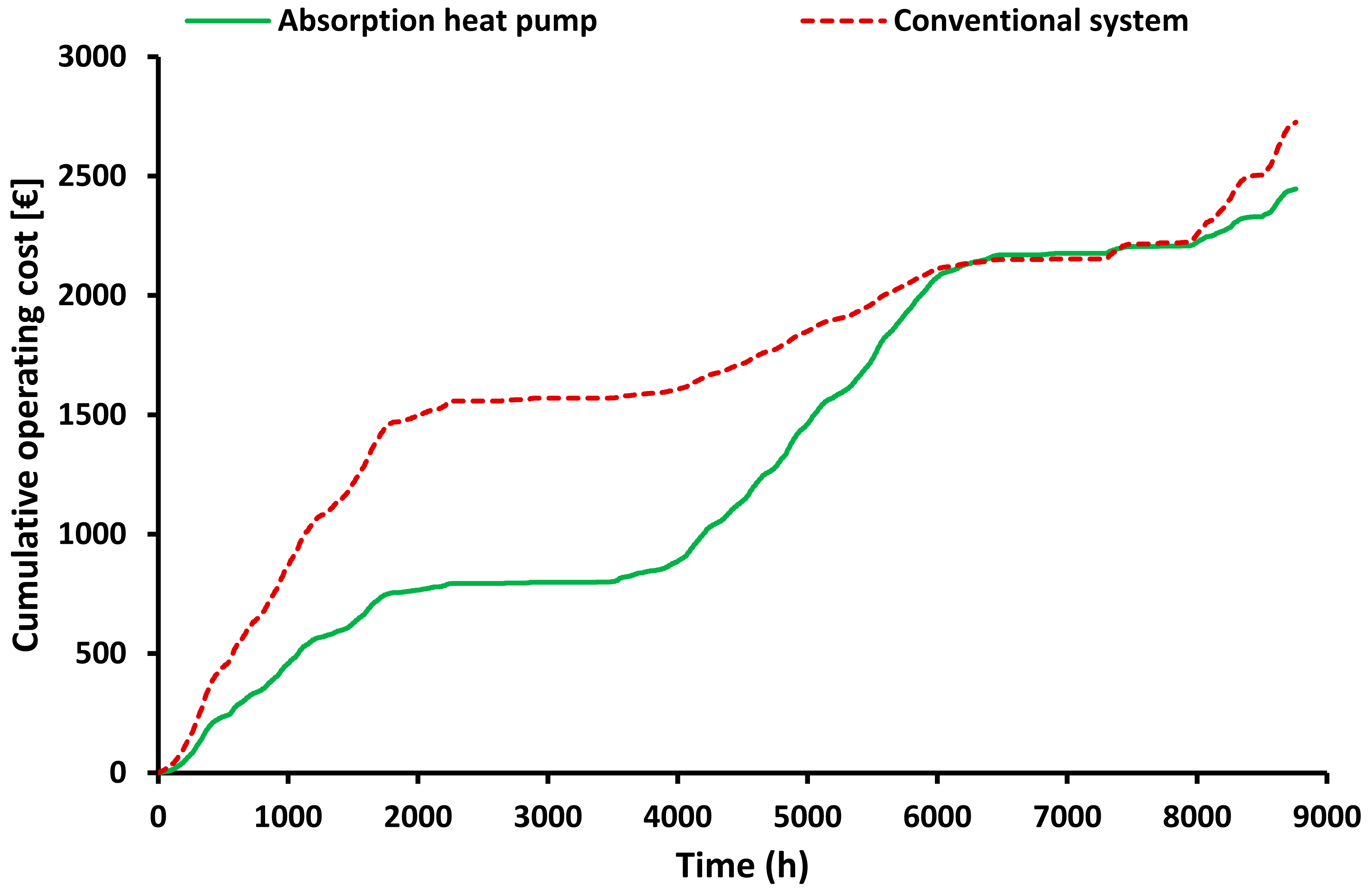
According to the simulation results, the total biomass energy demand was found to be a total of 17859 kWh and it is separated at 10870 kWh for cooling (61% of the total demand) and 6989 kWh for heating (39% of the total demand). Moreover, the yearly energy performance for heating is found to be 1.307, while the yearly energy performance for cooling is calculated at 0.751. The exergy efficiency of the heating period was found to be 14.48% and for the cooling period at 6.31%. Additionally, it is interesting to state that the cooling period of the system is 2627 h and the heating period is 3041 h. The heating period is separated into two parts; 63% with heat pump operation and 37% with the only boiler operation. It is important to highlight that the present system was found to be more efficient compared to another conventional system which operates with an oil boiler and electric heat pump. More specifically, a 10.3% decrease in the yearly operating cost was calculated, as well as 4.8% savings in primary energy were found. The CO2 avoidance was estimated at 4258 kgCO2 per year.
In the future, the examined system can be tested in different climate conditions, and also it can be evaluated financially in detail. Additionally, different working pairs can be tested and for example, the use of water/NH3 is a choice that has to be investigated. Lastly, the hybridization of the system with solar thermal systems, as well as the design of the system for domestic hot water production are extra ideas that have the potential for sustainable designs.

Author Contributions

E.B.: conceptualization, methodology, software, validation, formal analysis, investigation, writing—original draft preparation, writing—review and editing; P.L.: software, writing—original draft preparation; C.T.: writing—original draft preparation, supervision. All authors have read and agreed to the published version of the manuscript.

Funding

This research received no external funding.

Data Availability Statement

Data available after request.

Conflicts of Interest

The authors declare no conflict of interest.

Nomenclature

AArea, m2
cpSpecific heat capacity, J/kgK
COPcoolCooling coefficient of performance
COPheatHeating coefficient of performance
ExbExergy flow rate of the biomass heat rate, kW
hSpecific enthalpy, kJ/kg
hinIndoor heat convection coefficient, W/m2K
houtOutdoor heat convection coefficient, W/m2K
HHVHigh heating value of the biomass, kJ/kg
kThermal conductivity, W/mK
LLayer thickness, m
mbBiomass mass flow rate, kg/s
mrRefrigerant mass flow rate, kg/s
msStrong solution mass flow rate, kg/s
mwWeak solution mass flow rate, kg/s
NNumber of the layers in the examined structural element
QHeat rate, kW
TTemperature, °C or K
UThermal transmittance, W/m2K
XsStrong solution concentration in LiBr, %
XwWeak solution concentration in LiBr, %

Greek Symbols

ηboilerBoiler efficiency
ηen,coolEnergy efficiency for cooling
ηen,heatEnergy efficiency for heating
ηex,coolExergy efficiency for cooling
ηex,heatExergy efficiency for heating
ηHEXEffectiveness of the heat exchanger solution
ρDensity, kg/m3

Subscripts

absabsorber
amambient
am,crambient critical
bbiomass
concondenser
coolcooling
evapevaporator
framframe
gengenerator
glazglazing
heatheating
uuseful
windwindow

Abbreviation

PCMPhase Change Materials

References

  1. Seferlis, P.; Varbanov, P.S.; Papadopoulos, A.I.; Chin, H.H.; Klemeš, J.J. Sustainable design, integration, and operation for energy high-performance process systems. Energy 2021, 224, 120158. [Google Scholar] [CrossRef]
  2. European Commission. A Renovation Wave for Europe—Greening Our Buildings, Creating Jobs, Improving Lives; European Commission: Brusseles, Belgium, 2020. [Google Scholar]
  3. Frangou, M.; Aryblia, M.; Tournaki, S.; Tsoutsos, T. Renewable energy performance contracting in the tertiary sector Standardization to overcome barriers in Greece. Renew. Energy 2018, 125, 829–839. [Google Scholar] [CrossRef]
  4. Zhang, Y.; Li, L.; Xu, P.; Liu, B.; Shuai, Y.; Li, B. Hydrogen production through biomass gasification in supercritical water: A review from exergy aspect. Int. J. Hydrog. Energy 2019, 44, 15727–15736. [Google Scholar] [CrossRef]
  5. Zhang, Y.; Xu, P.; Liang, S.; Liu, B.; Shuai, Y.; Li, B. Exergy analysis of hydrogen production from steam gasification of biomass: A review. Int. J. Hydrog. Energy 2019, 44, 14290–14302. [Google Scholar] [CrossRef]
  6. Demirci, A.; Akar, O.; Ozturk, Z. Technical-environmental-economic evaluation of biomass-based hybrid power system with energy storage for rural electrification. Renew. Energy 2022, 195, 1202–1217. [Google Scholar] [CrossRef]
  7. Soltero, V.M.; Quirosa, G.; Peralta, M.E.; Chacartegui, R.; Torres, M. A biomass universal district heating model for sustainability evaluation for geographical areas with early experience. Energy 2022, 242, 122954. [Google Scholar] [CrossRef]
  8. Chen, Y.; Standl, P.; Weiker, S.; Gaderer, M. A general approach to integrating compression heat pumps into biomass heating networks for heat recovery. Appl. Energy 2022, 130, 118559. [Google Scholar] [CrossRef]
  9. Zhang, X.; Yang, J.; Fan, Y.; Zhao, X.; Yan, R.; Zhao, J.; Myers, S. Experimental and analytic study of a hybrid solar/biomass rural heating system. Energy 2020, 190, 116392. [Google Scholar] [CrossRef]
  10. Nami, H.; Anvari-Moghaddam, A.; Nemati, A. Modeling and analysis of a solar boosted biomass-driven combined cooling, heating and power plant for domestic applications. Sustain. Energy Technol. Assess. 2021, 47, 101326. [Google Scholar] [CrossRef]
  11. Bellos, E.; Vellios, L.; Theodosiou, I.-C.; Tzivanidis, C. Investigation of a solar-biomass polygeneration system. Energy Convers. Manag. 2018, 173, 283–295. [Google Scholar] [CrossRef]
  12. Tsimpoukis, D.; Syngounas, E.; Bellos, E.; Koukou, M.; Tzivanidis, C.; Anagnostatos, S.; Vrachopoulos, M.G. Investigation of energy and financial performance of a novel CO2 supercritical solar-biomass trigeneration system for operation in the climate of Athens. Energy Convers. Manag. 2021, 245, 114583. [Google Scholar] [CrossRef]
  13. Bellos, E.; Tzivanidis, C. Parametric Analysis of a Polygeneration System with CO2 Working Fluid. Appl. Sci. 2021, 11, 3215. [Google Scholar] [CrossRef]
  14. Xing, L.; Li, J. Proposal of biomass/geothermal hybrid driven poly-generation plant centering cooling, heating, power, and hydrogen production with CO2 capturing: Design and 3E evaluation. Fuel 2022, 330, 125593. [Google Scholar] [CrossRef]
  15. Rezaei, M.; Sameti, M.; Nasiri, F. An enviro-economic optimization of a hybrid energy system from biomass and geothermal resources for low-enthalpy areas. Energy Clim. Chang. 2021, 2, 100040. [Google Scholar] [CrossRef]
  16. Guo, J.; Liu, Z.; Yang, B.; Yang, X.; Yan, J. Melting assessment on the angled fin design for a novel latent heat thermal energy storage tube. Renew. Energy 2022, 183, 406–422. [Google Scholar] [CrossRef]
  17. Guo, J.; Wang, X.; Yang, B.; Yang, X.; Li, M.-J. Thermal assessment on solid-liquid energy storage tube packed with non-uniform angled fins. Sol. Energy Mater. Sol. Cells 2022, 236, 111526. [Google Scholar] [CrossRef]
  18. Mao, Q.; Hu, X.; Zhu, Y. Numerical Investigation of Heat Transfer Performance and Structural Optimization of Fan-Shaped Finned Tube Heat Exchanger. Energies 2022, 15, 5682. [Google Scholar] [CrossRef]
  19. Mo, C.; Zhang, G.; Yang, X.; Wu, X.; Li, X. A Battery Thermal Management System Coupling High-Stable Phase Change Material Module with Internal Liquid Cooling. Energies 2022, 15, 5863. [Google Scholar] [CrossRef]
  20. Borri, E.; Hua, N.; Sciacovelli, A.; Wu, D.; Ding, Y.; Li, Y.; Brancato, V.; Zhang, Y.; Frazzica, A.; Li, W.; et al. Phase Change Slurries for Cooling and Storage: An Overview of Research Trends and Gaps. Energies 2022, 15, 6873. [Google Scholar] [CrossRef]
  21. Available online: https://www.trnsys.com/ (accessed on 11 September 2022).
  22. F-Chart Software. Engineering Equation Solver (EES). 2015. Available online: https://www.fchart.com/ees (accessed on 11 September 2022).
  23. Bellos, E.; Tzivanidis, C. Performance analysis and optimization of an absorption chiller driven by nanofluid based solar flat plate collector. J. Clean. Prod. 2018, 174, 256–272. [Google Scholar] [CrossRef]
  24. Friedl, A.; Padouvas, E.; Rotter, H.; Varmuza, K. Prediction of heating values of biomass fuel from elemental composition. Anal. Chim. Acta 2005, 544, 191–198. [Google Scholar] [CrossRef]
  25. ΤOΤΕΕ 20701-1; Technical Guidelines on Buildings’ Energy Performance. Greek Technical Chamber: Athens, Greece, 2017.
  26. ISO 7730:2005; Ergonomics of the Thermal Environment—Analytical Determination and Interpretation of Thermal Comfort Using Calculation of the PMV and PPD Indices and Local Thermal Comfort Criteria. ISO: Geneva, Switzerland, 2005.
  27. Mitsopoulos, G.; Bellos, E.; Tzivanidis, C. Financial and Energetic Optimization of Greek Buildings Insulation. Designs 2018, 2, 34. [Google Scholar] [CrossRef] [Green Version]
  28. Gogoi, T.K.; Konwar, D. Exergy analysis of a H2O–LiCl absorption refrigeration system with operating temperatures estimated through inverse analysis. Energy Convers. Manag. 2016, 110, 436–447. [Google Scholar] [CrossRef]
  29. Compton, M.; Rezaie, B.; Rosen, M.A. Exergy approach for advancing sustainability of a biomass boiler. Int. J. Exergy 2018, 27, 62–80. [Google Scholar] [CrossRef]
  30. Bellos, E.; Tzivanidis, C.; Tsifis, G. Energetic, Exergetic, Economic and Environmental (4E) analysis of a solar assisted refrigeration system for various operating scenarios. Energy Convers. Manag. 2017, 148, 1055–1069. [Google Scholar] [CrossRef]
  31. Available online: https://trnsys.de/en/resources/faq/validation (accessed on 11 September 2022).
  32. Plytaria, M.T.; Bellos, E.; Tzivanidis, C.; Antonopoulos, K.A. Numerical simulation of a solar cooling system with and without phase change materials in radiant walls of a building. Energy Convers. Manag. 2019, 188, 40–53. [Google Scholar] [CrossRef]
  33. Bellos, E.; Tzivanidis, C. Energetic and financial analysis of solar cooling systems with single effect absorption chiller in various climates. Appl. Therm. Eng. 2017, 126, 809–821. [Google Scholar] [CrossRef]
  34. Bellos, E.; Tzivanidis, C. Energetic and financial sustainability of solar assisted heat pump heating systems in Europe. Sustain. Cities Soc. 2017, 33, 70–84. [Google Scholar] [CrossRef]
  35. Tzivanidis, C.; Bellos, E.; Mitsopoulos, G.; Antonopoulos, K.A.; Delis, A. Energetic and financial evaluation of a solar assisted heat pump heating system with other usual heating systems in Athens. Appl. Therm. Eng. 2016, 106, 87–97. [Google Scholar] [CrossRef]
  36. Bellos, E.; Tzivanidis, C.; Kouvari, A.; Antonopoulos, K.A. Comparison of Heating and Cooling Loads of a Typical Building with TRNSYS and eQUEST, Energy, Transportation and Global Warming; Springer: New York, NY, USA, 2016; pp. 327–338. [Google Scholar]
  37. Available online: https://www.dapeep.gr/ (accessed on 11 September 2022).
Figure 1. The examined absorption heat pump with LiBr/water working pair.
Asi 05 00099 g001
Figure 2. The examined system with the different operating modes.
Asi 05 00099 g002
Figure 3. Ambient temperature distribution during the year in Athens.
Asi 05 00099 g003
Figure 4. Variation of the thermal loads (heating and cooling) during the year for the examined building in Athens.
Asi 05 00099 g004
Figure 5. Cumulative thermal loads (heating and cooling) during the year for the examined building in Athens.
Asi 05 00099 g005
Figure 6. Monthly thermal loads (heating and cooling) for the examined building in Athens.
Asi 05 00099 g006
Figure 7. Performance of the absorption heat pump in different weather conditions.
Asi 05 00099 g007
Figure 8. Heat demand of the boiler during the year period, both for covering heating and cooling.
Asi 05 00099 g008
Figure 9. Consumption of biomass during the year period, both for covering heating and cooling.
Asi 05 00099 g009
Figure 10. The cumulative energy demand of the biomass for heating, cooling, and total.
Asi 05 00099 g010
Figure 11. The cumulative biomass consumption for heating, cooling, and total.
Asi 05 00099 g011
Figure 12. System energy performance during the heating and cooling periods.
Asi 05 00099 g012
Figure 13. System exergy efficiency during the heating and cooling periods.
Asi 05 00099 g013
Figure 14. Cumulative primary energy demand with the absorption heat pump and the conventional system during the year period.
Asi 05 00099 g014
Figure 15. Cumulative operating cost with the absorption heat pump and the conventional system during the year period.
Asi 05 00099 g015
Table 1. Parameters of the system simulation.
ParameterValue
Evaporator temperature in cooling mode5 °C
Condenser/absorber temperature in heating mode50 °C
Generator temperature110 °C
Solution heat exchanger effectiveness70%
Temperature pinch point in the evaporator5 K
Temperature pinch point in the absorber/condenser10 K
Boiler nominal efficiency90% [11]
Higher heating value of the biomass18467 kJ/kg [24]
Table 2. Composition of the structural elements and material thermal properties.
Structural ComponentMaterialsThickness (cm)k
(W/mK)
ρ
(kg/m3)
cp
(J/kgK)
RoofConcrete252.12400800
Insulation100.03540800
GroundFloor10.078001000
Concrete252.12400800
Insulation100.03540800
WallPlaster11.38920001000
Brick120.88918001000
Insulation80.03540800
Brick120.88918001000
Plaster11.38920001000
Table 3. Information for the examined building.
ParameterValue
Heating set point20 °C
Cooling set point26 °C
Floor area400 m2
Length20 m
Width20 m
Height3 m
South window total area10 m2
Infiltration and natural ventilation1 air change per hour
Appliances and lighting specific gain7 W/m2
Occupants7 persons sited in rest
Specific load per occupant100 W/occupant (ISO 7730) [26]
U-values of the ground0.304 W/m2K
U-value of the roof0.318 W/m2K
U-value of the external walls0.365 W/m2K
U-value of the glazing (85% of the window)2.80 W/m2K
U-value of the frame (15% of the window)2.27 W/m2K
U-value of the window2.72 W/m2K
g-value of the window0.755
Table 4. Monthly thermal loads for the examined building in Athens.
MonthHeating (kWh)Cooling (kWh)
January27120
February21930
March15970
April1860
May5151
June01412
July02751
August02669
September01148
October037
November4870
December19560
Year91368168
Table 5. Final results of the yearly performance.
ParameterValue
Cooling load8168 kWh
Heating load9136 kWh
Biomass demand for cooling10870 kWh
Biomass demand for heating6989 kWh
Total biomass demand17859 kWh
Mass of the consumed biomass for cooling2119 kg
Mass of the consumed biomass for heating1644 kg
The total mass the consumed biomass3763 kg
Yearly system cooling energy performance0.751
Yearly system heating energy performance1.307
Yearly exergy efficiency for cooling6.31%
Yearly exergy efficiency for heating14.48%
Cooling period2627 h
Heating period3041 h
Heating period without heat pump operation1126 h
Heating period with heat pump operation1915 h
Publisher’s Note: MDPI stays neutral with regard to jurisdictional claims in published maps and institutional affiliations.

