
Laser Beam Welding under Vacuum of Hot-Dip Galvanized Constructional Steel
 , ,
, ,
Abstract
:1. Introduction
2. State of Art
2.1. Hot-Dip Galvanizing
2.2. Laser Welding
3. Setup
4. Results and Discussion
5. Conclusions
Author Contributions
Funding
Data Availability Statement
Conflicts of Interest
References
- Börner, C.; Krüssel, T.; Dilger, K. Process characteristics of laser beam welding at reduced ambient pressure. In High-Power Laser Materials Processing: Lasers, Beam Delivery, Diagnostics, and Applications II; Dorsch, F., Ed.; SPIE: Bellingham, DC, USA, 2013; pp. 1–13. [Google Scholar]
- Ungermann, D.; Holtkamp, S.; Rademacher, D.; Hechler, O.; Pinger, T. Anwendung der Feuerverzinkung im Brückenbau. In STAHLBAU KALENDER 2017: Dauerhaftigkeit Ingenieurtragwerke; Kuhlmann, U., Ed.; Wiley: Hoboken, NJ, USA, 2017; pp. 767–812. [Google Scholar]
- Pinger, T. Zur Vermeidung der Rissbildung an Stahlkonstruktionen beim Feuerverzinken Unter Besonderer Berücksichtigung der Flüssigmetallinduzierten Spannungsrisskorrosion. Ph.D. Thesis, Shaker, Aachen, Germany, 2009. [Google Scholar]
- BASt—Bundesanstalt für Straßenwesen. Zusätzliche Technische Vertragsbedingungen und Richtlinien für Ingenieurbauten (ZTV-ING); Bundesministerium für Digitales und Verkehr: Bonn, Germany, 2022. [Google Scholar]
- Jakobs, S. Laserstrahlschweißen im Vakuum: Erweiterung der Prozessgrenzen für Dickwandige Bleche. Ph.D. Thesis, Shaker Verlag, Herzogenrath, Germany, 2015. [Google Scholar]
- Gerhards, B.; Schleser, M.; Otten, C. Laser beam welding with mobile vacuum: MoVac. In High-Power Laser Materials Processing: Applications, Diagnostics, and Systems X; Kaierle, S., Heinemann, S.W., Eds.; SPIE: Bellingham, DC, USA, 2021; p. 6. [Google Scholar]
- Thiele, M.; Schütz, A.; Schulz, W.D. Struktur und Eigenschaften von Zinküberzügen Nach DIN EN ISO 1461 Aus Legierten Zinkschmelzen in Abhängigkeit vom Si-Gehalt des Stahlwerkstoffes, den Verzinkungsbedingungen und den Abkühlbedingungen; AiF: Dresden, Germany, 2008. [Google Scholar]
- Stahl-Informations-Zentrum. Merkblatt 400-Korrosionsverhalten von Feuerverzinktem Stahl, 6th ed.; Stahl-Zentrum: Düsseldorf, Germany, 2001. [Google Scholar]
- Schulz, W.-D.; Thiele, M. Feuerverzinken von Stückgut, 2nd ed.; Leuze-Verlag: Bad Saulgau, Germany, 2012. [Google Scholar]
- DIN EN ISO 14713:(14713); Leitfäden und Empfehlungen zum Schutz von Eisen- und Stahlkonstruktionen vor Korrosion. Deutsches Institut für Normung e. V.: Berlin, Germany, 2020.
- Lappalainen, E.; Unt, A.; Sokolov, M.; Vänskä, M.; Salminen, A. Laser welding with high power Lasers: The effect of joint configuration. In Proceedings of the 14th NOLAMP Conference: The 14th Nordic Laser Materials Processing Conference, Gothenburg, Sweden, 26–28 August 2013; Luleå University of Technology, Department of Engineering Sciences and Mathematics, Division of Product and Production Development: Luleå, Sweden, 2013; pp. 133–144. [Google Scholar]
- Sokolov, M.; Salminen, A.; Katayama, S.; Kawahito, Y. Reduced pressure laser welding of thick section structural steel. J. Mater. Process. Technol. 2015, 219, 278–285. [Google Scholar] [CrossRef]
- Feldmann, M.; Pinger, T.; Schäfer, D.; Pope, R.; Smith, W.; Sedlacek, G. Hot-Dip-Zinc-Coating of Prefabricated Structural Steel Components; Italien: Aachen, Germany, 2010. [Google Scholar]
- Arata, Y.; Abe, N.; Oda, T.; Tsujii, N. Fundamental phenomena during vacuum laser welding. ICALEO Proc. 1984, 44, 1–7. [Google Scholar] [CrossRef]
- Abe, Y.; Mizutani, M.; Kawahito, Y.; Katayama, S. Deep penetration welding with high power laser under vacuum. Int. Congr. Appl. Lasers Electro-Opt. 2010, 2010, 648–653. [Google Scholar] [CrossRef]
- Katayama, S.; Kobayashi, Y.; Mizutani, M.; Matsunawa, A. Effect of vacuum on penetration and defects in laser welding. J. Laser Appl. 2001, 13, 187–192. [Google Scholar] [CrossRef]
- Reisgen, U.; Olschok, S.; Jakobs, S. Laser beam welding under vacuum in comparison to electron beam welding. Weld. Cut. 2010, 9, 224–230. [Google Scholar]
- Turner, C. Erweiterung der Anwendungsfelder des Laserstrahlschweißens im Vakuum auf Duplex-Stahl und Kupfer. Ph.D. Thesis, Rheinisch-Westfälische Technische Hochschule Aachen, Aachen, Germany, 2019. [Google Scholar]
- Jiang, M.; Tao, W.; Chen, Y. Laser Welding under Vacuum: A Review. Appl. Sci. 2017, 7, 909. [Google Scholar] [CrossRef]
- Keitel, S.; Kocks, H.-J.; Raschke, A. Einsatz des Laserstrahlschweißens beim Bau Einer Gaspipeline. DVS Berichte 2018, 344, 161–166. [Google Scholar]
- Hao, Y.; Wang, H.-P.; Sun, Y.; Li, L.; Wu, Y.; Lu, F. The evaporation behavior of zinc and its effect on spattering in laser overlap welding of galvanized steels. J. Mater. Process. Technol. 2022, 306, 117625. [Google Scholar] [CrossRef]
- Zhang, Z.; Zhao, Y.; Wu, S.; Lu, H. Optimization of butt welding of zinc-coated thin sheets with oscillating fiber laser beams: Weld formation, microstructure, and mechanical properties. Weld World 2021, 65, 1711–1723. [Google Scholar] [CrossRef]
- Roos, C.; Schmidt, M. Remote Laser Welding of Zinc Coated Steel Sheets in an Edge Lap Configuration with Zero Gap. Phys. Procedia 2014, 56, 535–544. [Google Scholar] [CrossRef]
- Górka, J.; Suder, W.; Kciuk, M.; Stano, S. Assessment of the Laser Beam Welding of Galvanized Car Body Steel with an Additional Organic Protective Layer. Materials 2023, 16, 670. [Google Scholar] [CrossRef] [PubMed]
- Rezeznikiewicz, A.; Górka, J.; Przybyla, M.; Kciuk, M. Assessment of properties and corrosion resistence of galvanized steel welded with laser beam. Int. J. Mod. Manuf. Technol. 2023, XV, 155–166. [Google Scholar]
- Honig, R.E.; Krammer, D.A. Vapor data pressure for the solid and the liquid elements. RCA Rev. 1969, 30, 285–305. [Google Scholar]
- Jakobs, S.; Reisgen, U.; Olschok, S.; Klein, S. Unterdruckkammer Mit Einem Schutzgehäuse (DE 10 2014 103 635 A1); Deutsches Patent- und Markenamt: München, Germany, 2015. [Google Scholar]
- DIN EN 10025-4; Warmgewalzte Erzeugnisse aus Baustählen-Teil 4. Deutsches Institut für Normung e. V.: Berlin, Germany, 2023.
- DIN EN ISO 1461; Durch Feuerverzinken Auf Stahl Aufgebrachte Zinküberzüge (Stückverzinken). Deutsches Institut für Normung e. V.: Berlin, Germany, 2022.
- Wagner, J.; Hagenlocher, C.; Hummel, M.; Olowinsky, A.; Weber, R.; Graf, T. Synchrotron X-ray Analysis of the Influence of the Magnesium Content on the Absorptance during Full-Penetration Laser Welding of Aluminum. Metals 2021, 11, 797. [Google Scholar] [CrossRef]
- Zhang, C.; Li, X.; Gao, M. Effects of circular oscillating beam on heat transfer and melt flow of laser melting pool. J. Mater. Res. Technol. 2020, 9, 9271–9282. [Google Scholar] [CrossRef]
- DIN EN ISO 14713-2; Zinküberzüge–Leitfäden und Empfehlungen zum Schutz von Eisen-und Stahlkonstruktionen vor Korrosion-Teil 2. Deutsches Institut für Normung e. V.: Berlin, Germany, 2022.
- Hollmann, P.; Drechsel, J.; Zenker, R.; Löschner, U.; Biermann, H. Comparative Studies on Electron Beam and Laser Beam Welding of QT-Steel and Structural Steel. HTM J. Heat Treat. Mater. 2019, 74, 331–341. [Google Scholar] [CrossRef]


| C [wt%] | Si [wt%] | Mn [wt%] | P [wt%] | S [wt%] | Cr [wt%] | Nb [wt%] | Ti [wt%] | V [wt%] | Residual [wt%] | |
|---|---|---|---|---|---|---|---|---|---|---|
| S355M | 0.771 | 0.377 | 1.580 | 0.013 | 0.003 | 0.043 | 0.033 | 0.015 | 0.033 | 0.055 |
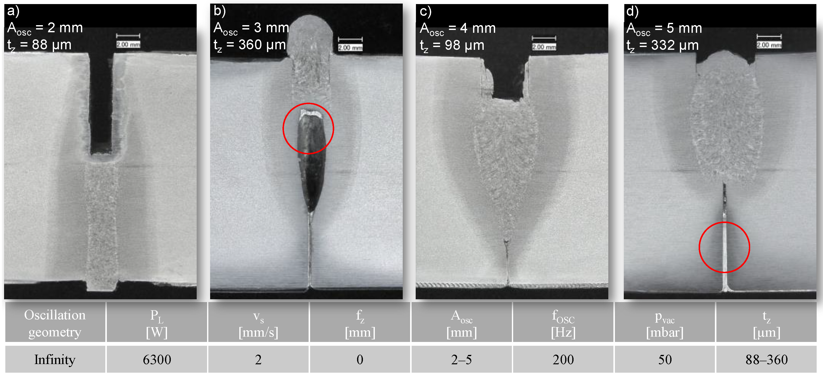
| Line | Circle | Infinity | Triangle | |
|---|---|---|---|---|
| Aosc[mm] | 1–5 | 0.3–5 | 2–5.5 | 4 |
| fosc[Hz] | 200 | 30–200 | 50–300 | 200 |
Disclaimer/Publisher’s Note: The statements, opinions and data contained in all publications are solely those of the individual author(s) and contributor(s) and not of MDPI and/or the editor(s). MDPI and/or the editor(s) disclaim responsibility for any injury to people or property resulting from any ideas, methods, instructions or products referred to in the content. |
© 2024 by the authors. Licensee MDPI, Basel, Switzerland. This article is an open access article distributed under the terms and conditions of the Creative Commons Attribution (CC BY) license (https://creativecommons.org/licenses/by/4.0/).
Share and Cite
Frey, C.; Stocks, O.; Olschok, S.; Kühne, R.; Feldmann, M.; Reisgen, U. Laser Beam Welding under Vacuum of Hot-Dip Galvanized Constructional Steel. J. Manuf. Mater. Process. 2024, 8, 17. https://doi.org/10.3390/jmmp8010017
Frey C, Stocks O, Olschok S, Kühne R, Feldmann M, Reisgen U. Laser Beam Welding under Vacuum of Hot-Dip Galvanized Constructional Steel. Journal of Manufacturing and Materials Processing. 2024; 8(1):17. https://doi.org/10.3390/jmmp8010017
Chicago/Turabian StyleFrey, Christian, Ole Stocks, Simon Olschok, Ronny Kühne, Markus Feldmann, and Uwe Reisgen. 2024. "Laser Beam Welding under Vacuum of Hot-Dip Galvanized Constructional Steel" Journal of Manufacturing and Materials Processing 8, no. 1: 17. https://doi.org/10.3390/jmmp8010017