Article

Investigation of Metal Wire Mesh as Support Material for Dieless Forming of Woven Reinforcement Textiles †

by
Jan-Erik Rath
* and
Thorsten Schüppstuhl
Institute of Aircraft Production Technology, Hamburg University of Technology, Denicketsr. 17, 21073 Hamburg, Germany
*
Author to whom correspondence should be addressed.
This article is an extended version of the conference paper Rath, J.-E.; Schüppstuhl, T. Die-less forming of fiber-reinforced thermoplastic sheets and metal wire mesh. In Sheet Metal 2023. 20th International Conference on Sheet Metal, Erlangen-Nürnberg, Germany, 2–5 April; Merklein, M., Hagenah, H., Duflou, J.R., Fratini, L., Martins, P., Meschut, G., Micari, F., Eds.; Materials Research Forum LLC, 2023; pp. 37–44, https://doi.org/10.21741/9781644902417-5.
J. Manuf. Mater. Process. 2023, 7(5), 182; https://doi.org/10.3390/jmmp7050182
Submission received: 23 August 2023 / Revised: 5 October 2023 / Accepted: 9 October 2023 / Published: 11 October 2023

Abstract

:
Within the rapidly growing market for fiber-reinforced plastics (FRPs), conventional production processes involving molds are not cost-efficient for prototype and small series production. Therefore, new flexible forming techniques are increasingly being researched, many of which have been inspired by incremental sheet metal forming (ISF). Due to the different deformation mechanisms of woven reinforcement fibers and metal sheets, ISF is not directly applicable to FRP. Instead, shear and bending of the fibers need to be realized. Therefore, a new dieless forming process for the production of FRP supported by metal wire mesh as an auxiliary material is proposed. Two standard tools, such as hemispherical punches, are used to locally bend a reversible layup of metal wire mesh and woven reinforcement fiber fabric enclosed in a vacuum bag. Therefore, the mesh aids in introducing shear into the material due to its ability to transmit compressive in-plane forces, and it ensures that the otherwise flexible fabric maintains the intended deformation until the part is cured or solidified. Basic experiments are conducted using thermoset prepreg, woven commingled yarn fabric, and thermoplastic organo sheets, proving the feasibility of the approach.

1. Introduction

Fiber-reinforced plastics (FRPs) are an essential material to achieve weight reduction and performance optimization goals in many products. Thus, they are increasingly used in aviation, the automotive industry, sports, and medical applications. Reinforcement fibers from carbon, glass, aramid, or natural materials are often supplied as woven textiles combining the good trade-off between reinforcing effects and drapability [1]. As an embedding and shaping matrix, thermoset and thermoplastic polymers can be used. While thermosets allow an easier impregnation of the fibers due to their lower viscosity, thermoplastics are reshapable, weldable, and more easily recyclable [2,3,4,5].
Typical manufacturing processes of thermoset FRP parts include injection or resin transfer molding, autoclave processes, and hand layup. Either initially separate fiber fabrics and matrix or pre-impregnated fabrics (prepregs) are used. The material is placed in an open, closed, or vacuum-bagged mold before resin is applied or injected, if necessary, and cured [4,6]. Due to the higher viscosity of thermoplastic polymers, their composite parts are usually manufactured from pre-impregnated and consolidated semi-finished products, called organo sheets, in thermoforming processes. Therefore, the sheet is heated above the thermoplastic’s glass transition or melting temperature and then formed in a press [4,7].
All the abovementioned processes require at least one mold, usually accompanied by high development efforts and investment costs [8,9]. Most prototyping processes, especially hand layup, depend upon considerable manual work, including fabric draping, vacuum bagging, resin impregnation, and more. Expert knowledge is needed for all the process steps, with draping the woven fibers being the most demanding. To transform the 2D fabric into a three-dimensional shape, the initially rectangular warp and weft yarns must be bent and sheared in a specific manner, avoiding the development of wrinkles [10].
Reducing tooling costs and manual effort by enabling the automated forming of woven fiber fabrics without a part-specific mold is of increasing interest to researchers. One approach is multi-point forming, where a mold with variable geometry is formed by an array of individually controllable pins and a smoothening diaphragm [11]. Further research tries to adapt the principle of incremental sheet forming (ISF), which is successfully used to form metal sheets using just one or two standard tools, such as hemispherical punches. While the sheet is securely clamped, the tool(s) are moved along its surface by CNC machines or robots, locally introducing strains into the metal and progressively shaping the part [12]. However, due to the high strength and limited elongation of the reinforcement fibers, ISF is not directly applicable to FRP [13,14,15].
Therefore, to protect the laminate surface, to allow the sliding of the FRP rather than the stretching of the fibers, and to maintain the deformation of the flexible fabric, most researchers incrementally formed the composite together with at least one metal sheet. Fiorotto et al. [16] applied a woven thermoset prepreg to a metal sheet with a vacuum bag and formed the layup using SPIF. Xiao et al. [17] realized a two-point incremental forming process by adding a die to the setup below the clamped sheet. Conte et al. [13] and Ambrogio et al. [18] formed a globally heated organo sheet together with an aluminum dummy sheet. Instead of using a vacuum bag, Al-Obaidi et al. [19,20], Emami et al. [21], and Hou et al. [22] placed a second metal sheet on the other side of an endless-fiber-reinforced organo sheet, with Teflon layers in between to reduce adhesion during SPIF. Furthermore, Conte et al. [23] proposed the use of a heated fluid to press a long fiber-reinforced thermoplastic sheet onto a clamped metal sheet being deformed using SPIF.
As endless FRPs cannot be clamped during ISF but must be freely slidable with respect to the supporting metal sheet(s), fiber movement was not determinate, and the draping of woven fabrics was not explicitly considered in the forming strategies to date. This resulted in defects such as the development of wrinkles, especially when forming higher wall angles [20,21,22].
Therefore, Rath et al. [24,25] investigated alternative processes for forming woven FRP, considering the requirements of fabric draping, reflected in a developed draping strategy [26]. One proposal is to use an alternative supporting material whose deformation behavior corresponds better to the draping mechanisms of woven reinforcement fibers while still providing stability to the flexible fabric. A possible solution would be the usage of metal wire mesh, as it shows the same draping mechanisms of out-of-plane bending and in-plane shear [27,28]. This paper elaborates on the process alternatives involving metal wire mesh and investigates the feasibility in practical forming experiments. It is found that metal wire mesh has a high potential to enable the dieless forming of woven reinforcement textiles, as long as the fiber fabric and wire mesh are securely connected to transfer the deformation.

2. Materials and Methods

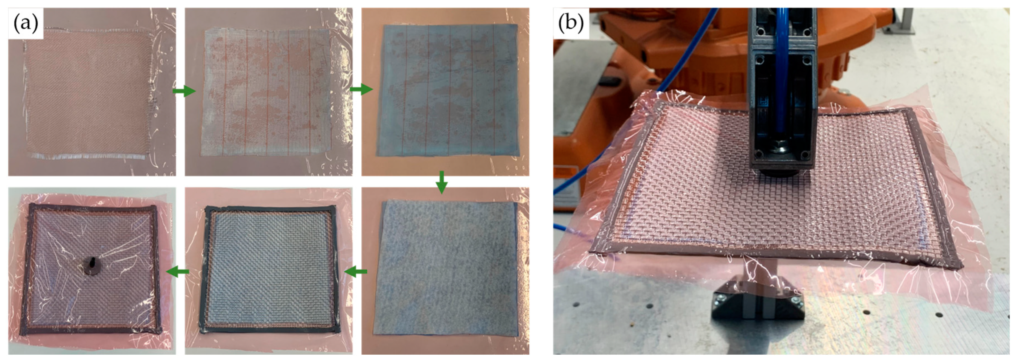
2.1. Forming Strategy

Instead of molds and manual draping efforts, the forming of various semi-finished products containing woven reinforcement fibers shall be realized by just two standard tools, such as hemispherical punches. To maintain the deformation and support the flexible fabric, metal wire mesh is added on any or both sides of the material and connected to it via a later soluble adhesive, auxiliary seams, or by enclosing the layup in a stretchable vacuum bag. The envisioned setup, depicted in Figure 1a, is comparable to double-sided incremental forming, with one forming tool on each side of the workpiece and each tool guided by an industrial robot. However, instead of clamping it on the edges, only a single point fixation amidst the layup is proposed to allow the drapability of the fibers and wires [25]. This fixation point must coincide with the starting point for the draping operations. Therefore, its location on the sheet as well as the initial orientation of the fabric with regard to the warp and weft yarns can be determined using a kinematic draping simulation with the objective to minimize the global amount of shear in the fabric [26].
All deformation shall be induced by the two forming tools, locally bending the fibers and wires and deforming them out of plane with respect to the fixation point [26]. Therefore, one of the tools acts as a support (passive tool), and the other, offset in the fiber/wire direction, actively bends the layup, as shown in Figure 1a. Due to the elasticity of the metal wires, they need to be deformed beyond the yield strength to retain the plastic deformation. The deflection necessary to achieve a permanent deformation is further increased by the intersecting wires resisting the bending, which must also be considered in robot path generation.
If a bending operation moves a point of the mesh closer toward another point, for example, because the latter has already been deformed, in-plane compressive stresses are introduced between them. In the desirable case, these lead to the in-plane deformation of shear. In the undesirable case, the compression leads to the out-of-plane deformation of wrinkling due to the low bending stiffness of woven reinforcement fabrics [26]. However, as metal wires are significantly better at transmitting compressive stresses than the sole FRP semi-finished product, and bending stiffness is substantially higher, as seen in Table 1, wrinkles rarely appear in metal wire meshes [28], and shear introduction into the reinforcement fabric should be promoted.
As shear adds up with increasing curvature, a correct sequence of forming operations is crucial. It should be chosen so that areas requiring the least shear, as determined by the draping simulation, are formed first. Two alternative strategies are possible [26], denoted as path forming and layering strategies, depicted in Figure 1b. In the former, full paths are formed one after another in order of ascending shear, each running in the fiber direction from an already formed starting point toward the edge of the fabric. In the latter, the mesh of already formed material grows a certain number of cells in each direction with respect to the fixation. Therefore, within each step, cells are formed in order of ascending shear. Practical experiments are conducted to determine the suitability of both strategies, as described in Section 2.3.

2.2. Materials

Process requirements and formability significantly depend upon the FRP semi-finished product that must be deformed. Four different general categories of materials seem feasible, with either glass, carbon, or other reinforcement fibers combined with different thermoset resins or thermoplastic matrix materials:
  • Dry reinforcement fiber fabric;
  • Thermoset prepregs;
  • Woven commingled thermoplastic and reinforcement fiber yarns;
  • Impregnated and consolidated thermoplastic organo sheets.
While dry reinforcement fiber fabrics (1) also require impregnation after forming, thermoset prepregs (2) only need to be cured as a subsequent process step. Commingling thermoplastic and reinforcement fibers is a common technique to facilitate thermoplastic impregnation by reducing the flow distance between the matrix material and reinforcement fibers while allowing good drapability [29]. Therefore, commingled yarn fabrics (3) require heating and pressure for impregnation and consolidation. In contrast to the first three categories, organo sheets (4) need to be heated above the glass transition or melting temperature of the thermoplastic to allow formability. Therefore, heat sources such as hot air guns, infrared heaters, contact heating, or using the wires as resistance heaters need to be incorporated in the forming setup.
If a vacuum bag realizes the bond between the FRP semi-finished product and metal wire mesh, the vacuum can be used for possible impregnation, consolidation, and curing steps after forming. These stages could further be supported by placing the layup in an autoclave. The wire mesh may only be removed after a rigid part of the desired shape is produced. To prevent imprints of the wires in the matrix material and to allow an easier separation, a peel ply, a stretchable smoothing sheet, and a nonwoven breather fabric could be placed between the mesh and the FRP, as shown in Figure 2. Alternatively, a hybrid material / fiber-metal-laminate could be produced if the metal wire mesh is permanently incorporated into the FRP.
In preliminary investigations not reported here, the deformation behavior of wire meshes with different wire diameters and mesh sizes was tested, and a plain weave of stainless steel 1.4301 wires with a diameter of 0.56 mm and a mesh size of 3.15 mm (Rolf Körner GmbH, Niederzier, Germany) was chosen to be best suitable for further experiments. The forming of dry reinforcement fiber fabric locally connected to a metal wire mesh with an adhesive was reported in [24]. Therefore, the experiments in the following focus on forming prepregs, commingled yarn fabrics, and organo sheets in vacuum setups, as shown in Figure 2. Materials used in the experiments are listed in Table 2.

2.3. Investigation of Wire Mesh Forming

To determine whether the path forming or layering strategy is better suitable for wire mesh forming, a 200 mm × 200 mm rectangle of the chosen mesh was centrally clamped to a pole and manually deformed into a hemispherical frustum of, ca., 120 mm in diameter and 40 mm in depth with two hand-guided hemispherical punches of 20 mm in diameter, as shown in Figure 3. Therefore, the path forming strategy and the layering strategy were each followed once, growing the formed area in each direction by about five cells in each step.
As described in Section 3 the layering strategy was more successful in forming the hemispherical frustum. Therefore, all subsequent experiments described in the following are conducted using the layering strategy.

2.4. Investigation of Prepreg Forming

The simultaneous forming of pre-impregnated glass fiber fabric and metal wire mesh was investigated in a vacuum bag setup. Therefore, 170 mm × 170 mm of the woven glass fiber fabric was placed on a bagging film and impregnated with Bisphenol A/F-based epoxy resin mixed with hardener using a brush. The layup further consisted of a nylon peel ply, a perforated separating foil, and a nonwoven absorbent fleece (see Table 2 for details). On top of the layup, 200 mm × 200 mm of metal wire mesh was placed, with the edges covered by two layers of 2 mm × 12 mm synthetic rubber vacuum sealing tape (DD Composite GmbH, Bad Liebenwerda, Germany) in order to seal the layup and prevent perforation of the foil by the wire ends. As shown in Figure 2, the vacuum bag was closed by a further layer of bagging film, with a vacuum connector placed in the middle of the mesh. The vacuum connector was also used to clamp the center of the layup to a pole. The bag was evacuated to a negative pressure of, ca., 0.850 bar before forming a doubly curved shape of, ca., 4 cm in height with two handheld forming tools following the layering strategy. Figure 4a shows the layup process and (b) the clamped and vacuumed layup before forming with the tools from Figure 3b. After forming, the part was cured under vacuum at room temperature for 48 h before finally being separated from the layup.

2.5. Investigation of Woven Commingled Yarn Forming

To investigate the basic feasibility of dieless forming and production of a thermoplastic FRP from commingled yarn fabric, glass/polypropylene commingled yarn weave was used as reinforcement material in a vacuum setup with peel ply, separating foil, breather fleece, and wire mesh, as shown in Figure 2. Again, the size of the fabric was 170 mm × 170 mm, and the wire mesh size was 200 mm × 200 mm. The edge of the mesh was embedded in one layer of high-temperature-resistant synthetic rubber vacuum sealing tape (R&G Faserverbundwerkstoffe GmbH, Waldenbuch, Germany) with an initial thickness of 3.2 mm and width of 12.7 mm. The layup was centrally clamped at the vacuum connector and evacuated to, ca., −0.850 bar, as shown in Figure 5a. Forming was again conducted using the manually guided hemispherical punches and following the layering strategy, producing a doubly curved shape of approximately 4 cm in height, as shown in Figure 5b. For impregnation and consolidation, the commingled yarn fabric was then heated to, ca., 180 °C for 15 min with an infrared heater placed 10 cm below the fixation point of the layup while maintaining the vacuum, as shown in Figure 5c. After cooling back to room temperature, the vacuum was turned off, and the produced thermoplastic FRP part was separated from the layup.

2.6. Investigation of Organo Sheet Forming

Simultaneous organo sheet and wire mesh forming was investigated using a 180 mm × 125 mm × 0.6 mm two-layered twill weave carbon fiber organo sheet with styrene-acrylonitrile matrix, a basis weight of 245 g/m², and 45% fiber volume content. As in the previous experiments, the FRP was placed on bagging film and covered with a peel ply, separating foil, and breather fleece, before a wire mesh of size 205 mm × 150 mm with the edges covered in high-temperature vacuum sealing tape was placed on top of the layup. The vacuum setup was closed with bagging film, clamped at the vacuum connector, and evacuated to, ca., −0.850 bar, as shown in Figure 6a. An infrared heater was placed 10 cm below the fixation point of the setup to heat the matrix of the organo sheet to approximately 190 °C, as depicted in Figure 6b. After reaching this temperature, the heater was removed, leaving the sheet deformable for, ca., 10 s. During this time, as many forming operations as possible were conducted with the handheld tools, following the layering strategy. To create a doubly curved shape of, ca., 4 cm in height, as shown in Figure 6c, sequential heating and forming were repeated until the whole sheet was deformed. Finally, the organo sheet was separated from the layup.

3. Results

Due to the elementary and manual nature of the experiments, the generated FRP parts are not evaluated for quantitative results, but qualitative conclusions from the experiments are presented in the following. These include an analysis of the formed part regarding the achieved shear and superficial, macroscopic part quality; an assessment of the overall feasibility of the different approaches; the effort necessary for each setup and forming operation; and essential factors for successful forming.

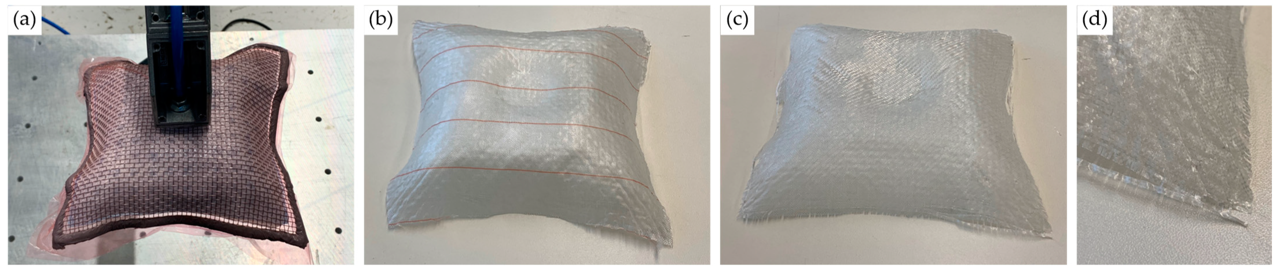
3.1. Wire Mesh Forming

As Figure 7 shows, both forming strategies allowed the introduction of sufficient shear into the wire mesh to form hemispherical frustums. However, the layering strategy in Figure 7b proved comparably simpler in use. As mentioned above, forming a complete path in the path forming strategy, especially toward the beginning of the process, requires higher forming forces since the—not yet deformed—intersecting wires must also be strongly deformed (see Figure 7a). The high degree of forming in one pass combined with a more asymmetric forming can also lead to undesired distortion in the remainder of the mesh. Therefore, the layering strategy produced a smoother and more precise hemispherical shape.

3.2. Prepreg Forming

Compared to pure wire mesh forming, prepreg forming in a vacuum bag proved more difficult. Due to the multiple additional layers of material, each bringing extra resistance against deformation, the necessary forming forces are higher, and the achievable shear is seemingly lower, as visible in Figure 8a. Furthermore, a more significant influence of local forming on the global shape of the layup was visible, as a certain reverse deformation of already formed areas occurred during forming. Components responsible for those effects must mainly be the bagging film and the separating foil, which, in contrast to the woven reinforcement fiber fabric, peel ply, and metal wires, behave isotropically and have tensile elongation as the primary deformation mechanism. Thereby, the elastic deformation component counteracts the shearing of the fibers.
However, as Figure 8a shows, the prepreg and wire mesh deformed together without detaching, and the shear of the wires was well transmitted to the reinforcement fibers. A cured FRP, which closely resembles the doubly curved shape of the whole clamped layup, could be produced and successfully removed from the adjacent layers of bagging film and peel ply, as seen in Figure 8b,c. A trough in the area of the vacuum connector and clamping, just like the imperfect symmetry of the part, suggests that hand-guided forming has limited accuracy.
Moreover, small wrinkles developed at the fabric edges, visible in Figure 8d, but coinciding with the wrinkling of the bagging film rather than developing due to surpassing the shear limit. Again, the wrinkling of the bagging film is due to a stretching of the foil in the bias (diagonal) direction while it is compressed in the perpendicular in-plane direction. The wrinkles in the FRP are of a similar order of magnitude as the imprints of the wire mesh, which are visible in the whole part (see Figure 8b–d).

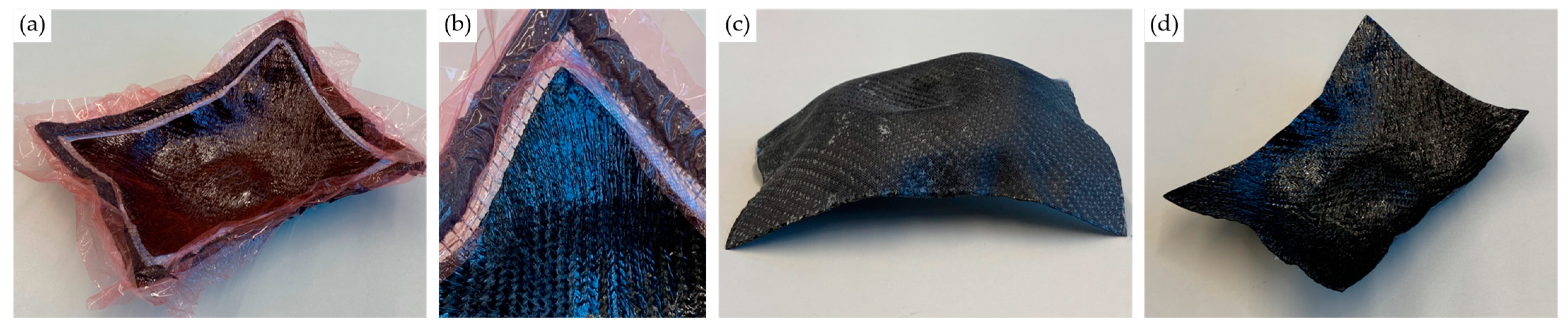
3.3. Woven Commingled Yarn Forming

During forming, glass fiber/polypropylene commingled yarn fabric behaved very similarly to the thermoset-impregnated glass fibers used in the previous experiment. The woven fabric was well drapable and deformed and sheared together with the wire mesh. Again, the layup containing bagging film and separating foil somewhat counteracted the deformation, and the amount of achievable shear seemed limited, resulting in a very similar doubly curved shape as in the previous experiment. This shape was maintained during the impregnation and solidification process, as the bagging film and all other used materials withstood the temperature applied. Thus, a solid part could finally be removed from the layup, as shown in Figure 9a,c. Again, wrinkles appeared at the corners (see Figure 9b) due to the wrinkling of the bagging film. This time, due to the higher thickness of the fabric, the outside of the geometry, which was in contact with the peel ply, did not show such wrinkles. Furthermore, no imprints of the wires were visible, possibly due to the higher basis weight and stiffness of the fabric.
However, as it is macroscopically visible in Figure 9b,c, impregnation was incomplete as white glass fibers were still apparent. The actual state of impregnation and consolidation was not investigated microscopically, as the part quality was not the focus of this study.

3.4. Organo Sheet Forming

Heating the organo sheet with the infrared heater allowed good dieless formability of the layup while not destroying the vacuum bagging film or other components. Due to the vacuum, the organo sheet and wire mesh deformed equally, and the shear of the wires transferred well to the FRP without losing contact, as recognizable in Figure 10a. After each heating and forming cycle, the solidification of the organo sheet due to its cooling aided in maintaining the shape of the just formed geometry. However, after re-heating, reverse deformation occurred during the forming of other parts of the geometry, similar to the previous experiments, so that some paths had to be repeatedly formed.
As shown in Figure 10c, the rigid organo sheet could successfully be removed from the layup, and its final doubly curved geometry is similar to the previous experiments. This includes the depression at the location of the vacuum connector as well as the asymmetry of the shape due to manual processing. The latter is intensified in comparison to the thermoset prepreg and commingled yarn weave, as the viscosity of the organo sheet’s matrix and thus the drapability of the woven fibers have not been entirely uniform in the whole sheet, due to inhomogeneous infrared heating of the already deformed sheet.
As in the part made of commingled yarn fabric, wrinkles at the edges, as seen in Figure 10b, occurred only on the inside of the geometry due to its direct contact with the bagging film. Imprints of the wires are not visible.

4. Discussion

Although the studies conducted were elementary in nature, with hand-guided tools and provisional setups, the experiments proved the general feasibility of using metal wire mesh as an auxiliary material for the dieless forming of woven reinforcement fiber semi-finished products such as prepregs, commingled yarn fabrics, and organo sheets. As assumed, realizing a temporary bond between the wire mesh and reinforcement material is crucial to not only support the flexible fabrics but directly transmit the deformation of the wire mesh to the fiber material. Therefore, the developed forming strategy, which involves introducing shear by bending and locally clamping the layup in a single, central fixation point, exploits the deformation characteristics of metal wire mesh, as listed in Table 1. To form doubly curved geometries, shearing the fibers is the most critical factor, which was supported by the metal wires’ bending stiffness and ability to transmit compressive forces during local dieless forming. In contrast, shear introduction by tensioning in the bias direction, as is typical in conventional fabric draping, would have involved clamping the edges of the layup. In this case, due to the boundary condition of a rigidly clamped area amidst the sheared region, the higher bending stiffness and the lower tensile strength of the wires compared to the fibers would have restricted the uniform shear introduction, as was seen by Wang et al. [28] in picture-frame and bias-extension tests.
The used vacuum layups showed great potential to realize the temporary bond between the wire mesh and reinforcement material. In contrast to the observations made without bonding the organo sheet and wire mesh in [27], the materials deformed well together, and no detachment was observed. Furthermore, in contrast to connecting the glass fiber fabric to a wire mesh with adhesive in [24], the vacuum could directly support the following processing steps. This included the curing of thermoset prepreg, impregnation, and consolidation of commingled yarn fabric as well as the reconsolidation of organo sheets, and also resin infusion after forming dry fabric could be realized with the layup.
Although the vacuum bagging film and the separating foil are highly stretchable with maximum elongations at break of 360% and 200%, respectively, their different deformation behavior compared to the woven materials led to some problems during forming. Their isotropic tensile stretching opposed the shear deformation of the weaves, increasing the necessary forming forces and the degree of deformation to compensate for the elastic strain component. The higher shear stiffness of the metal wire mesh compared to fiber fabrics and the organo sheet matrix could also have contributed to this. The local forming of a vacuumed stack had a more significant impact on the global shape of the layup in comparison to pure wire mesh forming, as reverse deformation of the already formed areas occurred during local bending operations and paths had to be repeatedly formed.
Moreover, wrinkles developed in the bagging film, impairing the surface quality of the FRP. Similarly, imprints of the metal wires were visible in the produced glass-fiber-reinforced thermoset, while the viscosity and stiffness of the thermoplastic FRPs prevented such an effect. Decreasing the vacuum, adding further layers of smoothing breather fleece, and experimenting with even more easily stretchable bagging and separating materials could prevent these effects and allow for a better surface and part quality.
Now that the general feasibility of the approaches is proven, efforts need to be made to develop and implement automated forming setups so that quantitative studies on materials, equipment setups, forming forces, part quality, and accuracy can be conducted. The conducted experiments highlight the importance of choosing the correct layup of materials and optimal system components, such as heaters to allow for the homogenous heating of organo sheets for formability. The heating system should furthermore go without the need for multiple reheating cycles causing high process times and possibly thermal stresses. Therefore, the possibility of using the metal wires as resistance heaters could be investigated. Furthermore, using localized heating in organo sheet forming, as examined in [24], could limit the effect of unwanted reverse deformation, by keeping the already deformed areas cold and rigid, albeit bearing the risk of retaining residual stresses in the material. For impregnation and consolidation of the formed commingled yarn fabrics, the vacuumed layup could be processed in an autoclave after forming.
The appropriate forming paths to produce the desired shapes with sufficient accuracy must be digitally generated to allow for automated processing. Therefore, the deformation behavior of the entire layup must be investigated experimentally, and a forming simulation should be set up to predict the elastoplastic behavior and determine the correct sequence and magnitude of forming operations. Therefore, the temperature dependency of the deformation of metal wire meshes and organo sheets should be considered.

5. Summary and Conclusions

As current forming processes for woven reinforcement fiber fabrics mainly involve expensive and complex molds, they are not cost-efficient for prototype and small batch production. Therefore, a dieless forming strategy was developed based on introducing shear into the fabric through local bending operations conducted using two standard tools, such as hemispherical punches. In order to maintain the shape of the flexible fibers during forming and to support the introduction of shear by in-plane compressive forces, it proved advantageous to form the metal wire mesh together with the woven fibers since they share the exact deformation mechanisms (shear and bending). Different layups of semi-finished reinforcement material, peel ply, separating foil, breather fleece, and wire mesh, enclosed in a stretchable vacuum bag, were tested and dielessly deformed in simple manual experiments. These proved that the approach is generally feasible and has great potential to enable automated and die-less forming of woven FRP, eliminating the need for expensive molds and greatly reducing manual efforts. As robot paths can be generated automatically, taking into account the developed forming strategy and the yet-to-be-set-up simulation, not only the cost but also the lead time of prototype and small series FRP production could be reduced. This can help enable the use of FRP for small- and medium-sized parts in more industries and companies. Furthermore, besides the considered FRPs, the approach could be used for the dieless forming of pure metal wire mesh or similar materials. To achieve these goals, further process and manufacturing cell development can build upon the insights into process and hardware requirements as well as the material behavior obtained in this study.

Author Contributions

Conceptualization, J.-E.R. and T.S.; methodology, J.-E.R.; validation, J.-E.R.; investigation, J.-E.R.; resources, T.S.; writing—original draft preparation, J.-E.R.; writing—review and editing, J.-E.R. and T.S.; visualization, J.-E.R.; supervision, T.S.; project administration, T.S.; funding acquisition, T.S. All authors have read and agreed to the published version of the manuscript.

Funding

This research was funded by the German Federal Ministry for Economic Affairs and Climate Action under the Program LuFo VI-1 iFish, grant number 20Q1917C.

Data Availability Statement

No new data were created or analyzed in this study. Data sharing is not applicable to this article.

Conflicts of Interest

The authors declare no conflict of interest. The funders had no role in the design of the study; in the collection, analyses, or interpretation of data; in the writing of the manuscript; or in the decision to publish the results.

References

  1. Flemming, M.; Ziegmann, G.; Roth, S. Faserverbundbauweisen: Fertigungsverfahren Mit Duroplastischer Matrix; Springer: Berlin/Heidelberg, Germany, 1996. [Google Scholar]
  2. Biron, M. Thermoplastics and Thermoplastic Composites: Technical Information for Plastics Users; Elsevier BH: Amsterdam, The Netherlands, 2006; ISBN 978-1-85617-478-7. [Google Scholar]
  3. Mallick, P. Fiber-Reinforced Composites: Materials, Manufacturing and Design; CRC Press: Boca Raton, FL, USA, 2008. [Google Scholar]
  4. Ehrenstein, G. Faserverbund-Kunststoffe; Hanser Verlag: Munich, Germany, 2006. [Google Scholar]
  5. Martin, I.; Del Saenz Castillo, D.; Fernandez, A.; Güemes, A. Advanced Thermoplastic Composite Manufacturing by In-Situ Consolidation: A Review. J. Compos. Sci. 2020, 4, 149. [Google Scholar] [CrossRef]
  6. Neitzel, M.; Mitschang, P.; Breuer, U. Handbuch Verbundwerkstoffe: Werkstoffe, Verarbeitung, Anwendung, 2nd ed.; Hanser: München, Germany, 2014; ISBN 9783446436978. [Google Scholar]
  7. Behrens, B.-A.; Raatz, A.; Hübner, S.; Bonk, C.; Bohne, F.; Bruns, C.; Micke-Camuz, M. Automated Stamp Forming of Continuous Fiber Reinforced Thermoplastics for Complex Shell Geometries. Procedia CIRP 2017, 66, 113–118. [Google Scholar] [CrossRef]
  8. Hennige, T. Flexible Formgebung von Blechen Durch Laserstrahlumformen; Meisenbach: Bamberg, Germany, 2001; ISBN 3875251407. [Google Scholar]
  9. Miller, A.K.; Gur, M.; Peled, A.; Payne, A.; Menzel, E. Die-Less Forming of Thermoplastic- Matrix, Continuous-Fiber Composites. J. Compos. Mater. 1990, 24, 346–381. [Google Scholar] [CrossRef]
  10. Elkington, M.P.; Sarkytbayev, A.; Ward, C. Automated composite draping: A review. In SAMPE 2017, Proceedings of the Washington State Convention Center, Seattle, WA, USA, 22–25 May 2017; SAMPE North America: Diamond Bar, CA, USA, 2017. [Google Scholar]
  11. Walczyk, D.F.; Hosford, J.F.; Papazian, J.M. Using Reconfigurable Tooling and Surface Heating for Incremental Forming of Composite Aircraft Parts. J. Manuf. Sci. Eng. 2003, 125, 333–343. [Google Scholar] [CrossRef]
  12. Ben Said, L. The incremental sheet forming; technology, modeling and formability: A brief review. Proc. Inst. Mech. Eng. E J. Process Mech. Eng. 2022, 236, 2729–2755. [Google Scholar] [CrossRef]
  13. Conte, R.; Ambrogio, G.; Pulice, D.; Gagliardi, F.; Filice, L. Incremental Sheet Forming of a Composite Made of Thermoplastic Matrix and Glass-Fiber Reinforcement. Procedia Eng. 2017, 207, 819–824. [Google Scholar] [CrossRef]
  14. Torres, S.; Ortega, R.; Acosta, P.; Calderón, E. Hot Incremental Forming of Biocomposites Developed from Linen Fibres and a Thermoplastic Matrix. SV-JME 2021, 67, 123–132. [Google Scholar] [CrossRef]
  15. Bagheri, S.; Kami, A.; Shakouri, M. Single point incremental forming of polyamide/30 wt% short glass fiber composite. J. Thermoplast. Compos. Mater. 2022, 36, 1938–1951. [Google Scholar] [CrossRef]
  16. Fiorotto, M.; Sorgente, M.; Lucchetta, G. Preliminary studies on single point incremental forming for composite materials. Int. J. Mater. Form. 2010, 3, 951–954. [Google Scholar] [CrossRef]
  17. Xiao, X.; Kim, J.-J.; Oh, S.-H.; Kim, Y.-S. Study on the incremental sheet forming of CFRP sheet. Compos.—A Appl. Sci. Manuf. 2021, 141, 106209. [Google Scholar] [CrossRef]
  18. Ambrogio, G.; Conte, R.; Gagliardi, F.; de Napoli, L.; Filice, L.; Russo, P. A new approach for forming polymeric composite structures. Compos. Struct. 2018, 204, 445–453. [Google Scholar] [CrossRef]
  19. Al-Obaidi, A.; Graf, A.; Kräusel, V.; Trautmann, M. Heat supported single point incremental forming of hybrid laminates for orthopedic applications. Procedia Manuf. 2019, 29, 21–27. [Google Scholar] [CrossRef]
  20. Al-Obaidi, A.; Kunke, A.; Kräusel, V. Hot single-point incremental forming of glass-fiber-reinforced polymer (PA6GF47) supported by hot air. J. Manuf. Process. 2019, 43, 17–25. [Google Scholar] [CrossRef]
  21. Emami, R.; Mirnia, M.J.; Elyasi, M.; Zolfaghari, A. An experimental investigation into single point incremental forming of glass fiber-reinforced polyamide sheet with different fiber orientations and volume fractions at elevated temperatures. J. Thermoplast. Compos. Mater. 2022, 36, 1893–1917. [Google Scholar] [CrossRef]
  22. Hou, C.; Su, X.; Peng, X.; Wu, X.; Yang, D. Thermal-Assisted Single Point Incremental Forming of Jute Fabric Reinforced Poly(lactic acid) Biocomposites. Fibers Polym. 2020, 21, 2373–2379. [Google Scholar] [CrossRef]
  23. Conte, R.; Serratore, G.; Ambrogio, G.; Gagliardi, F. Numerical analyses of long fiber–reinforced polymeric sheets processed by Single Point Incremental Forming. Int. J. Adv. Manuf. Technol. 2022, 123, 1203–1214. [Google Scholar] [CrossRef]
  24. Rath, J.-E.; Graupner, R.; Schüppstuhl, T. Processing Strategies for Dieless Forming of Fiber-Reinforced Plastic Composites. Machines 2023, 11, 365. [Google Scholar] [CrossRef]
  25. Rath, J.-E.; Graupner, R.; Schüppstuhl, T. Die-Less Forming of Fiber-Reinforced Plastic Composites. In Flexible Automation and Intelligent Manufacturing: The Human-Data-Technology Nexus; Kim, K.-Y., Monplaisir, L., Rickli, J., Eds.; Springer International Publishing: Cham, Switzerland, 2023; pp. 3–14. ISBN 978-3-031-18325-6. [Google Scholar] [CrossRef]
  26. Rath, J.-E.; Schwieger, L.-S.; Schüppstuhl, T. Robotic Die-Less Forming Strategy for Fiber-Reinforced Plastic Composites Production. Procedia CIRP 2022, 107, 1281–1286. [Google Scholar] [CrossRef]
  27. Rath, J.-E.; Schüppstuhl, T. Die-less forming of fiber-reinforced thermoplastic sheets and metal wire mesh. In Sheet Metal 2023, Proceedings of the 20th International Conference on Sheet Metal, Erlangen-Nürnberg, Germany, 2–5 April 2023; Merklein, M., Hagenah, H., Duflou, J.R., Fratini, L., Martins, P., Meschut, G., Micari, F., Eds.; Materials Research Forum LLC.: Millersville, PA, USA, 2023; pp. 37–44. [Google Scholar] [CrossRef]
  28. Wang, C.; Shankar, K.; Morozov, E.; Ram Ramakrishnan, K.; Fien, A. Characterization of Shear Behavior in Stainless Steel Wire Mesh Using Bias-Extension and Picture Frame Tests. J. Eng. Mech. 2020, 146, 04019127. [Google Scholar] [CrossRef]
  29. Alagirusamy, R.; Fangueiro, R.; Ogale, V.; Padaki, N. Hybrid Yarns and Textile Preforming for Thermoplastic Composites. Text. Prog. 2006, 38, 1–71. [Google Scholar] [CrossRef]
Figure 1. (a) Dieless forming principle with two tools deforming a wire mesh. (b) Path forming strategy and layering strategy forming sequences for producing a hemisphere [27].
Jmmp 07 00182 g001
Figure 2. Schematic layup with a vacuum bag enclosing wire mesh and reinforcement fabric.
Jmmp 07 00182 g002
Figure 3. (a) Centrally clamped metal wire mesh. (b) Hemispherical punch used as forming tool [27].
Jmmp 07 00182 g003
Figure 4. (a) Layup process starting with impregnated glass fiber fabric on bagging film, then adding peel ply, separating foil, breather fleece, wire mesh with vacuum tape on the edges, and bagging film with vacuum connector. (b) Clamped and vacuumed layup before forming.
Jmmp 07 00182 g004
Figure 5. (a) Clamped and vacuumed layup of commingled yarn fabric, peel ply, separating foil, breather fleece, and metal wire mesh enclosed in bagging film. (b) Dielessly formed doubly curved shape. (c) Heating the vacuumed and formed layup with an infrared heater for impregnation.
Jmmp 07 00182 g005
Figure 6. (a) Clamped and vacuumed layup of organo sheet, peel ply, separating foil, breather fleece, and metal wire mesh enclosed in bagging film. (b) Heating the vacuumed layup with an infrared heater to achieve formability. (c) Dielessly formed doubly curved shape.
Jmmp 07 00182 g006
Figure 7. (a) Process of dielessly forming a metal wire mesh according to the path forming strategy. (b) Process of dielessly forming a metal wire mesh according to the layering strategy [27].
Jmmp 07 00182 g007
Figure 8. (a) Dielessly formed doubly curved shape. (b) Glass-fiber-reinforced part with peel ply after curing and removal from the vacuum bag. (c) Cured glass-fiber-reinforced part. (d) Detailed view of a corner of the cured part with visible shear and wrinkles.
Jmmp 07 00182 g008
Figure 9. (a) Layup with commingled yarn fabric in a vacuum bag after impregnation and solidification. (b) Detailed view on a corner of the solidified part with visible shear and wrinkles. (c) Glass-fiber-reinforced part after removal from the vacuum bag (upper side) and (d) (lower side).
Jmmp 07 00182 g009
Figure 10. (a) Layup with organo sheet in vacuum bag after forming. (b) Detailed view on a corner of the part with visible shear and wrinkles. (c) Doubly curved carbon-fiber-reinforced part after removal from the vacuum bag (upper side) and (d) (lower side).
Jmmp 07 00182 g010
Table 1. Qualitative comparison of the deformation characteristics of woven fiber fabric vs. steel wire mesh.
Deformation CharacteristicWoven FabricSteel Wire Mesh
Bending stiffness- - -o
Shear stiffness- --
Tensile strength+ + ++
Compressive strength- - -o
Table 2. Materials used for the experiments.
MaterialWeave TypeBasis WeightThickness
Stainless steel 1.4301 wire mesh 1plain 3.15 × 0.56 mm
Glass fiber fabric 2twill160 g/m2
GF/PP commingled yarn fabric 3twill700 g/m2, 60 wt%
CF/SAN organo sheet 4twill245 g/m2, 45 vol%0.9 mm
Nylon peel ply 5plain85 g/m2
PP separating foil 5 25 µm
PE breather fleece 5nonwoven150 g/m21.6 mm
FEP bagging film 2 25 µm
1 Rolf Körner GmbH, Niederzier, Germany. 2 R&G Faserverbundwerkstoffe GmbH, Waldenbuch, Germany. 3 COMFIL ApS, Gjern, Denmark. 4 INEOS Styrolution Group GmbH, Frankfurt, Germany. 5 DD Composite GmbH, Bad Liebenwerda, Germany.
Disclaimer/Publisher’s Note: The statements, opinions and data contained in all publications are solely those of the individual author(s) and contributor(s) and not of MDPI and/or the editor(s). MDPI and/or the editor(s) disclaim responsibility for any injury to people or property resulting from any ideas, methods, instructions or products referred to in the content.

