Article

Study of the Law Motion of the Micro-EDM Drilling Process

by
Giuseppe Pellegrini
and
Chiara Ravasio
*
Department of Management, Information and Production Engineering, University of Bergamo, Viale Marconi 5, Dalmine, 24129 Bergamo, Italy
*
Author to whom correspondence should be addressed.
J. Manuf. Mater. Process. 2023, 7(5), 165; https://doi.org/10.3390/jmmp7050165
Submission received: 21 July 2023 / Revised: 31 August 2023 / Accepted: 4 September 2023 / Published: 8 September 2023
(This article belongs to the Special Issue Advances in Precision Machining Processes)

Abstract

:
Micro-EDM is an unconventional technology used to machine every type of electrically conductive material regardless of its mechanical properties. Material removal occurs through electrical discharges between the workpiece and the electrode immersed in a dielectric fluid. In drilling operations, the technology is able to realise microholes with excellent quality in terms of precision, quality surface, roundness, and taper to the detriment of the machining time, which is less than other technologies. Several efforts are being made to improve different features related to the process performance that are severely affected by both the operative conditions, such as the electrode material or the type of dielectric, and process parameters. The typical indexes used to characterise the performance are the machining time, the material removal rate, and the geometric indexes. These indexes are very effective and are easily measurable, but they do not give information about the evolution of the drilling process, which could be irregular due to the different phenomena occurring during machining. The aim of this paper is the development of a method able to elaborate the motion law of the electrode during the micro-EDM drilling operation. In order to do this, a single hole was manufactured in several steps, recording both the machining time and electrode wear for each step. In this way, the actual position of the electrode during the drilling can be measured without the use of a predictive model for electrode wear. It was tested to confirm that the multistep procedure did not introduce new phenomena, in contrast to the traditional drilling operation. This method was used to study the effects of the electrode diameter, the type of electrode, the length of the electrode out of the spindle, and the entity of the run-out on the process performance. The tests were executed on titanium alloy sheets using a tungsten carbide electrode and hydrocarbon oil as the dielectric. It was found that the descent of the electrode into the workpiece was not regular, but it depended on the level of debris concentration in the machining zone. The debris concentration was influenced by the type and diameter of the electrode, its length out of the spindle, and, to a lesser extent, the run-out. This method was found to be a useful method for an in-depth analysis of the micro-EDM drilling process, contributing to a better understanding of the physical aspects of the process.

1. Introduction

In electrical discharge machining (EDM), material removal is achieved through a plasma channel (a spark) between the workpiece and an electrode. Because of its non-mechanical nature, such a process is insensitive to material strength and can successfully operate on materials considered difficult to cut with conventional technologies. Generally, a dielectric medium is used to perform three main tasks. Firstly, it increases the insulation strength, allowing for shorter distances before a spark is activated; secondly, it helps remove the heat generated by the spark; lastly, it flushes the spark area, moving away any kind of polluted material (mainly debris) from both tools and the workpiece [1]. As a result, the dielectric fluid is locally (although temporarily) contaminated by the debris; in some cases, the amount of contamination plays a main role in controlling the removal process [2].
In recent years, the need to manufacture components of very small dimensions has resulted in remarkable growth in microtechnologies, i.e., technologies able to carry out the processing of particulars with dimensions ranging from hundredths to a few millimetres [3]. By controlling the process parameters, EDM may be also used to manufacture small-sized features (less than 1 mm) provided that the spark length is limited enough to achieve suitable process accuracy. In this case, the term micro-EDM is often used [4].
A relevant application of EDM technology in the micro-field is micro-EDM drilling (sometimes named microelectrical discharge drilling (EDD)), involving the machining of small diameter holes, less than 1 mm, sometimes with a very high aspect ratio (the ratio between the hole depth and the hole diameter) [5,6]. Several applications in the automotive, aerospace, biomedical, and electronic industries can be found [7]. During the process, the material is removed from both the workpiece and the electrode. The level of electrode wear can be a critical factor [5]; in fact, it represents the consumption of the tool to machine the micro-hole and, of course, its value affects the sustainability of the machining method.
The quality of a micro-EDM drilling operation is assessed by several indexes. The total machining time is easily measured and provides information about the efficiency of the process. Tool wear, evaluated by measuring the change in the length of the electrode (so, to be precise, axial wear is considered), also yields useful information. The material removal rate (MRR) (the volume of the removed material in the unit length of time) and the tool wear ratio (TWR) (estimated by the ratio between the volume of the material removed from the tool and that removed from the workpiece) are very common performance indexes. Geometrical features of the hole are also used to assess the quality of the part; in particular, the entry and exit diameters of the holes are measured. From this information, radial overcut and taper can be evaluated. In some cases, hole roughness has also been measured [8].
Both EDM and micro-EDM processes are affected by several process parameters, including electrical parameters, non-electrical parameters, and material properties [9]. Electrical process parameters are widely investigated. The type of electrode used [10], the type of dielectric [11], and the workpiece material are some of the most important non-electrical parameters. Different electrodes can be used [12], which are classified as a function of the material and the diameter. In general, microelectrodes are composed of tungsten carbide, brass, or copper. Tungsten carbide electrodes allow for more accurate machining, but this is at the expense of higher machining time. Copper and brass electrodes perform better but are subjected to a higher level of wear; moreover, the electrodes can be cylindrical and tubular. In cylindrical electrodes, the flow of the dielectric occurs through an external nozzle directed at the machining zone, while in tubular types, the dielectric flow occurs through the internal cavity of the electrode. In general, tubular electrodes are used for generating high hole depth. The properties of the workpiece material can influence its machining, especially its density, thermal conductivity, and electrical resistivity [13].
Many researchers have studied the optimisation of the electrical process parameters in the cases of die-sinking EDM and wire EDM. Using algorithms to find the best conditions is a common strategy. For example, in [14], an ACO (ant colony optimisation) algorithm (a probabilistic technique) was used to optimise MRR and SR (surface roughness); the solution converged after 50 iterations. Another approach was used in [15], where a GA (genetic algorithm) was applied to optimise the process. An ABC (artificial bee colony) algorithm was found to perform better than the above-mentioned methods [16]. An evolutionary strategy (ES) algorithm was also used in [17]. Different types of strategy optimisation were compared in [18] in the case of PMEDM (powder-mixed EDM) assisted by a magnetic field.
By contrast, there are far fewer papers related to micro-EDM [19]. In the case of micromachining, there are more difficulties in terms of power control, electrode wear, real-time processing monitoring, debris management, and other aspects [20]. In [21], the authors studied the effects of pulse on time, discharge voltage, capacitance, and electrode rotation speed on the material removal rate, the side gap width, and the taper ratio. The cooling holes of turbine blades were taken into account in [22], which involved a multiobjective optimisation of process parameters on Inconel 718. Micro-EDM drilling of a titanium superalloy was investigated in [23], and it was found that machining performance is mostly affected by the peak current and pulse on time.
As in most drilling operations, the effectiveness of the process is linked to the ability to evacuate the removed material (in this case, in the form of debris) from the hole bottom. It has been reported that dielectric contamination increases with the hole depth, affecting the MRR [24]. A strategy used to improve the flow of the dielectric, and consequently debris removal, is using a D-shaped solid electrode in the machining process [25]. Single-and dual-notch cross-sectional microtools were tested in micro-EDM drilling, and it was found that the single-notch type improves the debris removal rate [26]. Another approach used in [27] consists of the planetary movement of the electrode through ultrasonic vibrations. It was possible to realise microholes with a very high aspect ratio. The ultrasonic-vibration-assisted EDM was also used in [28,29], which led to an increase of two to four times in the MRR. The TWR and the taper of microholes were reduced by about 50% and 24%, respectively. In [30], the electrode was subjected to ultrasonic longitudinal and torsional vibrations using a transducer. In this way, the MRR increased by nearly two times, and electrode wear and the taper of the hole were reduced owing to better debris removal efficiency.
A performance evaluation using the final values of these indexes does not give information about the evolution of the drilling operation. In fact, these indexes can be considered SMART (Specific, Measurable, Achievable, Realistic, and Timely), but they do not allow for an in-depth understanding of what occurs during the process. The evolution of the drilling operation is not regular due to the occurrence of many phenomena during the machining process, for example, changes in the amount of debris present in the machining zone. In the beginning, the dielectric in the machining zone is very clean, while during the penetration of the electrode into the workpiece, this amount increases due to an increase in the difficulty of removing debris from the machining zone, considering the very short gap between the electrode and the workpiece (several microns or tens of microns). Another aspect that changes during the drilling operation is related to the electrode. It is subjected not only to frontal wear but also to radial wear, causing changes in the shape of the electrode tip.
To monitor the evolution of the drilling operation, a method for measuring the law motion of the electrode is necessary. Some authors investigated the electrode movement along the machine’s Z axis. In all cases, a direct measurement of the spindle Z position was performed [26]. The authors of [31] used a laser device. In this technique, however, the actual position of the electrode tip is unknown because it depends on tool wear as well. The actual position can be estimated by using a predictive model of electrode wear [26].
The aim of this work is to develop a method able to monitor the evolution of the drilling operation. A single hole was manufactured in several steps while recording the machining time and electrode wear for each step. By measuring the extent of electrode wear at the end of each drilling step, the evolution of the current depth of the hole can be easily analysed. This method was used to study the effects of some aspects related to the electrode (diameter, type, length of the electrode out of the spindle, and run-out) on the process performance. This technique was found to be a useful method for an in-depth analysis of the micro-EDM drilling process, contributing to a better understanding of the phenomena occurring during the machining process.

2. Experimental Method

Drilling was performed in multiple steps in order to obtain the motion law of the electrode (Figure 1). The process involved multiple descent strokes of the electrode with the same step length until reaching the planned hole depth in the Z axis of the machine. At the end of each step, the electrode was taken out of the machining hole, and electrode wear was measured at a reference point. After this, the electrode was fitted into the hole and descended up to the previous Z value, and a new step was carried out. The drilling process continued by alternately repeating steps 3 and 4 of Figure 1 until the electrode reached its final value of the programmed stroke. Machining time and frontal electrode wear of each step were recorded. This machining procedure was completely automatised. Electrode wear for step i was measured by the difference between the starting length of the electrode before step i and the final length of the electrode after the machining of step i.
It is worth noting that the recorded time for each step was the actual time of erosion, that is, the amounts of time necessary to position the tool into the hole and measure the wear were excluded.
The depth of the hole at the end of the i step (ZR,i) can be easily calculated using Equation (1):
Z R , i = Z P , i + n = 1 i w n
where ZP,i is the planned Z stroke for step i, and wn is the frontal electrode wear of a single step. Z assumes negative values, while wn is positive (Figure 2).
This procedure can change some aspects compared with the traditional drilling operation. The effects of the multistep procedure were investigated on a titanium sheet (Ti6Al4V) of thickness 1 mm using a Sarix SX-200 machine. For the tests, tungsten carbide electrodes and hydrocarbon oil as dielectric were used. The finishing process parameters were selected as reported in Table 1. Current, gap, gain, energy, and regulation do not have a unit of measurement, and thus they are indexes proportional to the actual value. Gain is a parameter that controls the gain of the reaction block. The gap parameter is a value proportional to the distance between the electrode and the workpiece during the erosion, and its real value can be estimated by measuring the overcut. The energy parameter establishes the shape of the pulse. Finally, regulation indicates a certain regulation management algorithm defined by the machine manufacturer.
The method was tested using different lengths of the drilling step, 0.4–0.2–0.1 mm; the traditional drilling was denoted as “no step”. Each condition was tested three times.
After the definition and validation of the procedure to measure the motion law of the electrode during the drilling operation, some tests were conducted to study the effects of some operative conditions, namely the type of electrode (cylinder or tubular), the diameter, the length of the electrode out of the spindle (Figure 3), and the amplitude of the run-out of the electrode.
Table 2 outlines the fixed parameters and conditions, while Table 3 provides the variable parameters. Each experimental condition was tested thrice in order to evaluate the reproducibility.

3. Analysis of the Results

3.1. Validation of the Multistep Procedure

Before studying the effects of some operative conditions on the process performance, it was necessary to verify the effects of the multistep procedure on some aspects compared with the traditional drilling operation. Figure 4, Figure 5 and Figure 6 show comparisons of the machining time, electrode wear, and the diameters of the holes obtained using different step lengths during the drilling operation. It can be seen that, with an increase in the number of steps, in other words, a decrease in the length of each step, the machining time also increased (with the maximum number of steps, the machining time increased by around 10% compared with traditional drilling). The multistep drilling procedure did not have any effect on electrode wear or the diameter of the hole.
In conclusion, slight changes were observed in all output parameters. In the less favourable parameter, i.e., the machining time, the differences consistently increased with the step numbers, supporting the hypothesis that no new phenomenon occurred. From these results, it is possible to assert that this procedure does not affect the significance of the results.
Nevertheless, the modest effect of the multistep drilling procedure on the performance does not hold true in every condition. In fact, in the case of PMEDM (powder-mixed EDM), the process performance is severely influenced by the drilling operation method, such as traditional drilling or multistep drilling. The process in this case is affected by the characteristics of the dielectric in the machining zone (the concentration of the powder and the dimension of the particles).
An example of the law motion curves obtained after data analysis is shown in Figure 7, where the three tested step lengths are reported. The trend is typical for cylinder electrodes (without the internal dielectric flushing). It is possible to subdivide the curves into the following four regions:
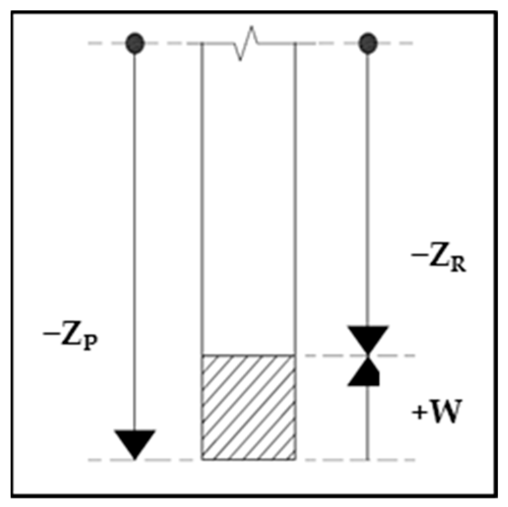
  • Initial phase: The electrode undergoes the first stages of erosion of the material, with an almost regular trend of the law of motion.
  • Acceleration phase: The process accelerates, probably due to both an increase in the amount of debris in the machining zone and the shape of the tool’s tip, which stabilises after the initial wear.
  • Deceleration phase: The machining process decelerates, and the concavity of the curve changes. This deceleration can be attributed to the worsening of the washing conditions using the dielectric with an increase in the depth and an excessive amount of debris in the machining zone.
  • Perforation phase: When the electrode erodes, the entire thickness of the plate and the machining time of the steps rapidly decrease because the electrode only performs a finishing action on the sides of the hole. The velocity rapidly increases.
These regions, in particular the second and the third ones, are very interesting and allow for an in-depth understanding of the process. In fact, if considering only the final machining time, the different regions cannot be revealed.
Debris control in the micro-EDM drilling process plays a critical role. It is reasonable to assume that the flushing effect is worsened with an increase in hole depth, thus affecting the amount of debris. A machining area with an excessive amount of debris can impair the machining process in terms of the MRR due to the occurrence of many short circuits negatively affecting the process. On the other hand, a very clean dielectric causes a delay in the generation of the electric discharge, also impairing the process. It is therefore possible to assume that there is an optimal amount of debris, corresponding to the maximum Z velocity of the electrode. Before reaching this amount, the debris amount increases in the dielectric, and the machining accelerates. After reaching the optimal amount, the dielectric has excess debris, which destabilises the machine, and the process decelerates. The time to reach the optimal debris amount depends on the operative conditions such as the type or the length of the electrode. Nevertheless, the optimal amount of debris cannot be obtained in all conditions; in this case, the curves do not show the deceleration phase.
The reproducibility in general was very good. In Figure 8, the three curves obtained through the repetition of the same experimental conditions are reported. The trend is always the same with a good overlapping.

3.2. Analysis of the Case Studies

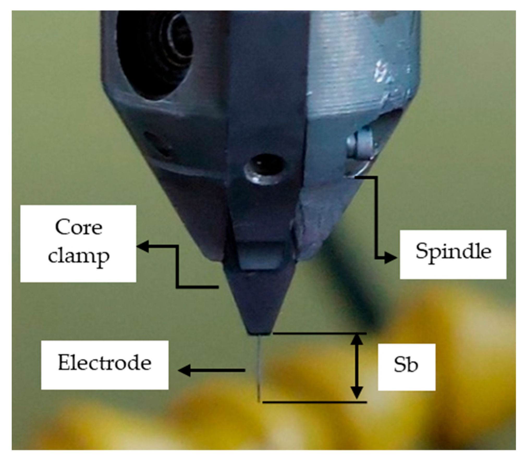
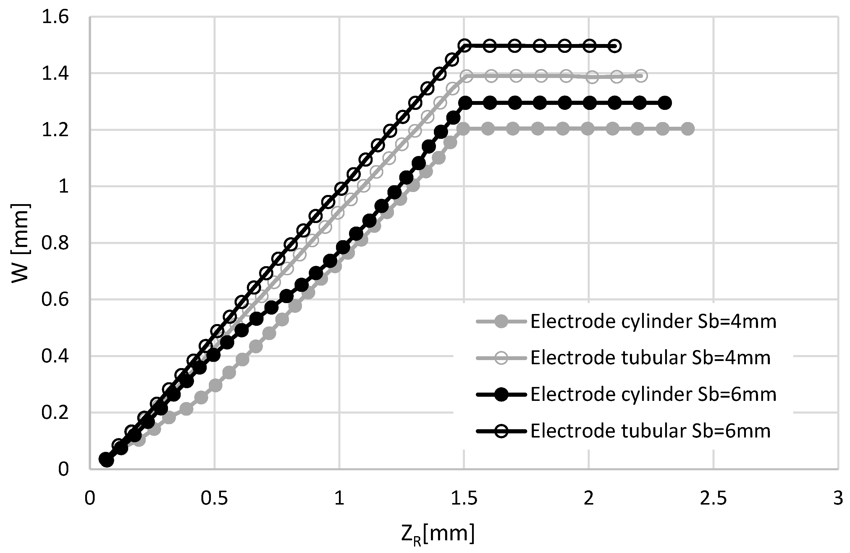
3.2.1. Effects of the Type, Diameter, and Length of the Electrode

The type of electrode severely affects the law motion of the electrode along the Z axis (Figure 9). The behaviour of cylinder and tubular electrodes is very different. Tubular electrode curves have an almost constant slope, while the cylinder ones show different phases: In the first part, the drilling process is very fast, and then the descent is slowed down. This different behaviour is due to the different levels of debris contamination of the dielectric in the machining zone. By using the tubular electrode, internal washing guarantees almost the same level of dielectric cleaning, thus allowing for a regular feed rate of the electrode. Nevertheless, tubular electrodes also display slight nonlinearity since their slopes increase with depth. This behaviour can be explained by the assumption that the amount of debris is less than the optimal amount when using tubular electrodes; therefore, a small increase in the amount of debris improves the feed rate.
The cylinder electrode performs very well in the first step of hole drilling, but in later steps, the external flushing of the dielectric is not effective enough, and the optimal amount of debris is exceeded; therefore, the electrode descent is slowed down.
It is worth noting that, in some cases (e.g., grey curves in Figure 9), the total machining times of cylindrical and tubular electrodes are similar to each other. In such conditions, machining times would not highlight any different behaviour. In fact, if some experimental conditions were changed, machining times would significantly differ; in this case, larger differences in the total machining time could be obtained by changing either the final depth or the electrode diameter.
Two levels of electrode lengths were compared (4 and 6 mm). The length of the electrode seems to have different effects in the two electrode types, but when analysing the curves considering the optimal amount of debris, the same results can be obtained. In general, when a high length of the electrode is used, more time is necessary to reach the optimal amount of debris because washing works better than the case in which a low length of the electrode is used. Therefore, in the case of cylinder electrodes, the acceleration phase has a higher time length when the electrode length is high. The same effect is present for the tubular electrodes, i.e., using a high electrode length causes the descent of the electrode to move slowly due to the very effective washing of the machining zone.
In Figure 10, wear curves are reported. The curves are very regular. Tubular electrodes have more wear than cylinder ones, with around 20% wear, probably due to the higher machining time. The effect of the electrode length on the electrode wear is modest.
Information about wear is required for evaluating the real depth ZR, but wear progression over time itself does not add significant information. The wear trends display little shift from linear behaviour (if any at all); therefore, wear can be fully described by its final value.
The effect of the electrode diameter on the feed rate of the electrode is reported in Figure 11. The behaviour of the tubular electrode is analysed. The feed rate worsens as the electrode diameter increases due to the higher amount of material volume to remove. When taking into account the material removal rate (MRR), however, the larger diameter performs better.
It is interesting to note that the electrode length has an effect only when the electrode diameter is 0.15 mm. Electrodes with larger diameters are less sensitive to small variations in the electrode length, which influences the local run-out. This is possibly due to the machining time, which severely affects the shape of the electrode tip. However, further investigations are necessary to explain this behaviour.
The length of the electrode out of the spindle also affects the feed rate of the electrode. Figure 12 shows the three typical curves obtained using a cylinder electrode with three different electrode lengths. A low value of electrode length results in better performance in the initial depth but the optimal amount of debris is reached earlier. As the electrode length increases, the debris amount increases more gradually, and more time is needed for the start of the deceleration phase.
The electrode length has the same effect when a smaller electrode is used (Figure 13). The transition point between the acceleration and deceleration phases is reached later when larger electrode lengths are used. It can be noted, that in this case, the extent of the acceleration phase is longer than with a larger electrode (see Figure 12). This can be justified by considering the area effect [32]. The amount of debris generated is a square function of the electrode diameter, whereas debris removal is only linearly dependent on the diameter. Therefore, larger electrodes contaminate the dielectric fluid more, thus reaching the optimal concentration of debris earlier, which represents the transition point.

3.2.2. Effect of the Run-Out

The effects of the run-out electrodes are reported in Figure 14 and Figure 15. In general, the electrode is rotated during the machining process. It is attached to a spindle subjected to a tool setting error that is the cause of run-out. In microdrilling applications, run-out can decrease the accuracy of the machined hole, causing a larger diameter. To compensate for this effect in deep drilling, a guide is used to keep the electrode during its descent. The law motion of the electrode can be affected by the run-out parameter.
The trends observed in the curves with high and low run-out do not show appreciable differences between each other. It can be noted that, when taking into account only the final time, some degree of difference can be observed. In fact, in both cases, a high run-out rate apparently leads to better performance than a low run-out rate.
Nevertheless, it is interesting to note that the first step of the descent of the electrode is not affected by run-out. The run-out parameter only affects the process after a certain depth is reached, where a low run-out rate causes debris removal from the machining zone to become more difficult, thus causing a slowdown of the drilling process. This is especially evident in Figure 15, which indicates that, with low run-out, the machining time of the last step before perforation is very high.

3.2.3. Effect of the Drilling Depth

Keeping the experimental conditions fixed, the effect of the hole depth was also investigated. The curves perfectly overlap for both electrode diameters (Figure 16 and Figure 17). This observation might be obvious: The descent of the electrode is not affected by the amount of material that has to be removed before perforation. Nevertheless, the study of the law of motion is confirmed to be a valid method to study the evolution of the process. The multistep drilling procedure does not affect the evolution of the drilling process.

4. Conclusions

In micro-EDM drilling, the optimisation of process parameters does not resolve all the critical aspects of the machining process. Understanding the material removal process may support this task. In fact, the final data obtained regarding the overall performance of the process could lead to overlooking the occurrence of some phenomena during the machining process. Only through the study of the evolution of the process can some critical issues be highlighted and, consequently, some solutions be proposed.
In this paper, a method to study the evolution of the micro-EDM drilling process was proposed, namely multistep drilling. First, the method was found to be an effective tool for the elaboration of the motion law of the electrode inside the workpiece. In fact, using the experimental data, it was possible to confirm that this method does not significantly affect the drilling operation in terms of the machining time, electrode wear, and geometrical characteristics of the hole.
This method proved to be a very effective approach for highlighting the influence of some operative conditions on the drilling process. Debris control and therefore the amount of debris in the machining zone play a very important role. In general, both parameters depend on the operative conditions in terms of the type and diameter of the electrode, and the electrode length; run-out is less important. The presence of debris facilitates the machining process until the optimal amount of debris is reached; then, the machining process decelerates due to a large number of short circuits. Within the limitations of the tested experimental conditions, run-out does not affect the process. The multistep drilling method was found to be an effective tool to increase our understanding of this process. This method allows for a better understanding of what occurs during the drilling of a microhole and could be used in the optimisation phase to select the best operative conditions to use in some industrial applications. Moreover, through the analysis of the law motion, critical aspects can be identified, and some improvements can be made to achieve better performance and therefore a greater level of sustainability.

Author Contributions

Conceptualisation, project administration, investigation, data curation, writing—original draft preparation, G.P. and C.R. All authors have read and agreed to the published version of the manuscript.

Funding

This research received no external funding.

Data Availability Statement

The data presented in this study are available upon request from the corresponding author.

Conflicts of Interest

The authors declare no conflict of interest.

References

  1. Li, G.; Natsu, W. Realization of micro EDM drilling with high machining speed and accuracy by using mist deionized water jet. Precis. Eng. 2020, 61, 136–146. [Google Scholar] [CrossRef]
  2. Sivaprasad, P.V.; Panneerselvam, K.; Noorul Haq, A. A comparative assessment in sequential μ drilling of Hastelloy X using laser in combination with μEDM and μECM. J. Braz. Soc. Mech. Sci. Eng. 2021, 43, 354. [Google Scholar] [CrossRef]
  3. Podaný, J.; Tomicek, J. Analysis of small holes manufacturing for optomechanical components. Manuf. Technol. 2020, 20, 229–236. [Google Scholar] [CrossRef]
  4. Pham, D.T.; Dimov, S.S.; Bigot, S.; Ivanov, A.; Popov, K. Micro-EDM—Recent developments and research issues. J. Mater. Process. Technol. 2004, 149, 50–57. [Google Scholar] [CrossRef]
  5. Pham, D.T.; Ivanov, A.; Bigot, S.; Popov, K.; Dimov, S. A study of micro-electro discharge machining electrode wear. Proc. Inst. Mech. Eng. Part C J. Mech. Eng. Sci. 2007, 221, 605–612. [Google Scholar] [CrossRef]
  6. Kibria, G.; Jahan, M.P.; Bhattacharyya, B. Micro-Electrical Discharge Machining Processes Technologies and Applications; Springer Nature: Berlin/Heidelberg, Germany, 2019; ISBN 978-981-13-3073-5. [Google Scholar]
  7. Das, A.; Ambastha, S.; Priyadarshni, N.; Samanta, S. Fabrication of hydrophobic surfaces on Titanium using Micro-EDM ex-hibiting antibacterial properties. Proc. Inst. Mech. Eng. Part B J. Eng. Manuf. 2022, 236, 1093–1101. [Google Scholar] [CrossRef]
  8. Liu, Q.; Yang, F.; Sun, S.; Yang, M.; Shao, J. Surface Integrity of Micro EDM Surface Using Electrodes of Various Diameters. Coatings 2019, 9, 805. [Google Scholar] [CrossRef]
  9. Singh, V.; Sharma, A.K.; Goyal, A.; Saxena, K.K.; Negi, P.; Rao, P.C.S. Electric discharge machining performance measures and optimisation: A review. Adv. Mater. Process. Technol. 2023, 1–14. [Google Scholar] [CrossRef]
  10. Yilmaz, O.M.; Okka, A. Effect of single and multi-channel electrodes application on EDM fast hole drilling performance. Int. J. Adv. Manuf. Technol. 2010, 51, 185–194. [Google Scholar] [CrossRef]
  11. Niamat, M.; Sarfraz, S.; Aziz, H.; Jahanzaib, M.; Shebab, E.; Ahmad, W.; Hussain, S. Effect of different dielectrics on material removal rate, electrode wear rate and microstructure in EDM. Procedia CIRP 2017, 60, 2–7. [Google Scholar] [CrossRef]
  12. Ho, K.H.; Newman, S.T. State of the art electrical discharge machining (EDM). Int. J. Mach. Tools Manuf. 2003, 431, 287–300. [Google Scholar] [CrossRef]
  13. Khan, A.A.; Al Hazza, M.H.F. Performance of electrical discharge machining (EDM) with nickel added dielectric fluid. IIUM Eng. J. 2018, 19, 215–222. [Google Scholar] [CrossRef]
  14. Mondal, N.; Nishant; Mandal, M.C.; Das, S.; Banerjee, T. Comparative study on EDM process parameters optimization using BBO and ACO algorithms. Mater. Today Proc. 2022, 62, 6601–6605. [Google Scholar] [CrossRef]
  15. Tzeng, C.-J.; Chen, R.-Y. Optimization of Electric Discharge Machining Process Using the Response Surface Methodology and Genetic Algorithm Approach. Int. J. Precis. Eng. Manuf. 2013, 14, 709–717. [Google Scholar] [CrossRef]
  16. Mukherjee, R.; Chakraborty, S. Selection of EDM Process Parameters Using Biogeography-Based Optimization Algorithm. Mater. Manuf. Process. 2012, 27, 954–962. [Google Scholar] [CrossRef]
  17. Jafarian, F. Electro discharge machining of Inconel 718 alloy and process optimization. Mater. Manuf. Process. 2020, 35, 95–103. [Google Scholar] [CrossRef]
  18. Rouniyar, A.K.; Shandilya, P. Optimization of process parameters in magnetic field assisted powder mixed EDM of aluminium 6061 alloy. Proc. Inst. Mech. Eng. Part C J. Mech. Eng. Sci. 2021, 235, 2998–3014. [Google Scholar] [CrossRef]
  19. Chen, Y.; Hu, S.; Li, A.; Cao, Y.; Zhao, Y.; Ming, W. Parameters Optimization of Electrical Discharge Machining Process Using Swarm Intelligence: A Review. Metals 2023, 13, 839. [Google Scholar] [CrossRef]
  20. Wong, Y.S.; Rahman, M.; Lim, H.S.; Han, H.; Ravi, N. Investigation of micro-EDM material removal characteristics using single RC-pulse discharges. J. Mater. Process. Technol. 2003, 140, 303–307. [Google Scholar] [CrossRef]
  21. Sapkal, S.U.; Jagtap, P.S. Optimization of Micro EDM Drilling Process Parameters for Titanium Alloy by Rotating Electrode. Procedia Manuf. 2018, 20, 119–126. [Google Scholar] [CrossRef]
  22. Dilip, D.G.; Panda, S.; Mathew, J. Characterization and Parametric Optimization of Micro-hole Surfaces in Micro-EDM Drilling on Inconel 718 Superalloy Using Genetic Algorithm. Arab. J. Sci. Eng. 2020, 45, 5057–5074. [Google Scholar] [CrossRef]
  23. Pradhan, B.B.; Masanta, M.; Sarkar, B.R.; Bhattacharyya, B. Investigation of electro-discharge micro-machining of titanium su per alloy. Int. J. Adv. Manuf. Technol. 2009, 41, 1094–1106. [Google Scholar] [CrossRef]
  24. Boban, J.; Ahmed, A.; Assam, A. Effect of recirculation zone on debris evacuation during EDM deep hole drilling. Procedia CIRP 2021, 102, 393–398. [Google Scholar] [CrossRef]
  25. Kim, D.; Kim, Y.S.; Song, K.Y.; Ahn, S.H.; Chu, C.N. Kerosene Supply Effect on Performance of Aluminum Nitride Micro-Electrical Discharge Machining. Int. J. Precis. Eng. Manuf. 2022, 23, 581–591. [Google Scholar] [CrossRef]
  26. Huang, T.-W.; Sheu, D.-Y. High aspect ratio of micro hole drilling by Micro-EDM with different cross-section shape micro tools for flushing process. Procedia CIRP 2020, 95, 550–553. [Google Scholar] [CrossRef]
  27. Yu, Z.Y.; Zhang, Y.; Li, J.; Luan, J.; Zhao, F.; Guo, D. High aspect ratio micro-hole drilling aided with ultrasonic vibration and planetary movement of electrode by micro-EDM. CIRP Ann. 2009, 58, 213–216. [Google Scholar] [CrossRef]
  28. Zhang, P.; Yin, Z.; Yu, D.; Shen, X.; Wang, Y.; Dai, C.; Zhang, K. Experimental research and multi-objective optimization of ultrasonic vibration–assisted EDM for Ti6Al4V micro-holes. Int. J. Adv. Manuf. Technol. 2023, 127, 3413–3425. [Google Scholar] [CrossRef]
  29. Zhang, P.; Yin, Z.; Dai, C.; Cao, Z.; Miao, Q.; Zhang, K. The effect of ultrasonic amplitude on the performance of ultrasonic vibration-assisted EDM micro-hole machining. Int. J. Adv. Manuf. Technol. 2022, 122, 1513–1524. [Google Scholar] [CrossRef]
  30. Yin, Z.; Zhang, P.; Zhou, P.; Zhang, K.; Sun, Q.; Zhan, Q.; Li, H. A novel EDM method using longitudinal-torsional ultrasonic vibration (LTV) electrodes to improve machining performance for micro-holes. J. Manuf. Process. 2023, 102, 31–243. [Google Scholar] [CrossRef]
  31. Li, G.; Natsu, W.; Yu, Z. Elucidation of gap area phenomenon in micro EDM drilling through direct observation. Procedia CIRP 2020, 95, 210–214. [Google Scholar] [CrossRef]
  32. Liu, Q.; Zhang, Q.; Zhu, G.; Wang, K.; Zhang, J.; Dong, C. Effect of Electrode Size on the Performances of Micro-EDM. Mater. Manuf. Process. 2016, 31, 391–396. [Google Scholar] [CrossRef]
Figure 1. The multiple steps of the drilling procedure.
Jmmp 07 00165 g001
Figure 2. Evaluation of the actual depth of the hole during the multistep drilling procedure.
Jmmp 07 00165 g002
Figure 3. Micro-EDM spindle and electrode.
Jmmp 07 00165 g003
Figure 4. Machining time using different step lengths; the electrode diameter is 0.1 mm.
Jmmp 07 00165 g004
Figure 5. Electrode wear using different step lengths; the electrode diameter is 0.1 mm.
Jmmp 07 00165 g005
Figure 6. The top and bottom diameters of the hole obtained using different step lengths; the electrode diameter is 0.1 mm.
Jmmp 07 00165 g006
Figure 7. Motion law of the cylinder electrode with varying the length of the step.
Jmmp 07 00165 g007
Figure 8. Example of the reproducibility of the tests.
Jmmp 07 00165 g008
Figure 9. The law motion with varying the type of electrode (cylinder and tubular) and electrode length (Sb), with an electrode diameter of 0.15 mm and a hole depth of 1.5 mm.
Jmmp 07 00165 g009
Figure 10. Electrode wear, varying the type of electrode (cylinder and tubular) and the electrode length (Sb), with an electrode diameter of 0.15 mm and a hole depth of 1.5 mm.
Jmmp 07 00165 g010
Figure 11. The law motion with varying the diameter of the tubular electrode and the electrode length (Sb); hole depth is 1.5 mm.
Jmmp 07 00165 g011
Figure 12. The law motion with varying the electrode length (Sb); hole depth is 1 mm, and the cylinder electrode’s diameter is 0.15 mm.
Jmmp 07 00165 g012
Figure 13. The law motion with varying the electrode length (Sb) for two hole depths, using a cylinder electrode with a diameter of 0.1 mm.
Jmmp 07 00165 g013
Figure 14. The law motion with varying the run-out value of the electrode, with a hole depth of 1 mm, using a cylinder electrode with a diameter of 0.1 mm and an electrode length of 3 mm.
Jmmp 07 00165 g014
Figure 15. The law motion with varying the run-out value of the electrode, with a hole depth of 0.5 mm, using a cylinder electrode with a diameter of 0.3 mm and an electrode length of 6 mm.
Jmmp 07 00165 g015
Figure 16. The law motion with varying the hole depth (Sp), using a cylinder electrode with an electrode diameter of 0.15 mm and electrode length of 4 mm.
Jmmp 07 00165 g016
Figure 17. The law motion with varying the hole depth (Sp), using a cylinder electrode with a diameter of 0.1 mm and an electrode length of 4 mm.
Jmmp 07 00165 g017
Table 1. Process parameters used during the experimental tests.
Process ParameterValue
Polarity-
Width (µs)1
Frequency (kHz)165
Current100
Voltage (V)170
Gain50
Gap (%)70
Energy105
Regulation01-01
Table 2. Fixed conditions.
Parameter
Electrode materialTungsten carbide
Workpiece materialTi-6Al-4V
DielectricHydrocarbon oil
Internal washing pressure30 bar
EDM process parametersFinishing (see Table 1)
Table 3. Variable conditions.
ParameterValue
Length of the electrode (Sb) (mm)2–3–4–5–6
Run-out (µm)5–25
Workpiece thickness (Sp) (mm_0.5–1–1.5
Descent stroke of the electrode (mm)1.2–2.4–3.6
Diameter (µm) and
type of the electrode
100 cylinder
150 cylinder and tubular
300 cylinder and tubular
Disclaimer/Publisher’s Note: The statements, opinions and data contained in all publications are solely those of the individual author(s) and contributor(s) and not of MDPI and/or the editor(s). MDPI and/or the editor(s) disclaim responsibility for any injury to people or property resulting from any ideas, methods, instructions or products referred to in the content.

