Article

Numerical and Experimental Investigations on Tube Section Flattening for Parameter Identification and Advanced Material Modeling of Tubes

1
Fraunhofer Institute for Machine Tools and Forming Technology IWU, 09126 Chemnitz, Germany
2
Institute of Materials Science and Engineering, Chemnitz University of Technology, 09125 Chemnitz, Germany
*
Author to whom correspondence should be addressed.
J. Manuf. Mater. Process. 2023, 7(3), 91; https://doi.org/10.3390/jmmp7030091
Submission received: 16 March 2023 / Revised: 21 April 2023 / Accepted: 4 May 2023 / Published: 8 May 2023

Abstract

:
At present, there are no experimental methods that allow for the complete direction-dependent mechanical characterization of tubes. This considerably limits the parameterization of complex, anisotropic material models. The present study introduces a new approach to overcome these limitations: tube sections are first flattened into a planar geometry; then, samples for uniaxial testing are taken out of the flattened tube section and used for parameter identification. In this paper, special emphasis is placed on the intermediate step of flattening, which is investigated in detail both numerically and experimentally. Flattening by pressing is identified as the most advantageous of several options, and the procedure is optimized by numerical simulations that address springback compensation. Experimental validation is performed on tubes (steel E235) with a diameter of 60 mm and an average wall thickness of 1.524 mm. Tube sections are successfully flattened in a custom-built tool with only small remaining out-of-plane displacements after flattening. The numerically predicted pressing force curves agree very well with the experimental data.

1. Introduction

Successful method planning for forming processes is usually based on simulations that require detailed information about the elastic–plastic behavior of the material. In the field of deep drawing and stretching processes on flat sheet metal semi-finished products, scientific activities in recent years (e.g., [1,2]) have led to the development of fundamental tests and material modeling approaches that are steadily improving the quality of finite element (FE) simulations. Due to the test specifics and the limited material test volume, however, these test methods can only be transferred to a very limited extent to tubes. The specialized testing of tubes currently does not allow a comprehensive parameterization of a complex anisotropic material model. The conceivable approach of testing the initial flat sheet product (prior to tube forming) does not take into account the subsequent raw forming process, including the substantial effects on microstructure and thus on material properties. These limitations in the material testing of tubes results in a somewhat imprecise simulation of tube forming processes [3]. The potential of a simulation-based process design therefore cannot be fully exploited. Moreover, the process-oriented numerical representation of a material’s behavior generally requires a material test under forming conditions that are characteristic of the process to be represented. In this paper, a new test concept is presented to compensate for the disadvantages of existing test methods and to provide a viable approach for the high-quality material modeling of tubes. In this specific context, this paper is focused primarily on forming processes using active media. Hydroforming, in particular, is the dominant manufacturing process for tubes [4].
A discontinuous evolution of strain rate is characteristic of hydroforming, as shown in the example given in Figure 1a. Assuming a linear increase in the internal pressure, the tube is first expanded elastically into the die cavity during the forming process until the plasticity limit is reached. Then, the strain rate increases rapidly (up to ε ˙ = 40 s−1 in the example considered here, with individual curves corresponding to different locations as defined in Figure 1b) until the tube is in contact with the tool surface at several points and the expansion, which was largely free up to that point, is stopped. The final process phase of calibration involves only the local forming of smaller shape elements at moderate strain rates. To accurately model the hydroforming process, particular attention must be paid to this discontinuous strain rate character, because the forming speed can significantly influence the flow stresses of metallic materials (via the strain rate sensitivity m ) [5]. The strain rate sensitivity of different materials is usually determined under pure uniaxial tensile loading and can subsequently be represented by implementing strain-rate-dependent yield curve approaches in the material modeling [3]. The use of quasistatic material models without rate dependence often results in unrealistically large plastic strains of individual element series in the simulation of hydroforming and, moreover, in premature localization and incorrect crack prediction.
A second essential characteristic of hydroforming is that the predominant deformation occurs under biaxial tensile stress (Figure 1b). Due to the closed shape in the tangential and axial direction as well as the fixation of the tube ends by sealing tool elements, the introduction of an internal pressure usually leads to biaxial deformation ( ε 1 , ε 2 > 0) or uniaxial deformation without width necking ( ε 1 > 0, ε 2 = 0), which is generally referred to as plane strain (PS) deformation. Uniaxial deformation states or shear deformations, on the other hand, barely occur. Figure 1b exemplifies this relationship using the evolution of triaxiality as a dimension of stress multiaxiality under increasing internal pressure. Potentially critical component areas with larger equivalent strains thus only occur for PS conditions and biaxial stress states. It is also clear that other stress states with η < 0.5 are rare, as can be seen from the relative distribution of stress states (Figure 1b). In summary, as a requirement profile for a hydroforming-compliant tube test, and for material modeling based on such a test, the mapping of strain rate effects in the range of ε ˙ = 0.1–50 s−1 as well as the description of plastic deformation under multiaxial tensile loading are important. Depending on the tube manufacture and possible heat treatment steps, it may also be necessary to test and model texture-related flow stress and r-value anisotropy. Finally, mechanical testing at elevated temperatures for the material modeling of temperature-controlled hydroforming processes (e.g., titanium hot forming or hot metal gas forming of Q&P steels) is becoming increasingly important [6].
While numerous test concepts to characterize tubes are in principle available today, they insufficiently fulfill the requirement profile derived above. In analogy to conventional tensile testing of plane sheets, a uniaxial, frictionless test of tubes can be carried out in the longitudinal tube tensile test with suitable clamping jaws according to DIN EN ISO 6892-1 [7]. Strain-rate-dependent testing of tubes is also possible with suitable high-speed tensile testing machines or drop-weight test setups in the relevant strain rate range [8]. However, the uniaxial loading condition in these tests is fundamentally different from the multiaxial loading conditions in the hydroforming process, and an orientation-dependent test (e.g., in the transverse direction, or 45° offset from the longitudinal tube axis) cannot be performed. The ring hoop tension test (RHTT), first presented in [9], was developed with the aim of transverse testing of tubes. Similar to conventional tensile testing, strain-rate-dependent testing as well as isolated testing of the weld seam can be implemented with suitable machine and system technology [10]. In contrast to the tensile test, smaller tube diameters down to 10 mm [11] can also be tested and hydroforming-specific PS strain states can be realized by using wide ring specimens [12,13]. However, the influence of friction between the test ring and the fixture on the determined yield stress is a disadvantage. Khalfallah et al. presented a way to minimize the friction effect by changing the D-block geometries [14]. The approach of inverse parameter identification to compensate for friction is also promising. The testing of the 45° orientation in the RHTT was presented in [15], where neither an experimental nor a simulation-based proof of the homogeneity of the deformation zone were provided. The influence of friction on the derived flow curves is also not addressed. In general, the disadvantage of the RHTT is that different fixtures (D-blocks) are required for each tube diameter and orientation to be tested. The tube bursting test first presented in [16] stands out due to its excellent comparability to the conditions of hydroforming processes. In this test, a complete tube is plastically expanded under internal pressure up to the failure limit. Numerous research groups have published the results of their investigations, different test concepts and methods of evaluation [17,18,19,20]. However, in the context of the defined requirement profile for a hydroforming-compatible material test, it is disadvantageous here that neither a specific, orientation-dependent test, nor a separate examination of the weld seam or the heat-affected zone, can be carried out for welded tubes. Inhomogeneous tube expansion due to the influence of the weld seam or wall thickness variations further complicates material testing [21]. Another challenge is to realize constant strain rate test conditions. Pressure-controlled tube bursting tests [22,23] can only be implemented reliably up to a strain rate of ε ˙ = 0.15 s−1, which is significantly below hydroforming-specific strain rates.
Other test methods on tubes entail disadvantages, too, because they do not allow directional testing. This concerns, e.g., the following test setups:
  • Tube flaring tests [24] (DIN EN ISO 8493);
  • Ring expansion tests (DIN EN ISO 8495), which tend to create discontinuous strain distributions due to frictional influences [25,26];
  • Tensile tests on the entire tube cross section (DIN EN ISO 6892-1) [27];
  • Torsion tests [28,29], whose range of application is additionally limited to small tube diameters ( D < 20 mm);
  • Ring expansion tests [30];
  • Lateral ring compression tests (Nemat-Alla, 2003) [31].
Table 1 shows a qualitative assessment of the existing test methods with regard to the defined requirement profile. In particular, the lack of directional testing of tubes considerably limits the use of complex, anisotropic material models and the resulting model accuracy of FE simulations.
In the present paper, we propose a new test concept with the aim of overcoming most of the disadvantages and issues pointed out above. Therefore, we propose to first mechanically flatten the tube sections and then perform a flexible, directional tensile test or a plane strain test, depending on the objectives, similar to conventional sheet metal testing. The scientific novelty of this approach is that the simultaneous simulation of flattening and tensile testing allows inverse parameter identification. Thus, the additional plastic deformation introduced during flattening is not neglected but is directly included in the evaluation to infer inversely the material model parameters of the undeformed tube. This solution approach facilitates frictionless testing in different material orientations, and isolated testing of the material in the weld seam with uniform test boundary conditions and devices.
As a first step, this paper provides the basics of flattening for the subsequent direction-dependent testing of tubes. It is investigated in detail how the flattening of tube sections should be performed methodically. The aims of the investigations are a simulation-based design and an experimental verification of the flattening process. For the stepwise clarification of these research questions, the flattening process is first described in detail. Then, we discuss a viable process implementation of flattening. Finally, we present a detailed numerical analysis of the flattening step, demonstrating good agreement between experimental and numerical results.

2. Materials and Methods

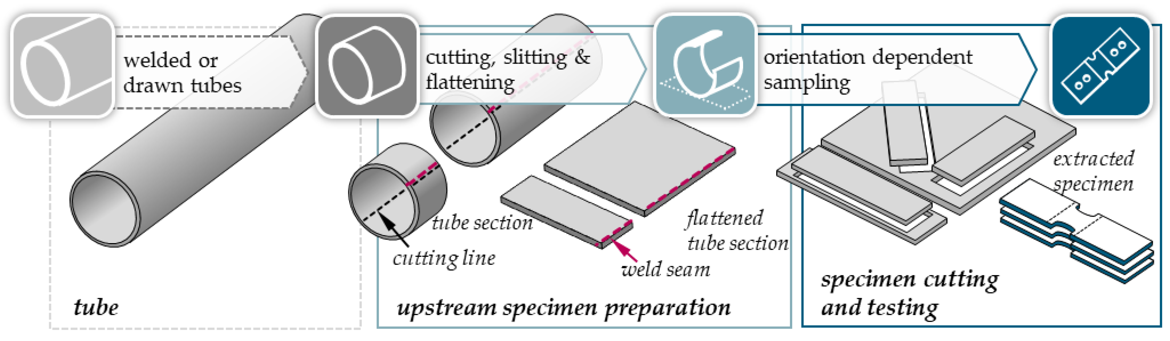
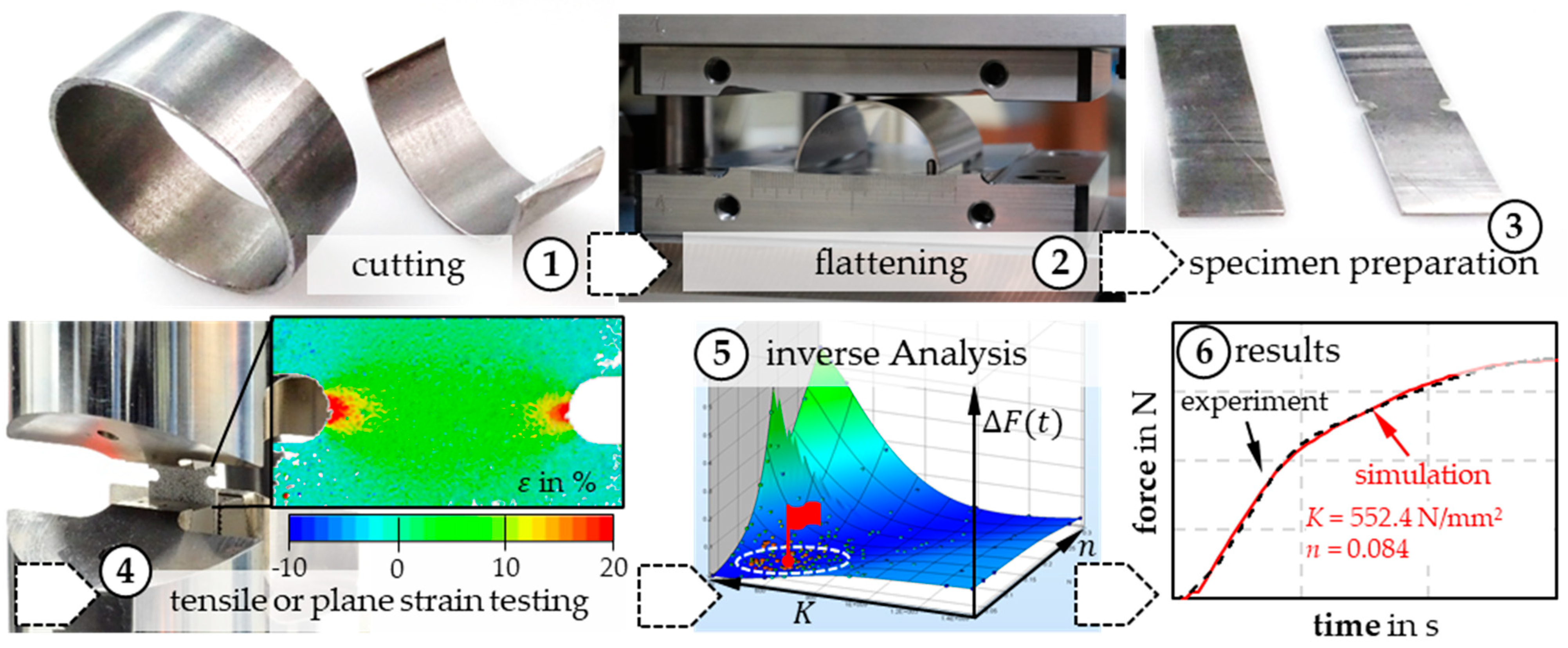
2.1. Solution Approach: Transfer of Plane Material Testing Methods to Curved Tubes by Flattening Combined with Numerical Parameter Identification

Instead of directly testing the curved tube, an intermediate flattening step was first used to produce a flat section from which different specimen shapes can be obtained for conventional materials testing on flat parts (see Figure 2). This procedure not only enables directional testing of tubes, but also an analysis of different strain states—e.g., by uniaxial tensile testing, shear tensile testing or plane strain testing. The latter is particularly interesting with regard to process-oriented material testing for hydroforming processes.
To enable these comprehensive testing options for tubes, the process of flattening is indispensable. However, it represents a significant intervention on the properties that cannot be neglected in material modeling. Due to the complexity of this forming process, an inverse evaluation method is provided that allows parameter identification of material models considering the flattening process numerically and the subsequent actual material testing in combination. In this process, the experimental test data (deformation detection by digital image correlation DIC, global force requirement) are compared, as a result variable, with an equivalent FE simulation model, and the difference in results is defined as an objective function. The identification of the searched, material-specific model parameters then results from an iterative optimization process under minimization of the objective function [32]. This so-called FEMU approach (Finite Element Method Updating) is widely used in the context of material modeling for FE simulations and is especially applied in the evaluation of test procedures with inhomogeneous deformation character [33].
For material testing with the use of flattened tube sections, the following steps for the identification of the parameters of a complex anisotropic material model for tubes can be summarized as shown schematically in Figure 3:
  • Separation of the tubes into ring sections and subsequent flattening, including measurement of relevant experimental quantities (force-time curve, geometric quantities).
  • Directional separation of specimens from the flattened sheet and conventional testing in a tensile testing machine, including measurement of force and strain quantities.
  • Construction of an inverse simulation model consisting of the combination of flattening and material testing, definition of the objective function as the difference between real and simulation results and inverse parameter identification by iterative simulation calculations.

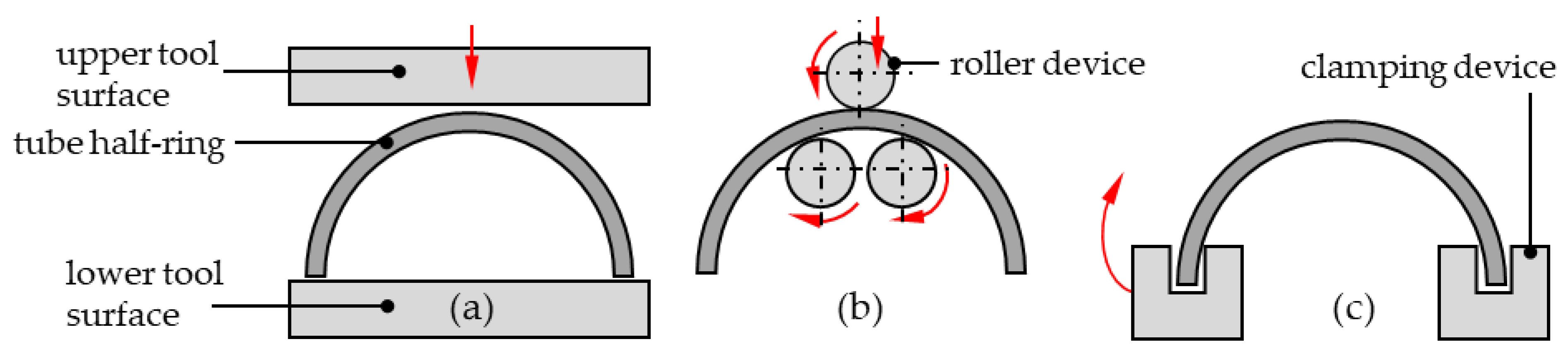
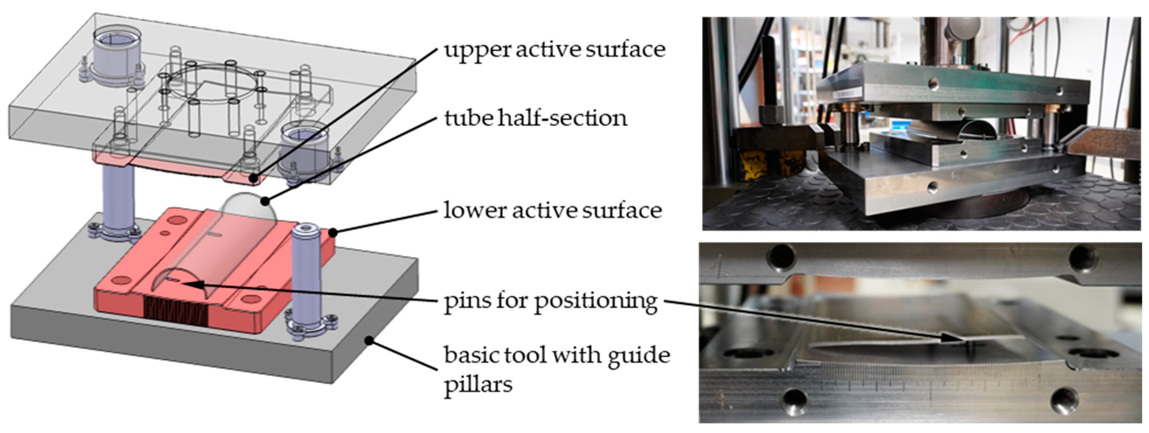
2.2. Strategies for Process Implementation of Specimen Flattening

For the proposed solution approach, from a technological point of view, the flattening step can be carried out with different tool principles and kinematics. Generally, the objective is to introduce bending deformation into the tube section to plastically reshape it into the desired planar form. Springback effects must be compensated as far as possible in order to produce a flat specimen section with flatness deviations within a maximum range of 1 mm, thus ensuring specimen preparation for subsequent tensile or PS testing with sufficient quality. In the present study, 3 principles of action for flattening were considered (shown schematically in Figure 4): flattening by pressing the tube ring between two tool surfaces that can be moved in translation relative to each other; flattening by incremental over-rolling with gradually increasing infeed amounts in a rolling device; and flattening by swing bending with single-sided clamping of the tube section. An evaluation of these technological variants, focusing on criteria of experimental execution as well as the subsequent inverse test evaluation, is listed in Table 2, partly based on preliminary numerical studies.
Considering the different criteria summarized in Table 2, the variant of flattening by pressing in a die offers numerous advantages and is clearly superior to the other process variants. It was therefore further investigated. The comparatively simple implementation of flattening in a forming tool provides a robust experimental starting situation with well-defined geometric and kinematic boundary conditions, which can also be reproduced numerically with little effort.

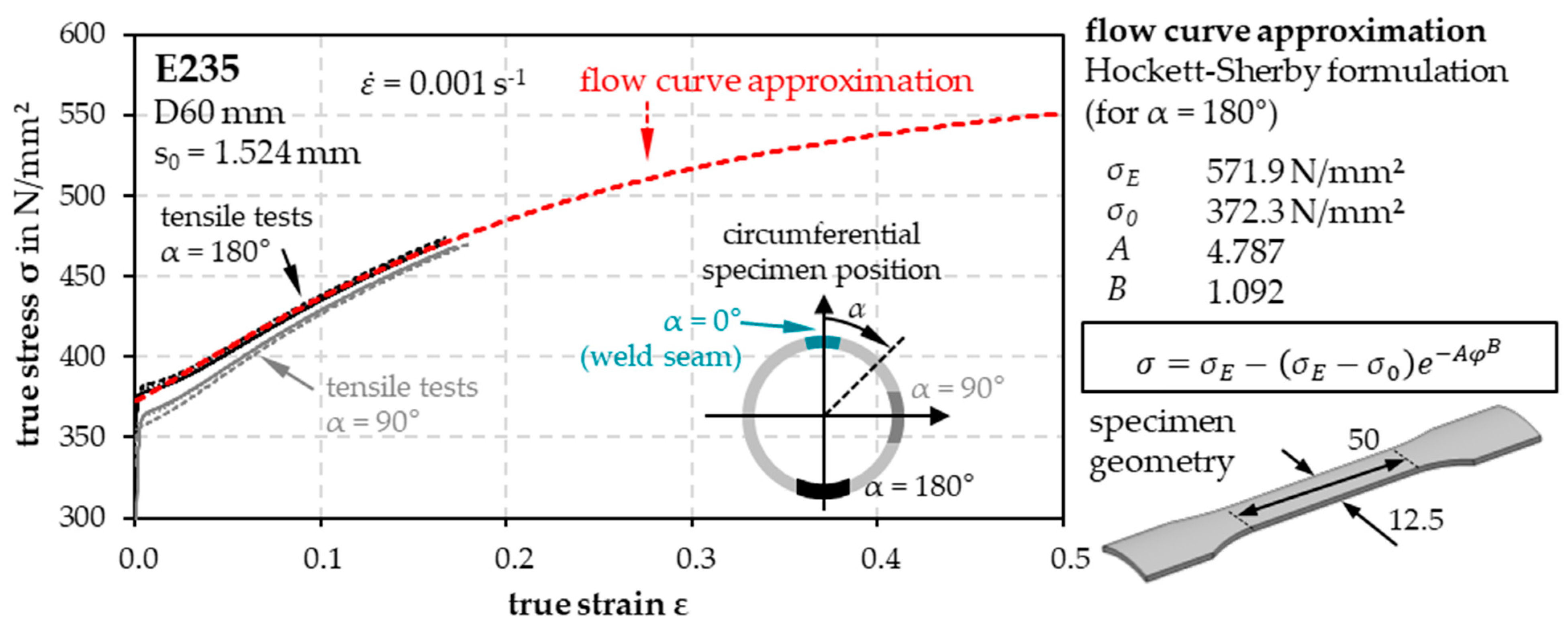
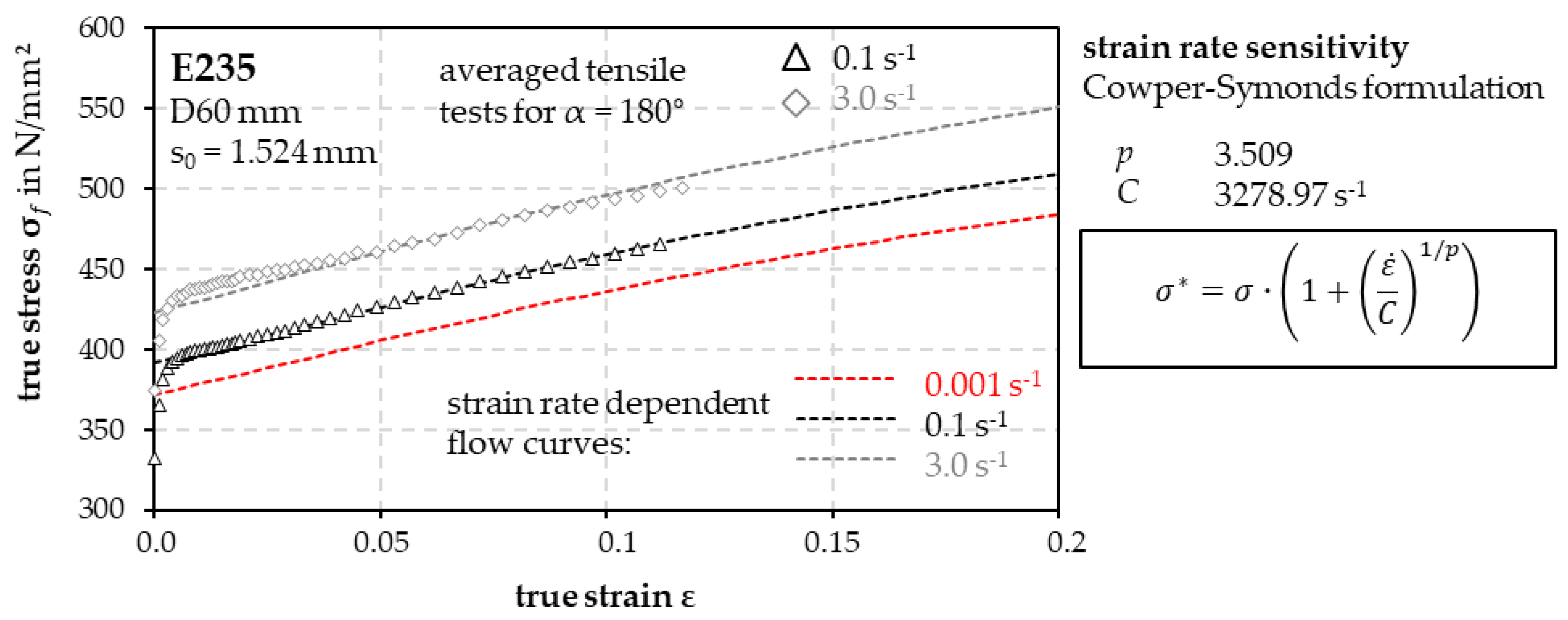
2.3. Material Modeling for Forming Simulation

An E235 steel with the chemical composition shown in Table 3 was used as test material for the following investigations. The tubes with a diameter of 60 mm and a length of 1 m have an average wall thickness of 1.524 mm. By measuring 4 sections at a distance of 300 mm on 2 tubes with a coordinate measuring machine Zeiss Prismo7S-ACC (Carl Zeiss, Oberkochen, Germany), the wall thickness profile was analyzed over the circumference (Figure 5). A characteristic feature is the reduced tube wall thickness in the area of the weld seam and 180° offset to it, which is related to the tube forming process. The standard deviation of the wall thickness is 0.026 mm.
For initial numerical studies of tube flattening, quasistatic tube tensile tests ( ε ˙ = 0.001 s−1; with slightly rounded clamps (adapted to the initial diameter of the used tube, see Figure 6) were first performed on wire-eroded specimens along the tube axis to estimate the elastic–plastic material properties for initial material modeling in the FE simulation. The true stress–true strain data in Figure 6 show that different tube tensile test positions relative to the weld result in position-dependent flow curves that differ in stress level but exhibit comparable hardening behavior.
Due to the largest local wall thickness reduction, only the removal position opposite the weld seam (180°) was considered for further investigation. The averaged, experimentally determined flow curves were approximated using the Hockett–Sherby approach [34]. In addition, for extended simulation studies in the context of strain-rate-sensitive measurement modeling, tube tensile tests were also performed longitudinally to the tube axis at higher strain rates. The strain rate sensitivity was taken into account in the material model according to the approach of Cowper–Symonds [35] (Figure 7).

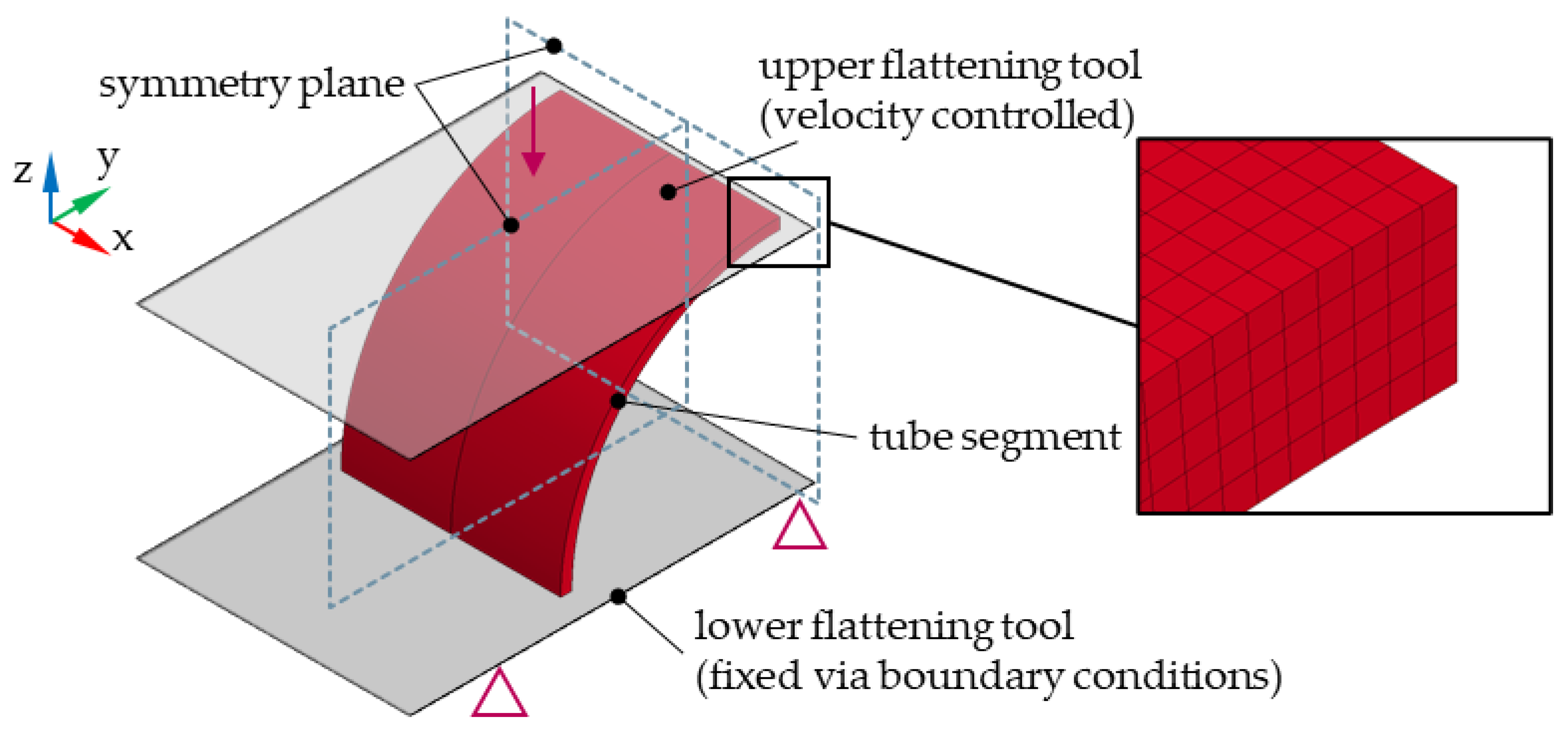
2.4. Simulation Model

The approximations of the quasistatic yield curve and strain rate sensitivity modeling were implemented in the anisotropic material model MAT_133 (yield locus approach Barlat 2000 [36]) for subsequent explicit simulations of flattening in LS-DYNA (DYNAmore GmbH, Stuttgart, Germany), solver version mpp R12.0. Based on the existing longitudinal tensile test data, isotropic behavior is assumed regarding the r-values and flow stresses in different rolling directions as well as the biaxial flow stress. The FE model setup is shown in Figure 8. The tube ring section is represented as a volume mesh using symmetric boundary conditions with five elements over the wall thickness (element edge length 0.3 mm). The initially flat tool surfaces are implemented as rigid die surfaces. The lower tool surface is fixed in space and the upper tool surface is moved, displacement-controlled, at a target speed of 3 mm/s. A simple Coulomb friction model with friction coefficient 0.15 is used.

3. Results and Discussion

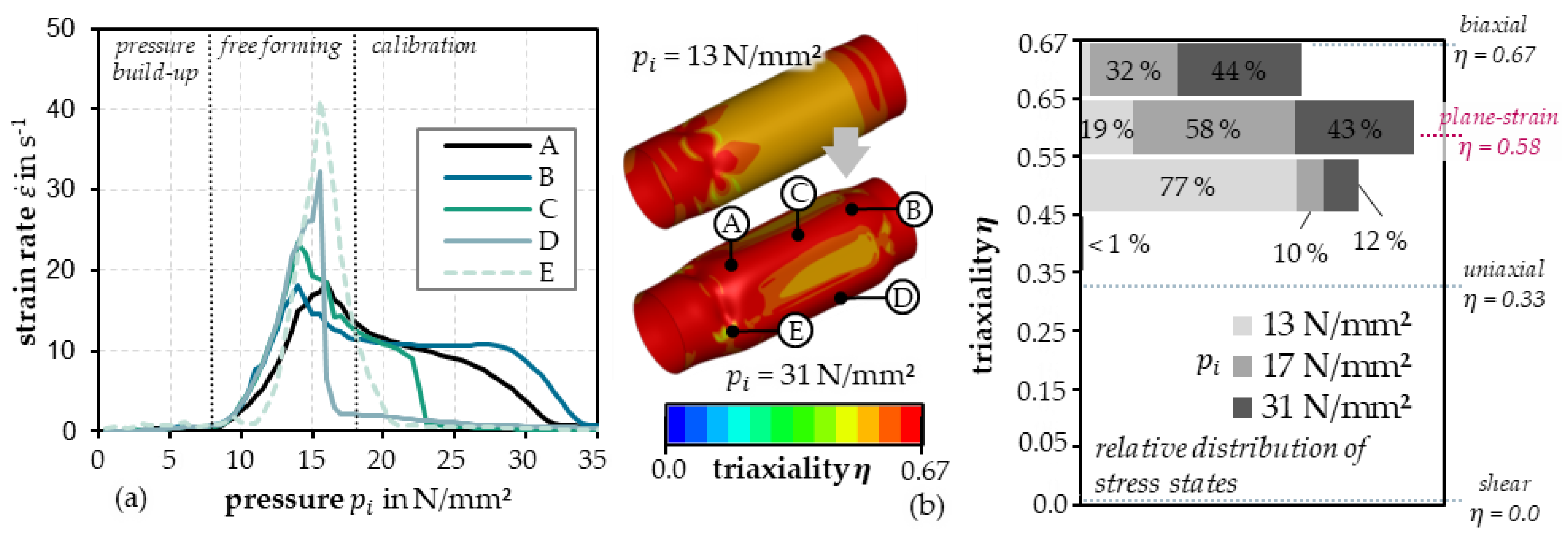
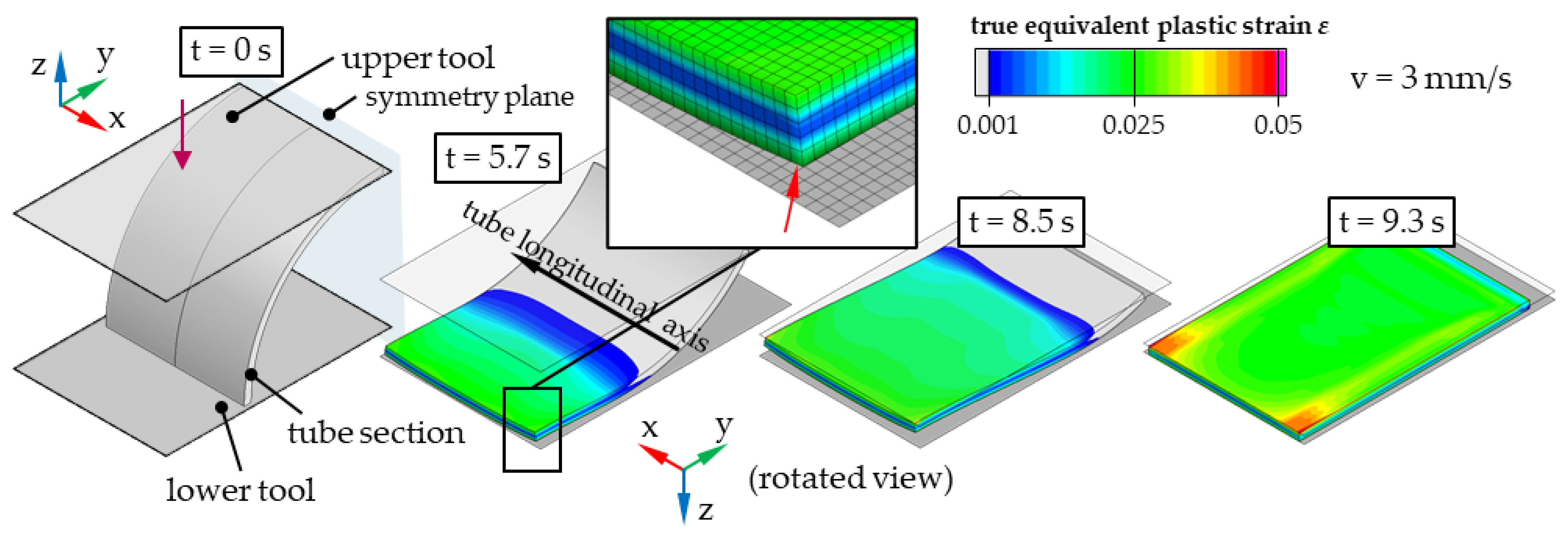
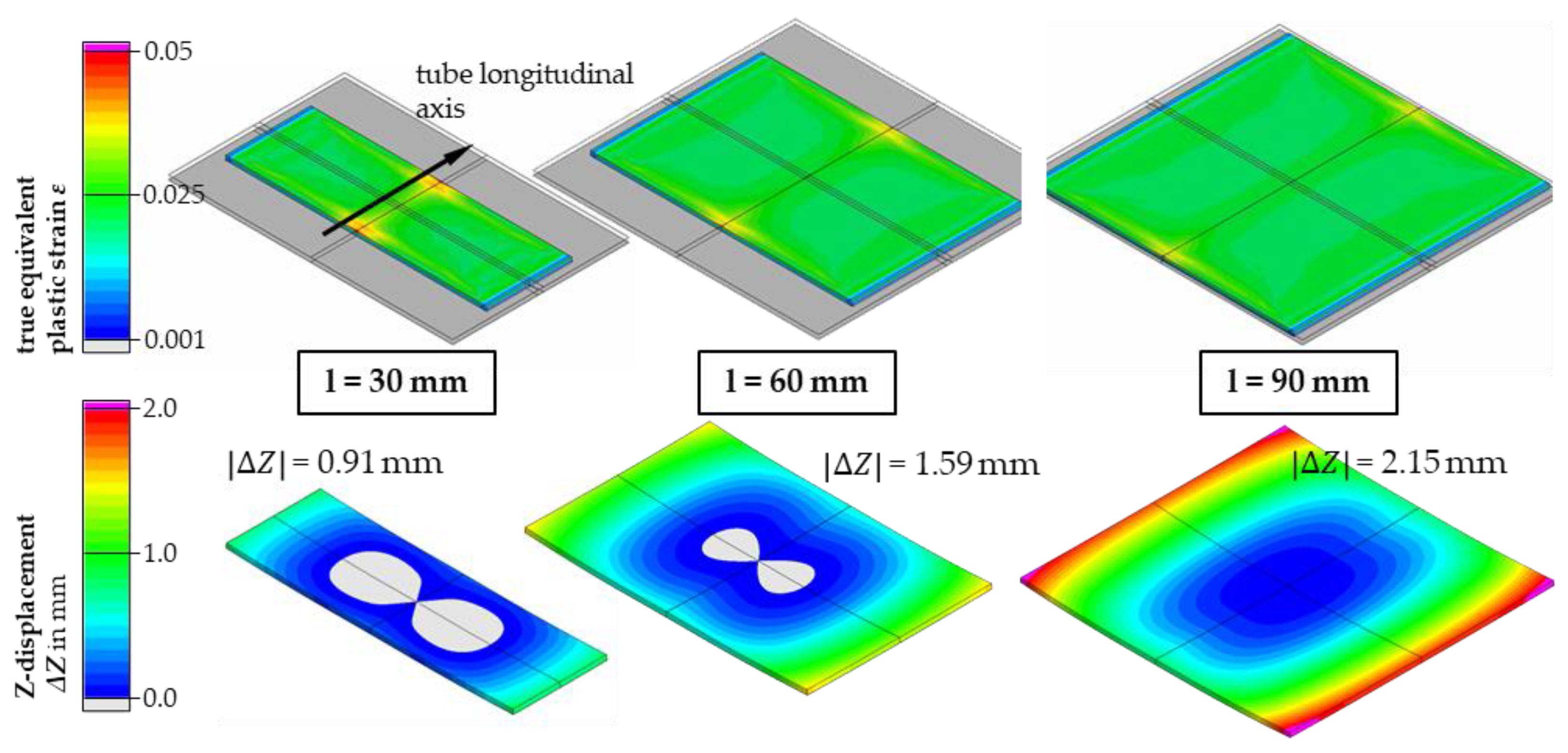
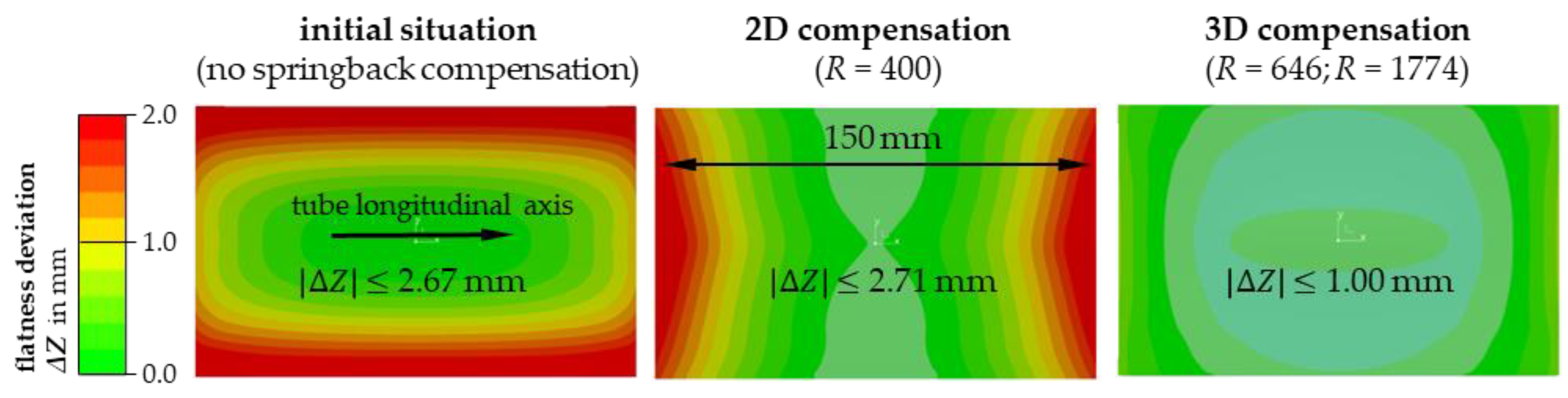
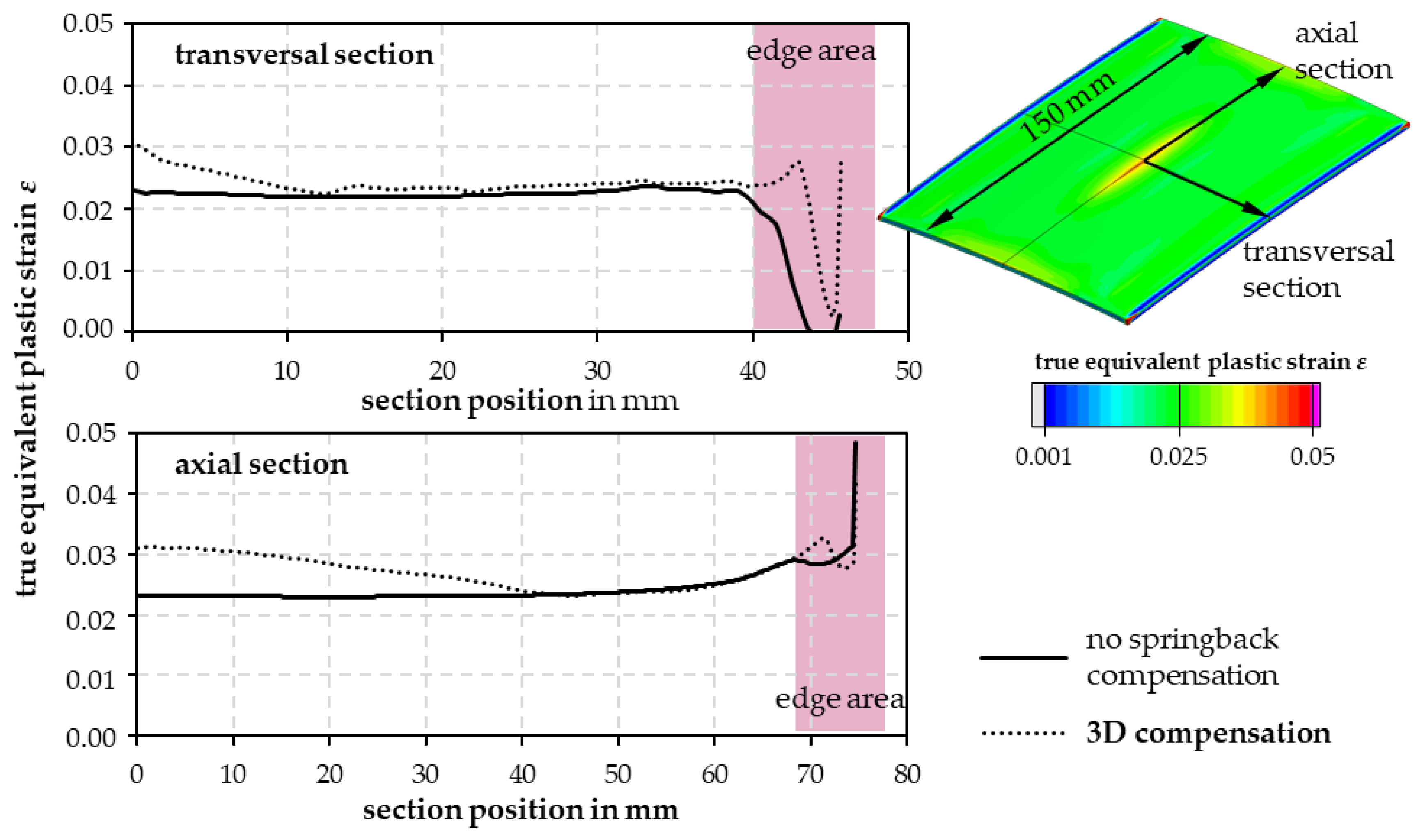
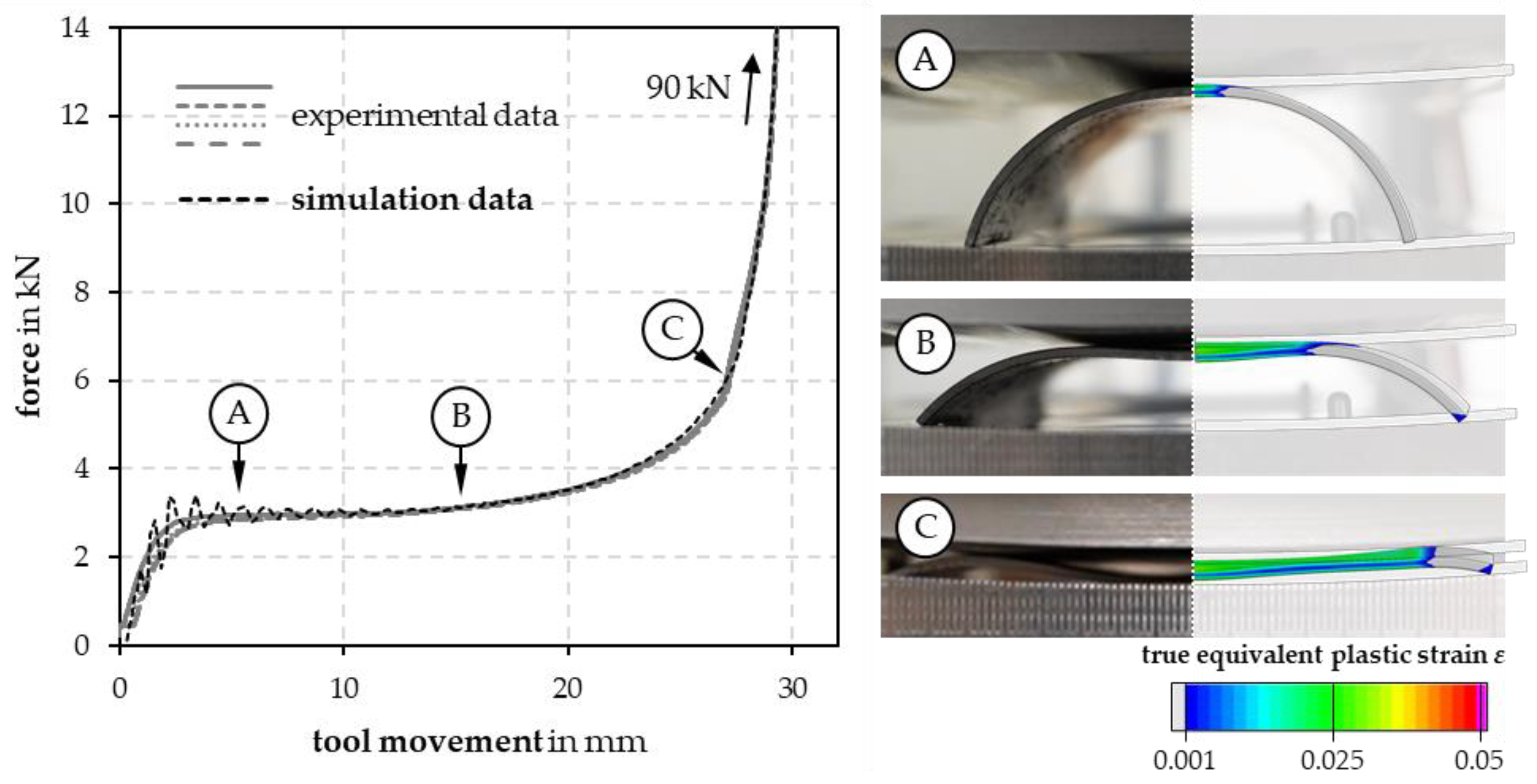
3.1. Simulation of Tube Section Flattening

The closing movement of the die surfaces gradually introduces an elastic, then plastic, bending deformation into the tube section, which spreads outwards starting from the plane of symmetry (Figure 9). A characteristic feature here is the lifting of the tube ends from the underlying die surface, which is only flattened again as the closing movement progresses. The true equivalent plastic strains caused are only slightly inhomogeneous in the area due to the mentioned edge effects. In the first reference case with a tube section width of 30 mm, true equivalent plastic strains caused by the compression deformation of the inner tube surface range from 2.5 to 4.5%. Homogeneous bending deformation was observed in the central specimen area.
The use of long tube sections is advantageous for the subsequent orientation-dependent preparation of samples and the provision of as many samples as possible from a flattened tube section. For this reason, simulations were carried out with different tube section lengths to analyze the influence of tube section length on the strain distribution and flatness deviations caused. Figure 10 shows that the magnitude of the edge effects remains approximately the same, so that a relatively larger area with an approximately homogeneous strain state can be provided when longer tube sections are subjected to flattening. Longer tube sections require greater forming forces for complete flattening, which may lead to practical limitations in later experimentation if, for example, universal testing machines are to be used for flattening instead of larger presses. In addition, longer tube sections lead to more pronounced springback, which can complicate the subsequent cutting out of samples and further material testing. Regardless of the tube section length, the computed wall thickness changes are very small (<1 µm) due to the dominant bending deformation.
The use of purely flat die surfaces leads to significant springback effects for longer tube section lengths. To compensate for these springback effects, 2D compensation was first implemented with a uniform radius of curvature R = 400 mm based on the initial simulation studies, so that the tube section is bent more in the tangential direction. This approach can significantly improve springback effects for a 150 mm long tube section in the middle area, as demonstrated by the simulation results in Figure 11. In this case, however, the tube ends still deform back in the axial direction, so the resulting flatness of the tube section is not improved. Only the use of a 3D curved surface, generated by superimposing a tangential (R = 646 mm) with an axial (R = 1774 mm) curvature, significantly improves this situation, so a reasonable flatness deviation of 1.0 mm is predicted by the simulation for the present comparison case.
Tube section flattening with 3D compensation in favor of improved specimen flatness is accompanied by a slightly increased inhomogeneity of the strain distribution (Figure 12 Neglecting the edge areas, this results in maximum true equivalent plastic strains between 2.2% and 3.1%. The largest differences result tangentially and axially in each case in the edge areas, which, however, are usually cut off by the subsequent sample cutting or are outside the subsequent specimen test area.

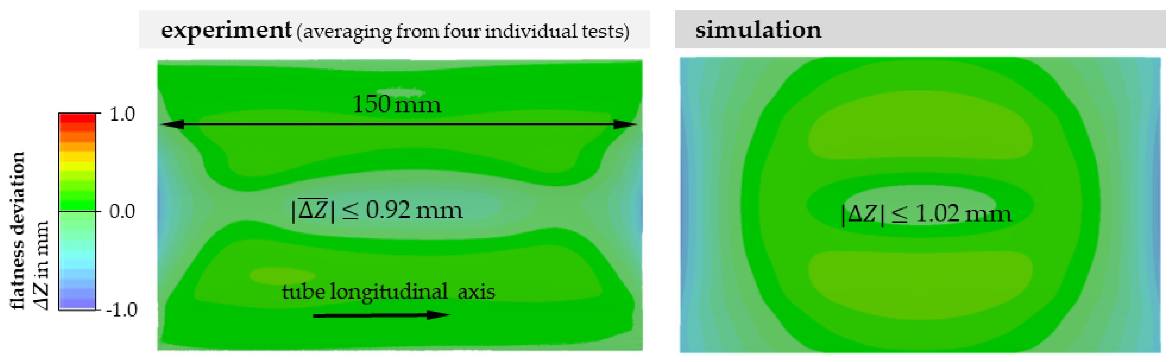
3.2. Experimental Validation of the Flattening Simulation

Based on the simulation studies, a test tool for the flattening of 150 mm long tube sections (D60) was designed and manufactured to validate the results experimentally (Figure 13). The concept presented in Section 2.2 with 3D compensation was used due to the predicted improved flatness of the tube sections after flattening.
The test die was installed in a ZwickRoell 100 kN (ZwickRoell, Ulm, Germany) universal testing machine in order to implement force measurement during forming. Repeated accurate positioning of the tube sections was achieved by means of spring-loaded positioning pins. The tube sections were separated from the tube by milling, with a continuous supply of coolant to prevent thermal influence. The 150 mm long tube half shells were then flattened at a constant closing speed of 3 mm/s until a forming force of 90 kN was reached.
The experimentally determined force–displacement curves (Figure 14) generally show good repeatability. Coupled with the evaluation of the gradual flattening of the tube half shell in the die, the characteristic stages of initial contact, incipient deformation with lifting of the middle tube area from the upper die surface and subsequent pressing down under sharply increasing force requirements can be analyzed in comparison to the forming simulation. Based on the comparison of the force–displacement curves, a good accuracy of the simulation can already be demonstrated. To evaluate the resulting flatness, the former outer tube surfaces of the flattened tube sections were scanned in a 3D profilometer VR-5000 (Keyence, Neu-Isenburg Germany) and rotated onto a flat reference surface to characterize flatness deviations. On the basis of four individual tests for flattening on the test tool, a mean flatness deviation of 0.92 mm was measured, which is assessed as sufficient for the purpose of the subsequent cutting out of samples (Figure 15).
Local differences between simulated and experimentally measured flatness deviations occur primarily at the specimen corners because the simulation predicts a lower amount of springback (maximum deviation: 0.63 mm). The reasons for this may be the assumed isotropy of the r-values and the initial yield stresses due to a lack of direction-dependent tensile test data. Furthermore, an influence of the real wall thickness distribution on the springback behavior is also possible, as this was not considered in the simulation model investigated. However, the repeatability of the experiments with respect to the resulting flatness deviation is satisfactory (standard deviation 0.045 mm). The nominal flatness deviations between the simulation and experiment are also minor (average deviation: 0.13 mm).

4. Conclusions

Expanding on the current limitations of the parameterization of complex, anisotropic material models for tubes, a new approach for orientation-dependent material testing of tubes is proposed. The test methodology requires an intermediate step of flattening and subsequent inverse parameter identification due to the introduced bending deformation. In the present work, this flattening step has been studied in detail numerically and experimentally. Flattening by pressing was identified as the most suitable variant and subsequently optimized by further simulations with a focus on springback compensation. The maximum true equivalent plastic strains caused by bending deformation are comparatively low ( ε m a x = 3.1%) and largely homogeneously distributed. The simulation results were validated experimentally, with good agreement in terms pressing forces and sample flatness deviation (maximum simulation deviation of 0.13 mm). These results demonstrate that the simulation model based on strain-rate-dependent longitudinal tube tensile tests already provides a highly accurate description of the tube section flattening. Tube sections taken from tubes (steel E235) with a diameter of 60 mm and a mean wall thickness of 1.524 mm were successfully flattened with a mean remaining flatness deviation of Δ Z ¯ = 0.92 mm using 3D-compensated die surfaces. This investigation provides the first basis for establishing a reproducible initial condition for further directional uniaxial tests on flattened tube sections and for evaluating them by inverse simulation-based parameter identification, taking into account the flattening process.
Future investigations will therefore clarify how the process of flattening responds to parameter variations in a complex anisotropic material model when preparing for an inverse parameter identification for subsequent tensile testing. In addition, the influence of the disturbance caused by friction in flattening will be investigated. The transferability to other diameters and wall thicknesses must also be examined, especially in the context of the compensation strategy presented.

Author Contributions

Conceptualization, F.R., S.W. and V.P.; methodology, F.R.; simulation, F.R.; validation, F.R.; investigation, S.F.; writing—original draft, F.R.; writing—review and editing, F.R., S.W., S.F., M.F.-X.W. and V.P.; visualization, F.R.; supervision, V.K., M.F.-X.W. and V.P.; project administration, F.R. and S.F.; funding acquisition, M.F.-X.W. and V.P. All authors have read and agreed to the published version of the manuscript.

Funding

This research was funded by the German Research Foundation (DFG), grant number 464455227.

Data Availability Statement

Not applicable.

Conflicts of Interest

The authors declare no conflict of interest.

References

  1. Bruschi, S.; Altan, T.; Banabic, D.; Bariani, P.F.; Brosius, A.; Cao, J.; Ghiotti, A.; Khraisheh, M.; Merklein, M.; Tekkaya, A.E. Testing and modelling of material behaviour and formability in sheet metal forming. CIRP Ann. 2014, 63, 727–749. [Google Scholar] [CrossRef]
  2. Merklein, M.; Rosenschon, M. Verbesserung des Qualifizierungsprozesses von Bauschinger-Parametern Durch Wechselbiegeversuche; EFB-Forschungsbericht EFB-471: Hannover, Germany, 2017. [Google Scholar]
  3. Reuther, F.; Mosel, A.; Freytag, P.; Lambarri, J.; Degenkolb, L.; Werner, M.; Winter, S. Numerical and experimental investigations for hot metal gas forming of stainless steel X2CrTiNb18. Procedia Manuf. 2019, 27, 112–117. [Google Scholar] [CrossRef]
  4. Neugebauer, R. Hydro-Umformung; Springer: Berlin/Heidelberg, Germany, 2007. [Google Scholar]
  5. Winter, S.; Schmitz, F.; Clausmeyer, T.; Tekkaya, A.E.; Wagner, M.F.-X. High temperature and dynamic testing of AHSS for an analytical description of the adiabatic cutting process. IOP Conf. Ser. Mater. Sci. Eng. 2017, 181, 12026. [Google Scholar] [CrossRef]
  6. Winter, S.; Werner, M.; Haase, R.; Psyk, V.; Fritsch, S.; Böhme, M.; Wagner, M.F.X. Processing Q&P steels by hot-metal gas forming: Influence of local cooling rates on the properties and microstructure of a 3rd generation AHSS. J. Mater. Process. Technol. 2021, 293, 117070. [Google Scholar] [CrossRef]
  7. Reblitz, J.; Reuther, F.; Trân, R.; Kräusel, V.; Merklein, M. Numerical and Experimental Investigations on the Mechanical Properties of Milled Specimens from an AA7020 Tube. KEM 2022, 926, 1949–1958. [Google Scholar] [CrossRef]
  8. Offermanns, S. Verhalten Dünnwandiger Austenitischer Rohre bei Wasserstoff-Sauerstoff-Detonation; Materialprüfungsanstalt (MPA); Universität Stuttgart: Stuttgart, Germany, 2016; ISBN 3946789005. [Google Scholar]
  9. Arsene, S.; Bai, J. A New Approach to Measuring Transverse Properties of Structural Tubing by a Ring Test. J. Test. Eval. 1996, 24, 386. [Google Scholar] [CrossRef]
  10. Zhou, J.-B.; Sun, P.-Y.; Zhou, C.-Y.; He, X.-H. Experimental characterization of anisotropic tensile mechanical behavior of pure titanium tube. J. Iron Steel Res. Int. 2019, 26, 91–101. [Google Scholar] [CrossRef]
  11. Bae, B.K.; Seok, C.S.; Koo, J.M.; Kim, H.I.; Murty, K.L. Creep Rupture Studies of Zirlo Tubing Using Ring Tensile Specimen. KEM 2006, 321–323, 565–569. [Google Scholar] [CrossRef]
  12. Hellouin de Menibus, A.; Auzoux, Q.; Besson, J.; Crépin, J. Temperature increase of Zircaloy-4 cladding tubes due to plastic heat dissipation during tensile tests at 0.1–10 s −1 strain rates. J. Nucl. Mater. 2014, 454, 247–254. [Google Scholar] [CrossRef]
  13. Cazalis, B.; Desquines, J.; Carassou, S.; Le Jolu, T.; Bernaudat, C. The plane strain tests in the PROMETRA program. J. Nucl. Mater. 2016, 472, 127–142. [Google Scholar] [CrossRef]
  14. Khalfallah, A.; Ktari, Z.; Leitão, C.; Fernandes, J.V. New Mandrel Design for Ring Hoop Tensile Testing. Exp. Tech. 2021, 45, 769–787. [Google Scholar] [CrossRef]
  15. Mousavi, F.; Hashemi, R.; Madoliat, R. Measurement of directional anisotropy coefficients for AA7020-T6 tubes and prediction of forming limit curve. Int. J. Adv. Manuf. Technol. 2018, 96, 1015–1023. [Google Scholar] [CrossRef]
  16. Woo, D.M. Tube-Bulging under Internal Pressure and Axial Force. J. Eng. Mater. Technol. 1973, 95, 219. [Google Scholar] [CrossRef]
  17. Hielscher, C. Entwicklung Eines Halbzeugprüfverfahrens für das Innenhochdruck-Umformen von Hohlprofilen; Shaker: Aachen, Germany, 2001; ISBN 3-8265-8827-4. [Google Scholar]
  18. Koc, M.; Aue-u-lan, Y.; Altan, T. On the Characteristics of Tubular Materials for Hydroforming-Experimentation and Analysis. Int. J. Mach. Tools Manuf. 2001, 41, 761–772. [Google Scholar] [CrossRef]
  19. von Breitenbach, G. Methode zur Analyse, Bewertung und Optimierung der Prozesskette Profiliren Längsnahtgeschweißter Rohre für das Innenhochdruck-Umformen. Dissertation Thesis, Technische Universität Darmstadt, Darmstadt, Germany, 2007. [Google Scholar]
  20. Steinheimer, R. Prozesssicherheit beim Innenhochdruck-Umformen; Shaker: Aachen, Germany, 2006; ISBN 9783832249809. [Google Scholar]
  21. Vitu, L.; Boudeau, N.; Malécot, P.; Michel, G.; Buteri, A. Evaluation of models for tube material characterization with the tube bulging test in an industrial setting. Int. J. Mater. Form. 2018, 11, 671–686. [Google Scholar] [CrossRef]
  22. Elsenheimer, D.; Groche, P. Determination of material properties for hot hydroforming. Prod. Eng. Res. Dev. 2009, 3, 165–174. [Google Scholar] [CrossRef]
  23. Kuwabara, T.; Sugawara, F. Multiaxial tube expansion test method for measurement of sheet metal deformation behavior under biaxial tension for a large strain range. Int. J. Plast. 2013, 45, 103–118. [Google Scholar] [CrossRef]
  24. Zhang, Z.; Li, B.; Manabe, K.-I.; Sato, H. Evaluation of Circumferential Mechanical Properties of Tubular Material by Flaring Test. Metals 2022, 12, 764. [Google Scholar] [CrossRef]
  25. Daxner, T.; Rammerstorfer, F.G.; Fischer, F.D. Instability phenomena during the conical expansion of circular cylindrical shells. Comput. Methods Appl. Mech. Eng. 2005, 194, 2591–2603. [Google Scholar] [CrossRef]
  26. Lee, M.-G.; Korkolis, Y.P.; Kim, J.H. Recent developments in hydroforming technology. Proc. Inst. Mech. Eng. Part B J. Eng. Manuf. 2015, 229, 572–596. [Google Scholar] [CrossRef]
  27. Király, M.; Antók, D.M.; Horváth, L.; Hózer, Z. Evaluation of axial and tangential ultimate tensile strength of zirconium cladding tubes. Nucl. Eng. Technol. 2018, 50, 425–431. [Google Scholar] [CrossRef]
  28. Fresnel, H.; Grolleau, V.; Longère, P.; Rio, G.; Hardy, P. Characterization of the shear behaviour of a thin-walled tubular material. Thin-Walled Struct. 2009, 47, 295–303. [Google Scholar] [CrossRef]
  29. Macherauch, E.; Zoch, H.-W. V48 Torsionsverformung. In Praktikum in Werkstoffkunde: 95 Ausführliche Versuche aus Wichtigen Gebieten der Werkstofftechnik, 12; überarb und erw. Aufl.; Macherauch, E., Zoch, H.-W., Eds.; Springer: Wiesbaden, Germany, 2014; pp. 373–379. ISBN 978-3-658-05037-5. [Google Scholar]
  30. Biermann, H.; Krüger, L. Moderne Methoden der Werkstoffprüfung; WILEY-VCH Verlag GmbH & Co. KGaA: Weinheim, Germany, 2015; ISBN 9783527670673. [Google Scholar]
  31. Pepelnjak, T.; Šašek, P.; Kudlaček, J. Upsetting Analysis of High-Strength Tubular Specimens with the Taguchi Method. Metals 2016, 6, 257. [Google Scholar] [CrossRef]
  32. Avril, S.; Bonnet, M.; Bretelle, A.-S.; Grédiac, M.; Hild, F.; Ienny, P.; Latourte, F.; Lemosse, D.; Pagano, S.; Pagnacco, E.; et al. Overview of Identification Methods of Mechanical Parameters Based on Full-field Measurements. Exp. Mech. 2008, 48, 381–402. [Google Scholar] [CrossRef]
  33. Küsters, N.; Brosius, A. Semi-analytic parameter identification for complex yield functions. MATEC Web. Conf. 2016, 80, 10002. [Google Scholar] [CrossRef]
  34. Hockett, J.E.; Sherby, O.D. Large strain deformation of polycrystalline metals at low homologous temperatures. J. Mech. Phys. Solids 1975, 23, 87–98. [Google Scholar] [CrossRef]
  35. Cowper, G.R.; Symonds, P.S. Strain-Hardening and Strain-Rate Effects in the Impact Loading of Cantilever Beams; Brown University Division of Applied Mathematics Report No. 28; Brown University: Providence, RI, USA, 1957. [Google Scholar]
  36. Banabic, D. Sheet Metal Forming Processes; Springer: Berlin/Heidelberg, Germany, 2010; ISBN 978-3-540-88112-4. [Google Scholar]
Figure 1. Exemplary hydroforming simulation for process design; strain rate characteristics of discrete points with local maxima of up to ε ˙ = 40 s−1 (a); development and distribution of stress triaxiality under steadily increasing internal pressure pi (b); plane strain conditions dominate.
Jmmp 07 00091 g001
Figure 2. Schematic representation of the testing procedure proposed in the present paper: flattening of curved tube sections to obtain specimens for conventional material testing on flat parts.
Jmmp 07 00091 g002
Figure 3. Proposed step-by-step solution for material testing of tubes.
Jmmp 07 00091 g003
Figure 4. Process strategies for specimen flattening: (a) flattening by pressing; (b) flattening by rolling; (c) flattening by swing bending.
Jmmp 07 00091 g004
Figure 5. Tube thickness analysis for different orientations relative to the weld seam.
Jmmp 07 00091 g005
Figure 6. Quasistatic flow curves of E235 tubes and flow curve approximation using a Hockett-Sherby formulation.
Jmmp 07 00091 g006
Figure 7. Strain-rate-dependent flow curves of E235 tubes and strain-rate-sensitive modeling.
Jmmp 07 00091 g007
Figure 8. FE model for the simulation of tube flattening in LS-DYNA.
Jmmp 07 00091 g008
Figure 9. Simulation results of flattening with tube section length 30 mm and closing speed 10 mm/s using flat die surfaces.
Jmmp 07 00091 g009
Figure 10. Simulation of flattening with variable tube section length. Influence on the true equivalent plastic strain and the resulting springback amounts when using flat tool surfaces.
Jmmp 07 00091 g010
Figure 11. Simulated flatness deviation in Z-direction of flattened tube sections using different compensation strategies.
Jmmp 07 00091 g011
Figure 12. True equivalent plastic strain (compression deformation of the inner tube surface) in sections after flattening using flat die surfaces and 3D compensation.
Jmmp 07 00091 g012
Figure 13. Tool concept with 3D compensation for tube section lengths of up to 150 mm (left); test setup and flattened tube sections (right).
Jmmp 07 00091 g013
Figure 14. Force–displacement curves of experiments and simulation results (left); stages of flattening, comparison of experiments and simulation at three different deformation stages A–C (right).
Jmmp 07 00091 g014
Figure 15. Flatness deviation of the tube sections flattened in the test tool (left); predicted flatness deviation of the simulation result (right).
Jmmp 07 00091 g015
Table 1. Summary evaluation of the existing testing concepts of tubes.
AB
Group A: dominant test methods in the hydroforming context
Group B: other established tube testing methods
longitudinal tube
tensile test
ring hoop
tension test
tube bursting
test
tube flaring
test
tensile test (entire
tube cross section)
torsion testlateral ring
compression tests
ring expansion test
Orientation-dependent testing±
Preferred test direction: transversal++++
Strain-rate-dependent testing+±±±++±
Hydroforming-specific strain state±+
Isolated testing of weld seam++
Requirements: frictionless testing+±++++
Table 2. Summary evaluation of the existing testing concepts of tubes.
Flattening by:PressingIncremental RollingSwing Bending
Criteria from the context of experimental realization
kinematics++simple− −complex, gradual forming with several incremental rolling steps necessarycomplex
forming machine and tool devices+easy, can be implemented in conventional tensile testing machines with toolspecial rolling device necessary, very small roll diameters requiredspecial forming and clamping device necessary
material utilization++high, only small edge areas are not usable later+/−medium, there are always edge areas that cannot be rolled over+/−medium, big clamping areas are necessary
flatness of specimen+good, springback compensation with overbending possible+/−gradually adjustable by roller movement+springback compensation with overbending or -stretching possible
Criteria from the context of inverse evaluation
amount of plastic deformation+/−small, only slight inhomogeneities++small, no inhomogeneities+/−small, only slight inhomogeneities
numerical modelling and calculation effort++only small computation times, geometrically well defined− −high computation times due to incremental steps+/−medium computation times due to kinematics
experimental data evaluation for inverse approach+forming force can be measured well, strains or thinning only offlineforming force only measurable with special device, strains or thinning only offlineforming force only measurable with special device, strains or thinning only offline
influence of frictionlocal contact, static and dynamic friction+only due to rolling++no influence
Legend: ++ very good, + good, +/− satisfying, − sufficient, − − inadequate.
Table 3. Chemical analysis of the used steel E235.
Chemical Composition (wt.-%)CMnSiPSFe
According to EN 10027-2max. 0.17max. 1.2max. 0.35max. 0.045max. 0.045balanced
Used material0.080.600.0140.0070.010balanced
Disclaimer/Publisher’s Note: The statements, opinions and data contained in all publications are solely those of the individual author(s) and contributor(s) and not of MDPI and/or the editor(s). MDPI and/or the editor(s) disclaim responsibility for any injury to people or property resulting from any ideas, methods, instructions or products referred to in the content.

