Article

Recoater-Induced Distortions and Build Failures in Selective Laser Melting of Thin-Walled Ti6Al4V Parts

1
International Center for Numerical Methods in Engineering (CIMNE), Polytechnic University of Catalonia (UPC), Edificio C1, Campus Norte, Gran Capitán s/n, 08034 Barcelona, Spain
2
Leitat Technological Center, C/De la Innovació, 08225 Terrassa, Barcelona, Spain
*
Author to whom correspondence should be addressed.
J. Manuf. Mater. Process. 2023, 7(2), 64; https://doi.org/10.3390/jmmp7020064
Submission received: 31 January 2023 / Revised: 1 March 2023 / Accepted: 9 March 2023 / Published: 13 March 2023
(This article belongs to the Special Issue Editorial Board Members’ Collection Series: Additive Manufacturing)

Abstract

:
Additively manufactured thin-walled structures through selective laser melting (SLM) are of great interest in achieving carbon-neutral industrial manufacturing. However, residual stresses and warpages as well as recoater crashes often occur in SLM, leading to the build failure of parts, especially for large-scale and lightweight geometries. The challenge in this work consists of investigating how the recoater affects the warpage and (sometimes) causes the failure of different thin-walled Ti6Al4V parts (wall thickness of 1.0 mm). All these parts are printed on the same platform using a commercial SLM machine. After the loose powder removal and before the cutting operation, a 3D-scanner is used to obtain the actual warpage of each component. Next, an in-house coupled thermo-mechanical finite element model suitable for the numerical simulation of the SLM process is enhanced to consider the recoater effects. This numerical framework is calibrated to predict the thin-walled warpage as measured by the 3D-scanner. The combination of numerical predictions with experimental observations facilitates a comprehensive understanding of the mechanical behavior of different thin-walled components as well as the failure mechanism due to the recoater. The findings show that the use of a higher laser energy input causes larger residual stresses and warpage responsible for the recoater crashes. Finally, potential solutions to mitigate the warpage and the recoater crashes in the SLM of lightweight structures are assessed using the validated model.

1. Introduction

Selective Laser Melting (SLM) is one of the most used Additive Manufacturing (AM) technologies allowing for the cost-effective production of metallic components with highly complex geometries [1,2]. SLM is currently being adopted in different industrial sectors, such as bio-medical, aerospace and automotive engineering [3,4]. The SLM uses a laser heat source to selectively melt the metallic powder bed following a layer-by-layer sequence till completing the 3D printing of the components.
Figure 1 shows the steps of the SLM process: (1) the recoater blade spreads a new layer of metallic powder with a thickness of around 30~60 mm; (2) a high-energy laser beam selectively melts the powder that defines the actual cross-section of the component according to a pre-defined scanning sequence generated by the slicer; (3) the printing platform is lowered to accommodate a new powder layer; (4) steps (1)~(3) are repeated until completing the printing of the whole part; (5) the loose powder is removed and the printed components are cut away from the base plate [5].
In SLM processes, the high-energy laser is very localized and the metallic powder is melted at a very high scan speed (close to 1 m/s). Thus, a very small melting pool is formed so that sharp temperature gradients (up to 107 °C/m) and significant cooling rates often exceeding 105 °C/s are observed in the heat-affected zone surrounding the melting pool [6,7,8]. As a consequence, either large residual stresses (for thick components) or warpages (for thin-walled structures) are generated. Hence, the SLM process often fails because of excessive part distortion, cracking of the supporting structures due to the high residual stresses, and recoater crashes [9,10,11].
To reduce the carbon footprint, the manufacturing of lightweight structures is preferred, e.g., thin-walled titanium components used in the aerospace engineering sector, heat exchangers, and antennas [12,13,14,15,16,17,18,19]. Nonetheless, compared to thick and bulky components, the AM fabrication of lightweight parts is more challenging because they are more prone to warpages; as the building height increases, the mechanical constraint gradually reduces. Moreover, the temperature field increases because of the slow heat dissipation. Consequently, the residual stresses induced by the repeated laser melting and cooling processes generates large deformations, which increase with the printing height further from the building platform. When the vertical displacements at the top surface of the build exceed the pre-set thickness of the powder layer, the structural warpage of the build affects the recoating operation [20]. As a result: (i) the powder spreading is no longer uniform; (ii) the recoater deforms the underlying layers, plastifying the (hot) material; (iii) the warpage precludes the recoater’s movement, causing damages to the AM machine [21]; thus, the build-up fails before completing the whole printing.
Recoater crashes resulting from thermally-induced part deformations could be avoided by optimizing the process parameters, modifying the component design and its orientation in the building chamber, or optimizing the configuration of supporting structures [22,23,24,25,26,27,28]. For instance, Promoppatum et al. [25] investigated the influence of energy density (ED) on residual stresses and part deformations. They found that keyholing defects can be generated if the energy input is higher than 2.94 J/mm2, and an optimal ED of 2.0 J/mm2 is recommended. Wang et al. [26,27] studied how to improve the quality of the surface roughness of overhanging structures caused by the melting of the powder bed during SLM fabrication. They found that to avoid any damage to the recoating device, the use of low-energy input and short scanning tracks is recommended. Additionally, Yakout et al. [28] found that adopting excessively high energy power (>350 W) leads to improper layer melting, which favors the contact between the recoater and the asperities generated on the top surface of the build. Higher ED results in higher peak temperatures and a larger volume of the melting pool. Thus, higher thermal gradients and larger residual stresses are formed, contributing to more pronounced part warpages. Focusing on thin-walled geometries, characterized by poor structural stiffness, these distortions (e.g., vertical displacements) can cause the recoater crashes. Additionally, Le et al. [29] analyzed the quality of the powder bed as a function of the feedstock and different recoating strategies. Their results showed that rubber recoating blades with a larger contact surface area and mid-range recoating velocities (10–80 mm/s) yield more uniform and compact powder layers, improving the printing quality while reducing the risk of recoater damages. Finally, it was found that the recoating speed directly affects the inter-layer cooling time and, thus, the heat accumulated in the build as well as its mechanical response [30,31]. Hence, using the right recoating speed helps to reduce the risk of the recoater impacting the deformed geometry of the AM build.
Lightweight structures are a critical component of many functional products. Thus, the analysis of build failures related to part deformations and the powder recoating system is of paramount importance for promoting their industrial application. At present, trial-and-error approaches as well as the technician’s expertise operating the AM machines can prevent the recoater from crashing. Alternatively, numerical simulation provides a feasible and efficient approach to predict the thermal history and mechanical response during the whole AM process [32,33,34,35]. Thus, it is possible to identify the underlying cause of possible problems in the fabrication early and take the necessary measures to solve them. Kobir et al. [33] developed a thermomechanical modeling approach based on graph theory to predict the probability of the occurrence of recoater crashes in the SLM fabrication process and achieved high computational efficiency. Lu et al. [1] employed a coupled thermomechanical model to investigate the influence of the substrate design on the mechanical response in SLM of T-shaped Ti6Al4V parts. Their results showed that crack-free components can be printed by adding grooves within the substrate. Chakraborty et al. [10] numerically analyzed the in-process failure during the SLM process of thin-walled RENE65 and RENE108 parts. The finite element (FE) simulations of the AM process clearly show that the thermal stresses generated in thin-walled structures cause more pronounced warpages and, consequently, these light-weight structures are more prone to printing failures. Vastola et al. [35] simulated the SLM process to investigate the buckling phenomena of thin-walled tubular components, analyzing different structural designs. They found that part distortions can be mitigated by rounding the sharp edges in IN718 parts with a wall thickness of 0.4 mm. Li et al. [36] numerically studied the effect of the scan length on the deformation of thin-walled Ti6Al4V parts and found that the scan length of 4–6 mm is most suitable. Additionally, Chen et al. [37] used a layer-by-layer FE model to study the influence of the part dimension on the warpage of thin Ti6Al4V single-walls fabricated by SLM. They found that increasing the part thickness helps to reduce maximum deformation.
Recent studies suggested that the structure and size of grains formed during AM affect the strength and ductility of the printed material, as well as the residual stresses on a micro-scale [2,4]. However, for macro residual stresses and part deformations, these effects can be negligible when compared to the large thermal gradients induced by the high-energy laser beam in AM. Specifically, this work aims to understand the complicated interactions between the structural features of different thin-walled builds, thermal stresses, part deformation, and recoater effects on a macro-scale.
In this study, three kinds of thin-walled geometries are analyzed: single-wall, open, and closed structures. First, these structures are built using a SLM machine. Next, an in-house coupled thermo-mechanical FE software is enhanced to consider the interaction between the recoating system and the underlying printed layers. The validation and calibration of this model are accomplished by comparing the numerical predictions with the measured displacements obtained by a 3D-scanner. Finally, potential solutions are suggested to mitigate the component warpage induced by the AM process.

2. Experimental Campaign

The 3D printing fabrication is performed using a RENISHAW RenAM 500Q, (Wotton-under-Edge, UK) machine equipped with a 500 W YB-fiber laser system, with a wavelength of 1070 nm and a laser spot diameter of 75 μm. The AM takes place in a high-purity argon atmosphere in order to ensure a lower oxygen content (less than 1000 ppm) during the whole printing process.
In this work, gas-atomized Ti6Al4V powder with a particle size of 15~45 µm is used. The powder is dried in a vacuum oven (vacuum degree < 80 kPa) at 120 °C for 3.0 h. An annealed Ti6Al4V base-plate of 250 × 250 × 40 mm3 is adopted to build different thin-walled structures. The scanning sequence is based on a 67° rotating deposition pattern. Table 1 lists the optimized SLM processing parameters used in this research, guaranteeing the fabrication of fully dense Ti6Al4V parts. A relatively high ED of 6.12 J/mm2 is adopted to amplify the mechanical effects in lightweight parts.
Figure 2 shows the nominal CAD models of different thin-walled structures sent to the slicing tool to generate the scanning sequence for the SLM machine. After build-up; the actual printed parts are measured by the Breuckmann Smart SCAN3D scanner with a measurement accuracy of 0.015 mm. The corresponding displacements causing the part warpage are obtained by the Geomagic Control X software by comparing the scanned images with the nominal CAD geometries. The thin-walled structures are not cut from the substrate when their distortions are measured

3. Computational Simulation

A coupled thermo-mechanical FE model implemented in the in-house COMET software [38,39] is employed to simulate the SLM process. The fractional step method is used to obtain a staggered solution. Thus, the thermal problem is solved first, followed by the mechanical analysis, at each time-step of the AM process. A detailed description of the thermo-mechanical model used for AM can be found in previous publications [40,41].

3.1. Thermal Problem

The balance equation governing the transient thermal analysis [40] can be written as:
H ˙ = · q + Q ˙
where H ˙ is enthalpy rate, q is heat flux and Q ˙ is the volumetric heat source (per unit of volume). Here, Q ˙ is characterized by the total laser input P ˙ and the actual energy efficiency η p , applied in the melting-pool volume V m p t :
Q ˙ = η p P ˙ V m p t
The heat flux, q , is defined by Fourier’s law:
q = k T
where k is the (temperature-dependent) thermal conductivity, and T is the thermal gradient.
Three different heat dissipation mechanisms are considered: (i) the heat conduction through the substrate (the platform or previously deposited layers) and thought the surrounding loose powder, (ii) heat convection, and (iii) radiation at the top surface to the environment before the next layer is deposited.
The heat loss by convection is defined via Newton’s law:
q c o n v = h c o n v ( T T r o o m )
where h c o n v is the Heat Transfer Coefficient (HTC) due to convection, T and T r o o m are the surface temperature of the build and the ambient temperature, respectively.
The heat dissipation by radiation, q r a d , is computed by Stefan–Boltzmann’s law: where ε r a d is the surface emissivity and σ r a d is the Stefan–Boltzmann constant.
q r a d = ε r a d σ r a d T 4 T r o o m 4

3.2. Mechanical Analysis

The mechanical analysis is carried out by solving the balance of momentum and the continuity equations [41]:
· s + p + b = 0
· u e T p K ( T ) = 0
where b represents the body force (per unit of volume), K ( T ) is the (temperature-dependent) bulk modulus, and σ stands for the Cauchy stress tensor, which can be split into its spherical p and deviatoric s parts, respectively:
σ = p I + s u
The thermal strains, e T , are defined as following:
e T T , f S = e c o o l T + e p c ( f S )
where e c o o l T and e p c ( f S ) are the thermal deformations and the thermal shrinkage during the liquid-to-solid phase change, expressed as:
e c o o l T = α T T 0
e p c f S = β f S
where T 0 is the initial temperature, f S is the solid fraction, α and β are the thermal expansion and thermal shrinkage coefficients, respectively.
Due to the repeated heating and cooling cycles in the SLM process, the cycling thermal loads during the metal depositions vary between room temperature ( T r o o m ) and the high temperatures above the melting point ( T m e l t ) when the laser source is applied. Hence, the material behavior must be characterized within the entire temperature range, including solid, mushy, and liquid phases. In this work, a J2-thermo-elasto-visco-plastic model [22] is used for the solid phase for temperatures varying between T r o o m and the annealing temperature, T a n n e a l . The von-Mises yield surface is defined as:
Φ s , q h , T = s 2 3 σ y T q h
where σ y is the (temperature-dependent) yield stress and q h , the stress-like variable controlling the isotropic strain hardening [40], expressed as:
q h ξ , T = σ T σ y T 1 e δ ( T ) ξ h ( T ) ξ
where ξ is the isotropic strain-hardening variable, σ is the (temperature-dependent) saturation flow stress, while δ and h are the parameters used to control the exponential and linear hardening laws, respectively.
The deviatoric part of Cauchy’s stress tensor s can be written:
s = 2 G e e v p
where G is the (temperature-dependent) shear modulus, e are the total (deviatoric) strains obtained from the total strain tensor ε u = s y m u , and e v p are the deviatoric visco-plastic strains. The evolution laws of both the visco-plastic strain tensor and the isotropic strain-hardening variable are obtained from the principle of maximum plastic dissipation as:
e ˙ v p = γ ˙ v p Φ s , q h , T s = γ ˙ v p s s = γ ˙ v p n
ξ ˙ = γ ˙ v p Φ s , q h , T q h = 2 3 γ ˙ v p
where n represents the normal yield surface, and γ ˙ v p stands for the visco-plastic multiplier:
γ ˙ v p = Φ s , q h , T η 1 m
where · are the Macaulay brackets, m and η are the sensitivity rate and plastic viscosity, respectively.
Ti6Al4V is characterized by a solid-state phase change (SSPC) which affects the mechanical behavior of the material. Denlinger et al. [42] proposed using an annealing temperature of 690 °C to consider the SSPC-induced stress relaxation in the coupled thermal-stress simulations of AM Ti6Al4V. A good agreement between the simulated and measured results is proven. However, Chen et al. [43] investigated the wire-fed electron-beam AM via variable temperature XRD measurements, and the annealing temperature is finally set to 850 °C in their thermo-mechanical simulations. The difference in the definition of the material constitutive laws used to simulate the mechanical behavior of AM Ti6Al4V is identified as being mainly responsible for the non-unique annealing temperature definition. In our previous numerical study [41], an annealing temperature of 750 °C was selected based on the in situ strain measurements during AM.
When the temperature T increases to T a n n e a l , the yield stress σ y gradually reduces until vanishing and a mushy/liquid behavior can be observed. When T > T a n n e a l , the deviatoric Cauchy stress is characterized by a purely viscous law, which can be deduced from Equation (18) when σ y 0 [44]. Thus:
s = η e f f e ˙ v p
where η e f f = η γ ˙ v p m stands for the effective viscosity. Typically, a non-Newtonian behavior with m > 1 is adopted for the mushy phase ( T a n n e a l < T < T m e l t ), while Newtonian behavior ( m = 1 ) is used for the liquid phase ( T T m e l t ) [39].

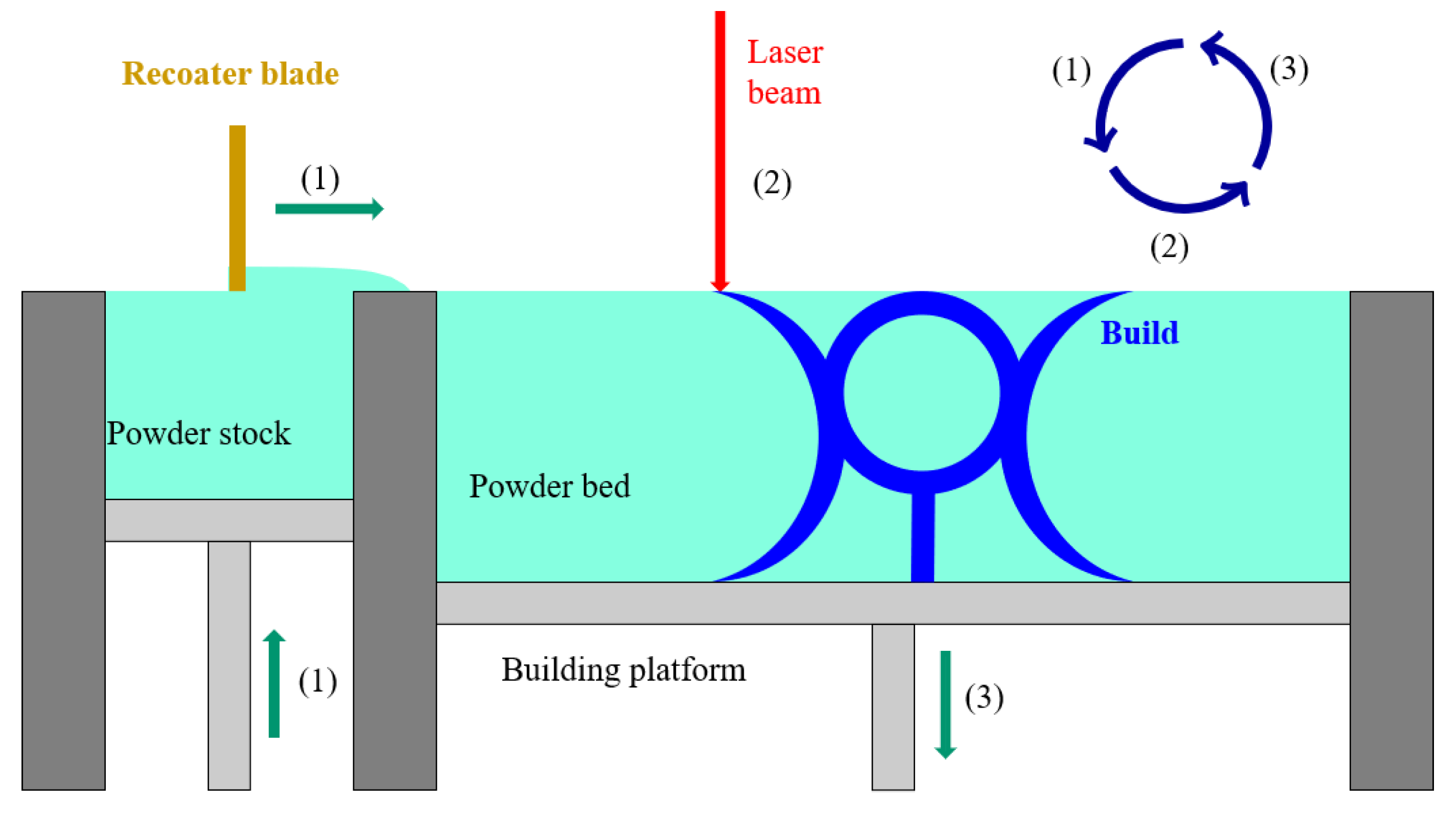
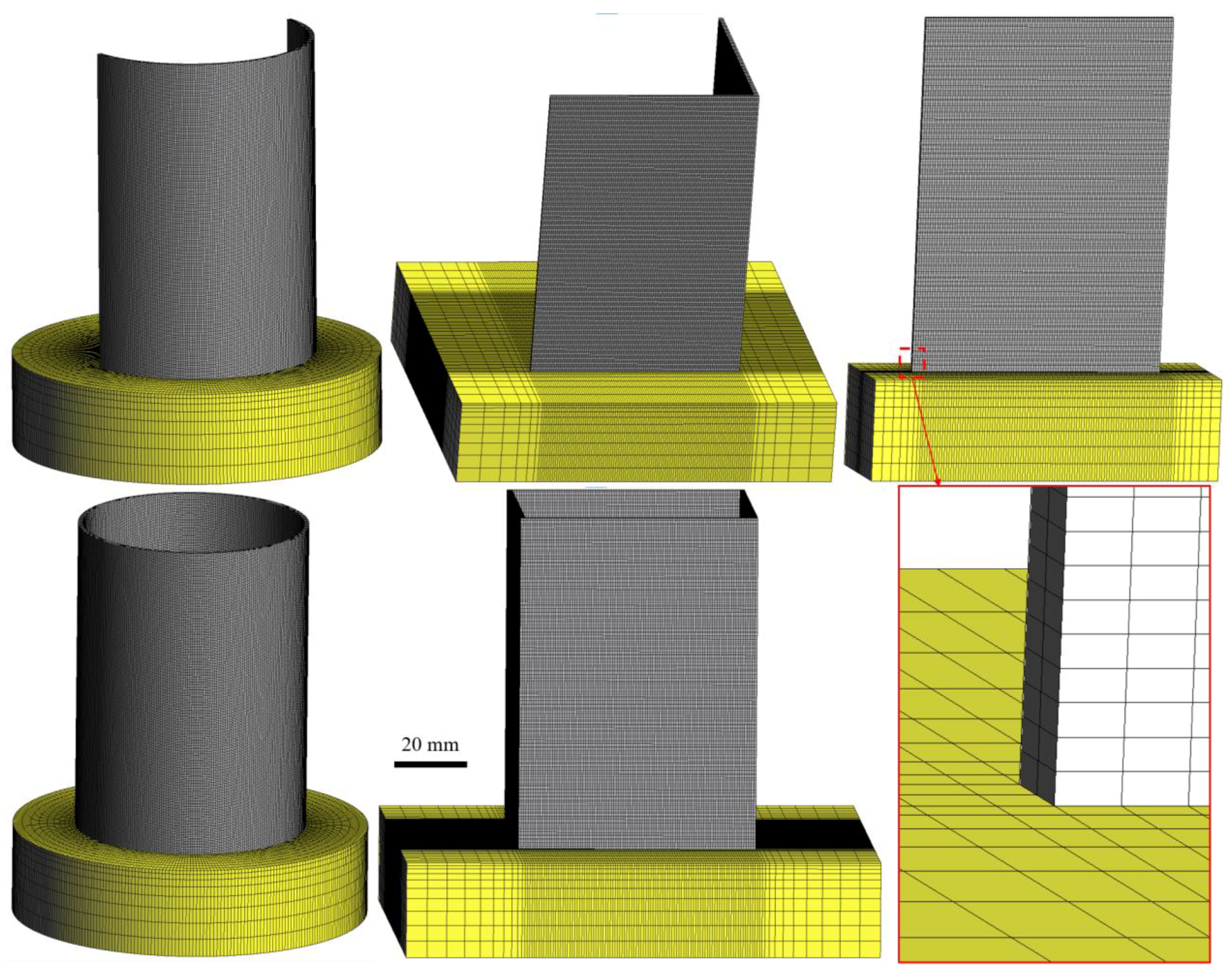
3.3. Computational Modeling of SLM

In this work, a time-marching scheme is used to simulate the SLM process. The heat source moves step-by-step from the location at time t n to the next position at time t n + 1 . During this time step, Δ t = t n + 1 t n , a heat source is applied to the affected elements. The birth-death-element technique is adopted to activate the corresponding elements belonging to each layer, according to the actual building sequence defined by the slicing tool (e.g., Cura). Both the SLM machine and the software read the same input file defined in Common Layer Interface (CLI) or g-code formats [45].
Figure 3 shows the FE meshes of five different thin-walled structures characterized by the same wall thickness of 1.0 mm. The numbers of hexahedral elements and nodes used for these geometries are listed in Table 2.
In order to reduce the computational cost while preserving the simulation precision, 10 physical layers are lumped into one with an equivalent height of 0.4 mm [46]. The meshes generated have a fixed size of approximately 0.5 × 0.5 × 0.2 mm3 for the built parts, while a coarser mesh is utilized for the base plate [47].

3.4. Material Properties and Boundary Conditions

Temperature-dependent Ti6Al4V material properties used for both the printed parts and the substrate are shown in Table 3 [38]. The environment temperature is set to 23 °C during the whole SLM process. The loose powder surrounding the SLM parts is not included in the computational domain, and an equivalent boundary condition (HTC = 5 W/(m2·°C) is used to consider its effect [34]. The heat loss at the top surface of the last printed layer is defined by a heat convection coefficient of 12.7 W/(°C·m2) and an emissivity of 0.7 [48]. The laser efficiency during the SLM process of Ti6Al4V is set to η = 0.4 [1]. An initial temperature of 23 °C is set for the new elements in the building layers. The bottom surface of the substrates is fixed as in the actual SLM machine.

3.5. Modeling of the Recoater Action

In the deposition process, contact between the recoater and the component happens when the warpages of the printed thin-walled structure reach the threshold of the used SLM machine (≈40 μm). In this instance, the friction force between the recoater and the part acts on the top surface of the newly deposited layer. The accumulated effect of this lateral force increases as both the height of the part and its warpages increase. Therefore, the effect of the recoater force is similar to that of the vertical gravity load of the deposited material.
In this work, the recoater action is modeled as an external volumetric load in the direction of the recoater blade (Y-axis), gradually applied to the growing structures with continuous layer-by-layer element activation in the mechanical simulations. Specifically, a lateral Y-directional volumetric force of 2.2 × 10⁻³ N/mm3 is applied to the newly activated elements according to the model calibration against the experimental measurements.

4. Results and Discussion

In this section, the warpage and build failures of three types of lightweight geometries with increasing structural stiffness are investigated and discussed: (i) single-wall structures; (ii) open structures; and (iii) closed geometries, as shown in Figure 4. The corresponding geometrical dimensions are shown in Table 4. Note that the actual height of the printed components does not reach the nominal value and a rough top surface for all the thin-walled structures appears. This is due to the contact between the recoater blade and the top surface of the builds during the powder spreading process in the final stage of the AM process [27]. If the contact occurs when the solidified material is still hot and deformable, proceeding with the building process can lead the recoater blade to crash [10].
To calibrate the thermo-mechanical FE model for the SLM process, the predicted part warpages are compared to the measured displacements (by 3D-scanner) with respect to the nominal CAD geometries.

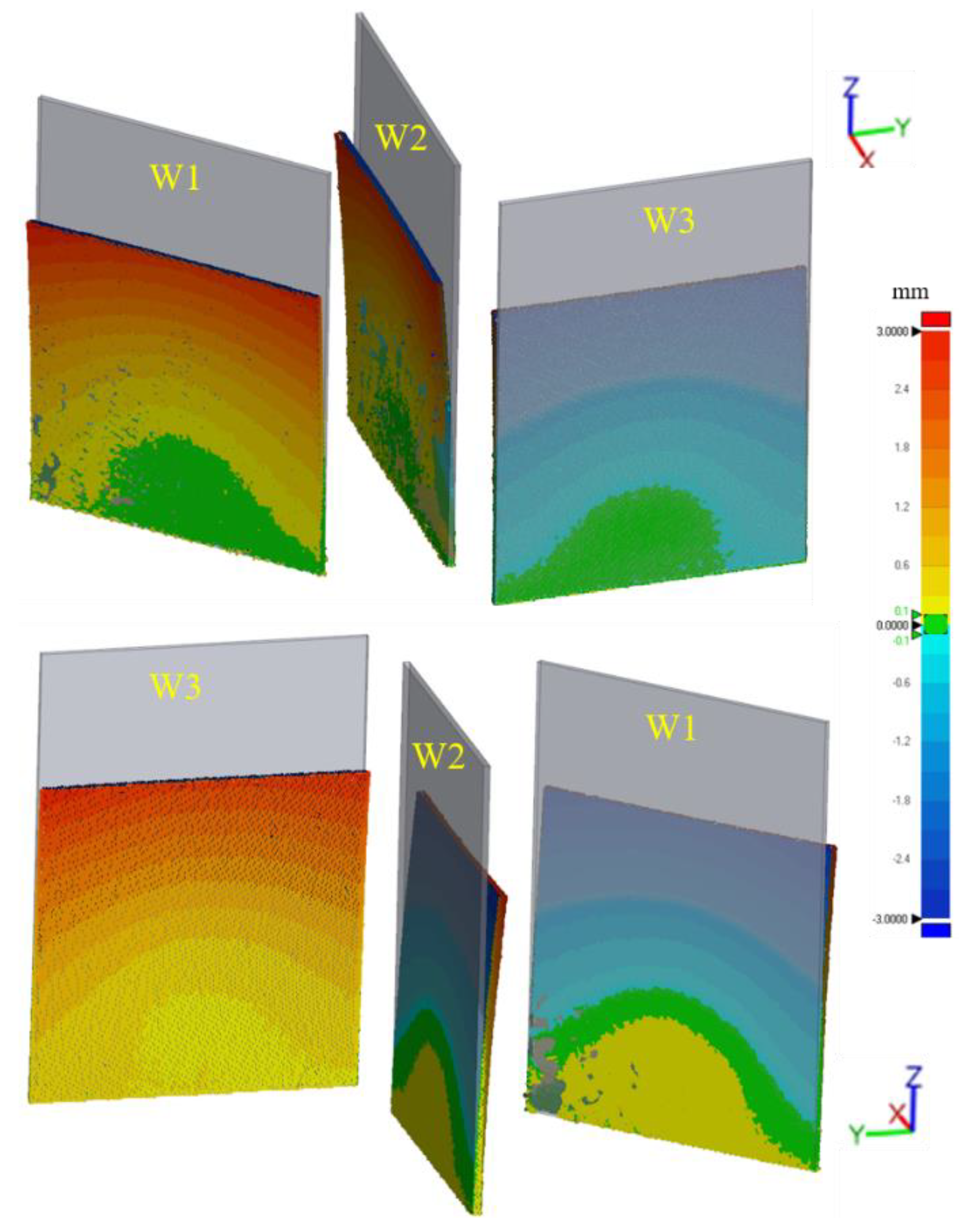
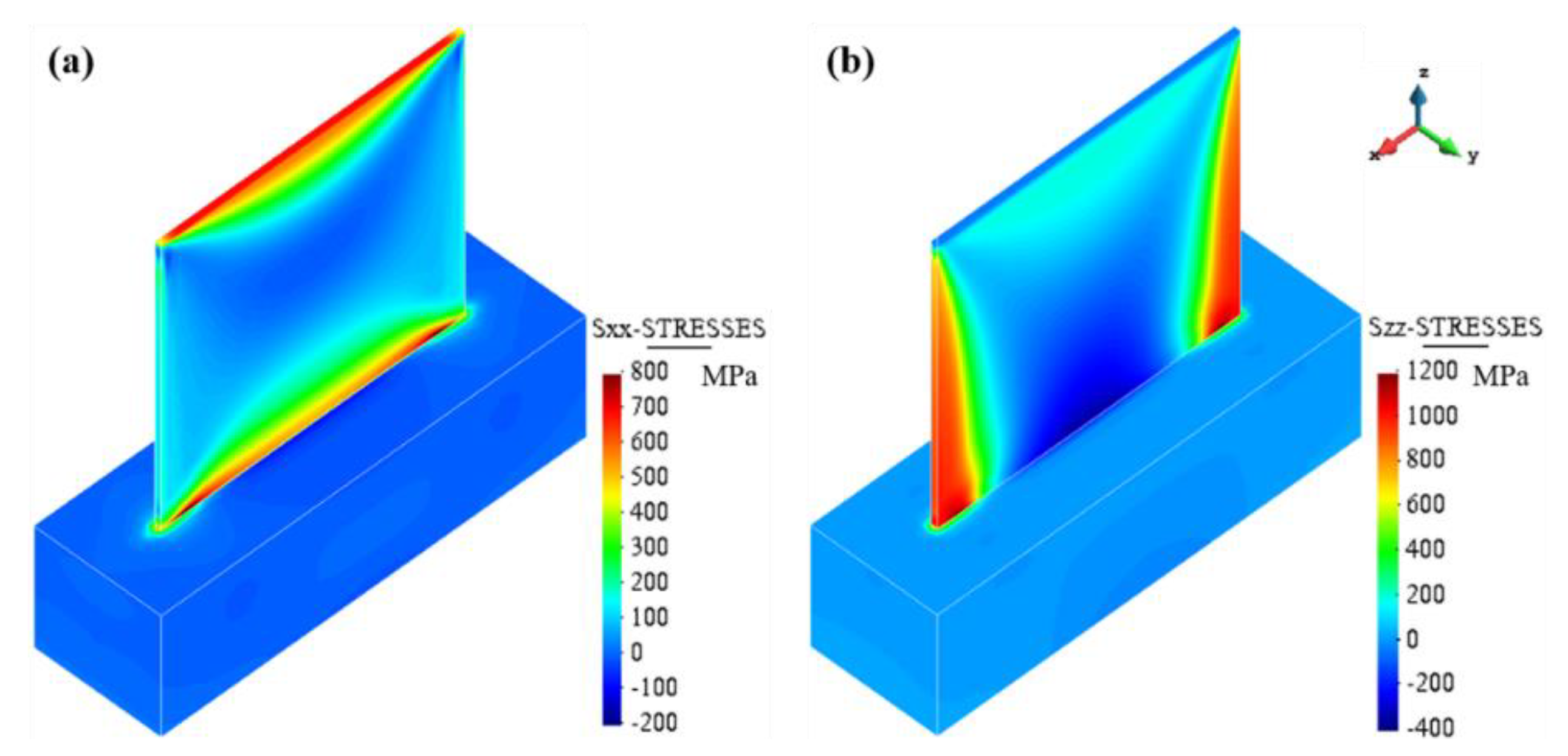
4.1. Single-Wall Structures

Figure 5 shows the uncompleted build of 3 single-wall parts and the corresponding nominal CAD geometries. Note that large distortions, up to 3 mm, are measured at the top surface of the builds. The lower section of the walls deforms in the recoating direction while the upper part is opposite to it. This depends on the induced thermal stresses and the interaction with the recoating system. Hereby, the residual longitudinal (σxx) and vertical (σzz) stresses are shown in Figure 6. It can be seen that high tensile stresses are generated at the top and the bottom layers as well as at both lateral edges, while the central area of the single-wall presents compressive stresses. This leads to the buckling of the thin-walls when any out-of-plane load such as the recoating process is applied.
Tensile stresses appear when the first layers are printed on the thick and cold substrate which induces a strong mechanical constraint. Similarly, at the top surface as well as at the edges of the wall, high thermal gradients (up to 1 × 10⁷ °C/m) are induced and the faster cooling at these locations results in large tensile stresses [1]. These residual stresses induce the warpage of thin-walled structures because of their poor structural stiffness. A similar phenomenon has been previously reported through numerical studies in references [10,37].

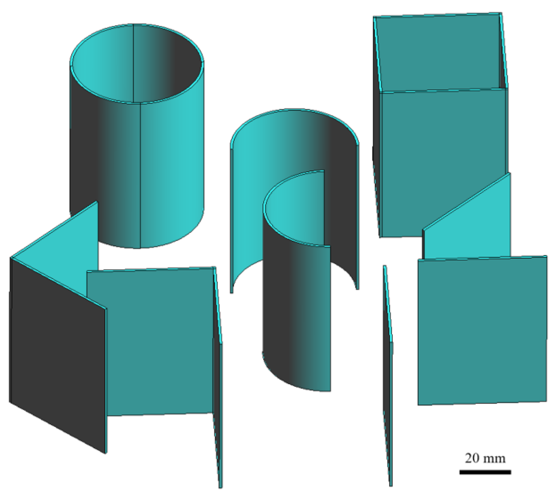
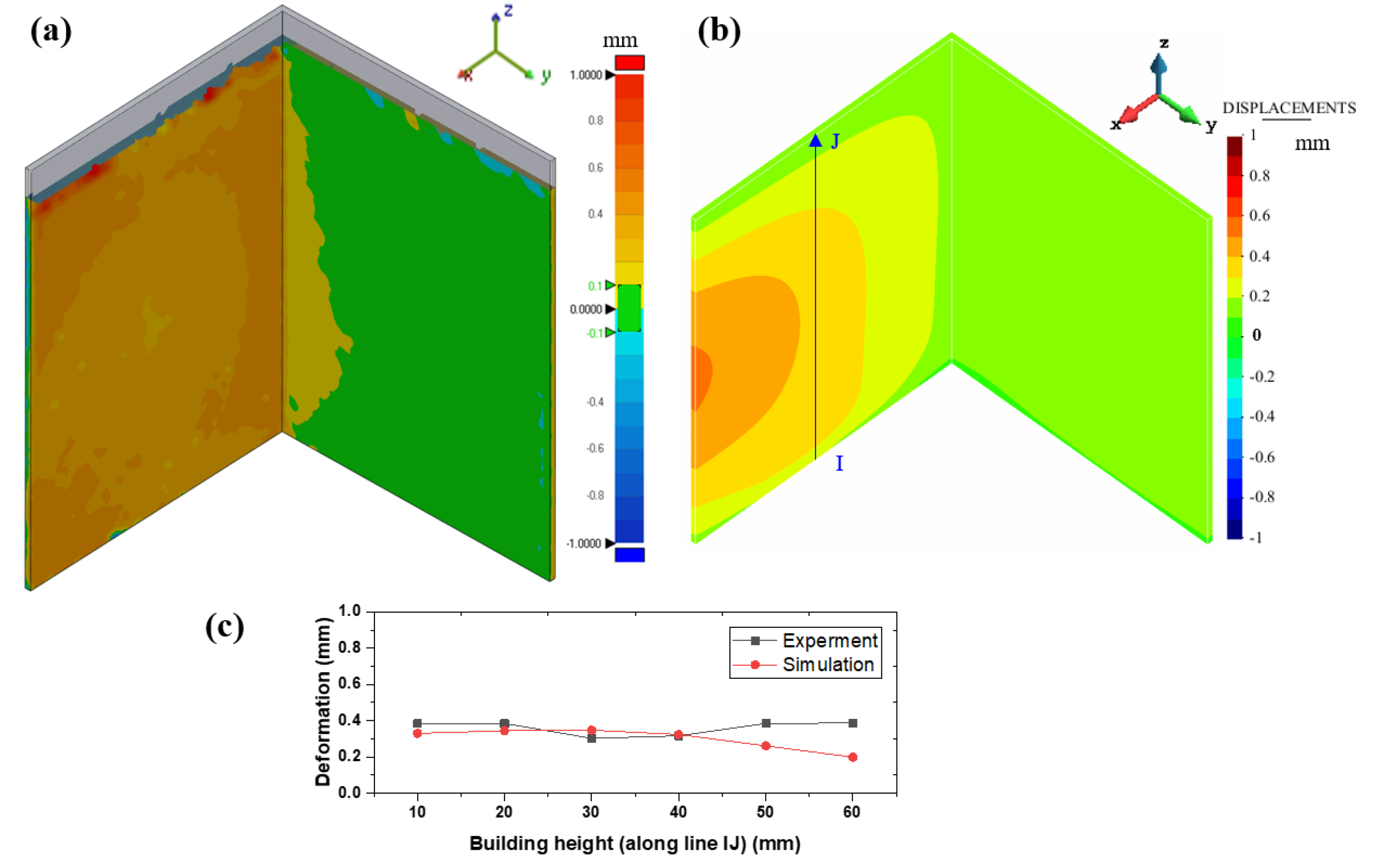
4.2. Open Thin-Walled Structures

The 3D-printing of two different open structures (semi-cylindrical and L-shape parts) is investigated in this section. Figure 7 and Figure 8 show the displacement distributions of two semi-cylindrical parts (SC1 and SC2) with different orientations with respect to the recoating system, as shown in Figure 4. The predicted warpage profiles are in good agreement with the experimental results.
It can be seen from Figure 7 that large displacements (up to 0.4 mm) are produced in the central region of the SC1 sample. The observed bulging is due to the residual stresses induced by the SLM fabrication process. Similar to the single-wall parts, these open semi-cylindrical geometries suffer of high tensile stresses along the top and bottom circumferential sides as well as at both vertical edges. As shown in Figure 9, the external surface of the inner region is characterized by tensile stresses, while the inner surface is compressed. This produces the bulging, as also reported in [49,50].
The bulging also induces vertical displacements which interfere with the powder spreading by the recoating system. As a consequence, the top surface presents a roughness deteriorating the printing job until, eventually, the recoater crashes. This interference also provokes the appearance of forces typically in the recoater advancing Y-direction, and, consequently, forcing bending in this direction (see Figure 7a).
Similar considerations apply for the semi-cylindrical (SC2) structure, as shown in Figure 8. In this case, the bulging is even more pronounced (approximately 0.5 mm).
The comparison between the predicted and measured out-of-plane displacements of the two L-shape parts, namely the L1 and L2 samples, is shown in Figure 10 and Figure 11, respectively.
The difference in the manufacturing process between these two thin-walled structures is due to their orientations with respect to the recoating movement. In particular, sample L2 has one of the two walls parallel to the movement of the recoater (see Figure 4). Thus, its structural stiffness to the recoater loading is higher than the one of sample L1. This can be easily appreciated when comparing the warpages of L1 and L2 and keeping in mind that the recoater loading is in the Y-direction.
Figure 12 shows the residual stresses for the two L-shaped parts. The stress distributions are similar for both cases, mainly depending on the thermal deformations during the printing process. As for the single-wall builds, the L-shaped structures present high tensile stresses at the external edges as well as at the top and bottom layers. At the sharp corner, a similar vertical stress concentration can also be appreciated. Similar stress results can be found in [51,52]. This stress field is responsible for the pronounced double buckling shown in Figure 10 and Figure 11.

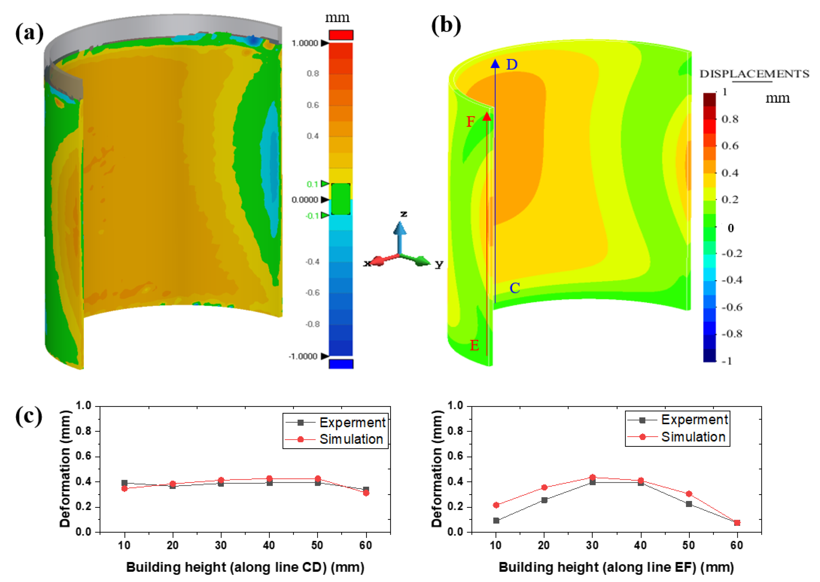
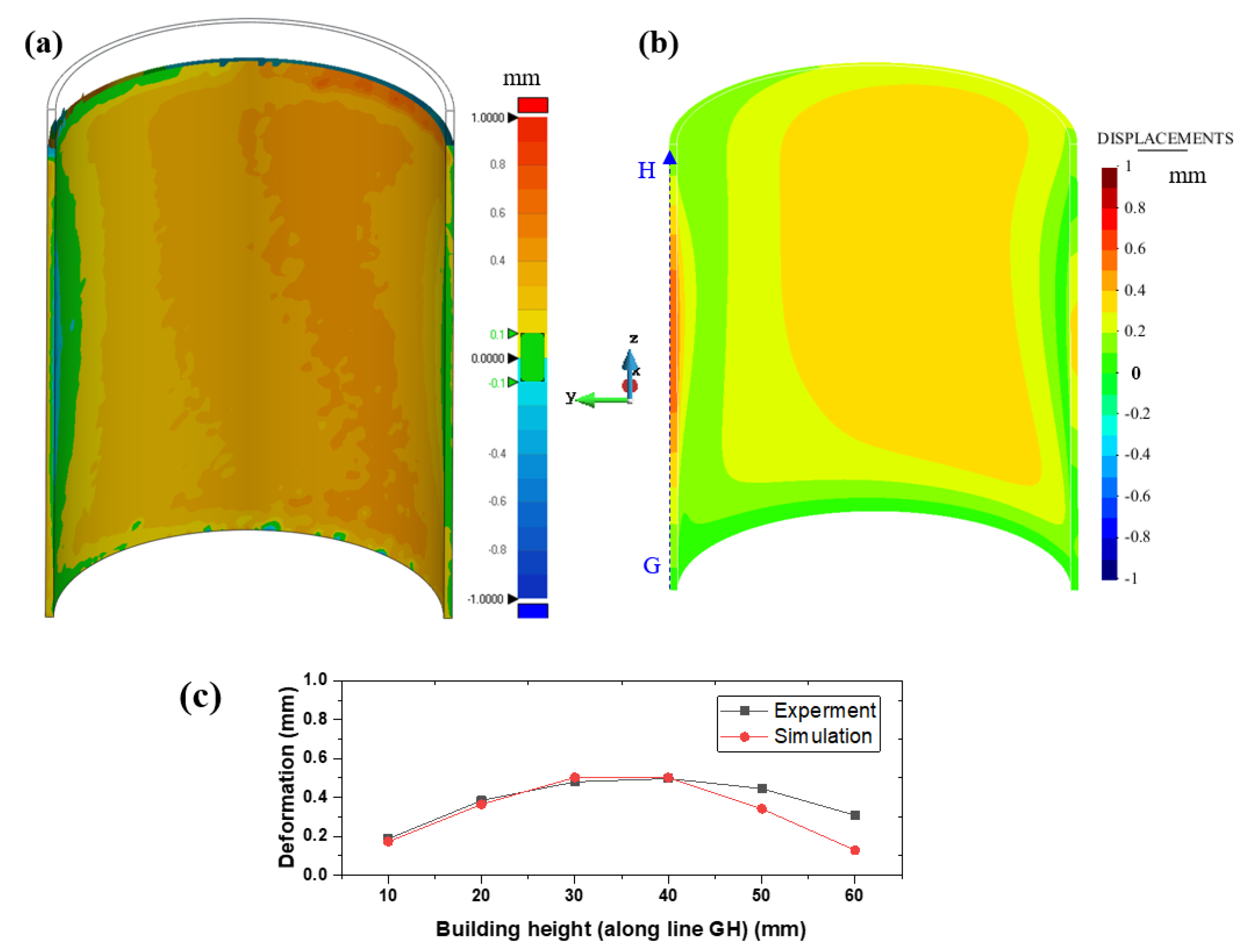
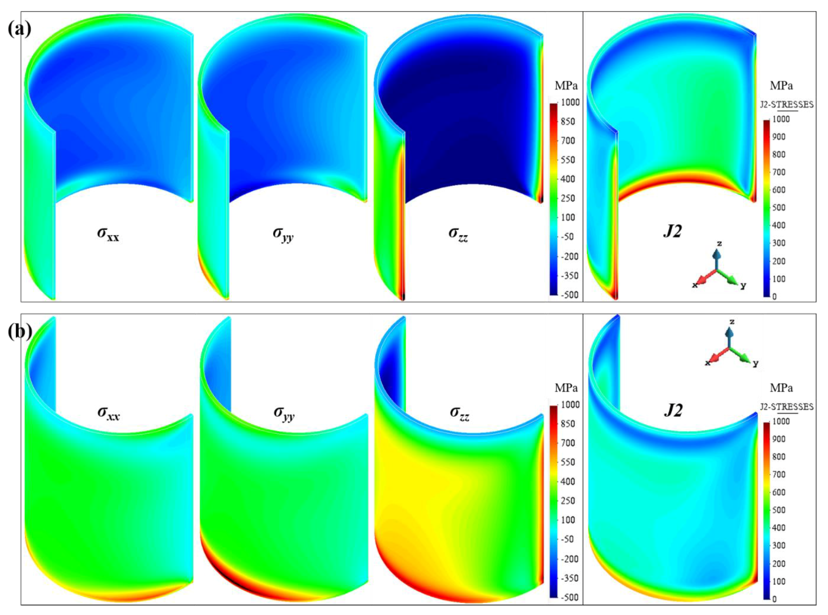
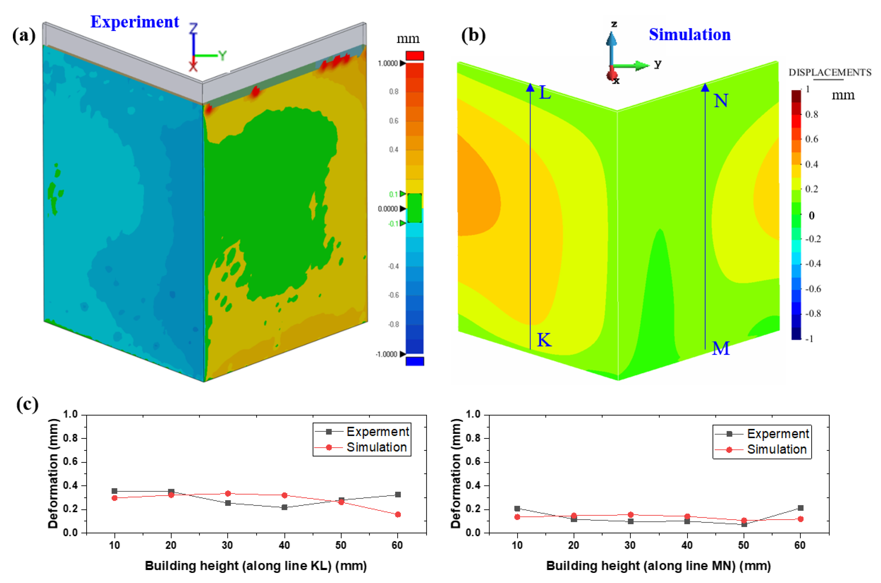
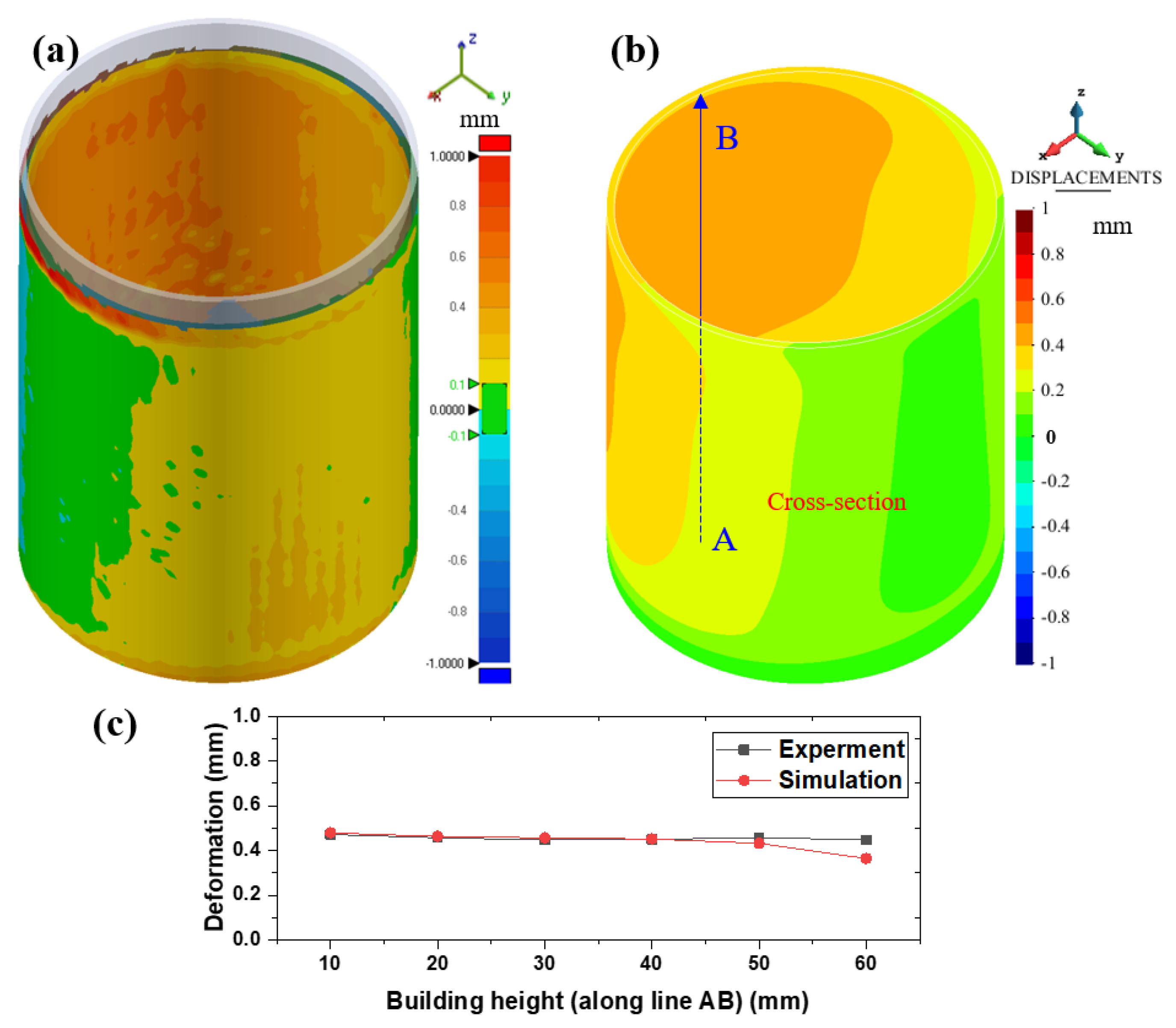
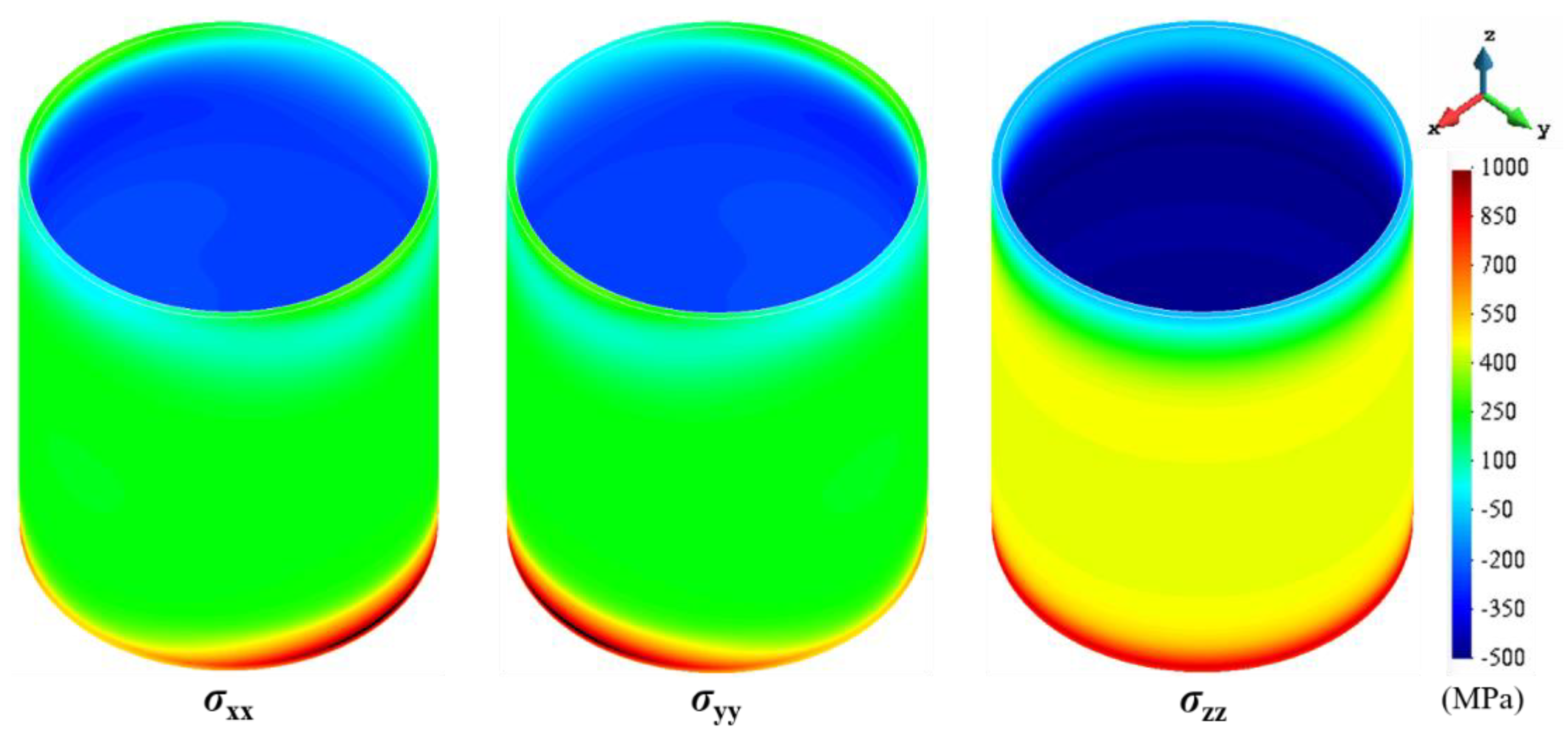
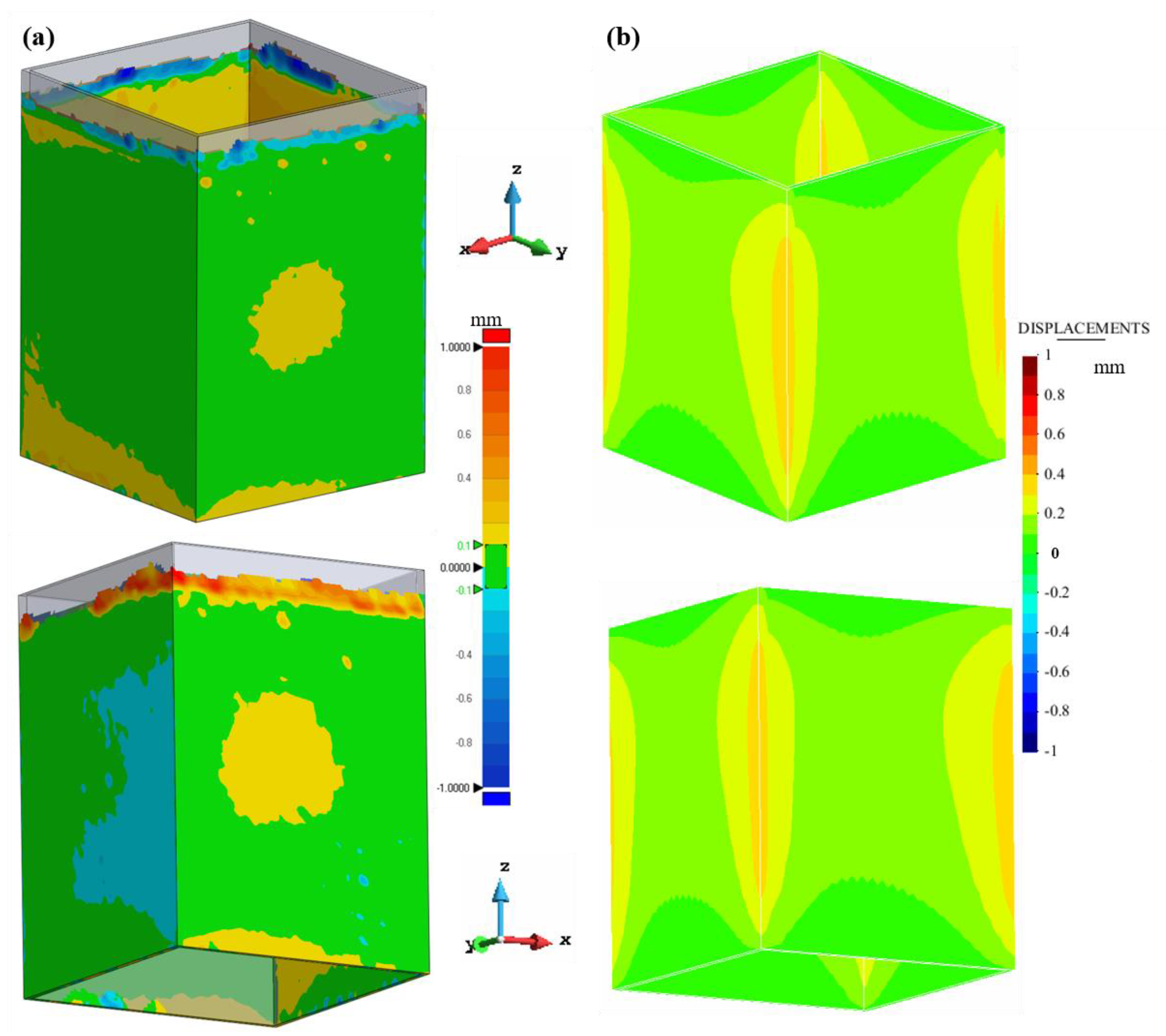
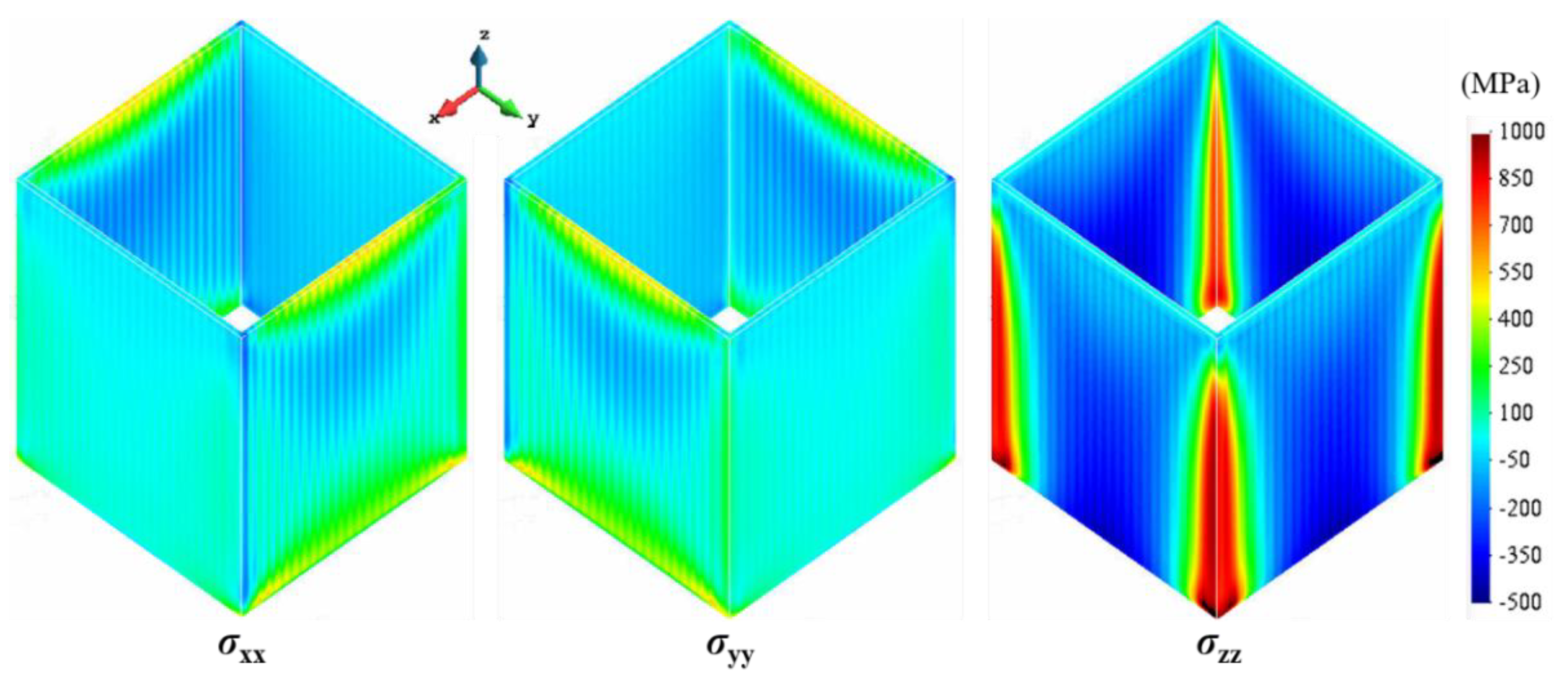
4.3. Closed Thin-Walled Structures

In this section, the mechanical behavior of two closed structures, the hollow cylindrical and square geometries, is studied to assess the influence of recoater interference during the SLM process.
Figure 13 compares the simulated displacement distributions and the experimental 3D-scan measurements for the cylindrical part. Figure 14 shows the corresponding residual stress field. Note that compressive stresses are produced on the inner surface of the cylinder while its external surface suffers tensile stresses. Thus, the cylinder contracts in the radial direction during the cooling process, and relatively small radial displacements are generated due to the higher structural stiffness of closed geometries compared to the open ones [53,54]. However, also in this case, a large Y-displacement, up to 0.5 mm, can be appreciated (Figure 13). Moreover, the build is uncompleted due to the collision between the scraper and the distorted part.
Similar considerations apply for the hollow square part in terms of both warpage (see Figure 15) and stress distributions (see Figure 16). The higher stiffness of this geometry compared to the single-wall or the L-shape structures implies a smaller distortion of the build. However, in Figure 15a, the same bulging phenomenon can be appreciated, being more pronounced in the surfaces orthogonal to the recoating direction.

5. Proposed Strategies to Reduce the Warpage of Thin-Walled Structures

This numerical study demonstrates that the residual stresses generated by the AM fabrication process can lead to large distortions and buckling phenomena, particularly when thin-walled structures are printed. The structural stiffness of the geometry is one of the key factors to mitigate the final warpage of the builds. A possible strategy to mitigate the distortions during the AM process is the component integration, as shown in Figure 17. This implies that the manufacturing process must include two stages: (i) 3D printing and (ii) separation of parts (e.g., cutting). The effectiveness of this procedure is evident for the geometries investigated in this work. However, more complex geometries can be placed on the base platform, keeping in mind these results; different components to be printed could share some of the surfaces, edges, etc.
The benefits of component integration not only include increased global stiffness of the thin-walled structures but also an improved temperature field. In fact, the stress concentration at the lateral edges is due to their faster cooling. Thus, agglomerating the parts and integrating them by sharing some of the geometrical features (edges, surfaces, etc.) can produce a more uniform temperature field. Thus, the temperature gradients responsible for the thermal stress concentrations can be effectively mitigated.
Geometry compensation is another possibility to guarantee the geometrical precision of thin-walled lightweight structures fabricated by SLM [55,56]. This is an inverse engineering strategy used to modify the nominal CAD geometry considering the part warpage predicted by the numerical simulation to iteratively compensate the initial CAD model.
Figure 18 demonstrates the effectiveness of using geometric compensation after one iteration. Observe that high residual stresses still persist. However, these can be addressed through post annealing treatment.
Finally, using a softer scraper in the current SLM machine would also be beneficial for reducing part deformations and damages to the recoating system.

6. Conclusions

In this work, the 3D-printing of different lightweight geometries of Ti6Al4V is investigated. In-house FE thermo-mechanical software has been enhanced to consider the recoating effects. The numerical framework has been calibrated using the experimental results obtained by a 3D scanner. The following validation has demonstrated good agreement between the simulated displacements and the experimental measurements of different thin-walled structures. Finally, the validated model is used to analyze the residual stress evolution during the whole printing process.
The major conclusions of this study are the following:
  • The recoating system affects the residual warpage of the build. Thus, the orientation of the part on the build-plate with respect to the recoating direction makes a difference. This effect is more pronounced when open structures are considered. The higher structural stiffness of the closed-structures mitigates this phenomenon.
  • The vertical displacements at the top surface of the build are amplified by the bulging phenomenon shown by these kinds of structures. The interference between the recoating system and the roughness generated by the non-uniform powder bed spreading generates increased loading in the direction of the recoater’s movement. The induced bending is more pronounced when these loads are orthogonal to the thin surfaces. Thus, the orientation of the lightweight structures on the base platform is relevant.
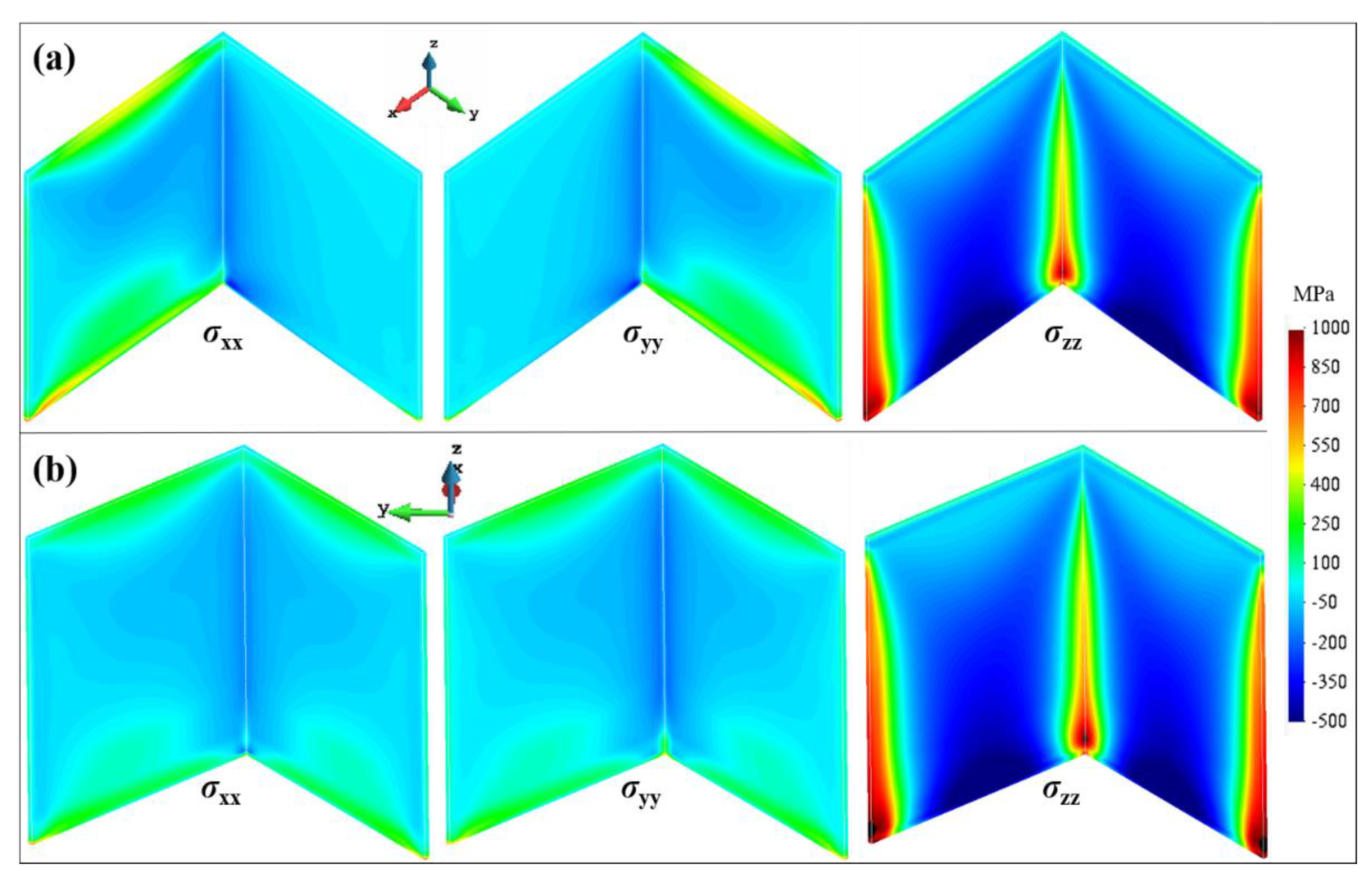
  • Open lightweight structures are more prone to warpage due to their reduced structural stiffness compared to closed ones. However, higher residual stresses appear on the latter and can be relaxed through post-annealing treatment. Therefore, component integration is a possible solution to increase the overall stiffness of the build to better resist the thermal stresses induced by the fabrication process as well as generate a more uniform temperature field, thus lowering temperature gradients and stress concentrations.
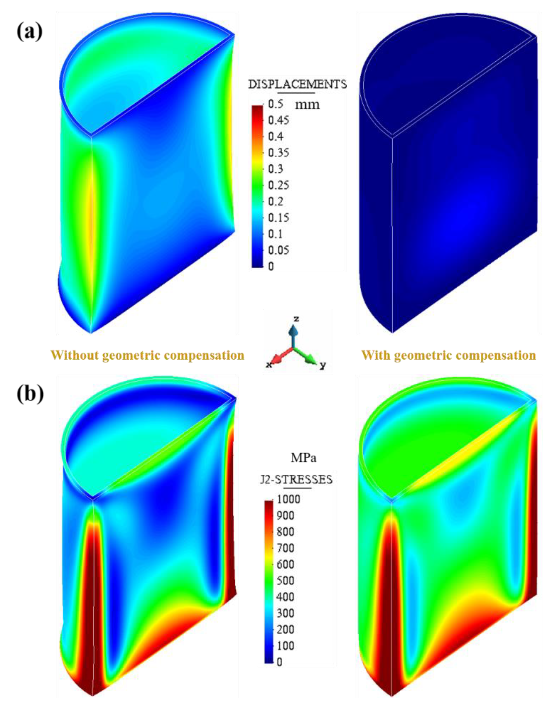
  • Geometry compensation is a good inverse engineering strategy to modify the original nominal geometry, accounting for the part warpage due to the AM process and ensuring optimal geometrical accuracy in SLM-parts.

Author Contributions

Conceptualization, X.L. and M.C. (Michele Chiumenti); methodology, I.G.; software, M.C. (Miguel Cervera); validation, M.S.; investigation, X.L.; data curation, M.S.; writing—original draft preparation, X.L.; writing—review and editing, M.C. (Miguel Cervera); supervision, M.C. (Michele Chiumenti) and M.C. (Miguel Cervera); project administration, M.C. (Michele Chiumenti). All authors have read and agreed to the published version of the manuscript.

Funding

This research was funded by the Spanish Ministry of Economy and Competitiveness, through the Severo Ochoa Programme for Centers of Excellence in R&D (CEX2018-000797-S). This work has been supported by the Ministry of Science, Innovation and Universities (MCIU), Spain via the PriMuS project (Printing pattern based and MultiScale enhanced performance analysis of advanced Additive Manufacturing components, No. PID2020-115575RB-I00) and by the Light3D project (No. 001-P-001646) as part of the BASE3D network by ACCIÓ (Generalitat de Catalunya). The support from the China Scholarship Council (No. 201906290011) is also gratefully acknowledged.

Data Availability Statement

Not applicable.

Conflicts of Interest

The authors declare no conflict of interest.

References

  1. Lu, X.; Zhang, W.; Chiumenti, M.; Cervera, M.; Gillham, B.; Yu, P.; Yin, S.; Lin, X.; Babu, R.P.; Lupoi, R. Crack-free laser powder bed fusion by substrate design. Addit. Manuf. 2022, 59, 103149. [Google Scholar] [CrossRef]
  2. Pérez-Ruiz, J.D.; de Lacalle, L.N.L.; Urbikain, G.; Pereira, O.; Martínez, S.; Bris, J. On the relationship between cutting forces and anisotropy features in the milling of LPBF Inconel 718 for near net shape parts. Int. J. Mach. Tools Manuf. 2021, 170, 103801. [Google Scholar] [CrossRef]
  3. Plocher, J.; Panesar, A. Review on design and structural optimisation in additive manufacturing: Towards next-generation lightweight structures. Mater. Des. 2019, 183, 108164. [Google Scholar] [CrossRef]
  4. Pérez-Ruiz, J.D.; Marin, F.; Martínez, S.; Lamikiz, A.; Urbikain, G.; de Lacalle, L.N.L. Stiffening near-net-shape functional parts of Inconel 718 LPBF considering material anisotropy and subsequent machining issues. Mech. Syst. Signal Process. 2022, 168, 108675. [Google Scholar] [CrossRef]
  5. Lu, X.; Zhao, T.; Ji, X.; Hu, J.; Li, T.; Lin, X.; Huang, W. 3D printing well organized porous iron-nickel/polyaniline nanocages multiscale supercapacitor. J. Alloy. Compd. 2018, 760, 78–83. [Google Scholar] [CrossRef]
  6. Prasad, A.; Yuan, L.; Lee, P.; Patel, M.; Qiu, D.; Easton, M.; StJohn, D. Towards understanding grain nucleation under Additive Manufacturing solidification conditions. Acta Mater. 2020, 195, 392–403. [Google Scholar] [CrossRef]
  7. Martin, A.A.; Calta, N.P.; Khairallah, S.A.; Wang, J.; Depond, P.J.; Fong, A.Y.; Thampy, V.; Guss, G.M.; Kiss, A.M.; Stone, K.H.; et al. Dynamics of pore formation during laser powder bed fusion additive manufacturing. Nat. Commun. 2019, 10, 1987. [Google Scholar] [CrossRef] [PubMed] [Green Version]
  8. Hooper, P.A. Melt pool temperature and cooling rates in laser powder bed fusion. Addit. Manuf. 2018, 22, 548–559. [Google Scholar] [CrossRef]
  9. Diegel, O.; Nordin, A.; Motte, D. A Practical Guide to Design for Additive Manufacturing; Springer: Singapore, 2019. [Google Scholar]
  10. Chakraborty, A.; Tangestani, R.; Batmaz, R.; Muhammad, W.; Plamondon, P.; Wessman, A.; Yuan, L.; Martin, É. In-process failure analysis of thin-wall structures made by laser powder bed fusion additive manufacturing. J. Mater. Sci. Technol. 2021, 98, 233–243. [Google Scholar] [CrossRef]
  11. Cheng, L.; Liang, X.; Bai, J.; Chen, Q.; Lemon, J.; To, A. On utilizing topology optimization to design support structure to prevent residual stress induced build failure in laser powder bed metal additive manufacturing. Addit. Manuf. 2019, 27, 290–304. [Google Scholar] [CrossRef]
  12. Lu, X.; Zhang, G.; Li, J.; Cervera, M.; Chiumenti, M.; Chen, J.; Lin, X.; Huang, W. Simulation-assisted investigation on the formation of layer bands and the microstructural evolution in directed energy deposition of Ti6Al4V blocks. Virtual Phys. Prototyp. 2021, 16, 387–403. [Google Scholar] [CrossRef]
  13. Megahed, M.; Mindt, H.-W.; N’Dri, N.; Duan, H.; Desmaison, O. Metal additive-manufacturing process and residual stress modeling. Integr. Mater. Manuf. Innov. 2016, 5, 61–93. [Google Scholar] [CrossRef] [Green Version]
  14. Uhlmann, E.; Kersting, R.; Klein, T.B.; Cruz, M.F.; Borille, A.V. Additive Manufacturing of Titanium Alloy for Aircraft Components. Procedia CIRP 2015, 35, 55–60. [Google Scholar] [CrossRef]
  15. Wu, Z.; Narra, S.P.; Rollett, A. Exploring the fabrication limits of thin-wall structures in a laser powder bed fusion process. Int. J. Adv. Manuf. Technol. 2020, 110, 191–207. [Google Scholar] [CrossRef]
  16. Thompson, S.M.; Aspin, Z.S.; Shamsaei, N.; Elwany, A.; Bian, L. Additive manufacturing of heat exchangers: A case study on a multi-layered Ti–6Al–4V oscillating heat pipe. Addit. Manuf. 2015, 8, 163–174. [Google Scholar] [CrossRef]
  17. Kilian, M.; Hartwanger, C.; Schneider, M.; Hatzenbichler, M. Waveguide components for space applications manufactured by additive manufacturing technology. IET Microw. Antennas Propag. 2017, 11, 1949–1954. [Google Scholar] [CrossRef]
  18. Calleja-Ochoa, A.; Gonzalez-Barrio, H.; López de Lacalle, N.; Martínez, S.; Albizuri, J.; Lamikiz, A. A new approach in the design of microstructured ultralight components to achieve maximum functional performance. Materials 2021, 14, 1588. [Google Scholar] [CrossRef]
  19. Pascual, A.; Ortega, N.; Plaza, S.; de Lacalle, L.N.L.; Ukar, E. Analysis of the influence of L-PBF porosity on the mechanical behavior of AlSi10Mg by XRCT-based FEM. J. Mater. Res. Technol. 2023, 22, 958–981. [Google Scholar] [CrossRef]
  20. Yavari, R.; Smoqi, Z.; Riensche, A.; Bevans, B.; Kobir, H.; Mendoza, H.; Song, H.; Cole, K.; Rao, P. Part-scale thermal simulation of laser powder bed fusion using graph theory: Effect of thermal history on porosity, micro-structure evolution, and recoater crash. Mater. Des. 2021, 204, 109685. [Google Scholar] [CrossRef]
  21. Kayacan, M.Y.; Özsoy, K.; Duman, B.; Yilmaz, N.; Kayacan, M.C. A study on elimination of failures resulting from layering and internal stresses in Powder Bed Fusion (PBF) additive manufacturing. Mater. Manuf. Process. 2019, 34, 1467–1475. [Google Scholar] [CrossRef]
  22. Lu, X.; Chiumenti, M.; Cervera, M.; Li, J.; Lin, X.; Ma, L.; Zhang, G.; Liang, E. Substrate design to minimize residual stresses in Directed Energy Deposition AM processes. Mater. Des. 2021, 202, 109525. [Google Scholar] [CrossRef]
  23. Zhang, W.; Tong, M.; Harrison, N.M. Resolution, energy and time dependency on layer scaling in finite element modelling of laser beam powder bed fusion additive manufacturing. Addit. Manuf. 2019, 28, 610–620. [Google Scholar] [CrossRef]
  24. Carraturo, M.; Kollmannsberger, S.; Reali, A.; Auricchio, F.; Rank, E. An immersed boundary approach for residual stress evaluation in selective laser melting processes. Addit. Manuf. 2021, 46, 102077. [Google Scholar] [CrossRef]
  25. Promoppatum, P.; Onler, R.; Yao, S.-C. Numerical and experimental investigations of micro and macro characteristics of direct metal laser sintered Ti-6Al-4V products. J. Mater. Process. Technol. 2016, 240, 262–273. [Google Scholar] [CrossRef]
  26. Wang, D.; Yang, Y.; Yi, Z.; Su, X. Research on the fabricating quality optimization of the overhanging surface in SLM process. Int. J. Adv. Manuf. Technol. 2012, 65, 1471–1484. [Google Scholar] [CrossRef]
  27. Wang, D.; Yang, Y.; Liu, R.; Xiao, D.; Sun, J. Study on the designing rules and processability of porous structure based on selective laser melting (SLM). J. Mater. Process. Technol. 2013, 213, 1734–1742. [Google Scholar] [CrossRef]
  28. Yakout, M.; Cadamuro, A.; Elbestawi, M.A.; Veldhuis, S.C. The selection of process parameters in additive manufacturing for aerospace alloys. Int. J. Adv. Manuf. Technol. 2017, 92, 2081–2098. [Google Scholar] [CrossRef]
  29. Le, T.-P.; Wang, X.; Davidson, K.P.; Fronda, J.E.; Seita, M. Experimental analysis of powder layer quality as a function of feedstock and recoating strategies. Addit. Manuf. 2021, 39, 101890. [Google Scholar] [CrossRef]
  30. Weinberg, J. A Precision Blade Mechanism for Powder Recoating in Selective Laser Melting. Master’s Thesis, Massachusetts Institute of Technology, Cambridge, MA, USA, 2018. [Google Scholar]
  31. Zhu, C.; Chen, X.; Wu, H.; Zhu, J.; Peng, T.; Lv, J.; Wu, Y. Multi-Objective Optimization of Selective Laser Melting Processes for Minimizing Energy Consumption and Maximizing Product Tensile Strength. Metals 2022, 12, 1782. [Google Scholar] [CrossRef]
  32. Chiumenti, M.; Neiva, E.; Salsi, E.; Cervera, M.; Badia, S.; Moya, J.; Chen, Z.; Lee, C.; Davies, C.; Chiumenti, M.; et al. Numerical modelling and experimental validation in Selective Laser Melting. Addit. Manuf. 2017, 18, 171–185. [Google Scholar] [CrossRef] [Green Version]
  33. Kobir, M.H.; Yavari, R.; Riensche, A.R.; Bevans, B.D.; Castro, L.; Cole, K.D.; Rao, P. Prediction of recoater crash in laser powder bed fusion additive manufacturing using graph theory thermomechanical modeling. Prog. Addit. Manuf. 2022, 1–26. [Google Scholar] [CrossRef]
  34. Cao, J.; Gharghouri, M.A.; Nash, P. Finite-element analysis and experimental validation of thermal residual stress and distortion in electron beam additive manufactured Ti-6Al-4V build plates. J. Mater. Process. Technol. 2016, 237, 409–419. [Google Scholar] [CrossRef]
  35. Vastola, G.; Sin, W.; Sun, C.-N.; Sridhar, N. Design guidelines for suppressing distortion and buckling in metallic thin-wall structures built by powder-bed fusion additive manufacturing. Mater. Des. 2022, 215, 110489. [Google Scholar] [CrossRef]
  36. Li, Z.; Xu, R.; Zhang, Z.; Kucukkoc, I. The influence of scan length on fabricating thin-walled components in selective laser melting. Int. J. Mach. Tools Manuf. 2018, 126, 1–12. [Google Scholar] [CrossRef]
  37. Chen, C.; Xiao, Z.; Zhu, H.; Zeng, X. Deformation and control method of thin-walled part during laser powder bed fusion of Ti–6Al–4V alloy. Int. J. Adv. Manuf. Technol. 2020, 110, 3467–3478. [Google Scholar] [CrossRef]
  38. Lu, X.; Lin, X.; Chiumenti, M.; Cervera, M.; Li, J.; Ma, L.; Wei, L.; Hu, Y.L.; Huang, W. Finite element analysis and experimental validation of the thermomechanical behavior in laser solid forming of Ti-6Al-4V. Addit. Manuf. 2018, 21, 30–40. [Google Scholar] [CrossRef]
  39. Chiumenti, M.; Cervera, M.; Salmi, A.; de Saracibar, C.A.; Dialami, N.; Matsui, K. Finite element modeling of multi-pass welding and shaped metal deposition processes. Comput. Methods Appl. Mech. Eng. 2010, 199, 2343–2359. [Google Scholar] [CrossRef]
  40. Lu, X.; Chiumenti, M.; Cervera, M.; Zhang, G.; Lin, X. Mitigation of residual stresses and microstructure homogenization in directed energy deposition processes. Eng. Comput. 2022, 38, 4771–4790. [Google Scholar] [CrossRef]
  41. Lu, X.; Lin, X.; Chiumenti, M.; Cervera, M.; Hu, Y.; Ji, X.; Ma, L.; Huang, W. In situ measurements and thermo-mechanical simulation of Ti–6Al–4V laser solid forming processes. Int. J. Mech. Sci. 2019, 153, 119–130. [Google Scholar] [CrossRef]
  42. Denlinger, E.R.; Michaleris, P. Effect of stress relaxation on distortion in additive manufacturing process modeling. Addit. Manuf. 2016, 12, 51–59. [Google Scholar] [CrossRef] [Green Version]
  43. Chen, Z.; Ye, H.; Xu, H. Distortion control in a wire-fed electron-beam thin-walled Ti-6Al-4V freeform. J. Mater. Process. Technol. 2018, 258, 286–295. [Google Scholar] [CrossRef]
  44. Chiumenti, M.; Cervera, M.; de Saracibar, C.A.; Dialami, N. Numerical modeling of friction stir welding processes. Comput. Methods Appl. Mech. Eng. 2013, 254, 353–369. [Google Scholar] [CrossRef]
  45. Moreira, C.A.; Caicedo, M.A.; Cervera, M.; Chiumenti, M.; Baiges, J. A multi-criteria h-adaptive finite-element framework for industrial part-scale thermal analysis in additive manufacturing processes. Eng. Comput. 2022, 38, 4791–4813. [Google Scholar] [CrossRef]
  46. Li, C.; Liu, Z.Y.; Fang, X.Y.; Guo, Y.B. On the Simulation Scalability of Predicting Residual Stress and Distortion in Selective Laser Melting. J. Manuf. Sci. Eng. 2018, 140, 041013. [Google Scholar] [CrossRef]
  47. Chiumenti, M.; Cervera, M.; Dialami, N.; Wu, B.; Jinwei, L.; de Saracibar, C.A. Numerical modeling of the electron beam welding and its experimental validation. Finite Elem. Anal. Des. 2016, 121, 118–133. [Google Scholar] [CrossRef] [Green Version]
  48. Zhang, W.; Tong, M.; Harrison, N.M. Multipart Build Effects on Temperature and Residual Stress by Laser Beam Powder Bed Fusion Additive Manufacturing. 3D Print. Addit. Manuf. 2021. [Google Scholar] [CrossRef]
  49. Abarca, M.J.; Darabi, R.; de Sa, J.C.; Parente, M.; Reis, A. Multi-scale modeling for prediction of residual stress and distortion in Ti–6Al–4V semi-circular thin-walled parts additively manufactured by laser powder bed fusion (LPBF). Thin-Walled Struct. 2023, 182, 110151. [Google Scholar] [CrossRef]
  50. Biegler, M.; Elsner, B.A.; Graf, B.; Rethmeier, M. Geometric distortion-compensation via transient numerical simulation for directed energy deposition additive manufac-turing. Sci. Technol. Weld. Join. 2020, 25, 468–475. [Google Scholar] [CrossRef]
  51. Hajializadeh, F.; Ince, A. Integration of artificial neural network with finite element analysis for residual stress prediction of direct metal deposition process. Mater. Today Commun. 2021, 27, 102197. [Google Scholar] [CrossRef]
  52. Yang, T.; Xie, D.; Yue, W.; Wang, S.; Rong, P.; Shen, L.; Zhao, J.; Wang, C. Distortion of Thin-Walled Structure Fabricated by Selective Laser Melting Based on Assumption of Constraining Force-Induced Distortion. Metals 2019, 9, 1281. [Google Scholar] [CrossRef] [Green Version]
  53. Dunbar, A.J. Analysis of the Laser Powder Bed Fusion Additive Manufacturing Process through Experimental Measurement and Finite Element Modeling; The Pennsylvania State University: State College, PA, USA, 2016. [Google Scholar]
  54. He, P.; Sun, C.; Wang, Y. Material distortion in laser-based additive manufacturing of fuel cell component: Three-dimensional numerical analysis. Addit. Manuf. 2021, 46, 102188. [Google Scholar] [CrossRef]
  55. Afazov, S.; Semerdzhieva, E.; Scrimieri, D.; Serjouei, A.; Kairoshev, B.; Derguti, F. An improved distortion compensation approach for additive manufacturing using optically scanned data. Virtual Phys. Prototyp. 2021, 16, 1–13. [Google Scholar] [CrossRef]
  56. Hartmann, C.; Lechner, P.; Himmel, B.; Krieger, Y.; Lueth, T.C.; Volk, W. Compensation for Geometrical Deviations in Additive Manufacturing. Technologies 2019, 7, 83. [Google Scholar] [CrossRef] [Green Version]
Figure 1. Schematic drawing of the workflow of the typical SLM process where the part shape is not fixed.
Jmmp 07 00064 g001
Figure 2. Nominal CAD models of different thin-walled structures sent to the slicing tool to generate the scanning sequence for the SLM machine.
Jmmp 07 00064 g002
Figure 3. 3D FE mesh models of different thin-walled structures.
Jmmp 07 00064 g003
Figure 4. Thin-walled structures: nominal CAD model in blue, while printed parts are depicted in yellow color. The roughness of the top surfaces induced by the recoater is highlighted in red. (W1, W2, etc. are the sample names.)
Jmmp 07 00064 g004
Figure 5. Comparison between the unfinished single−wall parts and the corresponding nominal CAD (grey) geometries.
Jmmp 07 00064 g005
Figure 6. Residual stress distribution of the single−wall part at the end of the printing: (a) longitudinal σxx stresses; (b) vertical σzz stresses.
Jmmp 07 00064 g006
Figure 7. Semi−cylindrical (SC1) part: comparison between the (a) experimental and (b) simulated displacement distribution. (c) The deformation distribution along the lines CD and EF, which are located at the center of the inner surface and at the edge of the outer surface, respectively.
Jmmp 07 00064 g007
Figure 8. Semi−cylindrical (SC2) part: comparison between the (a) experimental and (b) simulated displacement distributions. (c) The deformation distribution along the line GH, located at the edge of the build.
Jmmp 07 00064 g008
Figure 9. Residual stresses in three orthogonal directions and von Mises stress fields: (a) semi-cylindrical (SC1) part; (b) semi−cylindrical (SC2) part.
Jmmp 07 00064 g009
Figure 10. L−shape (L1) part: comparison between the (a) experimental and (b) simulated displacement distributions. (c) The deformation distribution along the lines KL and MN, which are located at the center of the two outer surfaces of the build, respectively. The negative value of the displacements in the experimental results means that the distortion is towards the inside of the CAD geometry.
Jmmp 07 00064 g010
Figure 11. L−shape (L2) part: comparison between the (a) experimental and (b) simulated displacement distributions. (c) The deformation distribution along the line IJ located at the center of the inner surfaces of the build.
Jmmp 07 00064 g011
Figure 12. Residual stresses in three orthogonal directions: (a) L1 case; (b) L2 case.
Jmmp 07 00064 g012
Figure 13. Comparison between the (a) experimental and (b) simulated displacement distributions of the hollow cylindrical part. (c) The deformation distribution along the line AB located at the center of the inner surfaces of the build.
Jmmp 07 00064 g013
Figure 14. Hollow cylindrical part: residual stresses in three orthogonal directions.
Jmmp 07 00064 g014
Figure 15. Comparison between the (a) experimental and (b) simulated displacement distributions of the hollow square part.
Jmmp 07 00064 g015
Figure 16. Hollow square part: residual stresses in three orthogonal directions.
Jmmp 07 00064 g016
Figure 17. Component integration for improving the SLM process of different open thin-wall geometries. Each color corresponds to one part.
Jmmp 07 00064 g017
Figure 18. One integrated component from Figure 17 without and with geometric compensation: (a) distortions; (b) residual stresses.
Jmmp 07 00064 g018
Table 1. Printing parameters used for the SLM process.
Laser Power (W)Layer Thickness (µm)Scan Speed (mm/s)Hatch Spacing (µm)Laser Beam Diameter (µm)
300407007070
Table 2. Numbers of the FE elements and the nodes for different thin-walled geometries.
Thin-Walled StructuresNumber of FE ElementsNumber of Nodes
Cylindrical part
Semi-cylindrical part
Square part
L-shape part
Single-wall part
244,480
145,280
339,840
219,560
65,680
352,320
204,450
477,309
295,959
94,395
Table 3. Temperature-dependent material properties of Ti6Al4V.
Temperature (°C)Density (kg/m3)Specific Heat (J/(kg·°C))Thermal Conductivity (W/(m·°C))Poisson’s RatioYoung’s Modulus (GPa)Thermal Dilatancy
(μm/m/°C)
Yield Stress (MPa)
20
205
500
995
1100
1200
1600
1650
2000
4420
4395
4350
4282
4267
4252
4198
3886
3818
546
584
651
753
641
660
732
831
831
7.0
8.75
12.6
22.7
19.3
21.0
25.8
35
35
0.345
0.35
0.37
0.43
0.43
0.43
0.43
0.43
0.43
110
100
76
15
5
4
1
0.1
0.01
8.78
10.0
11.2
12.3
12.4
12.42
12.5
12.5
12.5
850
630
470
13
5
1
0.5
0.1
0.01
Table 4. Geometrical dimensions of different thin-walled structures.
Part ShapeHorizontal Size (mm)Wall Thickness (mm)Designed Building Heights (mm)Actual Building Heights (mm)
Cylinder
Semi-cylinder
L-shape
Square
Single-wall
Ø50.0
Ø50.0
50.0 × 50.0
50.0 × 50.0
50.0 × 1.0
1.0
1.0
1.0
1.0
1.0
70.0
70.0
70.0
70.0
70.0
≈62.0
≈62.0
≈62.0
≈62.0
≈50.0
Disclaimer/Publisher’s Note: The statements, opinions and data contained in all publications are solely those of the individual author(s) and contributor(s) and not of MDPI and/or the editor(s). MDPI and/or the editor(s) disclaim responsibility for any injury to people or property resulting from any ideas, methods, instructions or products referred to in the content.

