

Simulated Study of the Machinability of the Nomex Honeycomb Structure


1
Quipe des Sciences des Matériaux, Energies Nouvelles et Applications, Laboratoire LPTPME, Université Mohammed Premier, Oujda 60000, Morocco
2
CREHEIO (Centre de Recherche de l’Ecole des Hautes Etudes d’Ingénierie), Oujda 60000, Morocco
3
CNRS, LEM3, IMT, GIP InSIC, Université de Lorraine, F-88100 Saint Dié Des Vosges, France
*
Author to whom correspondence should be addressed.
J. Manuf. Mater. Process. 2023, 7(1), 28; https://doi.org/10.3390/jmmp7010028
Submission received: 3 January 2023
/
Revised: 16 January 2023
/
Accepted: 18 January 2023
/
Published: 20 January 2023
(This article belongs to the Special Issue Advances in Machining of Difficult-to-Cut Materials)
Abstract
:The Nomex honeycomb core has been widely used in many industrial fields, especially the aircraft and aerospace industries, due to its high strength and stiffness to heaviness ratio. Machining of the Nomex honeycomb structure is usually associated with tearing of the walls, deformations of the cells and the appearance of burrs. Therefore, milling of the Nomex honeycomb structure represents an industrial hurdle challenge for scientists and researchers about the quality of the machined surface and the integrity of the cutting tool. In response to this problem, we have developed a three-dimensional numerical model of finite elements based on the real conditions of experimental work by means of the analysis software Abaqus. Based on the developed numerical model, an experimental validation was performed by comparing the quality of the surface and the adhesive wear of the cutting tool determined from the numerical simulation and that established by the experiment. In addition, the effect of geometric parameters in terms of wedge angle and cutting tool diameter on material accumulation, chip size, generated surface and cutting forces was analyzed. The results of the quantitative analysis prove that the choice of cutting conditions and cutting tool geometry in terms of favorable rake angle and tool diameter improves the surface quality of the generated part and optimizes the integrity of the cutting tool.
1. Introduction
Nomex honeycomb core sandwich structures have many functional advantages: better mass/stiffness ratio, better mechanical strength, reduced maintenance, etc. Their use varies according to the needs in industrial fields such as aeronautics, boating, sports and automotive [1,2,3]. In effect, using the Nomex honeycomb structure to build sandwich materials requires proper forming procedures such as drilling or milling. However, the weak characteristic of the walls constituting the Nomex honeycomb structure poses many problems when milling this type of material, among which is the vibration of the cells [4,5]. To control this problem, the engineers used the freeze/fix method. This method has attracted the attention of several researchers in recent years. In this direction, Wang et al. [6], during his experimental studies, employed cryogenic milling using an ice-fixing platform. The obtained results showed that the machining flaws are eliminated. Indeed, the wear of the cutting tool and the quality of the machined surface state represent the main machining problems. Usually, the contact among the tool and the structure generates high temperature friction, which leads to wear of the cutting tool [7]. Generally, we distinguish three types of damage to the tool: mechanical (due to the solicitation of the tool under mechanical actions), physical (due to the solicitation of the tool under the action of a significant thermal gradient) and chemical (due the reactivity between the tool material and its environment). Tool wear is an evolutionary phenomenon, which develops during the cutting process. Excessive wear is detrimental to the quality of the machining and, above all, leads to the destruction of the tool. In order to improve quality, reliability and productivity in the mechanical sector, several researchers have been interested in studying techniques for detecting this damage [8,10]. Several direct and indirect techniques have been proposed to evaluate the wear of cutting tools. The control by direct techniques produces an accurate measurement in the case of draft wear but the realization of this type of control is rather difficult in terms of its implementation [11]. For this reason, several researchers have proposed indirect monitoring techniques where the condition of the tool is estimated by measuring another significant physical quantity, including cutting forces, acoustic emission and vibration signals [9,10,11,12,13]. The mechanisms responsible for the wear of cutting tools during the machining of metallic and composite materials are mainly adhesion, abrasion and diffusion [14]. However, the adhesive mechanism is the most common wear mechanism encountered in composite machining. It is generated by the friction chip/tool and tool/part. The fibers that represent the hard constituent of composites are responsible for this wear. These phenomena depend on the geometry of the tools and the composite material being machined, [15,16,17]. Numerical and experimental studies have investigated the influence of cutting conditions on chip size and material accumulation in front of the cutting tool [18,19]. This work shows that the large sizes of the chips removed and the accumulation of material in front of the cutting tool favor the increase in the cutting forces, which presents the premature wear of the cutting tool. The analysis of the machinability of materials is often based on experimental tests. However, the experimental process remains expensive and its realization is difficult. Therefore, modeling is a very interesting tool to understand and analyze the machining process for different configurations, different cutting conditions and low cost. The major challenge of numerical modeling is the overall computation time. This is associated with the types and sizes of mesh, constitutive laws adopted and the contact used. The Nomex paper forming the honeycomb structure is made of aramid fiber and phenolic resin [20]. As long as the aramid fibers are not evenly distributed, the actual behavior of Nomex paper is considered orthotropic. However, many numerical works have modeled Nomex paper as isotropic in order to minimize CPU computation time [20,21]. The isotropic elastoplastic behavior has been used by several authors to analyze the machinability of the Nomex honeycomb structure [18,22]. However, this law does not include the thermal properties of materials. For this, the processing of the machinability of the honeycomb structure was not in the actual conditions. In response to this problem, a 3D FE numerical model of the thermomechanical orthogonal cutting by milling of the Nomex honeycomb structure was developed using the industrial software Abaqus. The theoretical model is proposed to predict the shaping of the alveolar structure, which is verified by experiment. Based on the numerical model, the effect of the diameter and the wedge angle of the cutting blade on the accrual of material on the face of the cutting tool, the size of the chips, the cutting forces and the quality the surface was examined. Thus, the obtained results show that the numerical model can predict the machinability of the Nomex honeycomb structure while respecting the surface quality and the wear of the cutting tool.
2. Presentation of the Developed Approach
2.1. The Design of the Workpiece and the Cutting Tool Machined Surface State
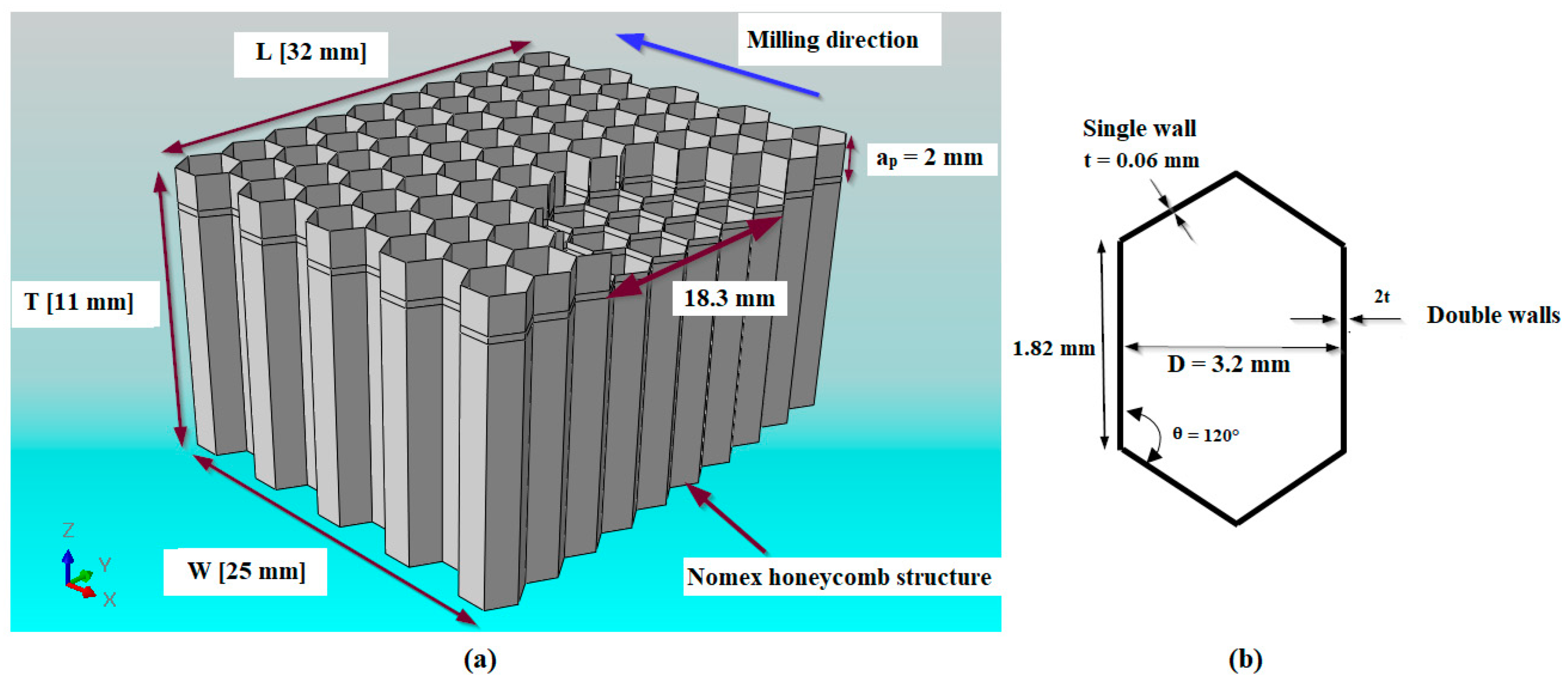
The material forming the honeycomb structure adopted for this study is Nomex. This material is made from aramid fibers immersed in the phenolic resin. Nomex paper is a very fragile material, therefore, the machining of this type of structure represents a technical and scientific challenge for engineers, and the shaping of this type of material requires very strict precautions. In this work, the choice of the geometry of the machined part and the geometric parameters used in the numerical simulation are based on the experimental work [23]. The geometric dimensions of the honeycomb structure and the hexagonal cell are shown, respectively, in Figure 1a,b.
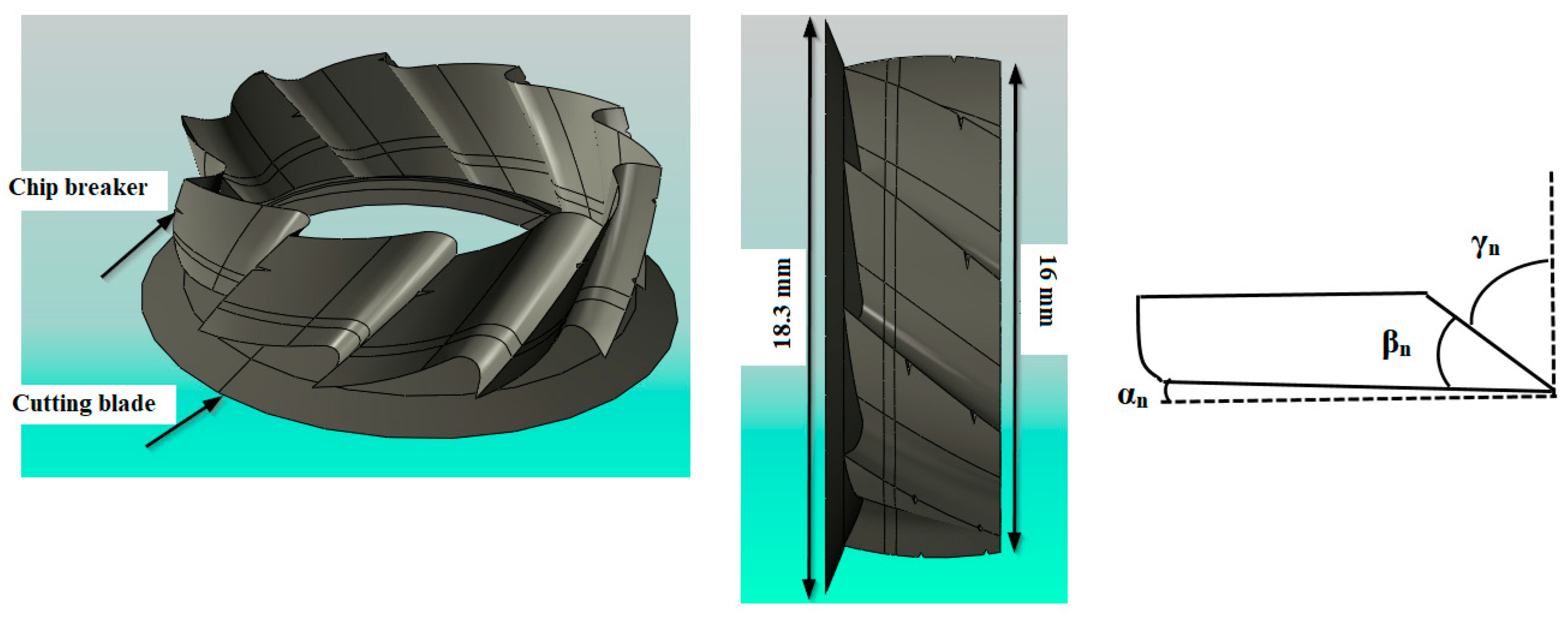
Due to the frangible behavior of Nomex paper, milling the Nomex honeycomb structure needs exceptional tools and a specific design. The cutting tool used here is the combined tool CZ10 provided by the company ‘EVATEC Tools’, and it consists of two parts: the lower part is a conical disc with a diameter of 18.3 mm, a rake angle of γn = 68°, a flank angle of αn = 2.5° and smooth edges [23]. The upper part is a milling cutter having helices carrying chip breakers (Figure 2).
2.2. Numerical Model of the Milling Processes
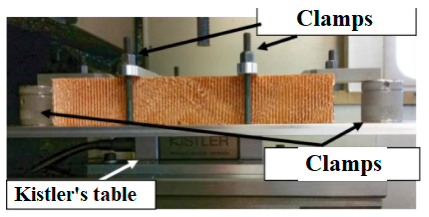
Throughout the numerical modeling of the milling, the cutting tool and the Nomex honeycomb structure must be subjected to the boundary conditions according to the real working conditions. During the numerical simulation, we considered that the cutting tool is more rigid than that of the structure. In other words, the thermomechanical properties of the cutting tool are not considered during the simulation. Based on the experimental approach, the Nomex honeycomb structure is fixed on the Kistler tabletop model 9129AA, which is mounted on the table of the machining center (Figure 3) [23]. During numerical modeling, it is assumed that the part is firmly held. Moreover, all the nodes located at the bottom of the part have been completely fixed. Equally, displacements of the nodes located on the vertical edge of the configuration have been blocked for all directions X and Y (Figure 4).
The present work focuses on the thermomechanical orthogonal cutting of the Nomex honeycomb structure. For this purpose, an explicit temperature displacement algorithm is selected. In this study, an explicit dynamic study was performed for the three-dimensional configuration by means of Abaqus simulation software developed using finite elements method. In this context, walls of the honeycomb structure are meshed using thermally coupled S4RT 4-node shell elements with a mesh element count of 73,656 (Figure 5a). In effect, the rigidity of the cutting tool is very strong compared to the Nomex honeycomb structure. Therefore, the tool whose deformation during machining is not considered is assumed rigid, with 3498 R3D4 rigid mesh elements (Figure 5b). Before subjecting the numerical model to calculation, we carefully checked the setting of nonlinear parameters that can lead to non-convergence or difficult convergence, such as mesh size and contact parameters. During numerical simulation, the small mesh size necessarily increases the total CPU calculation time and especially in the three-dimensional representation. For this purpose, a fine mesh was used during the 3D numerical simulation in order to obtain reliable results. As a result, the mesh size, which was chosen in this work, is 0.5 mm. During the milling of the Nomex structure, the movement of the cutting tool takes place in two directions, which are the feed movement along the OX axis and the rotational movement that occurs along OZ. For this reason, a reference point RP is fixed at the axis of revolution of the cutting tool from which the cutting conditions are assigned and the cutting forces are calculated (Figure 5b). In this work, the contact between the structure and the cutting tool was controlled by Coulomb’s law. Since the walls that form the alveolar structure are modeled by shell elements, the contact between the cutting tool and the part to be machined is considered as punctual. Therefore, a low friction coefficient value was adopted (µ = 0.15).
2.3. Behavioral Law of the Machined Material
Since the Nomex material is an aramid polymer coated with a phenolic resin, Nomex paper is often modeled as orthotropic or isotropic [24,25]. The shaping of the Nomex is performed by arranging aramid fibers arbitrarily in the three XYZ directions. Due to the softness and randomness of fiber accommodation, researchers are unable to directly determine its thermomechanical properties using standard techniques. Indeed, numerical and experimental studies prove that the mechanical characteristics of aramid fibers, which form the Nomex materials, are more coherent according to the main direction of the structure. In this work, the thermomechanical properties of Nomex paper have been extracted on the most recent works in the literature and are presented in the Table 1 [26,27].
2.4. Separation and Fracture Failure Criteria
The machining of the Nomex honeycomb structure is the mechanism of cutting material under the action of a cutting tool. Thus, the choice of the failure criterion is essential to carry out the machining simulation. The separation criteria are usually associated with the mechanical and thermal properties of the material. The shear failure criterion is applied in the present study, which is controlled by the finite element software Abaqus. The damage analysis procedure is carried out as follows. The initial thermomechanical properties at the start of the calculation are summarized in Table 1. The advancing movement of the cutting tool generates a force, which is exerted on the workpiece. The normal and shear dynamic stresses are calculated at the Gaussian points and at different interfaces. Consequently, the appropriate failure criteria are applied in order to predict the initiation as well as the propagation of the damage and this for several sequences of stacks. When the coefficient of destruction ω reaches the delicate value, which is equal to one, it means that the material is undone so the chips are generated. The value of the fracture coefficient ω can be obtained from the following formula:
where ∆ε is the equivalent plastic strain increment, εf is the total strain when the material is damaged and ω is the shaping limit value or destruction coefficient.
3. Results and Discussion
In order to study the phenomena during the milling cutting process of the Nomex honeycomb structure and the effects of different geometric parameters of the cutting tool, the developed FE model is first checked. Discussions are then conducted based on the validated FE model. The influence of geometric parameters including the diameters of the cutting tool and its wedge angles on the size of the chip, the cutting forces and the quality of the machined surface are evaluated.
3.1. Experimental Validation of the Proposed Model
3.1.1. Evolution of Tool Wear as a Function of Milling Conditions
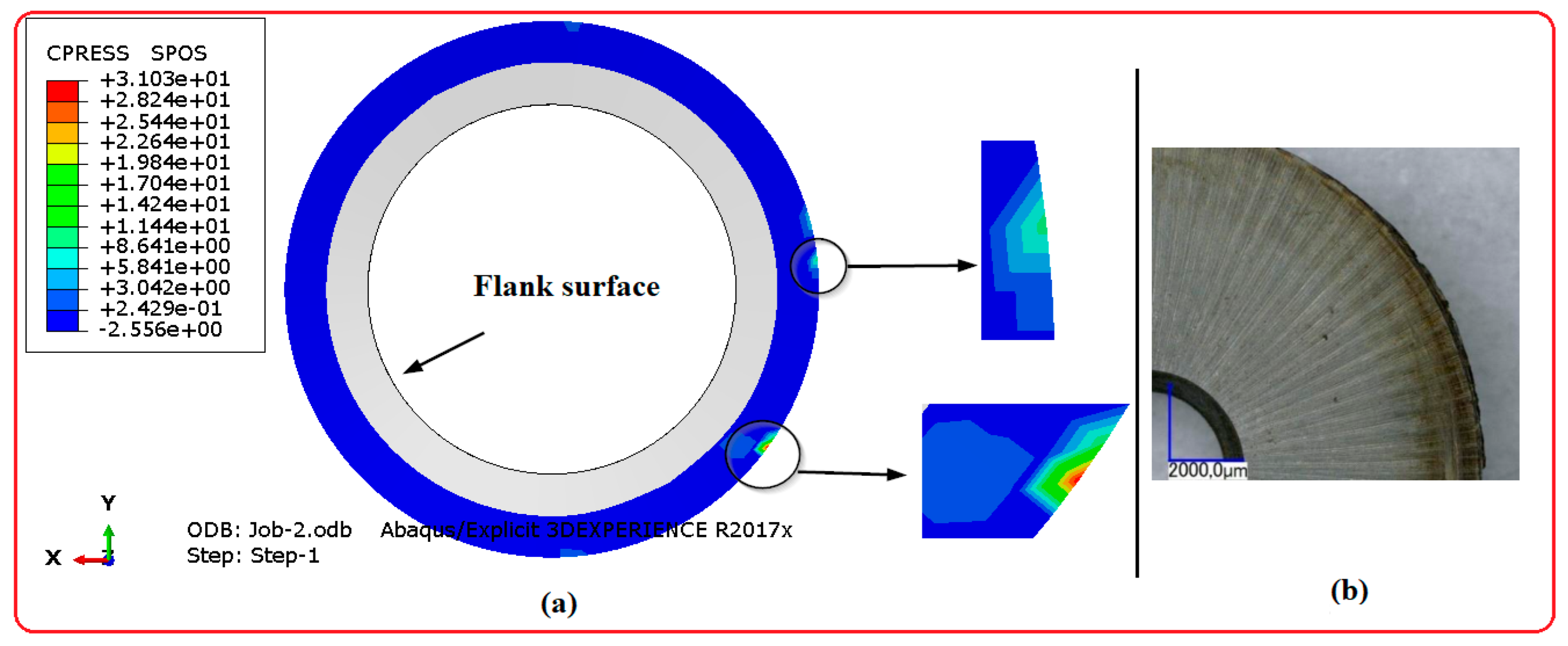
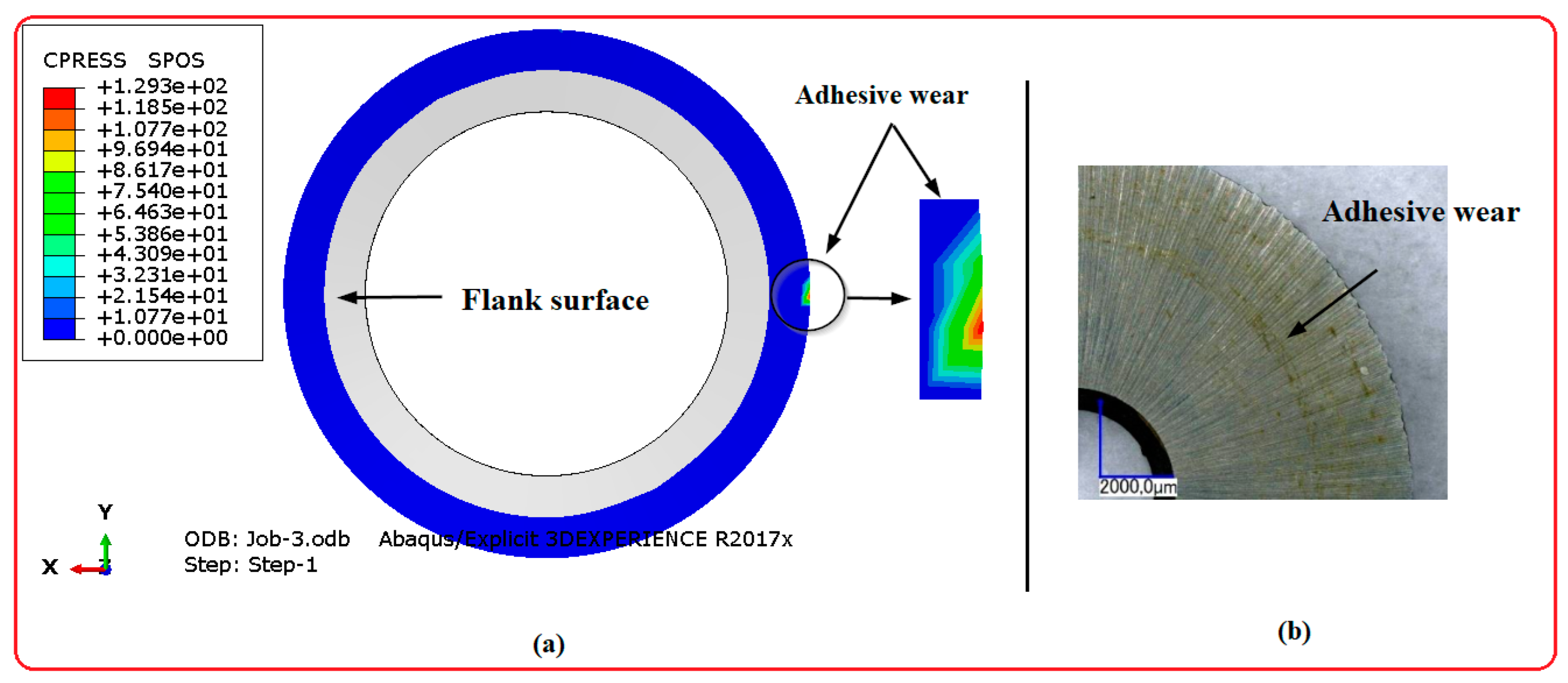
To properly achieve high quality parts in terms of the surface quality generated when milling the Nomex honeycomb structure, it is necessary to take into thought the factors influencing the wear of the cutting tool. Indeed, the most pronounced wear modes of cutting tools after machining conventional composite materials are chipping, abrasion and adhesive. These phenomena generally depend on the geometry of the tool and the mechanical behavior of the machined composite material [28,29,30]. In this regard, an experimental study has been conducted in the literature to highlight the influence of cutting conditions on the wear of the cutting tool during milling of the Nomex honeycomb structure [23]. Based on this work, the machining of the Nomex honeycomb favors the appearance of a “yellowish” powder on the CZ10 combined tool (Figure 6). The color of this dust indicates that it originates from the phenolic resin, which coats the aramid paper.
To validate the numerical model of milling of structures in Nomex honeycomb, numerical simulations were carried out to highlight the influence of the rotation speed on the adhesive wear of the cutting tool. In this study, two rotation speeds were studied, namely 2000 rpm and 23,000 rpm with a constant feed rate of 200 mm/min. The simulations were carried out in a duration of 0.6 s, which means that the lateral depth is of the order of 2 mm. The comparison between the results from the numerical model and those resulting by experience has been made based on a visual examination (Figure 7 and Figure 8). As it was pointed out previously, the CZ10 cutting tool consists of two parts: the milling cutter and the cutting blade. However, the cutting blade is the most stressed element during the milling operation of the Nomex honeycomb structure, because it is in direct contact with the machined surface and its role is to cut and separate the walls of the Nomex to generate chips.
According to the results presented, we determined that the wear of the cutting tool by adhesive is closely related to the rotation speeds of the cutting tool. In this context, the formation of a colored band near the cutting edge is observed as a function of the rotation speeds adopted. In this regard, experimental studies have shown that the chips resulting from Nomex honeycomb milling with high rotation speeds (23,000 rpm) and low feed rates (200 mm/min) are in powder form consisting of aramid fibers and phenolic resin cut into fine particles. Thus, wear by adhesive is explained by the contact between the cutting tool and the chips generated, which are in the form of powder under these cutting conditions [18,23,31]. On the contrary, for low rotation speed and low speeds of advance (200 mm/min; 2000 rpm), the quantity of material in powder form becomes lower. This is due to the total change in the size of the chips generated for these cutting conditions, which become bulky [31]. Therefore, the yellow color band is less visible for these cutting conditions. From the point of view of numerical simulation, the resulting contact pressure between the cutting blade and the chips generated revealed the wear of the adhesive of the cutting tool. Based on the obtained results, we concluded that the experimental results are compatible with the numerical results. As a result, the numerical model is able to identify adhesive wear of the cutting tool.
3.1.2. Evolution of Machined Surface Quality as a Function of Milling Conditions
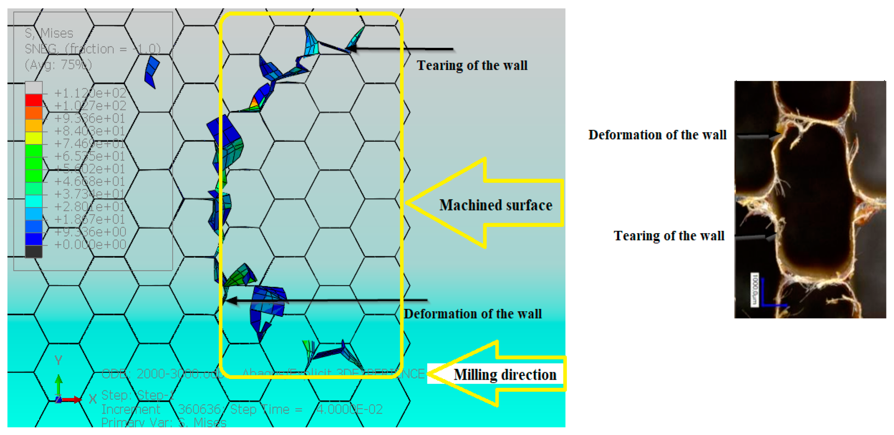
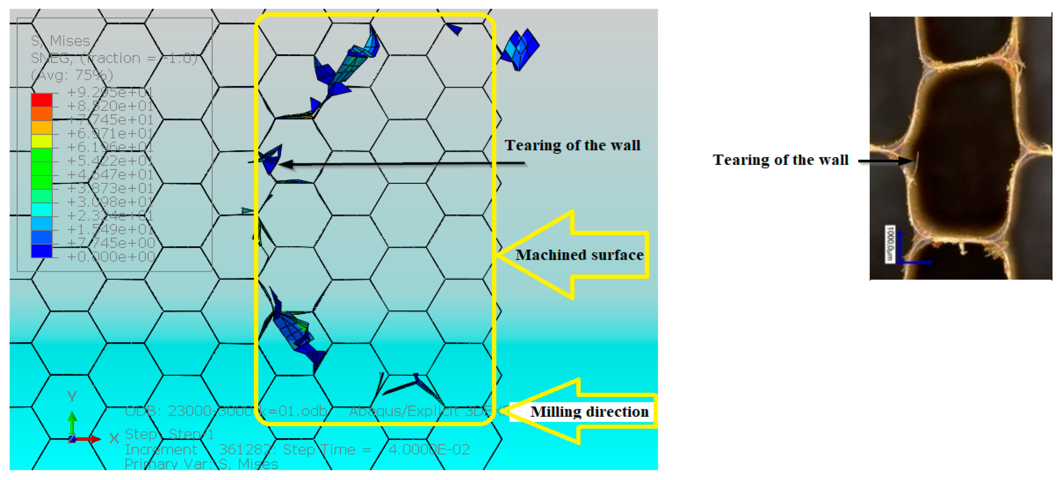
The surface quality of the honeycomb structure is of key priority for the shaping of the sandwich structure. It is based on the assembly by gluing the two skins and the machined surfaces of the honeycomb structure. Therefore, to avoid delamination and breakage of the structure, it is essential to take into consideration the quality of surface. Indeed, the making of materials involves a strong relationship between the cutting tool and the part. In this direction, many works show that the machining of composite materials contains a strong relationship between the surface quality produced and the cutting conditions [32,33,34]. Since the structure of the Nomex honeycomb core is made of aramid fiber paper and phenolic resin, studies show that burrs and tears of the walls are the main machining defects of the core in Nomex honeycomb [35,36,37]. To shed light on the influence of the rotation speed on the surface quality during the milling of the Nomex honeycomb structure, numerical studies were conducted under the machining conditions (3000 mm/min; 23,000 rpm) and (3000 mm/min; 2000 rpm). The simulations were performed for 0.04 s, so the machined side depth is 2 mm. The results obtained by the numerical model were compared with the results from experience and under the same real milling conditions [23]. The comparison was made based on a visual examination by the naked eye. The obtained results are presented in Figure 9 and Figure 10.
The obtained results show that the quality of the surface is carefully linked to the milling conditions. In this regard, we have noticed that the main milling defects of the Nomex honeycomb structure are wall tears and uncut aramid fibers. However, the burrs are not visible by the numerical simulation because the walls forming the honeycomb structure have been modeled by shell elements. Overall, we determined that the tearing of the walls is more pronounced for low rotation speeds. When milling the Nomex honeycomb structure, the low rotation speed of the cutting tool causes the thin walls of the Nomex to bend until they tear. As a result, the generated surface quality improves for high rotation speeds. In the end, by comparing the obtained results, it is clear that the results from the numerical model are associated with the experimental results [23].
4. Effect of Cutting Tool Geometry on Machinability of Nomex Honeycomb Structure
Based on bibliographical research and with regard to the needs defined by industrial partners, the choice of cutting tools when milling Nomex honeycomb structures is made according to a phenomenological and mechanistic approach by means of an experimental test. The choice of cutting tools is based on the requirement of the quality of the machined surface and the severe wear of the cutting tool while respecting the machining conditions used. Indeed, experimental tests are very expensive in terms of execution. In addition, the high rotation speeds prevent the visualization of the cutting process for each step. As a result, the experimental procedure fails to follow the milling process of Nomex honeycomb structures. Consequently, numerical simulation is a robust tool that allows the analysis of all phenomena and mechanisms at low cost. The numerical model developed was validated with experimental tests. Thus, it is obvious to study and analyze the geometric parameters on the machining quality. In this work, the focus is on the effect of wedge angle and cutting blade diameter on cutting forces, surface quality, chip size, and material buildup in front of the tool.
4.1. Influence of the Gap between the Two Elements of the Cutting Tool on the Chip Size
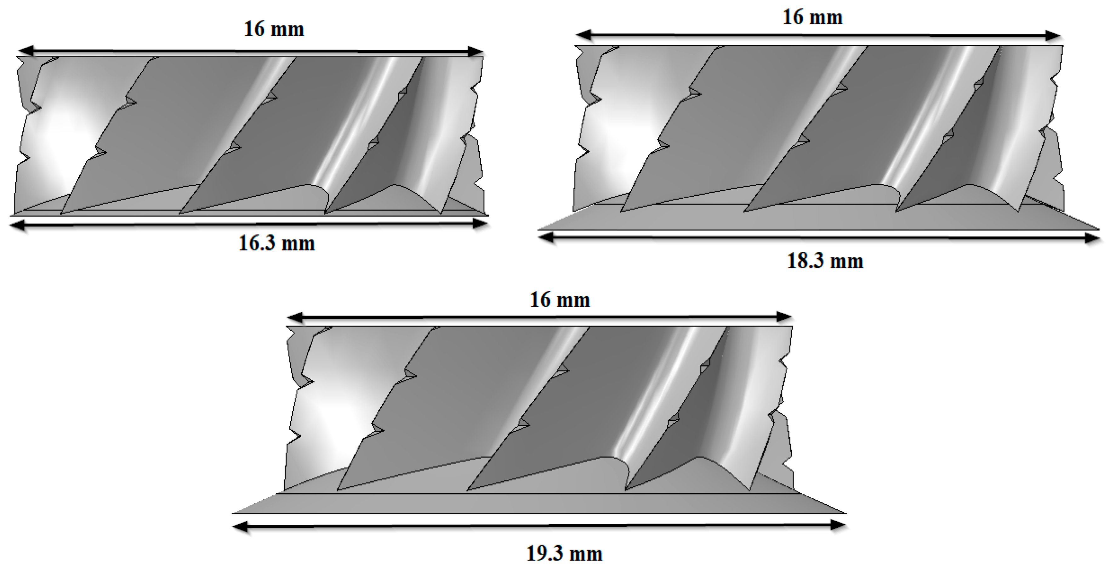
The cutting of Nomex honeycomb structures attracts the attention of several authors [38]. The cutting tool used here consists of two parts, the milling cutter and the cutting blade. Indeed, the cutting of the honeycomb core structure is completed in two phases. First, the cutter blade cuts through the thin walls that float on top of the cutter blade until it reaches the milling cutter, which has the job of chipping and pushing chips away. This process is closely linked to the cutting conditions, namely feed rates and rotation speeds [31]. To consider the solutions necessary to optimize the geometry of the tool when milling the Nomex honeycomb structure, numerical simulations have been made to highlight the influence of the difference in diameters of two components of cutting tool on the size of the chips generated. To achieve this, we designed a new cutting tool while maintaining the geometric dimensions of the milling cutter nonetheless; we changed the diameters of the cutting blade (Figure 11). To properly analyze the effect of the gap between the two components of the tool on the chip size, the cutting conditions were adopted as unfavorable during the experimental phase to known (2000 rpm, 3000 mm/min) and for a short duration corresponding to 0.04 s, which means that the lateral depth is of the order of 2 mm. The obtained results are shown in Figure 12, Figure 13 and Figure 14.
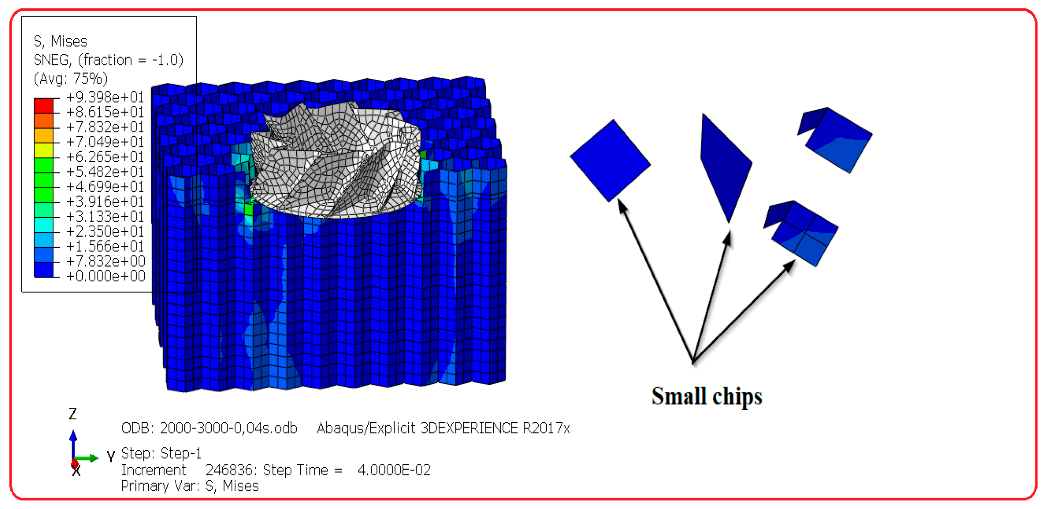
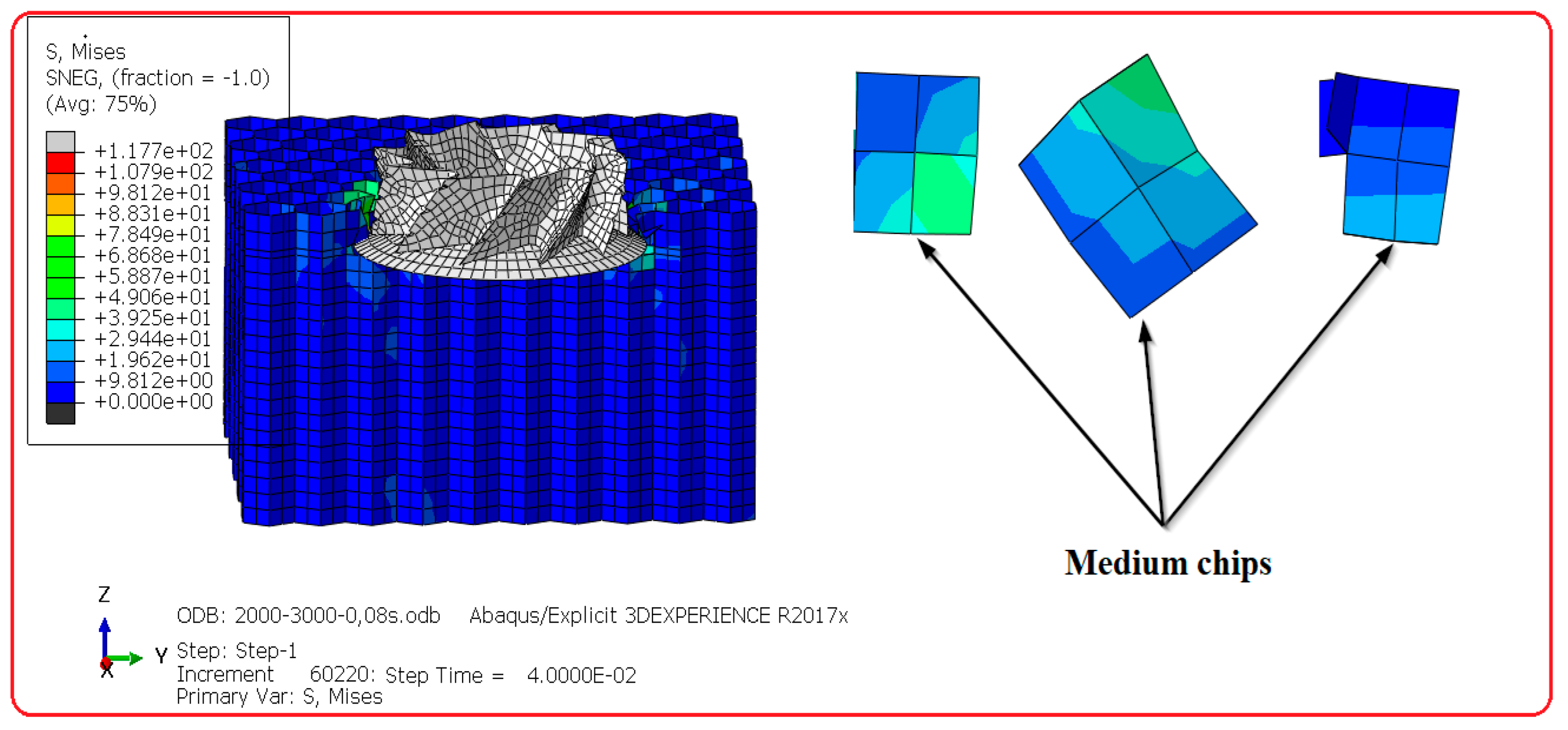
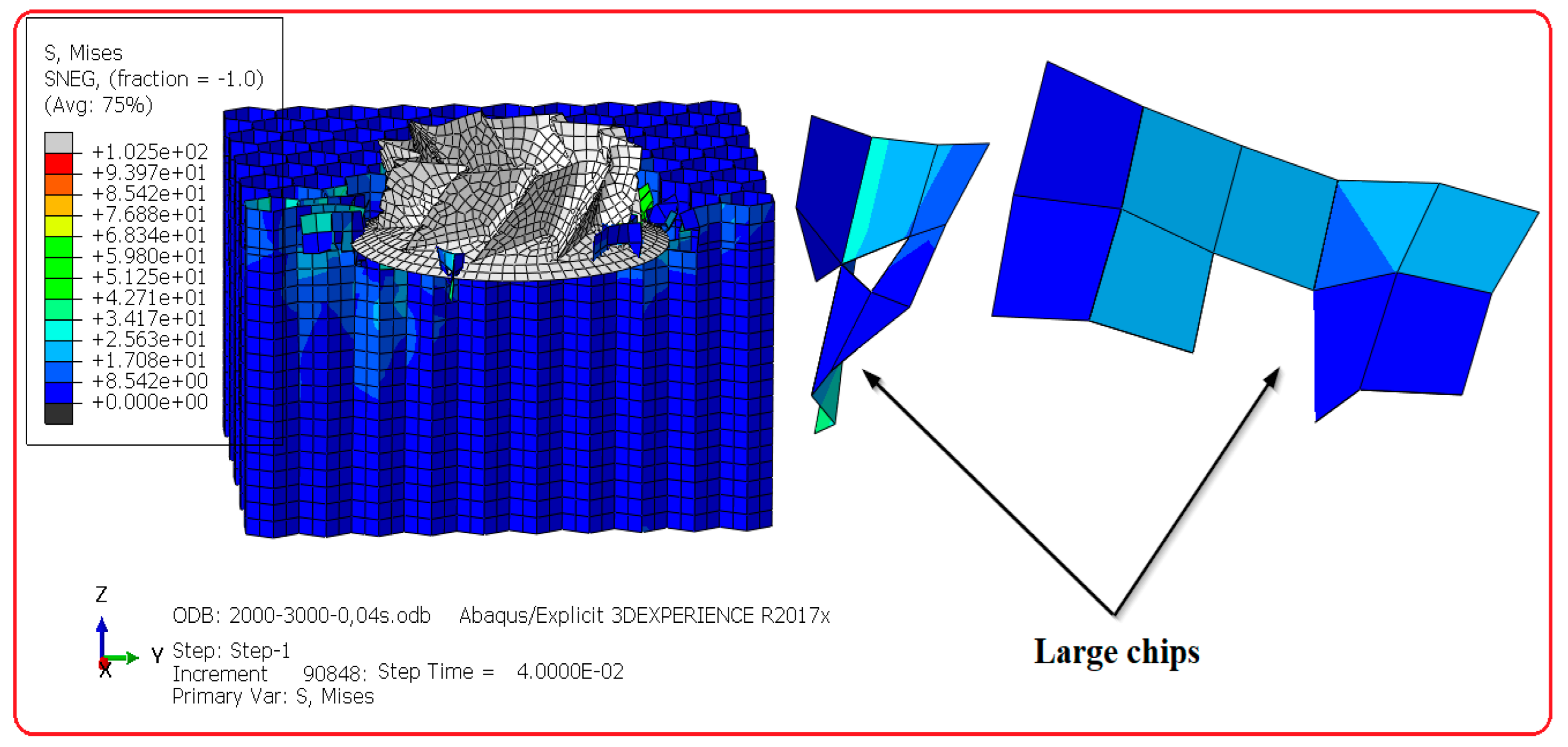
In view of the obtained results, it is clear that the size of the chips generated during the milling of the Nomex honeycomb structures are closely associated with the gap between the cutting blade and the milling cutter. The process of chip formation when milling Nomex honeycomb structures occurs in two stages. First, the cutting blade cuts the thin walls. Then, the cut walls slide on the upper face of it until reaching the upper part of the tool, which has the role of shredding and pushing back the chips. Based on this phenomenon, the walls cut by the 16.3 mm cutting blade arrive at the milling cutter faster, which facilitates the formation and evacuation of chips. Consequently, the small gap between the two elements of the cutting tool (milling cutter + cutting blade) promotes the formation of small chips. On the contrary, the walls cut by the 18.3 mm and 19.3 mm diameter knives do not easily reach the milling cutter due to the strong gap between the cutting miller and cutting blade. As a result, the large difference in diameters between the two components of the cutting tool generates large chips. Based on these results, it is concluded that the gap between the two elements of the cutting tool has a remarkable influence on the size of the chips, so that the size of the chips increases with the difference in diameters between the two components of the cutting tool. Therefore, when milling the honeycomb structure, it is essential to take into consideration the gap between the two cutting millers and cutting blade. Moreover, we consider it important to mention that large chips are undesirable in industrial sectors, since this causes the formation of clusters at the level of the cutting edge, which promotes premature wear of the cutting tool.
4.2. Influence of the Gap between the Two Elements of Cutting Tool on the Cutting Forces
In this section, we study the influence of the gap between two elements of the cutting tool (milling cutter + cutting blade) on the cutting force and its components when milling the Nomex honeycomb structure. To properly analyze the effect of the gap between the two components of the tool on the cutting force, the cutting conditions were adopted as unfavorable during the experimental phase to known (2000 rpm, 3000 mm/min) and for 0.04 s, i.e., the machined lateral depth is 2 mm. The obtained results are presented in Figure 15 and Figure 16.
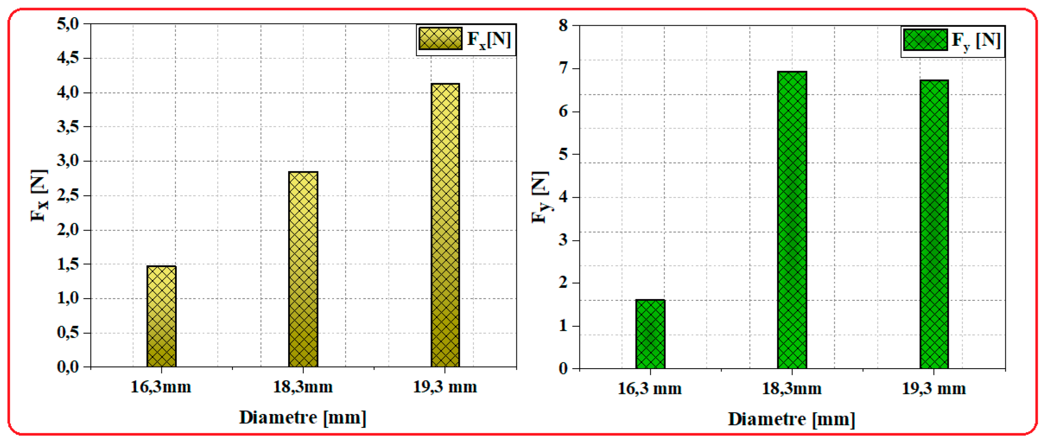
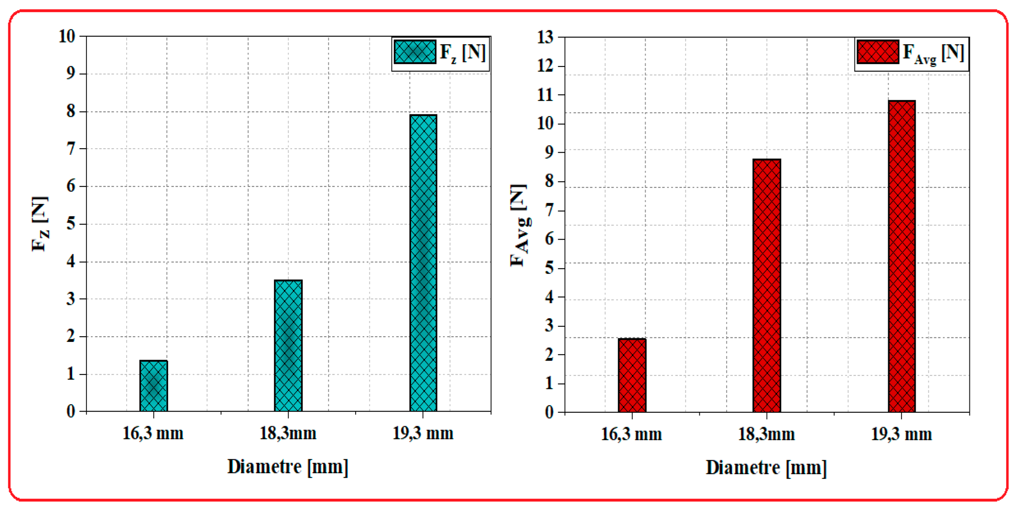
According to the obtained results, it is clear that the machining forces are deeply associated with the gap between the two elements of the cutting tool. In this sense, we determined that the feed component Fx increases as a function of the difference in diameter of the cutting tool. This is due to the accrual of material on the face of the cutting tool, which promotes increased resistance of the accumulated material. In addition, we noticed that the crushing component Fz increases with the variation of diameters of the cutting tool in a regular way. This is explained by the strong contact between the flank surface of the cutting tool and the surface of the honeycomb structure, which is characterized by a good mechanical property in the vertical direction. Regarding the cutting component Fy, it was determined that these values are not steady, as a function of the diameter difference such as the forces increase to between 16.3 mm and 18.3 mm, and then decrease to between 18.3 mm and 19.3 mm. This anomaly is clarified by the robust relation of the restoring force of the walls of the Nomex paper at the cutting zone. Therefore, when the element reaches the critical failure value, it is removed to form a new chip. The removal of the elements leads to a loss of contact amid the part and the tool; consequently, the forces decrease. In addition, the uncut walls generate return forces in the opposite direction of rotation of the cutting tool and therefore generate an increase in the cutting force. In this paragraph, it is discovered that the gap between the two elements of the cutting tool has an influence on the cutting forces. Thus, to enhance the maturity of the cutting tool, it is critical to consider this parameter.
4.3. Effect of the Gap between the Two Elements of Cutting Tool on the Machined Surface Quality
The quality of the generated surface is associated with several parameters in particular (cutting conditions, tool geometry, vibration of the machine tool, etc.). Composite materials are characterized by the appearance of uncut fibers, tearing of fibers, and thermal degradation of the resin [39,40,41]. In this section, we observe the influence of the gap between the two elements of the cutting tool (milling cutter + cutting blade) on the quality of the machined surface during milling of the Nomex honeycomb structure. To this end, numerical studies were conducted below the same cutting conditions (23,000 rpm, 3000 mm/min). The simulations were realized over 0.06 s, so the machined lateral depth is 3 mm. The qualification and analysis of the surface quality resulting from the numerical model was based on a visual examination of the naked eye. The obtained results are shown in Figure 17, Figure 18 and Figure 19.
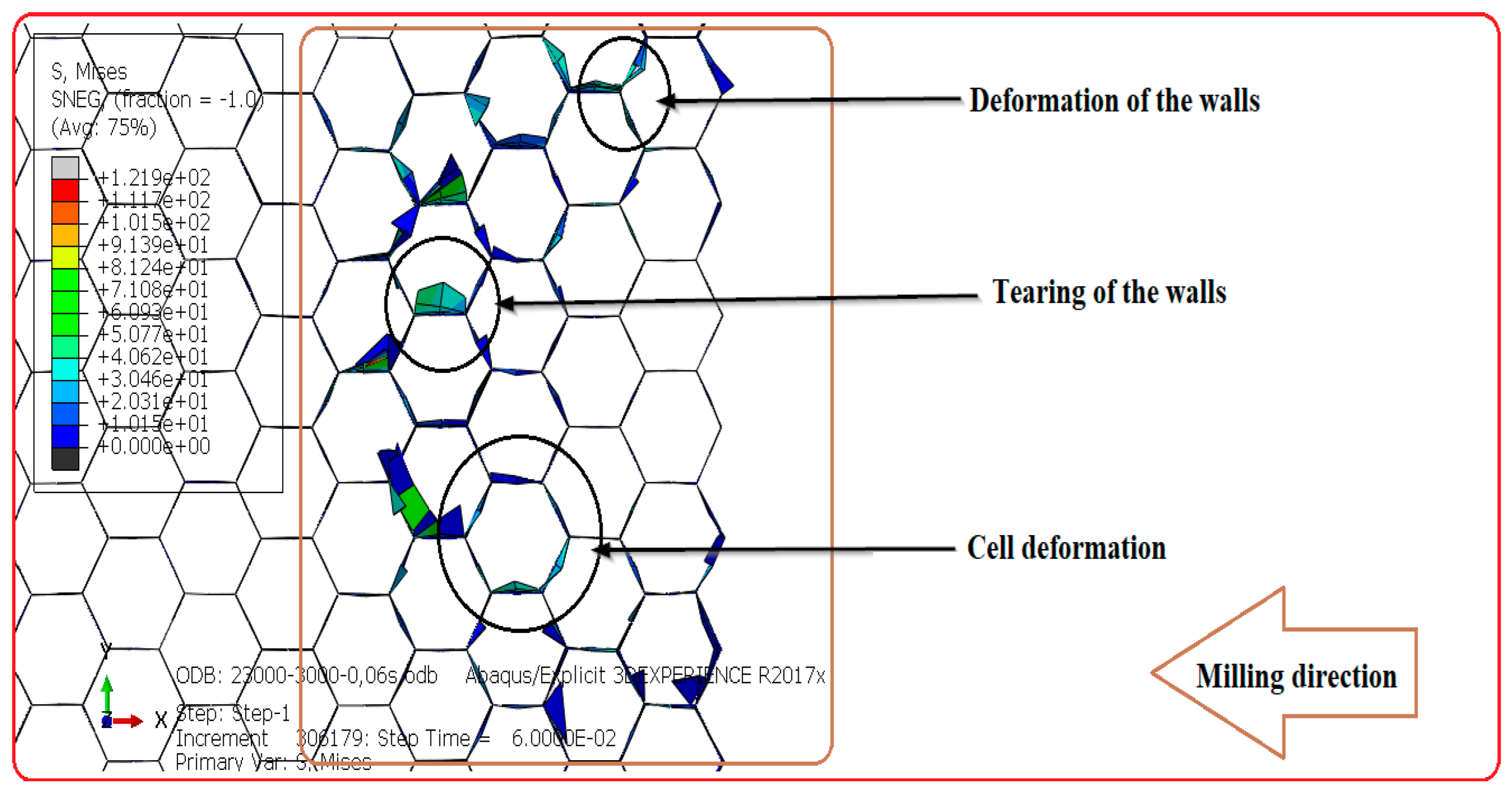
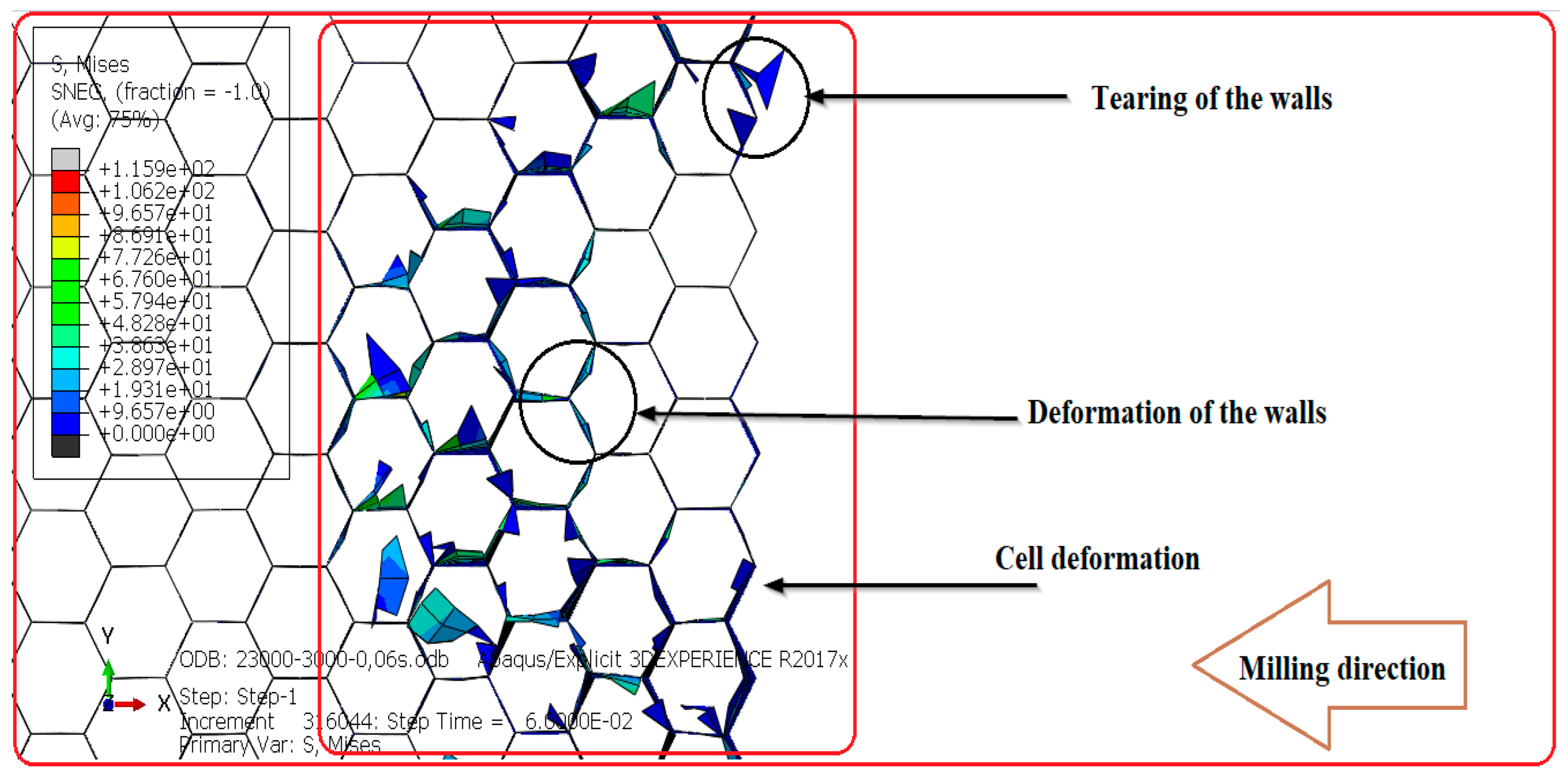
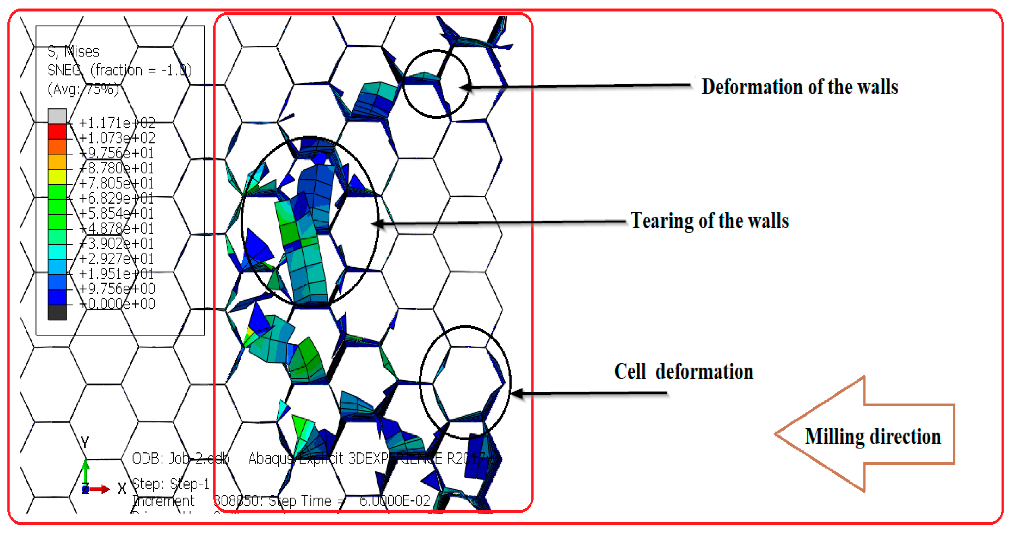
In the present study, the developed numerical model discloses three machining flaws throughout the milling of the Nomex honeycomb structure. The most common machining defects are tearing of the walls, deformation of the walls and deformation of the cells. Nevertheless, the numerical model does not show the burrs caused by the accumulation of material. This is due to the fact that the thin walls which form the structure were modeled by shell elements. Considering the obtained results, it was determined that the quality of the machined surface is associated with the differences between the two components of the cutting tool, so that the quality of the machined surface deteriorates with increase in the diameter of the cutting blade. The large diameter of the cutting tool bends the thin walls of the Nomex honeycomb structure until they tear. In the end, to better meet the requirements of the industrial sectors concerned in terms of machined surface quality, it is necessary to take into consideration the gap between the two elements of the cutting tool.
4.4. Effect of the Wedge Angle on the Accrual of Material
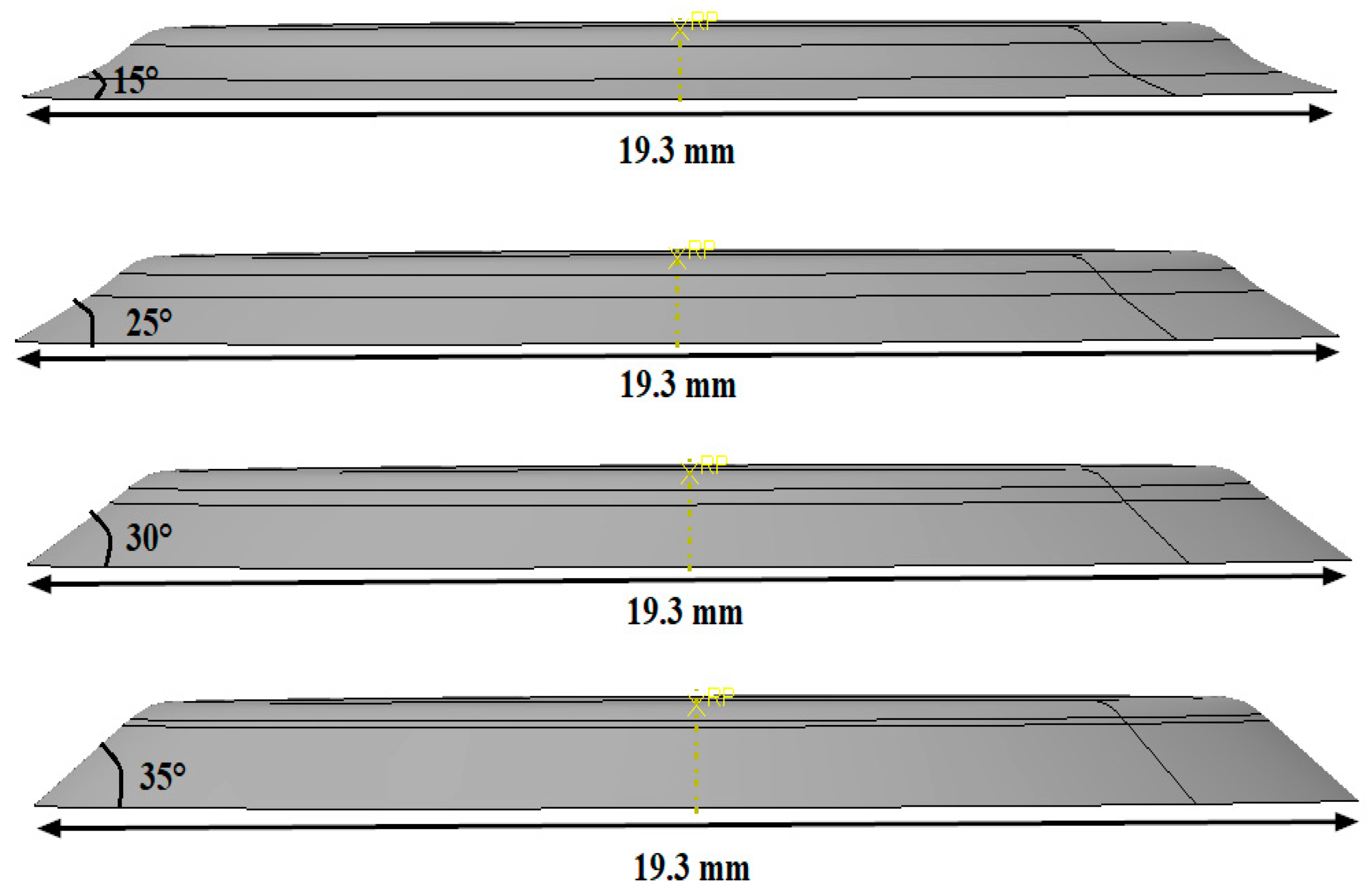
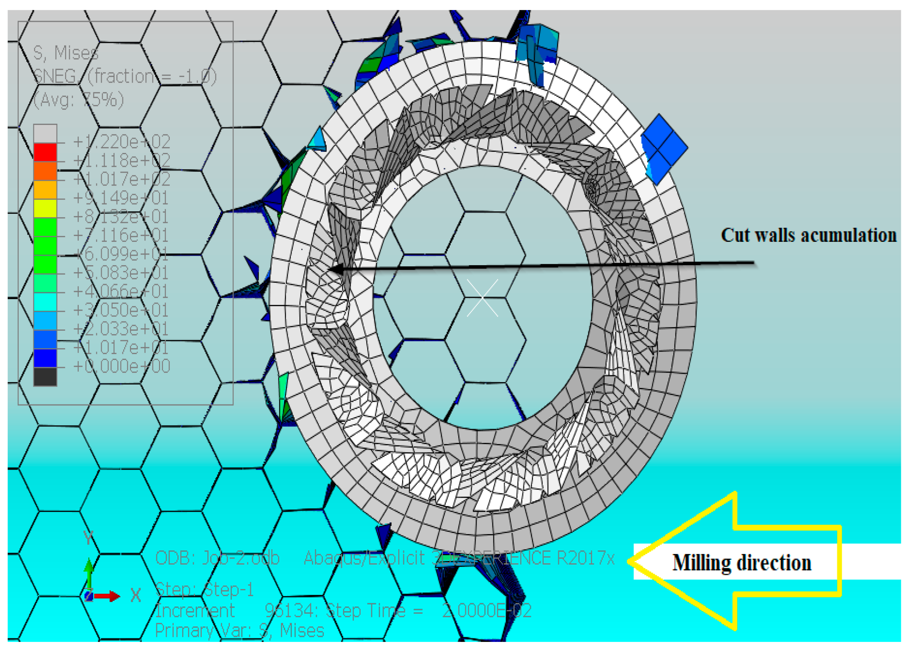
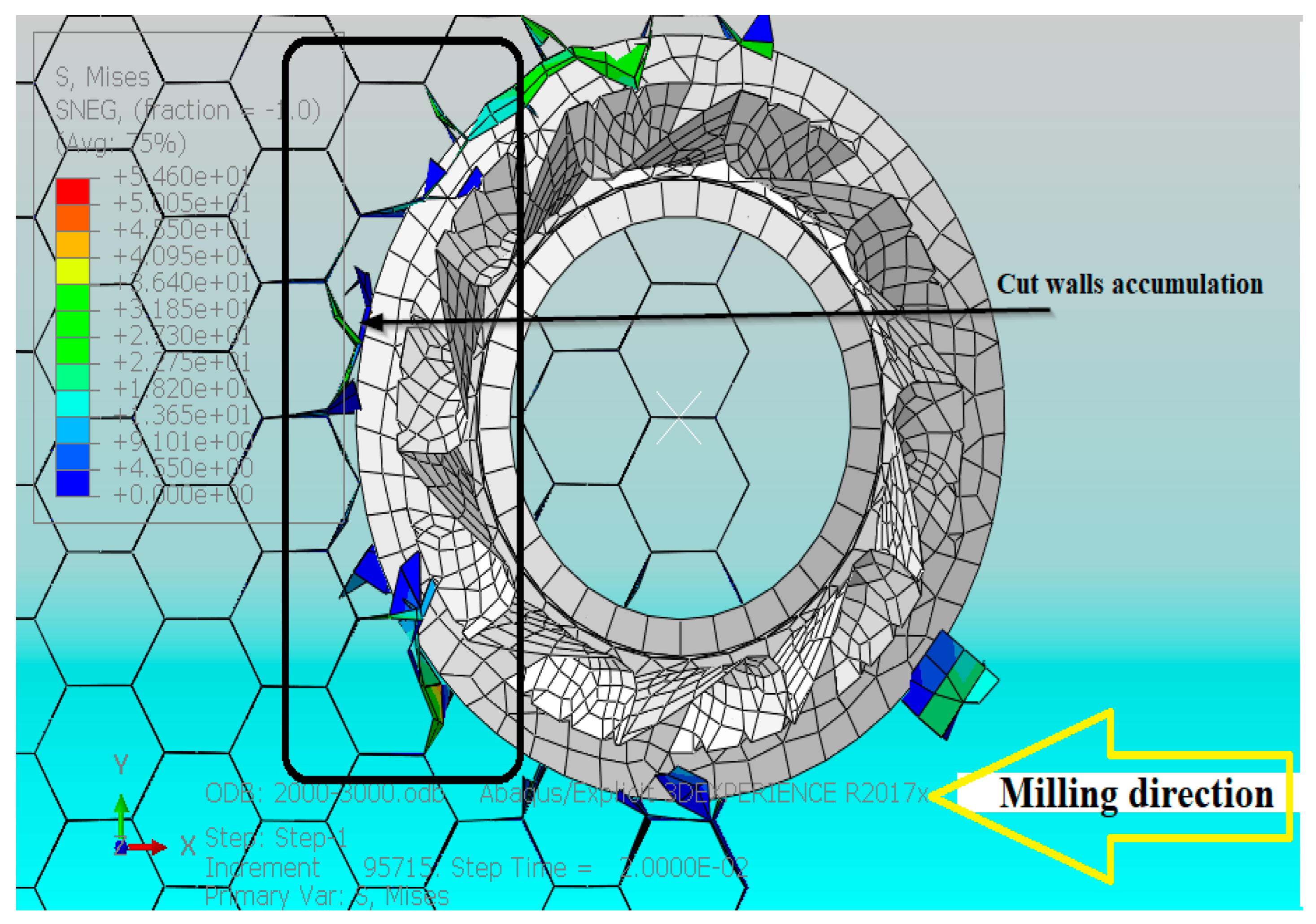
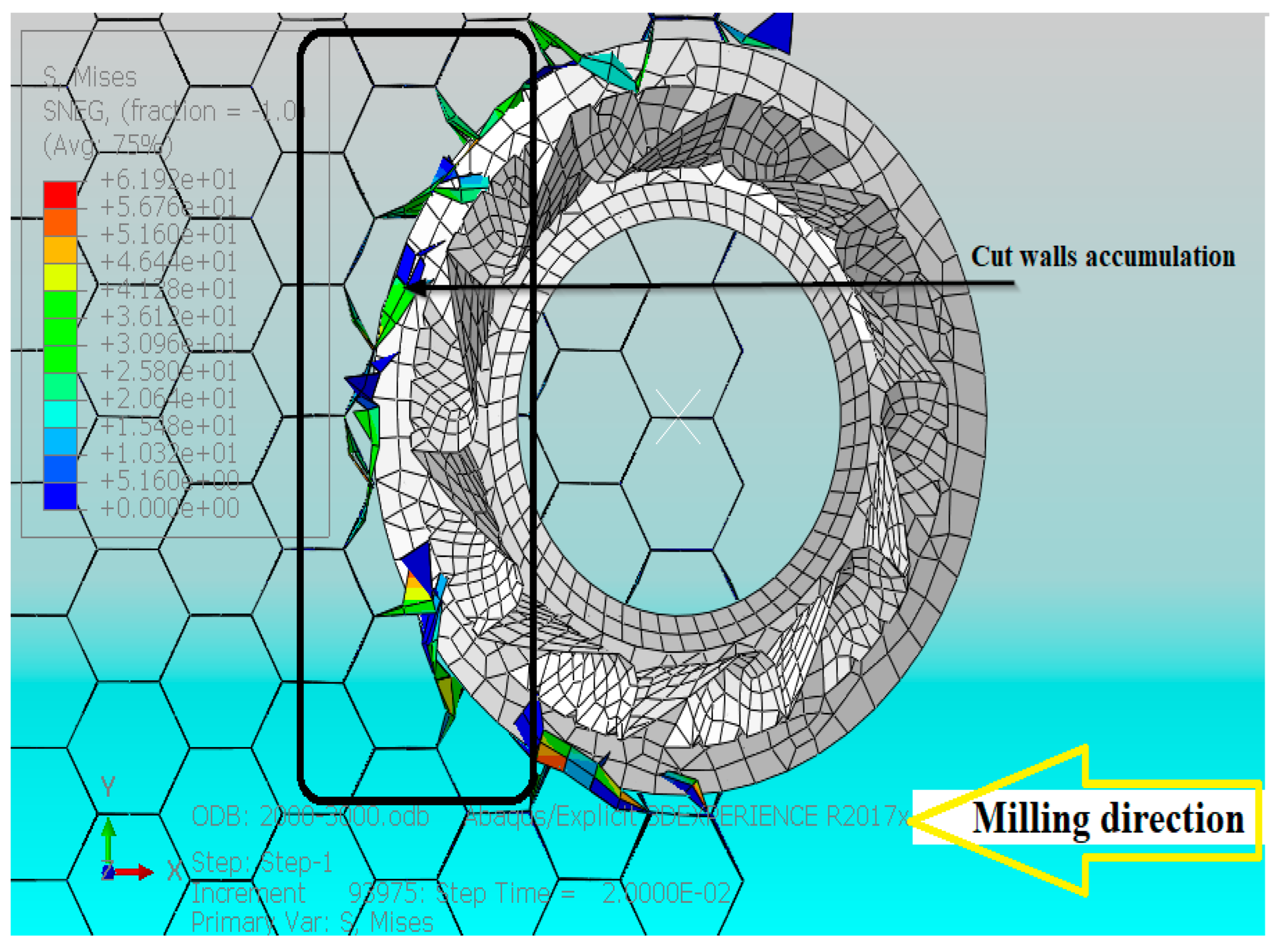
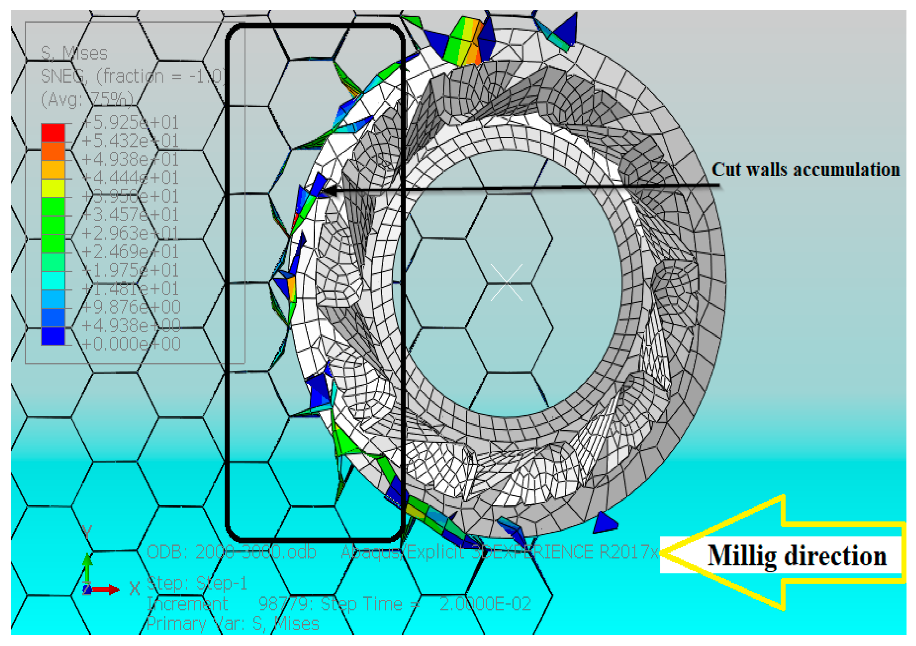
In this section, we deem it important to consider the cutting tool optimization paths when milling Nomex honeycomb structures in terms of the wedge angle. To this end, a numerical study was conducted to highlight the effect of the wedge angle on the accrual of material on the face of the cutting tool. To achieve this, four wedge angles were tested, namely 15°, 25°, 30° and 35° (Figure 20). The numerical simulations were executed under the same machining conditions (23,000 rpm, 3000 mm/min) and for a short duration of 0.04 s, which means that the lateral depth is 2 mm. Figure 21, Figure 22, Figure 23 and Figure 24 summarize the obtained results.
In view of the obtained results, it is clear that the accrual of material in the face of the cutting tool is very sensitive to the wedge angles of the cutting tool, so that the accrual of material is more pronounced for large angles. In this case, the chips formed do not easily reach the cutter due to the steep slope formed by the cutting surface and the flank surface. As a result, chips accrue in the face of the cutting tool, thus increasing feed forces. On the contrary, for small wedge angles, the walls cut by the cutting blade reach the milling cutter more quickly and easily, which causes the crushing and evacuating of the chips, as well as subsequent formation of small chips and reduction in cutting forces. In this context, it should be emphasized that the chips formed must be infinitely small in order to overcome the problems of formation of clumps of material at the level of the cutting edge, thus avoiding wear of the tool.
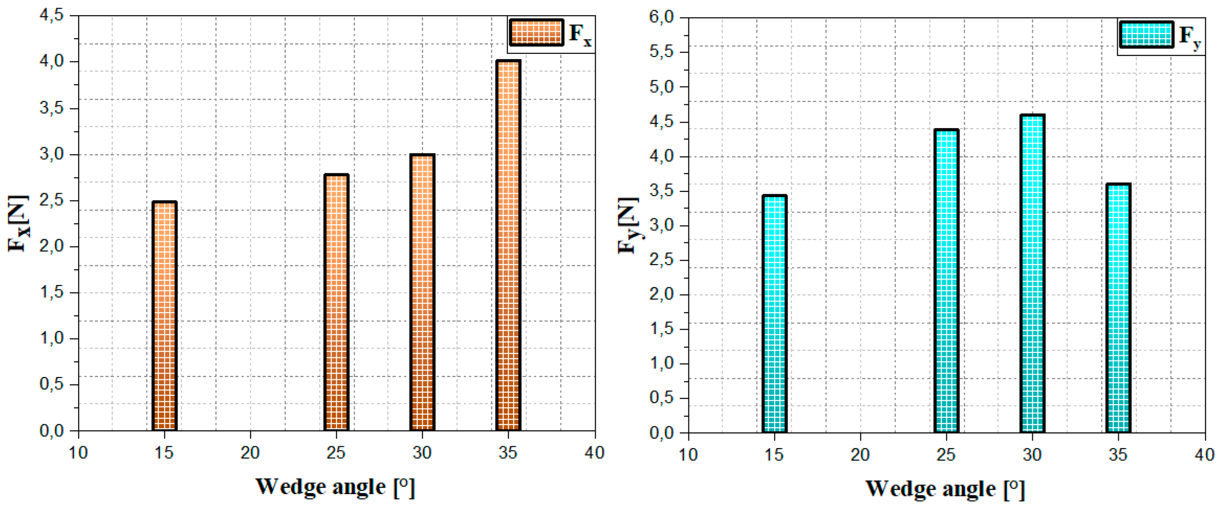
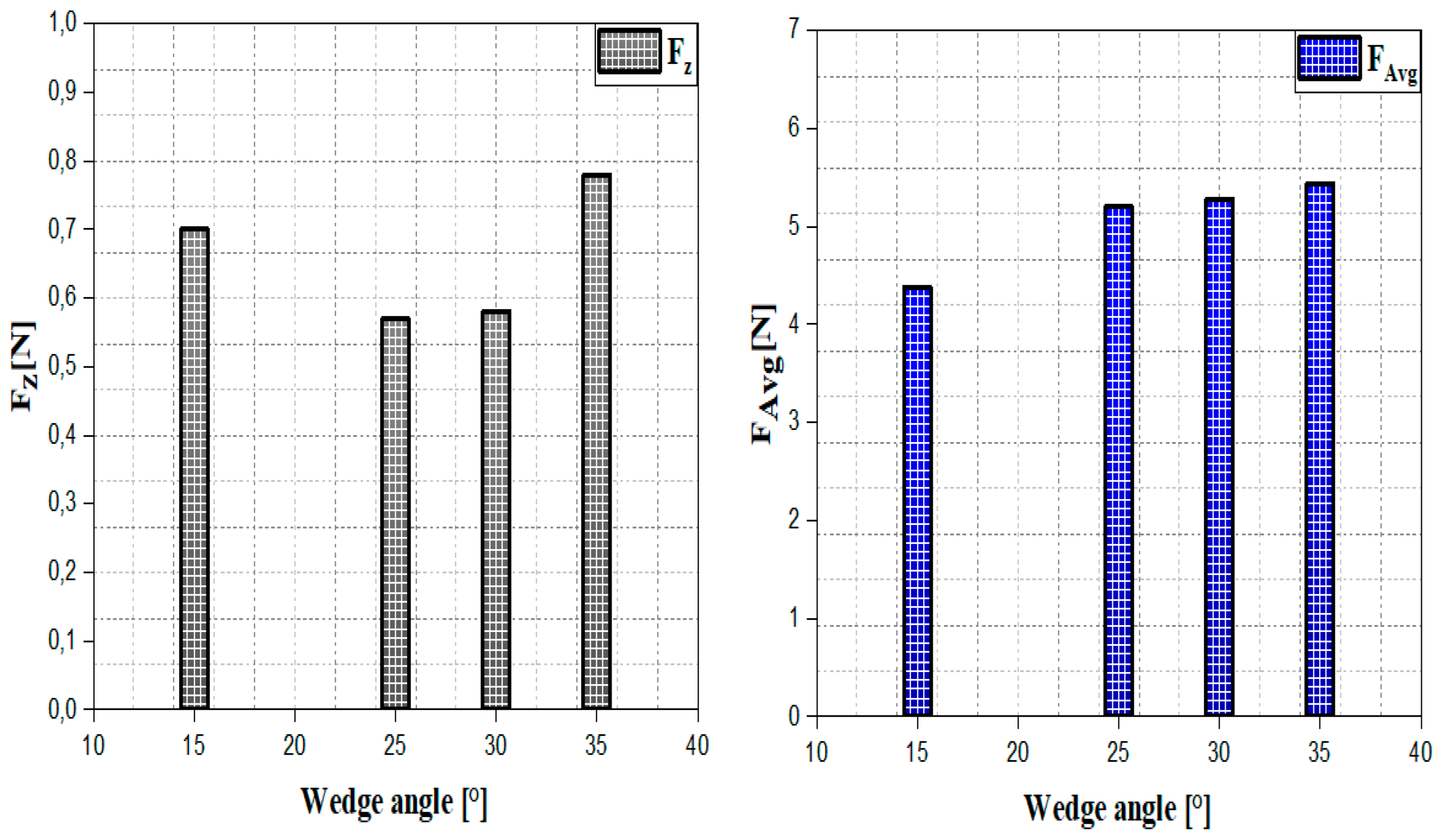
4.5. Influence of the Wedge Angle on the Cutting Forces
The cutting forces are of paramount importance in predicting premature wear of the cutting tool. In this section, we highlight the effect of the wedge angle of the cutting blade on the cutting forces using the numerical model developed. To achieve this, we varied the wedge angles, namely 15°, 25°, 30° and 35°. The Numerical studies were executed under the same machining conditions (3000 mm/min, 23,000 rpm) and for a short duration of 0.04 s, which means that the machined lateral depth is of the order of 2 mm. The obtained results are reported in Figure 25 and Figure 26.
As seen from obtained results, it is noticeable that the cutting forces are sensitive to the wedge angles of the cutting blade. Firstly, we determined that the feed component Fx increases with the increase in the wedge angle of the cutting tool due to the accrual of material on the face of the cutting tool. As explained earlier, the large wedge angle causes large slopes between the flank surface and the rake surface. Therefore, the cut walls do not easily reach the cutter to shred them. As a result, the walls accumulate in the face of the cutting tool and favor the increase in the advance efforts due to the resistance of the materials. On the other hand, we determined that the values of the cutting component Fy are not stable between 15° and 35°, so that the forces increase between 15° and 30°, and then decrease between 30° and 35°. This irregularity is explicated by the solid relation of the restoring force of the walls of the Nomex paper at the flank face. Therefore, when the element reaches the critical failure value, it is detached to give rise to a chip. The removal of the elements leads to a loss of contact between the part and the tool; consequently, the forces decrease. In addition, the uncut walls generate return forces in the opposite direction of rotation of the cutting tool and therefore generate an increase in the cutting force. Similarly, we noticed that the curve representing the variations of the crushing force Fz as a function of the wedge angle is quasi-stationary and its maximum value does not exceed 0.74N. This means that the wedge angle has no effect on crushing in the vertical direction. Finally, to properly predict the machinability of the Nomex honeycomb structure, it is indispensable to take into consideration the wedge angle of cutting blade.
5. Conclusions
To accurately predict the machinability of the Nomex honeycomb structure, it is important to consider various factors, including cutting tool wear, machined surface quality, chip size, material buildup in front of the cutting tool and cutting forces. A complete 3D FE numerical model is developed which fully takes into account the thermomechanical behavior of the Nomex paper forming the honeycomb structure and the complex parameters of the hexagonal cell and the cutting tool. The proposed model explains the contact of the cutting tool and the hexagonal structure with different specifications (including specific wall thicknesses and angles of the cutting tool). Numerical model is validated with experimental tests. Influence of various milling parameters on the machinability performance of the Nomex honeycomb structure is automatically investigated by finite element cutting simulation. Some conclusions can be reached, as follows:
- The rotation speeds of the cutting tool have a direct influence on the wear of the cutting tool by bonding, so that the wear is well noticed for the high rotational speeds. The results from the numerical model are well associated with the results of the experiment.
- The rotation speeds have a direct influence on the machined surface quality so that the high rotational speeds optimize the surface quality. The results from the numerical model are well correlated with the results of the experiment.
- The proposed numerical model is able to predict the influence of the gap between the two elements of cutting tool on chip size. The obtained results show that the gap between the two components of the cutting tool has a direct influence on the size of the chips so that the large gaps generate large chips and vice versa.
- The influence of the gap between the two elements of cutting tool on the cutting force and its components has been well established. The results show that the component Fx increases with large deviations. This is clarified by the accrual of material in the face of the cutting tool. In addition, the crushing component in the vertical direction increases as a function of the difference in diameters. This is related to the permanent contact of the lower surface of the tool and the upper surface of the structure.
- The influence of the gap between the two elements of cutting tool on the surface quality was studied. The obtained results indicate that the surface quality deteriorates for the largest gap between the milling and the cutting blade.
- The proposed model is able to predict the influence of the wedge angle of the cutting blade on the accrual of material on the face of the cutting tool. The obtained results show that the accumulation of material is more pronounced for large wedge angles. This is associated with the steep slopes formed by the flank surface and the cut surface.
- The influence of the wedge angle on the cutting force and its components is well examined. The results illustrate that the feed component is larger for large wedge angles. This is linked to the accrual of material in the face of the tool. In addition, we noticed that the crushing component Fz is quasi-stationary. This means that the wedge angle has no effect on the component in the vertical direction.
- The established results are of considerable importance for optimizing the machinability of the Nomex honeycomb structure in the relevant industrial sectors.
- Finally, it is concluded that the geometric parameters of the cutting tool have an influence on the shaping of the Nomex honeycomb structure and the optimization of these parameters considerably improves the integrity of the cutting tool and the quality of the machined surface.
Author Contributions
Conceptualisation, T.Z., M.N. and H.M.; Methodology, T.Z. and M.N.; Supervision, M.N.; Forma analysis, T.Z., M.N. and H.M.; Investigation, T.Z., M.N. and H.M.; Original draft, T.Z., M.N. and H.M. All authors have read and agreed to the published version of the manuscript.
Funding
Not applicable.
Institutional Review Board Statement
Not applicable.
Informed Consent Statement
Not applicable.
Data Availability Statement
Not applicable.
Acknowledgments
Not applicable.
Conflicts of Interest
The authors declare no conflict of interest.
References
- Cognard, P. Collage des Composites; Ed. Techniques Ingénieur: Paris, France, 2003. [Google Scholar]
- Guillemot, J.; Grunevald, Y. Les Composites en Construction Ferroviaire; Ed. Techniques Ingénieur: Paris, France, 1998. [Google Scholar]
- Reyne, M. Les Composites Dans les Sports et les Loisirs; Ed. Techniques Ingénieur: Paris, France, 1998. [Google Scholar]
- Norville, H.; Tibor, E. Process for Machining Expanded Honeycomb. U.S. Patent No 3,413,708, 1968. [Google Scholar]
- Hirayama, A. Method for Cutting Honeycomb Core. U.S. Patent No 6,740,268, 2004. [Google Scholar]
- Wang, F.; Liu, J.; Li, L.; Shu, Q. Green machining of aluminum honeycomb treated using ice fixation in cryogenic. Int. J. Adv. Manuf. Technol. 2017, 92, 943–952. [Google Scholar] [CrossRef]
- Dan, L.; Mathiew, J. Tool Wear Failure Monitoring Technique for Turning. Int. J. Mach. Tools Manuf. 1990, 30, 579–598. [Google Scholar] [CrossRef]
- Wu, W.; Li, S.; Qin, X.; Liu, W.; Cui, X.; Li, H.; Shi, M.; Liu, H. Effects of fiber orientation on tool wear evolution and wear mechanism when cutting carbon fiber reinforced plastics. Chin. J. Aeronaut. 2022. [Google Scholar] [CrossRef]
- Sharma, V.K.; Singh, T.; Singh, K.; Kaur, G. MQL assisted face milling of EN-31: Tool wear optimization and its correlation with cutting temperature. Mater. Today Proc. 2022, 71, 346–351. [Google Scholar] [CrossRef]
- Usca, Ü.A.; Uzun, M.; Şap, S.; Kuntoğlu, M.; Giasin, K.; Pimenov, D.Y.; Wojciechowski, S. Tool wear, surface roughness, cutting temperature and chips morphology evaluation of Al/TiN coated carbide cutting tools in milling of Cu–B–CrC based ceramic matrix composites. J. Mater. Res. Technol. 2022, 16, 1243–1259. [Google Scholar] [CrossRef]
- Devillez, A.; Lesko, S.; Mozer, W. Cutting tool crater wear measurement with white light interferometry. Wear 2004, 256, 56–65. [Google Scholar] [CrossRef]
- El-Wardany, T.I.; Gao, D.; Elbestawi, M.A. Tool condition monitoring in drilling using vibration signature analysis. Int. J. Mach. Tools Manuf. 1996, 36, 687–711. [Google Scholar] [CrossRef]
- Ma, K.; Wang, J.; Zhang, J.; Feng, P.; Yu, D.; Ahmad, S. A force-insensitive impedance compensation method for giant magnetostriction ultrasonic cutting system of Nomex honeycomb composites. Compos. Struct. 2022, 294, 115708. [Google Scholar] [CrossRef]
- Nouari, M. Modélisation de L’usure par Diffusion des Outils de Coupe en Usinage Grande Vitesse. Master’s Thesis, Université de Metz, Metz, France, 2000. [Google Scholar]
- Rawat, S.; Attia, H. Wear mechanisms and tool life management of WC–Co drills during dry high speed drilling of woven carbon fibre composites. Wear 2009, 267, 1022–1030. [Google Scholar] [CrossRef]
- Faraz, A.; Biermann, D.; Weinert, K. Cutting edge rounding: An innovative tool wear criterion in drilling CFRP composite laminates. Int. J. Mach. Tools Manuf. 2009, 49, 1185–1196. [Google Scholar] [CrossRef]
- Park, K.H.; Beal, A.; Kim, D.D.W.; Kwon, P.; Lantrip, J. Tool wear in drilling of Composite/titanium stacks using carbide and polycrystalline diamond tools. Wear 2011, 271, 2826–2835. [Google Scholar] [CrossRef]
- Jaafar, M.; Atlati, S.; Makich, H.; Nouari, M.; Moufki, A.; Julliere, B. A 3D FE modeling of machining process of Nomex® honeycomb core: Influence of the cell structure behaviour and specific tool geometry. Procedia CIRP 2017, 58, 505–510. [Google Scholar] [CrossRef]
- Zarrouk, T.; Salhi, J.E.; Nouari, M.; Salhi, M.; Chaabelasri, E.; Makich, H.; Salhi, N. Modeling machining of aluminum honeycomb structure. Int. J. Adv. Manuf. Technol. 2022, 123, 2481–2500. [Google Scholar] [CrossRef]
- Fischer, S.; Drechsler, K.; Kilchert, S.; Johnson, A. Mechanical tests for foldcore base material properties. Compos. Part A Appl. Sci. Manuf. 2009, 40, 1941–1952. [Google Scholar] [CrossRef]
- Seemann, R.; Krause, D. Numerical modelling of Nomex honeycomb cores for detailed analyses of sandwich panel joints. In Proceedings of the 11th World Congress on Computational Mechanics (WCCM XI), Barcelona, Spain, 20–25 July 2014. [Google Scholar]
- Zarrouk, T.; Salhi, J.E.; Atlati, S.; Nouari, M.; Salhi, M.; Salhi, N. Study on the behavior law when milling the material of the Nomex honeycomb core. Mater. Today Proc. 2021, 45, 7477–7485. [Google Scholar] [CrossRef]
- Jaafar, M.; Makich, H.; Nouari, M. A new criterion to evaluate the machined surface quality of the Nomex® honeycomb materials. J. Manuf. Process. 2021, 69, 567–582. [Google Scholar] [CrossRef]
- Roy, R.; Nguyen, K.H.; Park, Y.B.; Kweon, J.H.; Choi, J.H. Testing and modeling of Nomex TM honeycomb sandwich Panels with bolt insert. Compos. Part B Eng. 2014, 56, 762–769. [Google Scholar] [CrossRef]
- Ivañez, I.; Moure, M.M.; Garcia-Castillo, S.K.; Sanchez-Saez, S. The oblique impact response of composite sandwich plates. Compos. Struct. 2015, 133, 1127–1136. [Google Scholar] [CrossRef] [Green Version]
- Zhang, S.F.; Wang, J.F.; Ma, F.J.; Liu, Y.; Sha, Z.H. Simulation analysis of the effect of tool parameters on the cutting force and temperature of ultrasonic cutting honeycomb core. J. Dalian Jiaotong Univ. 2017, 38, 57–61. [Google Scholar]
- Jin, C.Z. Research on Nomex Honeycomb Material High-Speed Processing Technology and Retention Reliability; Zhejiang University: Zhejiang, China, 2006. [Google Scholar]
- Zhou, X.; Gao, Y.; Wang, Y.; Xiao, P.; Huang, X. Effects of ZrC particles, load and sliding speed on the wear behavior of the ZrC/2024Al composites. Wear 2022, 506, 204465. [Google Scholar] [CrossRef]
- Moharami, A.; Qodosi, P. Enhanced dry sliding friction and wear behaviors of Mg–Mg2Si composites. Compos. Commun. 2022, 36, 101365. [Google Scholar] [CrossRef]
- Jiang, L.; Wan, Y.; Zhang, N.; Fu, J.; Li, X.; Zhang, X.; Du, P. Erosive wear characteristics of styrene butadiene rubber and silicon dioxide-filled wood–plastic composites. J. Build. Eng. 2022, 56, 104791. [Google Scholar] [CrossRef]
- Zarrouk, T.; Salhi, J.E.; Atlati, S.; Nouari, M.; Salhi, M.; Salhi, N. Modeling and numerical simulation of the chip formation process when machining Nomex. Environ. Sci. Pollut. Res. 2022, 29, 98–105. [Google Scholar] [CrossRef] [PubMed]
- Cao, W.; Zha, J.; Chen, Y. Cutting force prediction and experiment verification of paper honeycomb materials by ultrasonic vibration-assisted machining. Appl. Sci. 2020, 10, 4676. [Google Scholar] [CrossRef]
- Zarrouk, T.; Salhi, J.E.; Nouari, M.; Salhi, M.; Atlati, S.; Salhi, N.; Makich, H. Analysis of friction and cutting parameters when milling honeycomb composite structures. Adv. Mech. Eng. 2021, 13, 16878140211034841. [Google Scholar] [CrossRef]
- Sun, J.; Wang, Y.; Zhou, P.; Wang, M.; Kang, R.; Dong, Z. Equivalent mechanical model of resin-coated aramid paper of Nomex honeycomb. Int. J. Mech. Sci. 2022, 240, 107935. [Google Scholar] [CrossRef]
- Geng, D.; Zhang, D.; Xu, Y.; He, F.; Liu, D.; Duan, Z. Rotary ultrasonic elliptical machining for side milling of CFRP: Tool performance and surface integrity. Ultrasonics 2015, 59, 128–137. [Google Scholar] [CrossRef]
- Khairusshima, M.N.; Hassan, C.C.; Jaharah, A.G.; Amin, A.K.M.; Idriss, A.M. Effect of chilled air on tool wear and workpiece quality during milling of carbon fibre-reinforced plastic. Wear 2013, 302, 1113–1123. [Google Scholar] [CrossRef]
- Zitoune, R.; El Mansori, M.; Krishnaraj, V. Tribo-functional design of double cone drill implications in tool wear during drilling of copper mesh/CFRP/woven ply. Wear 2013, 302, 1560–1567. [Google Scholar] [CrossRef]
- Sun, D.; Kang, R.; Wang, Y.; Guo, J.; Dong, Z. A Novel Ultrasonic Trepanning Method for Nomex Honeycomb Core. Appl. Sci. 2020, 11, 354. [Google Scholar] [CrossRef]
- Saleem, M.; Toubal, L.; Zitoune, R.; Bougherara, H. Investigating the effect of machining processes on the mechanical behavior of composite plates with circular holes. Appl. Sci. Manuf. 2013, 55, 169–177. [Google Scholar] [CrossRef]
- Teti, R. Machining of composite materials. CIRP Ann. Manuf. Technol. 2002, 51, 611–634. [Google Scholar] [CrossRef]
- Haddad, M.; Zitoune, R.; Bougherara, H.; Eyma, F.; Castanié, B. Study of trimming damages of CFRP structures in function of the machining processes and their impact on the mechanical behavior. Compos. Part B Eng. 2014, 57, 136–143. [Google Scholar] [CrossRef]
Figure 1.
(a) Dimensions of the honeycomb structure; (b) dimensions of the hexagonal cell.

Figure 2.
Geometric dimensions of the CZ10 cutting tool used during the simulation.

Figure 3.
Experimental milling setup of the Nomex honeycomb structure [23].
Figure 3.
Experimental milling setup of the Nomex honeycomb structure [23].

Figure 4.
Boundary conditions used in the numerical simulation.

Figure 5.
(a) Mesh used in the FE model; (b) cutting conditions defined at reference point RP: N is the rotation speed and Vf is the feed rate.
Figure 5.
(a) Mesh used in the FE model; (b) cutting conditions defined at reference point RP: N is the rotation speed and Vf is the feed rate.

Figure 6.
Accumulation of yellow powder on the CZ10 cutting tool.

Figure 7.
Topographical analysis of the adhesive strip on the flank surface of the saw blade (23,000 rpm, 200 mm/min): (a) numerical result; (b) experimental result.
Figure 7.
Topographical analysis of the adhesive strip on the flank surface of the saw blade (23,000 rpm, 200 mm/min): (a) numerical result; (b) experimental result.

Figure 8.
Topographical analysis of the adhesive strip on the flank surface of the saw blade (2000 rpm, 200 mm/min): (a) numerical result; (b) experimental result.
Figure 8.
Topographical analysis of the adhesive strip on the flank surface of the saw blade (2000 rpm, 200 mm/min): (a) numerical result; (b) experimental result.

Figure 9.
Comparison between the surface quality resulting from the numerical simulation and the surface quality determined from the experiment. The cutting conditions: 3000 mm/min and 2000 rpm.
Figure 9.
Comparison between the surface quality resulting from the numerical simulation and the surface quality determined from the experiment. The cutting conditions: 3000 mm/min and 2000 rpm.

Figure 10.
Comparison between the surface quality resulting from the numerical simulation and the surface quality determined from the experiment. The cutting conditions: 3000 mm/min and 23,000 rpm.
Figure 10.
Comparison between the surface quality resulting from the numerical simulation and the surface quality determined from the experiment. The cutting conditions: 3000 mm/min and 23,000 rpm.

Figure 11.
CZ10 cutting tool to different diameters the cutting blade.

Figure 12.
Resulting chip size by the diameter-cutting blade of 16.3 mm.

Figure 13.
Resulting chip size by the diameter-cutting blade of 18.3 mm.

Figure 14.
Resulting chip size by the diameter-cutting blade of 19.3 mm.

Figure 15.
Evolution of Fx and Fy.

Figure 16.
Evolution of Fz and FAvg.

Figure 17.
Resulting machined surface quality by the cutting blade of 16.3 mm.

Figure 18.
Resulting machined surface quality by the cutting blade of 18.3 mm.

Figure 19.
Resulting machined surface quality by the cutting blade of 19.3 mm.

Figure 20.
CZ10 cutting tool in relation to different diameters the cutting blade.

Figure 21.
Accrual of material in the face of the cutting tool; wedge angle of the cutting blade is βn = 15°.
Figure 21.
Accrual of material in the face of the cutting tool; wedge angle of the cutting blade is βn = 15°.

Figure 22.
Accumulation of material in front of the cutting tool: the cutting blade of the wedge angle βn = 25°.
Figure 22.
Accumulation of material in front of the cutting tool: the cutting blade of the wedge angle βn = 25°.

Figure 23.
Accrual of material in the face of the cutting tool; wedge angle of the cutting blade is βn = 30°.
Figure 23.
Accrual of material in the face of the cutting tool; wedge angle of the cutting blade is βn = 30°.

Figure 24.
Accrual of material in the face of the cutting tool; wedge angle of the cutting blade is βn = 35°.
Figure 24.
Accrual of material in the face of the cutting tool; wedge angle of the cutting blade is βn = 35°.

Figure 25.
Evolution of Fx and Fy.

Figure 26.
Evolution of Fz and FAvg.


Disclaimer/Publisher’s Note: The statements, opinions and data contained in all publications are solely those of the individual author(s) and contributor(s) and not of MDPI and/or the editor(s). MDPI and/or the editor(s) disclaim responsibility for any injury to people or property resulting from any ideas, methods, instructions or products referred to in the content. |
© 2023 by the authors. Licensee MDPI, Basel, Switzerland. This article is an open access article distributed under the terms and conditions of the Creative Commons Attribution (CC BY) license (https://creativecommons.org/licenses/by/4.0/).
Share and Cite
MDPI and ACS Style
Zarrouk, T.; Nouari, M.; Makich, H. Simulated Study of the Machinability of the Nomex Honeycomb Structure. J. Manuf. Mater. Process. 2023, 7, 28. https://doi.org/10.3390/jmmp7010028
AMA Style
Zarrouk T, Nouari M, Makich H. Simulated Study of the Machinability of the Nomex Honeycomb Structure. Journal of Manufacturing and Materials Processing. 2023; 7(1):28. https://doi.org/10.3390/jmmp7010028
Chicago/Turabian StyleZarrouk, Tarik, Mohammed Nouari, and Hamid Makich. 2023. "Simulated Study of the Machinability of the Nomex Honeycomb Structure" Journal of Manufacturing and Materials Processing 7, no. 1: 28. https://doi.org/10.3390/jmmp7010028