1. Introduction
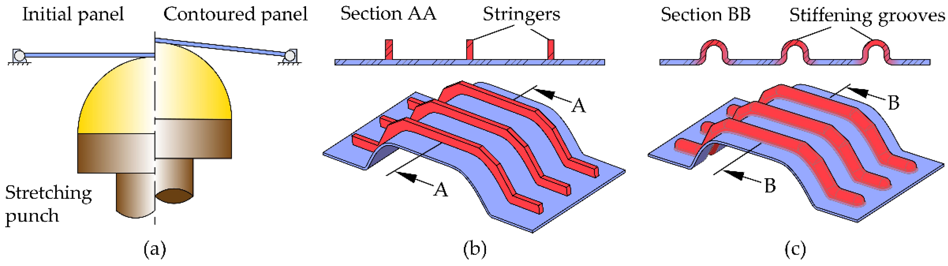
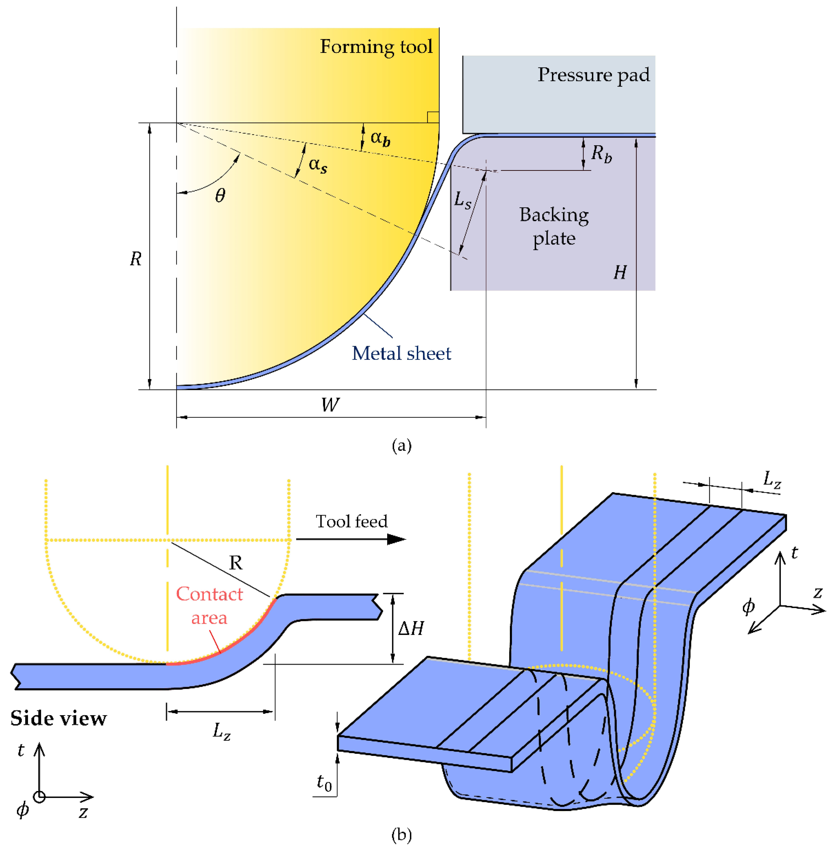
Stretching is a metal forming process in which an initially flat sheet, gripped along its edges, is stretched and bent simultaneously with the intention of obtaining a contoured panel by enlargement of the surface and reduction of thickness (
Figure 1a). The process is widely used in aerospace, automotive, shipbuilding and civil construction for producing panels with various dimensions that, in some cases, may exceed 50 m
2 [
1].
Strengthening the panels produced by stretching by means of individual stringers (
Figure 1b) that are welded, riveted or rigidly fastened to their surfaces is a necessary and commonly used procedure to allow panels to withstandg the tension, compression, bending, shear and torsion efforts that may be applied to them in service.
The inverse approach of strengthening the panels with stringers before stretching is often limited by cracking and plastic instability (buckling) of the stringers and panels due to the tensile or compressive stresses that may be induced during the forming process. However, recent developments by Köhler et al. [
2], who proposed a cam-actuated mechanism to provide lateral support of stringers during forming of the panels, show potential to make the inverse approach feasible even though the suppression of buckling may lead to new failure modes, higher amounts of spring back after forming and increased tooling costs when compared with the conventional stretching and strengthening approach.
An alternative to panels with stringers made from multiple parts that require assembly before or after forming is the fabrication of monolithic panels with integrated stringers by milling, or by additive manufacturing on the surface of the already formed panels. Monolithic panels produced by milling are homogeneous, offer excellent strength-to-weight ratios and provide significant cost savings in assembly, labor and tooling. However, their application is limited by surface roughness, machining time, geometry accuracy and material wastage (typically, above 95% of the initial blank) [
3,
4]. These panels are mainly used in aerospace applications.
Direct manufacture of stringers through additive manufacturing has recently been proposed for the self-reinforcement of aircraft fuselage panels [
5]. However, the advantages resulting from the elimination of assembling procedures with rivets or screws and the reduction in material waste when compared to monolithic panels fabricated by milling must be equated in view of the potential disadvantages resulting from the occurrence of heat-affected zones with metallurgical changes in the material of the panels and thermal-induced distortions that may compromise the final required geometry and performance of the panels.
Recent developments in incremental sheet metal forming processes opened the possibility of using single-point incremental forming (SPIF) to produce stiffening grooves in monolithic panels [
6] (
Figure 1c). Stiffening grooves are a special type of stringers that are produced by local pressing of the sheet panels during forming, and the possibility of carrying out forming and stiffening stages simultaneously, in a single-clamping operation, has the potential for great economic benefits. Moreover, the dieless characteristics of SPIF provides a level of flexibility much higher than that offered by the conventional forming of grooves with punch and die sets [
7,
8], which are panel and groove-shape dependent. Alternative solutions based on electromagnetic forming are groove-shape dependent and limited to highly conductive materials and to small geometries due to the available coil sizes [
9].
The need for additional reinforcements is not exclusive to large panels because there are other thin metal parts of smaller dimensions that have bends in more than one plane which also need to be strengthened in order to withstand the efforts that are applied to them in service. This is particularly important in the case of lightweight additive manufactured parts, which require the use of support structures whenever complex out-of-plane-shaped features are to be included to preserve the overall geometric integrity of the parts, and prevent the occurrence of defects and failures, such as deformations, dross formation or warpage [
10]. In such cases, it makes sense to investigate the possibility of implementing a new hybrid metal additive manufacturing approach [
11] that combines additive manufacturing and in-plane stretching by SPIF to produce local, customized, stiffening grooves.
The term ‘hybrid manufacturing’ is hereafter used to designate a process sequence and is strongly associated to the gains of combining innovative manufacturing approaches instead of traditional manufacturing routes. This open definition of hybrid manufacturing [
12] is different from the classical (narrow) definition in which two or more processes are combined in situ at the time and has been previously utilized in a process sequence combining additive manufacturing, metal cutting and coining to fabricate collector coins with complex intricate contoured holes [
13].
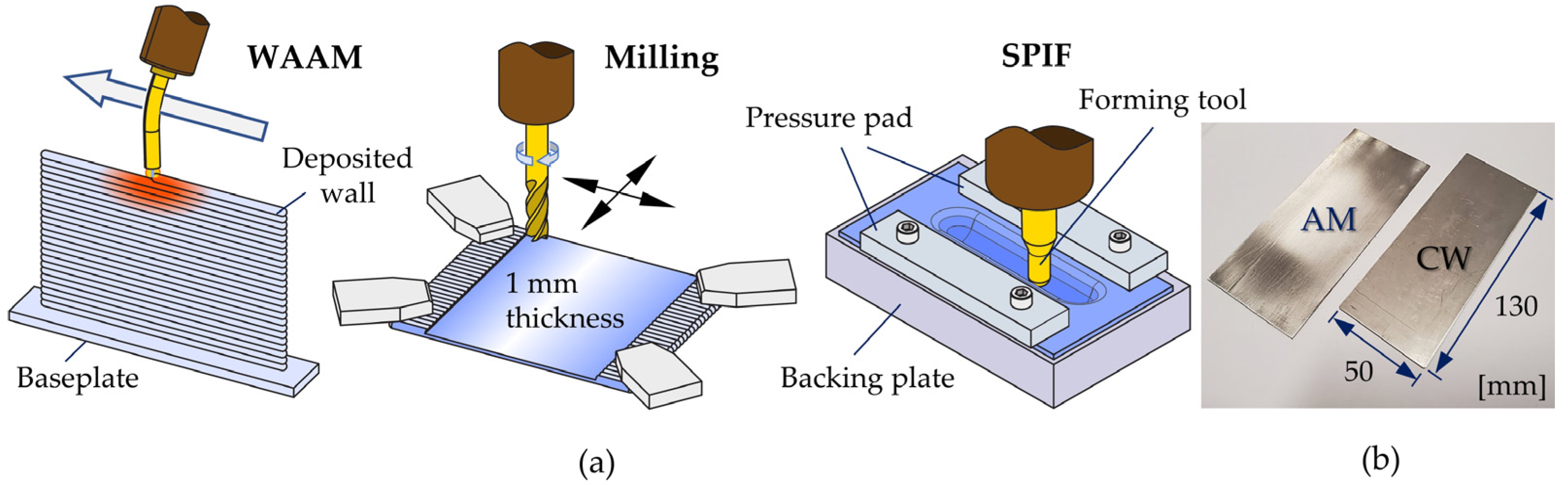
Under these circumstances, this paper is focused on the combination of wire-arc additive manufacturing (WAAM) and SPIF to produce stiffening grooves in thin metal parts. In a broader perspective, the work can also be seen as a first attempt to hybridize additive manufacturing with dieless incremental forming for the embossing of stiffeners, letters, numbers and decorative designs with moderate-to-high depths and thickness changes in the parts.
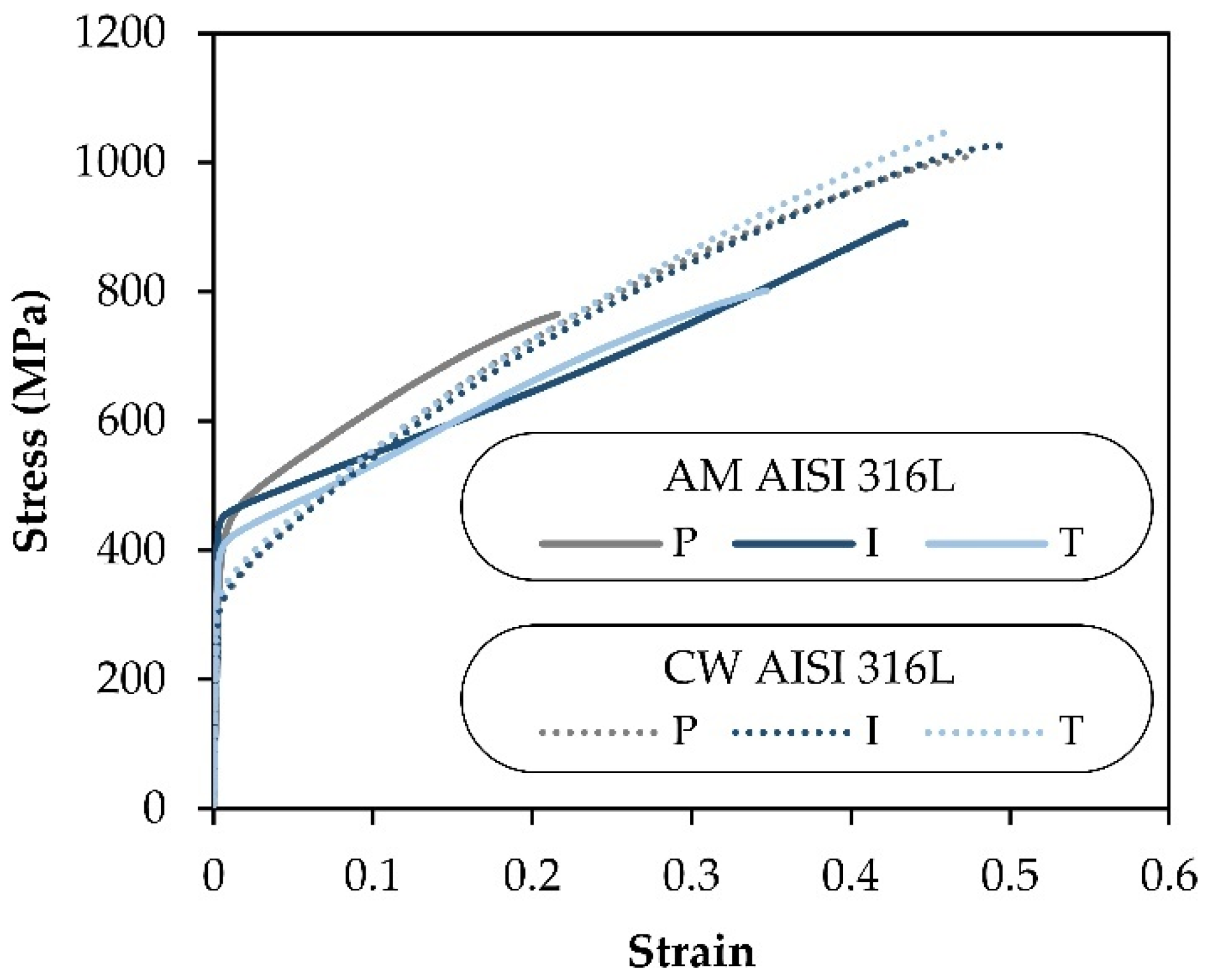
The work is performed in additively deposited stainless-steel sheets and includes a new analytical model to predict the force and the maximum admissible stiffening groove depth produced by SPIF. Wrought commercial stainless-steel sheets are included for comparison purposes and the overall results show that the proposed analytical model can be successfully used to characterize plastic deformation and failure by the tearing in hybrid additive manufacturing of stiffening grooves. Microstructure observations and anisotropy justify the differences in the mechanical response of the additively deposited and wrought commercial stainless-steel sheets, in agreement with previous observations of the authors in the same material [
14] and of other authors in different materials [
15].
3. Results and Discussion
3.1. Strain Paths
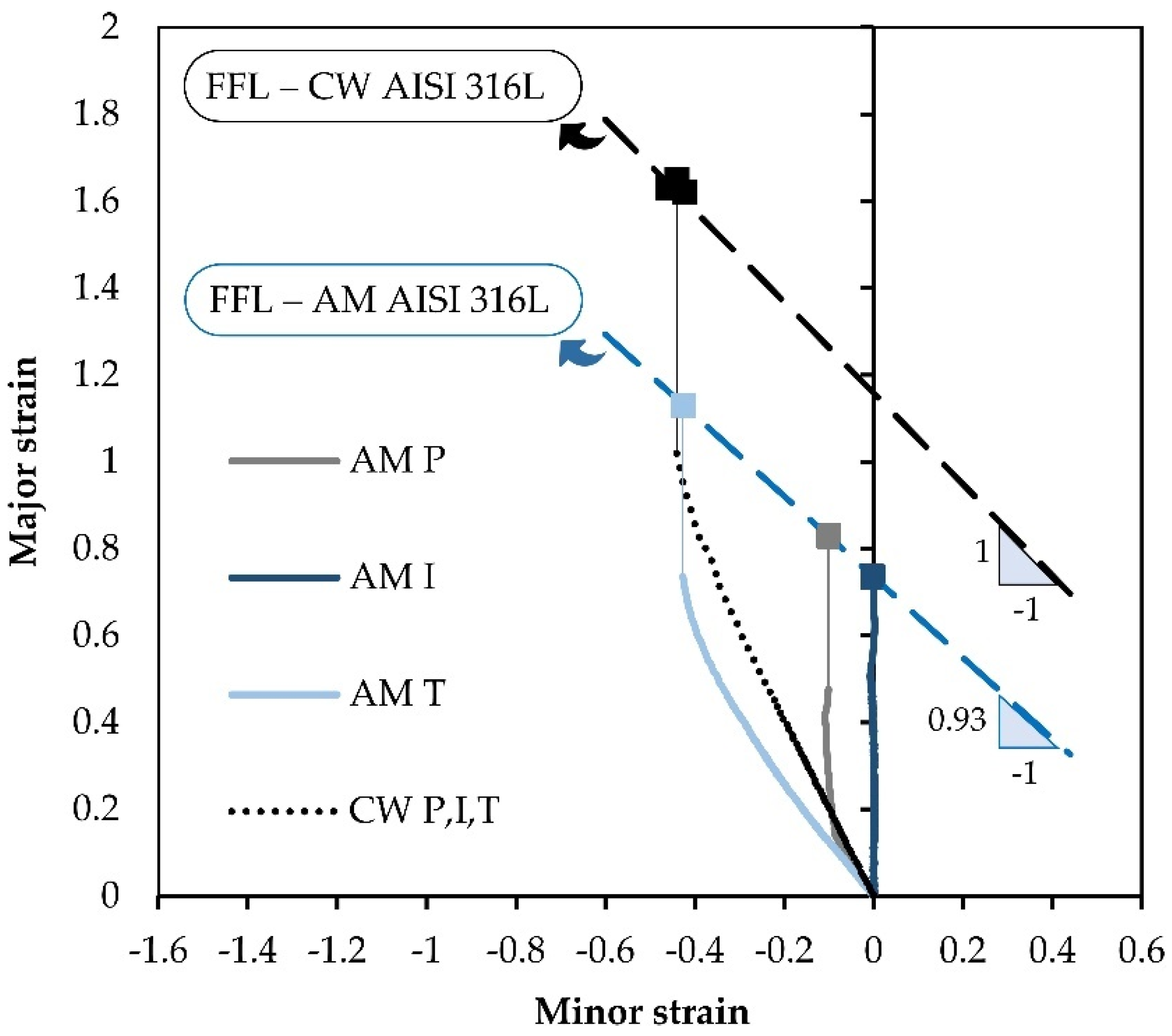
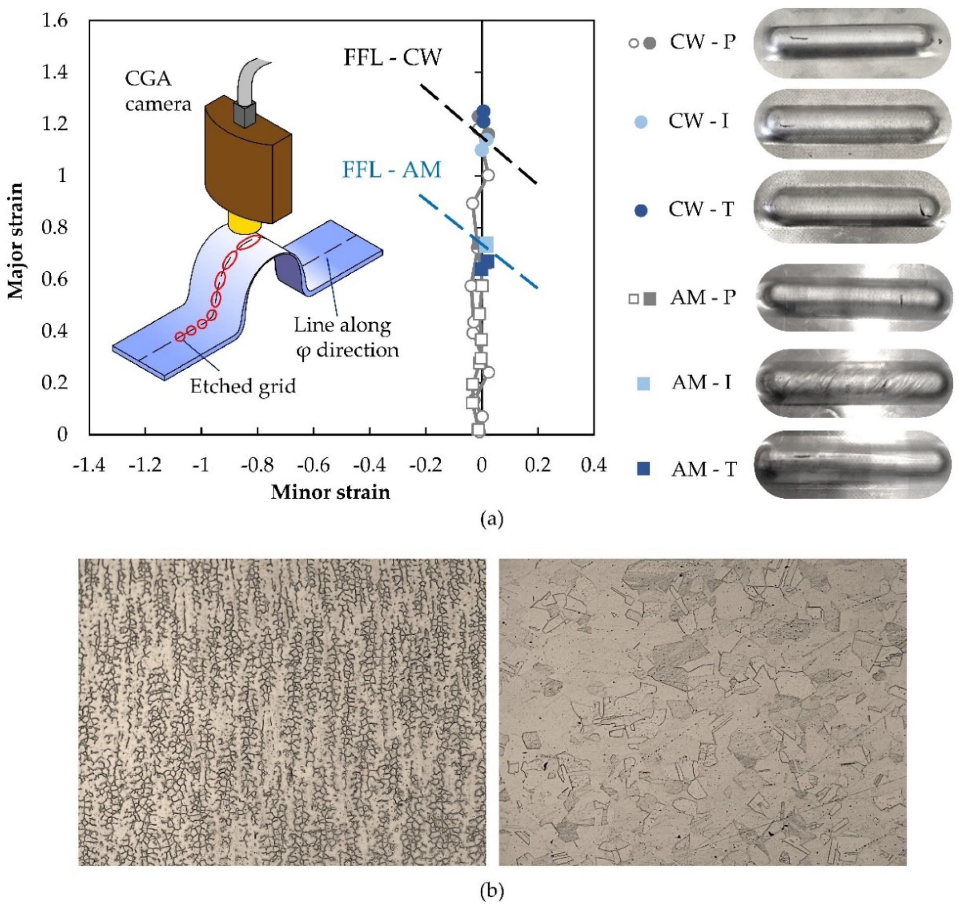
Figure 6 shows the experimentally measured strains along the perimeter of the grooves produced along the parallel (P), inclined (I) and transverse (T) directions with respect to the build or rolling directions for the additively deposited and wrought commercial AISI 316L stainless-steel sheets. The results were obtained for the instant of time immediately after tearing by crack opening and propagation along the longitudinal direction (i.e., tool feed direction).
As seen, all of the strains lie close to the vertical axis, in agreement with the assumptions of the material being subjected to plane strain deformation under linear strain loading paths (refer to
Section 2.2 and
Section 2.3). Moreover, the maximum strain values obtained from the circle grid analysis are also close to the FFLs of both additively deposited and wrought commercial sheets (
Section 2.1), which are plotted as dashed straight lines falling from right to left in principal strain space. This last result, obtained for the two types of sheets, allows for concluding that incremental forming of the grooves fails by critical thickness reduction without previous necking in close agreement with crack opening by tension (mode I of fracture mechanics) [
21].
Observation of the photographs included in
Figure 6a reveals that the surface of the grooves that were incrementally formed along the inclined direction of the additively deposited sheets contain a series of striations that coincide with the building direction (approximately 45° to the inclined direction). This type of texture is not visible in the corresponding specimen of the wrought commercial sheets and is attributed to the dendritic-based microstructure of the additively deposited sheets, which is made of columnar grains with primary arms aligned with the building direction and secondary arms bonding the neighboring grains together (
Figure 6b). This type of microstructure, which was previously observed by the authors in tensile tests [
14], is different from the equiaxial microstructure of the wrought commercial sheets and is the main reason behind the anisotropic behavior of the additively deposited sheets.
The last conclusion to be taken from
Figure 6 is that, despite the differences in the surface texture of the grooves produced along the inclined direction of the additively deposited sheets, the strains at the fracture are close to those obtained for the other grooves produced along the parallel or transverse directions. Therefore, in what follows, there will be no distinction between the results obtained from each specific groove direction.
3.2. Maximum Allowable Depths
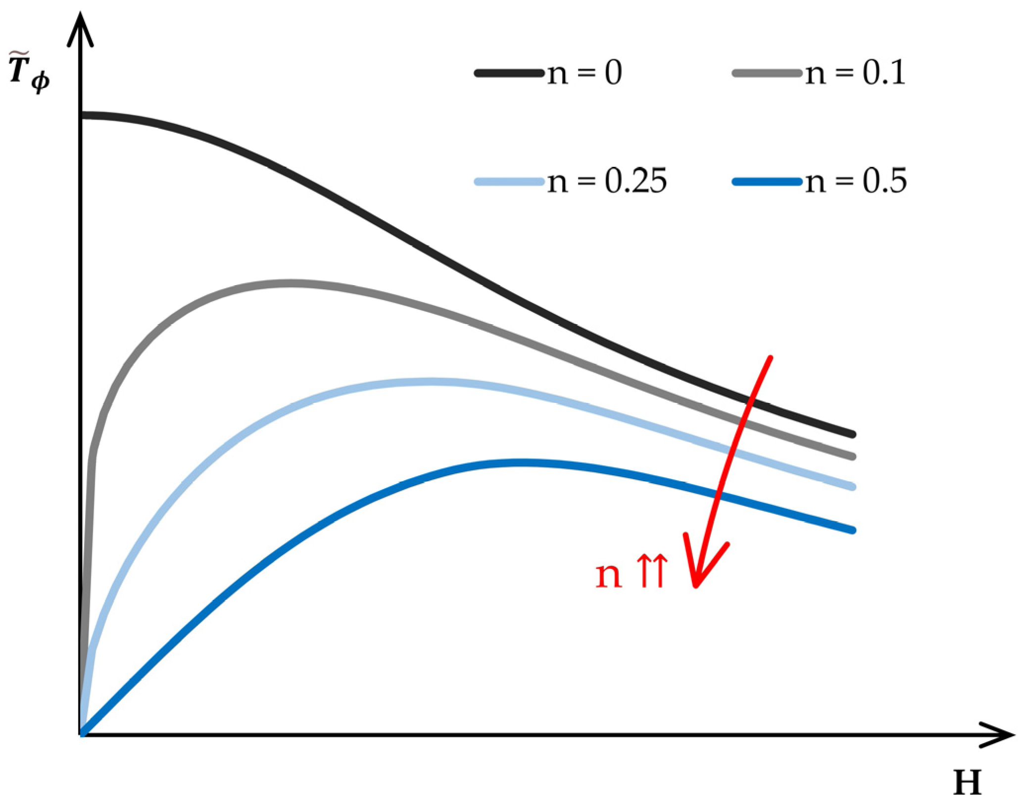
Figure 7 shows the theoretical evolution of the force per unit of length
(15) with the groove depth
for materials following a Ludwik–Hollomon strain-hardening relationship
, but having different values of the strain-hardening exponent
. To facilitate the comparison, it was decided to normalize the force per unit of length as follows:
where
is the constant of the Ludwik–Hollomon strain-hardening relationship.
As seen, the evolution of the normalized force per unit of length is very much influenced by the strain-hardening exponent , with peak values moving towards the vertical axis as the stress–strain response approaches that of a perfectly rigid–plastic material. In fact, when , the peak in the normalized force per unit of length occurs at the beginning of the process () because there is no material strain hardening to compensate the reduction in thickness that is inherent to the incremental forming process, and the normalized force per unit of length falls monotonically from left to right as the thickness decreases with the groove depth .
Increasing the strain-hardening exponent gives rise to evolutions of the normalized force per unit of length with growth and decay regions separated by a peak value. This means that strain hardening prevails at the beginning of the incremental forming process, whereas a reduction in thickness eventually leading to fracture prevails at the end of the process. The practical consequence of what was just said is that the identification of the maximum allowable depth by searching the force per unit of length value (15) that matches the critical value at the onset of failure by fracture (17) must only consider the decaying regions of the evolutions.
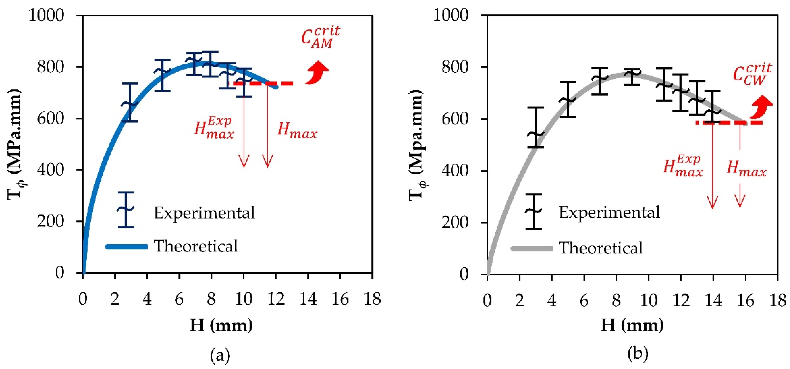
Transposition of above conclusion to the results obtained for the additively deposited and wrought commercial sheets that are depicted in
Figure 8 results in the rightmost intersections between the dashed horizontal lines corresponding to the critical values
at the onset of failure by fracture (17) and the force per unit of length evolution that is shown in the figure. The possible intersections on the left-growing evolution of the force per unit of length are discharged.
The maximum allowable predicted depths
resulting from the above-mentioned intersections correspond to an overestimation of the maximum allowable experimental depths
below 20%. The experimental points included in
Figure 8 serve only to validate the theoretical evolutions of the force per unit of length with the groove depth.
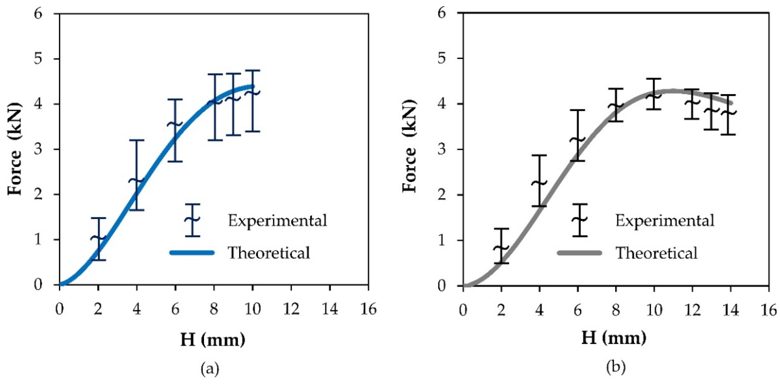
3.3. Tool Forces
Figure 9 presents the experimental and analytical evolutions of the tool force with the groove depth for the two different types of sheets. As seen, the analytical predicted evolution can replicate the overall trend of the experiments results but with a slight underestimation of the real values. The discrepancies are attributed to the overall assumptions of the analytical model, namely to the utilization of average instead of local values of the main variables, but also to some degree of uncertainty in defining the contact length
in the z-direction (
Figure 5), because it may include a part of the tool surface located behind the vertical symmetry axis.
Scattering of the experimental data is larger for the additively deposited sheets due to anisotropy and, consequently, to different stress–strain responses during the tests performed along different directions with respect to the build direction. In connection to this, it is worth remembering that wrought commercial sheets are roughly isotropic ().
All in all, the results show that a relatively simple analytical model based on a shell subjected to in-plane stretching can provide a good estimate of the tool forces.
4. Conclusions
Hybridization of additive manufacturing with single-point incremental forming can be utilized to produce stiffening grooves in thin sheets to improve their strength to withstand the efforts that are applied to them in service. Because out-of-plane grooves are not produced during material deposition, there is no need for using support structures to preserve the overall geometric integrity of the parts.
The estimates of the required force to produce a specific groove depth and of the maximum allowable groove depth that can be formed without tearing by means of a simple analytical model developed by the authors are in good agreement with the experimental observations and measurements. In particular, the results show that the maximum allowable stiffening grooves that can be produced in additively deposited AISI 316L stainless-steel sheets are approximately 27% smaller than those produced in wrought commercial AISI 316L stainless-steel sheets. This is due to anisotropy and to the lower formability induced by the dendritic-based microstructures resulting from the growth of grains along the temperature gradient during the heating–cooling cycles of material deposition.
Despite the above said disadvantages and limitations, the production of stiffening grooves in additively deposited thin sheets is interesting and feasible because grooves can undergo large plastic deformation before tearing.
Finally, it is worth mentioning that hybridization of additive manufacturing with single-point incremental forming to produce stiffening grooves can also be used in tubes, profiles and complex three-dimensional thin structures to improve their capability to withstand the different efforts that are applied to them in service.


 ,
, 


