1. Introduction
Unmanned and autonomous systems play an essential role in various fields—whether industrial, civil, or military—and experts of unmanned and autonomous systems have become integral members across diverse sectors, encompassing industrial, civil, and military applications, prompting experts from these domains to explore the multifaceted potentialities of task collaboration within heterogeneous robot systems. Heterogeneous robot systems refer to an assembly of robots that are diverse in terms of their functionalities, structures, and capabilities and are designed to work collaboratively towards achieving complex objectives [
1]. This consortium of assorted robotic platforms often includes a mix of unmanned aerial vehicles (UAVs) and unmanned ground vehicles (UGVs), among others, enabling a richer interaction and broader operational scope compared to homogeneous systems. The synergy within these heterogeneous systems strives to harness the distinct strengths and capabilities of each robot type, enhancing the overall efficiency, adaptability, and resilience of the collective in executing coordinated tasks or missions across varying environments. These fields continue to consider how to research the various possibilities of task collaboration within heterogeneous robot systems.
However, before the effective deployment of multirobot systems to perform complex tasks can be achieved, the research community still faces numerous fundamental technical challenges. These challenges, as listed in [
2], encompass areas such as big data, the Internet of Things, task complexity, autonomous machine learning, scalability and heterogeneity trade-offs, coalition formation and task allocation, human in the loop, transfer learning, unified frameworks, communication constraints, and connectivity uncertainty. In addition, there are complex application challenges outlined in [
3], including adaptive heterogeneous architecture and modeling methods for robot swarm systems; distributed perception and cognition of high-dimensional situations [
4]; intelligent decision making and planning of robot swarm systems that can be guided, trusted, and evolved; and autonomous collaborative control of robot swarm systems.
In recent years, significant advancements have been made in the fields of robot operating systems, unmanned system task planning, formation control, ad hoc network communication, and intelligent algorithms. The collaborative sensing of robot clusters primarily encompasses collaborative positioning technology [
5,
6], collaborative target recognition, multisource sensor collaborative optimization, and collaborative target tracking [
7]. Intelligent decision making and planning in cluster systems involve traditional methods such as the Hungarian algorithm, auction algorithm, particle swarm algorithm, and corridor-based methods [
8], as well as collaborative task networks constructed using machine learning models [
9]. The cooperative control of robot clusters has also seen extensive theoretical research on fundamental modes like consistency control, formation control [
10], and formation tracking control [
11].
When robots perform complex tasks, whether operating independently or collaborating in clusters, they require a simulation architecture for integrated testing and validation. Distributed simulation technology, owing to its characteristics, holds the potential to serve as the simulation verification scheme that most closely resembles the actual working environment of heterogeneous multirobot systems engaged in collaborative task algorithms. Past developments in distributed system technology have encompassed research on synchronization techniques based on message dialogue [
12], the implementation of flexible access technologies founded on active services [
13], and the provision of reliable operational support guarantees [
14]. These advancements have positioned distributed simulation as a viable approach to accurately simulate and verify collaborative task algorithms in robot clusters [
15,
16,
17], facilitating effective evaluation and testing in environments closer to real-world conditions. Through distributed simulation, it becomes possible to validate the collaborative behavior and performance of robots in complex environments while also assessing the robustness and reliability of robot systems. This contributes significant support and assurance for the rapid advancement and application of robot technology. In addition, there are many simulation systems that can also provide UAV operation simulation training when considering the way people control the loop [
18,
19,
20].
Based on the theoretical work of predecessors, we propose an open system simulation architecture. In this paper, we first list some relevant technical achievements that inspired our work and describe the progress they have made (see
Section 2). Next, we focus on introducing the architecture of the three-layer network simulation verification platform we propose for implementing collaborative algorithms of heterogeneous robot systems (see
Section 3). In the experimental section (refer to
Section 4), we delineate the experimental procedures and scenario designs. In the discussion
Section 5, we analyze network characteristics and provide reference suggestions for building similar architectures. Finally, in
Section 6, we offer some shallow insights into the study of collaborative networks.
2. Related Work
Over the past 25 years, robot simulation platforms have evolved almost simultaneously with robotics (see
Table 1). Initially, research and development enterprises of robot hardware platforms provided simulation modules that could be integrated into Simulink, enabling users to facilitate secondary development. Meanwhile, the complexity of robot structures increased, leading to a wider range of tasks. As robot diversity expanded, the modeling complexity also grew higher. Consequently, a single module could no longer meet user demands, and independent simulation software began to emerge in collaborations between enterprises and universities [
21,
22,
23,
24].
Subsequently, as feature engineering and other multisensor fusion technologies advanced, simulation platforms not only had to provide basic dynamic simulation but also had to simulate digital signals from multiple sensors, such as visual cameras (even infrared), LiDAR (light detection and ranging) in [
23,
25,
26], and SONAR (sound navigation and ranging) in [
27], allowing for a comprehensive and realistic representation of the robot’s perception capabilities in the virtual environment. Fast-forward to the past five years, and with the progress of artificial intelligence technology, simulation platforms have found greater utility in providing training samples. This utilization leverages efficient training mechanisms offered by emerging learning algorithms, thus enabling robots to perform better on many nonlinear problems [
28,
29].
Table 1.
A representative series of simulation platforms for robot systems.
Table 1.
A representative series of simulation platforms for robot systems.
| First Published Year | Institution | Software * | Tool | Render | Dynamics | Sensors | Vehicles |
|---|
| 1998 | Swiss Federal Institute
of Technology in Lausanne [21] | webots | OpenGL | ODE | IMU, RGBD | Robots |
| 2001 | Simon Fraser University [30] | Stage | FLTK | OpenGL | – | IMU, RGBD | Robots |
| 2007 | University of California
and University of Pittsburgh [31] | USA RSim | Unreal Engine 2.0 | ODE | IMU, RGB | Robots |
| 2008 | Coppelia Robotics | V-REP | OpenGL | ODE, Bullet Physics,
Newton Dynamics,
Vortex Physics Engine | IMU, RGB, LiDAR,
sonar, GPS | Wheeled robots, tracked robots,
four-wheel drive vehicles,
aircraft |
| 2010 | Carnegie Mellon University [32] | OpenRave | OSG | IKFast | IMU, RGB | Robotic arm |
| 2011 | Free University of Brussels [33] | ARGoS | Qt-OpenGL | ODE
Chipmunk | IMU, RGB | Robots |
| 2012 | Universitat Jaume I [27,34] | UWSim | OSG | osgOcean | Bullet | IMU, RGB, sonar | Underwater robots |
| 2013 | Technical University of Darmstadt | Hector | Gazebo (ROS) | OpenGL | ODE | IMU, RGB | Drones |
| 2016 | University of Zurich
ETH Zurich) [35] | RotorS | Gazebo (ROS) | OpenGL | ODE | IMU, RGBD | Drones |
| 2016 | OpenAI [22] | OpenAI-Gym | Gym | Mujoco [36] | IMU | Multijoint robot |
| 2017 | Inter, Toyota, etc. [37] | CARLA | Unreal Engine | PhysX | IMU, RGBD | Ground vehicles |
| 2017 | MicroSoft [23] | Airsim | Unreal Engine | PhysX
fastsim | IMU, RGBD,
Segment, LiDAR | Drones,
ground vehicles |
| 2019 | MIT [38,39] | FlightGoggle | Unity | - | IMU, RGBD, Segment | Drones, ground vehicles |
| 2020 | University of Texas and Stanford University [40] | robosuite | mujoco-py | OpenGL | Mujoco | IMU, RGBD | Robots |
| 2020 | National University of
Defense Science and Technology,
Beihang University, etc. [41,42] | XTDrone | Gazebo (ROS) | OpenGL | ODE | IMU, RGBD | Drones, robots |
| 2021 | University of Zurich and ETH Zurich [43] | Flightmare | Unity | - | IMU, RGBD, Segment | Drones |
| 2021 | Stanford University [44] | IGibson | Unity | - | IMU, RGBD,
Segment | Drones |
| 2021 | Beihang University and
Central South University [45] | Rflysim | Unreal Engine | CopterSim | IMU, RGBD | UAV |
| 2021 | Nvidia [24] | Issac Gym | Issac Gym | PhysX | IMU | Bipedal robot,
robotic arm, etc. |
| 2022 | University of Hong Kong [25] | MARSIM | ROS | OpenGL | - | IMU, LiDAR (HD) | Quadrotor |
| 2023 | Institute of Automation,
Chinese Academy of Sciences [26] | NeuronsGym | Unity3D | - | IMU, LiDAR | Mecanum wheeled robot |
| 2023 | Cosys-Lab (FTI) of
University of Antwerp, Chinese Academy [46] | COSYS-Airsim | Unreal Engine | - | IMU, LiDAR, RGB | Drones, ground vehicles |
These systems provide platform support for research, learning, testing, and validation of control, perception, navigation, and adversarial tasks. Driven by application requirements, the development of robot simulation technology has been continuously progressing. It has evolved from simulating single objects to multiple heterogeneous objects, from simple static environments to complex environments, and from cooperative collaboration to adversarial games. In addition, the scale of software has been growing increasingly large.
The previous approach of simulating and accessing multiple controllers on a single computing terminal is no longer sufficient to meet the demands. A distributed simulation architecture is needed to address the challenges of scalability. Therefore, our task is to propose a scalable distributed multirobot collaborative simulation architecture to meet the growing demands for functionality and complexity.
Furthermore, the distributed nature of the simulation architecture possesses an inherent advantage: it more accurately reflects the communication characteristics present in real-world working conditions, regardless of whether the multirobot system employs centralized or distributed collaborative algorithms. This advantage underscores the significance of utilizing a distributed network structure for deploying multirobot systems.
3. Architecture for Digital Battle
Drawing on the design experience of control and perception modules from related works, and taking into account the coordination of multirobot systems at the information level as well as the coupling relationships in kinematics, dynamics, and other aspects, we formally propose a three-tiered distributed simulation architecture tailored for heterogeneous multirobot collaboration.
Taking into consideration the potential complexity associated with the collaborative operation of heterogeneous robot systems, we adopted three fundamental principles in our design approach:
- i
The simulation process and outcomes must adhere to the laws of physics, ensuring their consistency across distributed simulation nodes;
- ii
The capabilities of each robot’s motion platform are determined by the structural design, accessory selection, and control implementation;
- iii
The collaborative algorithms employed in heterogeneous robot systems should be validated through authentic distributed verification methods.
According to these three designing principles, we propose an architecture to organize models and algorithms by three key layers (
Figure 1):
- (1).
Distributed virtual simulation network layer.
It is mainly aimed at maintaining a unified virtual world for every distributed participant. As most massively online role-playing games have employed, a popular technical solution is a client–server(C/S) network, where the clients keep a local copy of the virtual world, and the server keeps the authority of the simulation with the responsibility for four services, viz. physical interaction, scenario management, synchronization service, and session management.
- (2).
Perception and control subnetwork layer.
We retained many of the advantages of Airsim’s solution [
23]. This subnetwork connects the virtual avatar with its bonded “brain” (i.e., the one that possesses the control). The virtual avatar could be a motion platform with actuator and sensor units, while the “brain” could be a mature hardware with an RTOS (real-time operating system), a set of algorithms, or even a person, i.e., the subnetwork could work either in the artificial intelligence mode or the human-in-the loop mode.
- (3).
Collaborative communication service network layer.
As has been proven to be a success in real-time distributed embedded systems, the idea of a data distributed service (DDS) [
47] is also adopted here to provide a basic information transmission mechanism. It is believed to support most of the possible collaborations between the upper compute node of heterogeneous robot systems.
As a distributed system, the startup process of simulation is a bit cumbersome. There are two primary constraints on the startup order: (1) The distributed virtual simulation network server should launch before other clients participate. (2) The perception and control subnetwork can only establish the connection between the avatar and the “brain” after the virtual character (i.e., the avatar) has been created in the virtual world. In addition, the collaborative communication service network can work whenever a “brain” is online. Next, more details about these three key layers’ services are described.
3.1. Distributed Virtual Simulation Network
To assure all the participants feel like staying in the same virtual world, the distributed virtual simulation network provides a series of easy-to-use C/S services. Among these services, session management only deals with the long-term connection mechanism for virtual clients and servers (
Figure 2), while scenario management, physical interaction, and the synchronization service work together to coordinate processing related to simulation content on distributed platforms.
3.1.1. Session Management
From the perspective of distributed simulation, session management is the functional basis for the server–client architecture connection [
48]. The essential functions provided mainly include providing an available port when creating simulation services on the server side. The client discovers and joins the server side in the network, providing role selection and publicity of virtual robot system objects for specific simulation tasks.
The entire distributed simulation session is divided into three stages (
Figure 3): (1) At the beginning After creating and joining a simulation session, the server controls all participating clients’ entry into the their local simulation map synchronously, generates corresponding virtual objects at the starting position set in the scenario management, and obtains control permissions over them. (2) During the process. During the simulation, session management provides continuous connection support for data synchronization between the server and the client. This synchronized data contain individual dynamic objects in the scene, as well as robot system entities controlled by the client. (3) At the end. After the distributed simulation task ends, the clients exit the server-managed session and end all data services. All these features are customizations of and upgrades on the mechanics of the game engine’s multiplayer sessions.
3.1.2. Scenario Management
Like most simulation systems and virtual games, the scenario usually defines a global coordinate system in virtual space (either in a local three-dimensional Cartesian coordinate system or using spherical coordinates of the Earth), initializes various entity objects in that coordinate system, and manages every simulation-involved object, e.g., landscape, buildings, roads, nonplayer characters (NPCs), robotics under control, and even the wind field.
As shown in
Figure 4, scenario management is mainly a matter of storage and calculation.
The difference is that the server updates a global scenario, while clients only act on local space.
- (1).
On the server.
Based on the fundamental understanding that the server possesses superior parallel computing and memory read/write capabilities, it is responsible for maintaining global scene information. When receiving a request from a client to update object properties in the scene, the server first checks for potential conflicts, then determines the multicast node list based on the activity level of each client involved in the update, and finally distributes the update results to the respective clients.
- (2).
On the client.
The client-side scene management loads local object data according to the specific requirements of each client. There are three main categories for handling object data: (1) objects closely related to the controlled objects are stored in a cache for efficient access and support dynamic calculations at higher frequencies; (2) objects that are not directly affected by the client, but require awareness, are kept in memory and synchronized with the server’s replication commands; (3) unrelated objects are set to an inactive state and remain stored on the hard disk as a resource.
3.1.3. Physical Interaction
Inspired by Mujoco’s state-of-the-art performance in contact dynamics [
36], we believed it is worthwhile to provide an interaction mechanism to support similar calculation on our distributed platform. Commonly, interaction calculation has three key steps:
Since a certain interaction must be triggered by some specific condition, we might as well define the conditional function
as in Equation (
1). For arbitrarily selected objects
and
with generalized state parameters
and
, the positiveness of function
can indicate whether the interaction conditions are met. Mathematically, function
is a binary relationship.
A graph
can describe the interaction relations within objects [
49]. The vertex set
and the edge set
construct an adjacency matrix, with each element
,
(For those discrete event-driven interactions that can be linearly separated into pairs, skip directly to step 3.)
For those relatively complicated cases, instead of listing various kinds of interaction models in detail, we use standard Hamiltonian systems as a theoretic representative of multi-rigid-body dynamics [
50]. Suppose there exists a connected subgraph
(i.e.,
,
and the derived distance matrix
of
, s.t.,
there is
). This subgraph
illustrates the object set
as isolated from other objects by distance
l. The edges in
and the corresponding constraints determine a tangent bundle (i.e., configuration space) spanned by the objects in
, e.g., along with the constraint, [
51]
The constrained forces, subject to the D’Alembert–Lagrange principle, define the virtual displacements
and constrained forces
where there would be
, and also with the assumption that multi-rigid-body problem is subject to the Hamilton’s principle of least action.
The motion equation is the cotangent bundle in Equation (
5), where
refers to the combined force of the input driving force and the possible dissipative force [
52,
53,
54].
If the expression in Equation (
5) is separable, the explicit differential expression could be constructed easily [
55], but for those implicit issues, the construction method depends on the area of the problem and is beyond the scope of this article.
Suppose we already have an explicit expression pattern Equation (
6) for every object involved in the interaction subgraph
. The evolution of the isolated interacted system can be figured out and updated for every distributed client.
3.1.4. Synchronization Service
A synchronization service is the key to maintaining limited consistency for each node in a distributed virtual network.
Figure 2 shows two paths for synchronization, namely, emergent frame and state update.
- (1).
Emergent frame.
In objects with coupling relationships (e.g., constraints on the state), if there are more than two related clients, emergent frame is the event-driven way to reconstruct the motion model on the related clients. This specific method is based on the remote procedure call (RPC) mechanism, and the server triggers the response of the relevant client to reconstuct the motion model (i.e., step 2 in the physical interaction).
- (2).
State update.
It is a cycle-adaptive multicast method. The client will detect whether the properties of the local object change for every time interval and send a synchronization request to the server if they change. The server accepts the request and confirms that it is valid and then packages the object of the application attribute change in the next state synchronization frame and synchronizes it to the relevant client according to the multicast list. The selection of time intervals is positively correlated with the number of occurrences in other client local zones and does not exceed the upper limit allowed by the network. Assuming that all properties with amount
D are recognized as needing to be synchronized to other
clients within the synchronization allowable time
, the supremum of the state update network traffic as stream
can be inferred as
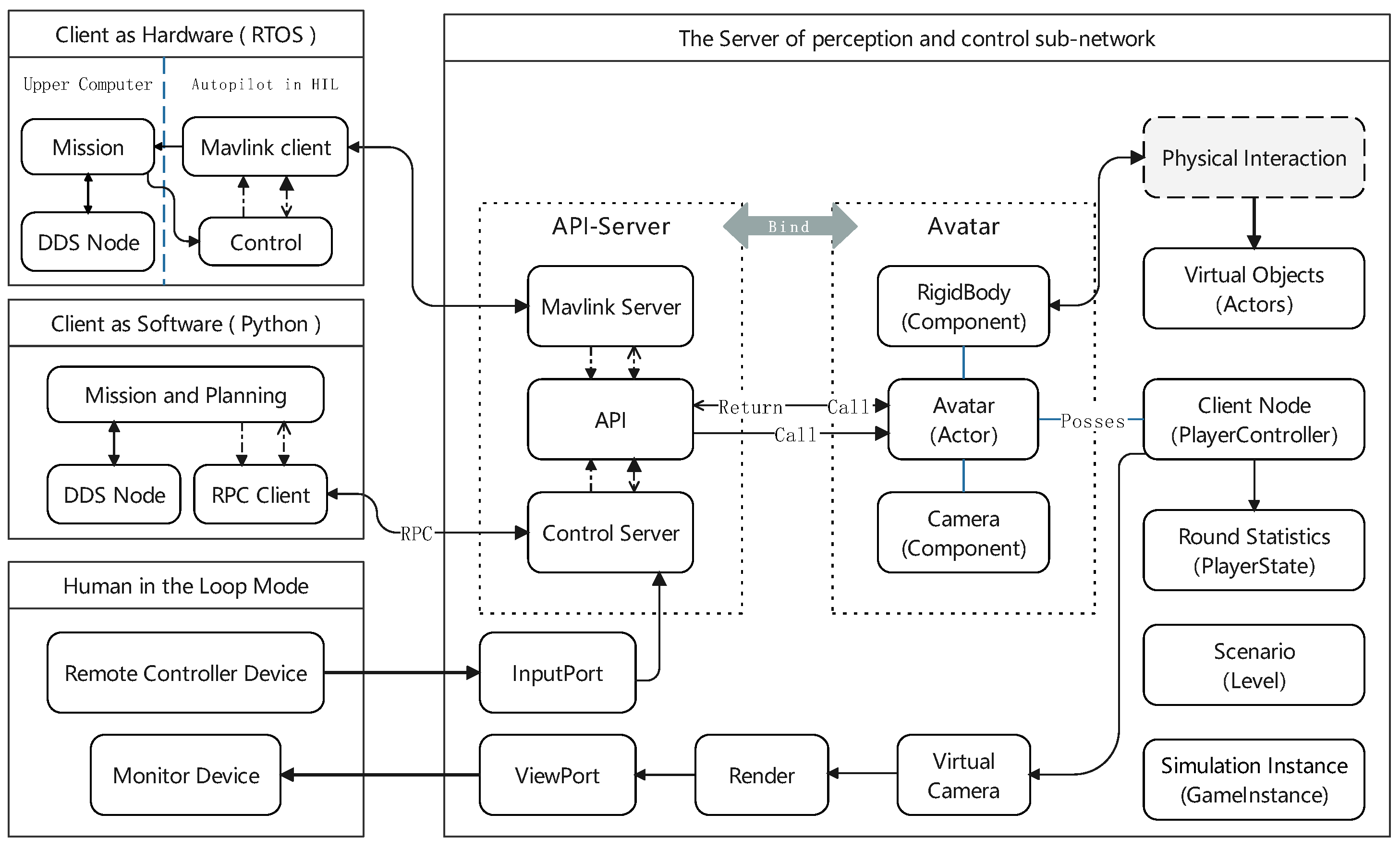
3.2. Perception and Control Subnetwork
The perception and control network is a one-to-one network abstracted from Airsim [
23]. Sensor data, actuator signals, perception data, and the desired state can either use the Mavlink protocol to connect the algorithm hardware and the virtual client (
Figure 5) through the serial port or use remote procedure call (RPC) locally to realize the interoperability between the algorithm software and the virtual client or access the user through the peripheral of human–computer interaction.
Unlike the other two-layer networks, the perception and control subnetwork is an independent connection mechanism, which only requires the baud rate of the local hardware interface or the read/write rate of interprocess communication to meet the bandwidth requirements of state data and control instructions.
3.2.1. Artificial Intelligence Mode
The simulation verification subject for this platform’s design is the robot system’s planning and control algorithm. For clients in artificial intelligence mode, algorithm access methods are mainly divided into hardware in the loop and software in the loop.
Since the update frequency of sensor data and control data is fixed, it may as well be set up where
is the size of the
ith datum and
is the corresponding update frequency. Thus, the average traffic on the perception and control subnetwork is
- (1).
Hardware in the loop.
Thanks to the contribution of the open-source community, we can directly integrate Mavlink support into the hardware in the loop and enable autonomous driving hardware to drive the corresponding robot system in the virtual environment. The hardware in the loop is usually transmitted through the serial communication interface at a negotiated baud rate and the actual effective bandwidth appropriate to Equation (
8).
- (2).
Software in the loop.
The simulation of software in the loop, based on the interprocess communication mode, connects the input and output of the artificial intelligence algorithm with the request and service form of remote process call, and the artificial intelligence algorithm is responsible for environmental perception, task decision making, action planning, and specific control node function implementation and the organizational framework and is not limited by the three-layer distributed simulation system architecture of this paper, as long as it meets the process communication rate constraints of the local perception-control loop.
3.2.2. Human-in-the-Loop Mode
The human-loop mode provides two possibilities for use. One is to directly send the input of the remote control handle of the human as a command signal to the API end of the robot system, which is a form of human–computer interaction with direct control; second, the client operator exists in the digital space as an avatar, which is aimed at verifying the collaborative mode of human–machine symbiosis.
The direct control mode is mainly connected to the operation control in the serial port mode of the controller simulator, and the human–computer symbiosis mode is realized through OpenXR access to VR or AR human–computer interaction devices.
3.3. Collaborative Communication Service Network
Different from the distributed virtual simulation network’s primary–secondary structure and perception and the control subnetwork’s one-to-one structure, the collaborative communication service network is a decentralized and completely flat distributed structure. For this design purpose, we use FastDDS (version >= 2.14) as the communication middleware for this layer of the network.
However, from the perspective of simulation construction, it is worth noting that the collaborative communication service network and the distributed virtual simulation network share the physical bandwidth of the network, but generally speaking, the application’s use of bandwidth is closely integrated with the collaborative problem itself, and we can only give an estimate of the bandwidth usage margin.
Assuming that the actual maximum bandwidth available to the network is
W and the distributed virtual simulation network utilizes
bandwidth in Equation (
7), thus, we have,
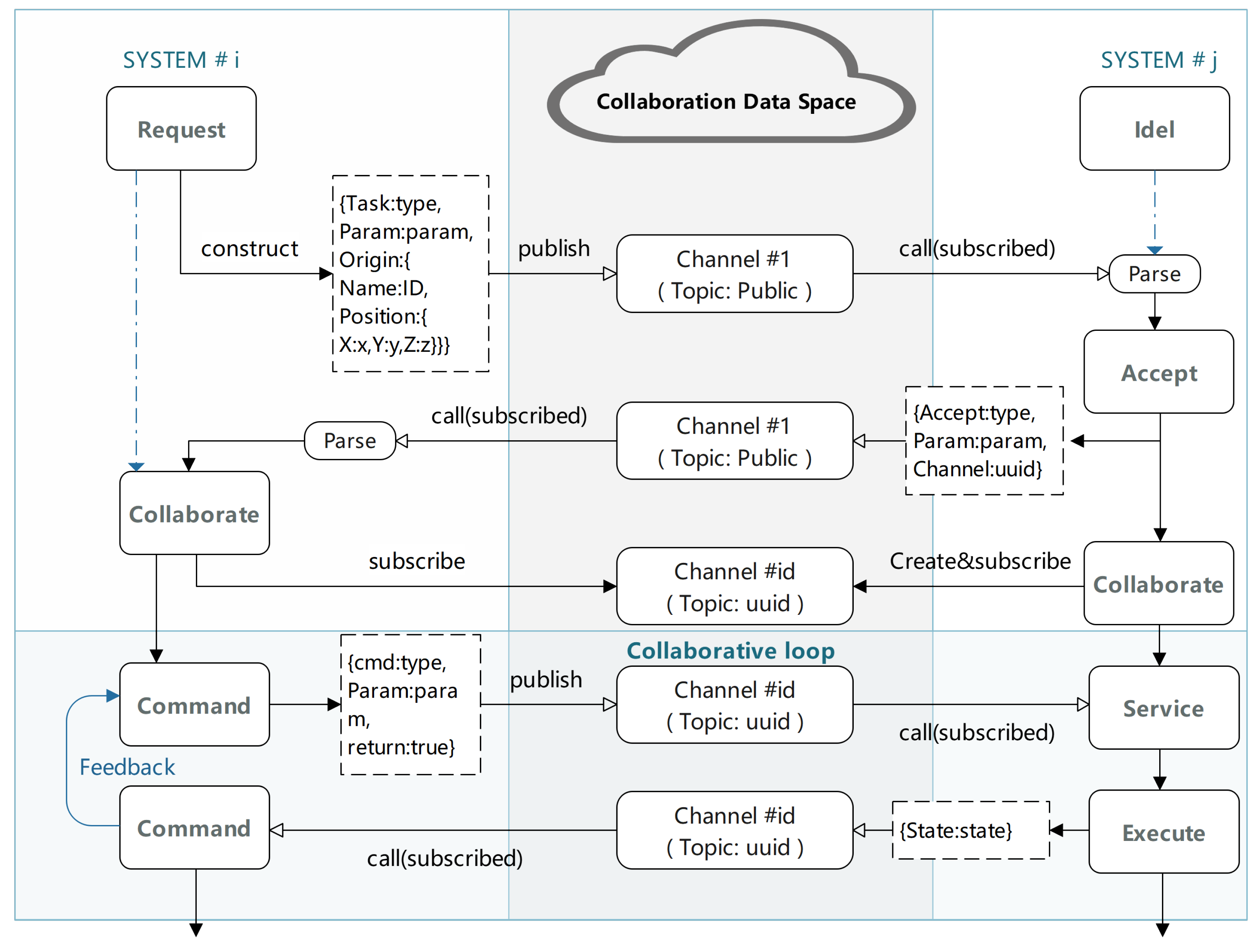
3.3.1. Basic Communication Mechanism
As in
Figure 6, DDS enables all intelligent algorithms of robot systems in a virtual scene to connect to the same publish/subscribe network. In the collaborative data space of the network, each topic can be regarded as a communication channel, and the nodes related to the topic in the network will subscribe to the topic corresponding to the channel and publish collaborative information to it as needed. The specific publishing process is as follows: first, encode the collaborative information according to the standardized JSON format, then serialize it into a string, and finally, publish it to the topic. It is possible to transform a data-centric DDS network into a task-centered collaborative network through the above mechanism.
3.3.2. Distributed Collaboration Process
This article provides an interop protocol process based on the above communication mechanism. Think of a collaborative task simply as a diagram of activity (
Figure 7) between two entities that request and respond together (see another work in [
56]). The public topic refers to the channel that all intelligent systems will subscribe to, mainly for requests and responses for collaborative tasks. When the requester and responder of a task match, create a dedicated task channel for continuous collaborative communication requirements.
In some special cases, it may not be necessary to form a dedicated topic channel, and when the coordination requirements are matched and confirmed, the task parameters will be sufficient to guide the jth cooperative system to complete the corresponding operation.
4. Example and Experiments
Based on the three-layer distributed simulation architecture, the performance test process is roughly divided into four steps:
- 1.
Design a virtual scene, define the coordinate system in the scene, place buildings and roads, and set the initial generation position of the robot system;
- 2.
Connect the computing platforms to the network, and specify a server and multiple clients among them, as well as setting the corresponding avatars (UGV or UAV) with their collaborative tasks.
- 3.
Start the simulation service and record the network stream frames at the same time with an improved network profiler;
- 4.
Analyze the distributed data service and compare the theoretical estimation.
Note: Any entity or logical object will be instantiated as a subclass of the actor when the experiment is implemented. Therefore, actors will be used as a general term when analyzing and describing results.
4.1. Scenario Description
The scene map covers an area of about 1 square kilometer, and the mission area is a village located in the desert hills, surrounded by mountains on three sides, with residential buildings scattered and arranged, with an average floor height of 20 m, and a two-lane road running through it. According to preliminary reconnaissance, the command post of a group of terrorist organizations is roughly located in the area enclosed by the black-and-blue wire frame in
Figure 8.
The enemy is in a rough position surrounded by a quadrilateral, and troops are deployed in the area as follows: a small building (commander on the second floor), 2 guard towers (snipers), and small groups of enemy troops (machine gunners and riflemen) patrolling the ground. The objective of the mission is to eliminate the enemy forces in the area as quickly as possible.
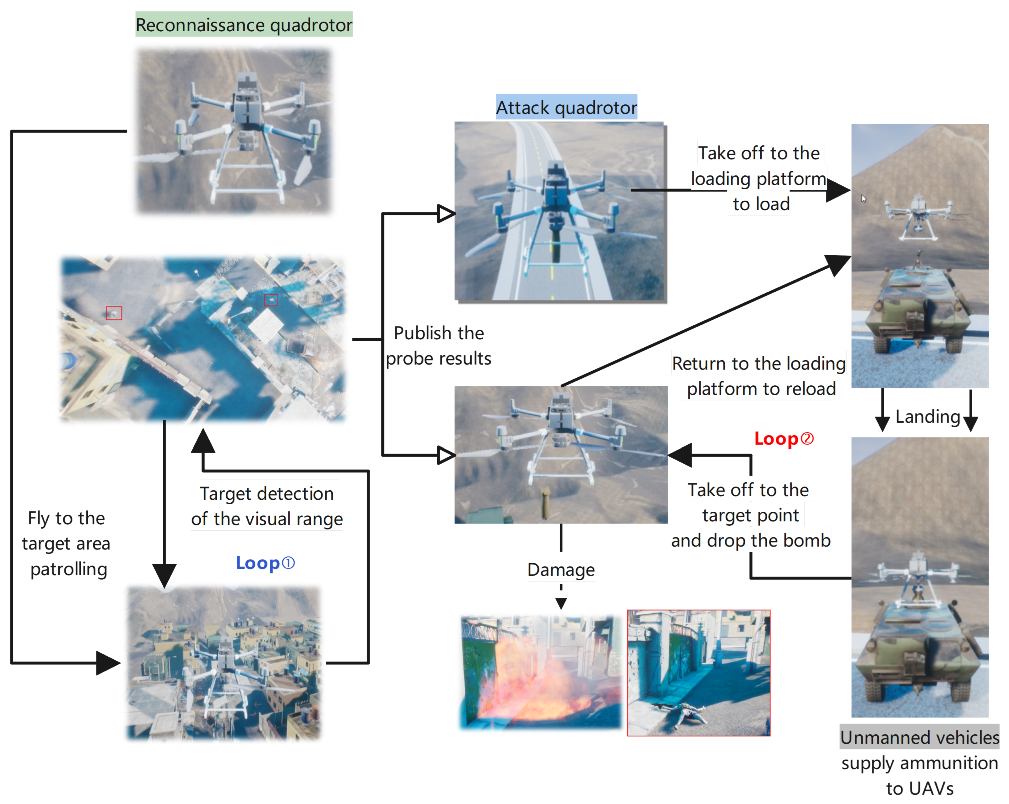
4.2. Collaborative Tasks
The cyclic execution process of two typical types of collaborative tasks (
Figure 9) is as follows:
- (1).
Target-Detection–Bomb-Strike Loop:
Within this loop, the reconnaissance quadcopter is responsible for detecting potential targets, and once a target is confirmed, the attack quadcopter executes the bomb-strike action. The reconnaissance quadcopter employs its sensor system to identify and locate the target and subsequently communicates the relevant information to the attack quadcopter. Upon receiving the information, the attack quadcopter promptly responds, launching a strike on the target and carrying out the bomb attack.
- (2).
Bomb-Attack–Ammunition-Supply Loop:
In this loop, after executing a bomb strike, the attack quadcopter requires replenishment of ammunition in order to continue its mission. The armored unmanned vehicle serves as the provider of ammunition, transporting the required ammunition to a designated location based on the needs of the attack quadcopter. Once the ammunition resupply is completed, the attack quadcopter can proceed with the next round of bomb strikes.
Through the implementation of such cyclic execution processes, effective coordination between the reconnaissance quadcopter and the attack quadcopter, as well as between the attack quadcopter and the armored unmanned vehicle, is achieved, facilitating efficient and synchronized combat operations.
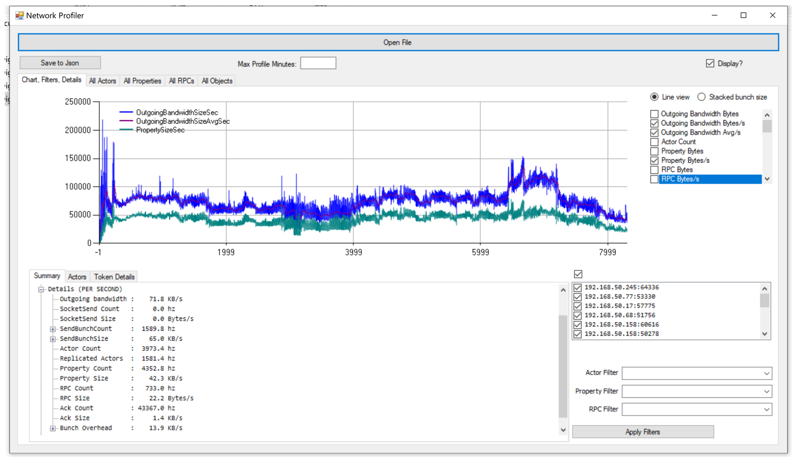
4.3. Sampling Software
In this subsection, we explore a valuable addition to the software (
Figure 10): a new feature module that enables users to output network traffic and performance information in batches to JSON files. Although this enhancement does not change the usage method, it greatly simplifies subsequent data processing, making analysis and optimization more efficient.
- (1).
Introduction to relevant functions:
Network Profiler is an independent tool designed to display network traffic and performance information captured by the engine during game runtime. This tool is highly effective in identifying areas of high bandwidth consumption in multiplayer games, allowing users to view the percentage of bandwidth occupied by various actors, PRCs, and attributes, thereby assisting in optimizing network performance.
- (2).
Recording and analyzing sessions:
Before using Network Profiler, users need to record the relevant data for analysis. Recording can be achieved by enabling the engine’s process-tracking feature, typically by compiling the engine into a debug build or using an editor build for nondebug configurations. Additionally, users can control the recording of network data by adding the command line parameter "networkprofiler=true" at engine startup or using other command line instructions.
The recorded data will be saved to the specified path, allowing users to open the file in the standalone tool for further analysis. It is important to note that temporary files will be renamed according to a specific scheme when the analysis session ends, facilitating accurate tracking and data processing.
5. Discussion
From the previous Introduction, our framework provides virtual simulation session management in C/S architecture, a basic perception and control logic framework, and a flexible configuration collaboration mechanism. We compare these three features with existing software in
Table 2. We compared simulation software for multirobot collaboration and found that the highlight of our work was the ability to manage state synchronization and coupling calculations for multiple clients using a session mechanism. Therefore, we discuss the characteristics of entity synchronization, bandwidth characteristics in the time domain, and the relationship between bandwidth and the number of clients in combination with experimental measurement data.
5.1. Actor–Synchronous Feature
This part of the experiment mainly examines different actors’ actual replication frequencies and replication times during synchronization. One UAV and two UGVs were set up for each of the three clients, and nonplayer characters that could track moving actors were also set up in the scene. The drone just received the hovering instruction while the UGVs are driven along the road by joystick.
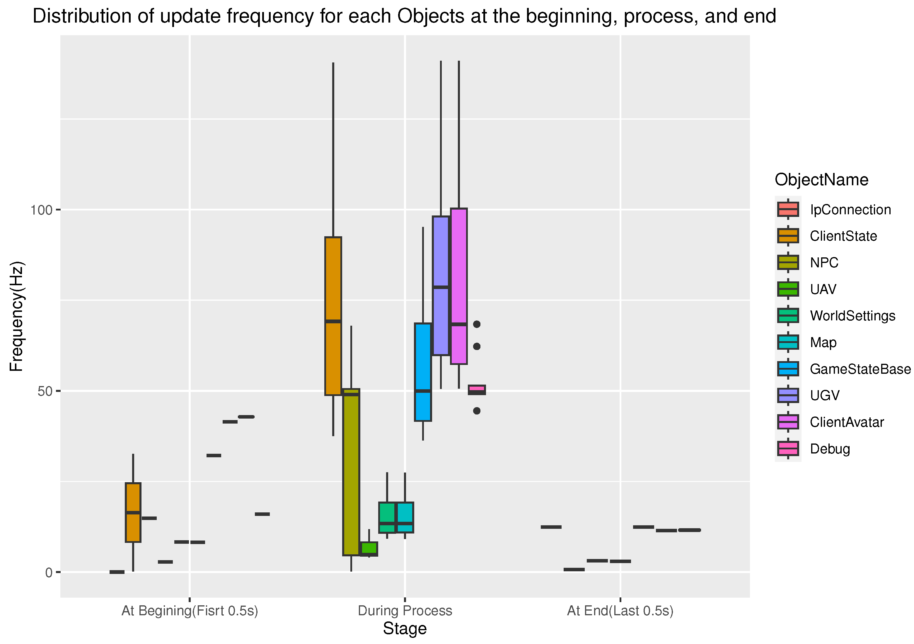
The results of the data visualization are shown in
Figure 11. The plot records the distribution box plot of the replication frequency of each actor that triggered the overall data change of the simulation at the beginning, during the process, and at the end of the simulation. Since the drone was only controlled to hover, the state change was moderated, and the update frequency was slow (merely 10 Hz). The UGVs were constantly moving, so the update frequency was high (always more than 75 Hz). Nonplayer characters were stationary or patrolling for a period because they could not see moving vehicles, so the median was very close to the upper quartile (about 50 Hz). In addition, object name sorting was performed from the smallest to the largest amount of data synchronized throughout the simulation.
For the resulting data of the same experiment, we also analyzed the replication time distribution when different actor states were synchronously managed to replicate to remote clients, and the visualization results are shown in the ridge-line plot (
Figure 12). Actors representing motion entities had a shorter replication time overhead because their state descriptions were relatively single and were usually state vectors of rigid bodies. They could usually complete the replication of states within 0.03 milliseconds, which could meet the time interval allowed for frame synchronization. The peaks in distribution roughly indicated several independently updated states or events for that actor.
5.2. Time Domain Analysis
In this part of the experiment, the goal was to test the data bandwidth and total throughput of as many clients as possible based on existing lab resources and to examine the correlation between data frames and state data. We built a server (Intel i9 with 32 GB memory) and invited 12 students to participate. They provided their laptops as clients (computer models and configurations were diverse) and their wisdom to design collaborative tasks, and we finally formed 15 distributed client nodes (some students were single-machine multiopen clients) to complete the distributed simulation experimental process. The duration of the simulation was less than 240 s.
Figure 13A provides an intuitive picture of the bandwidth occupied by the data frame, where the packet was initially used to complete the configuration work required for initialization on the distributed network. The data frame monolith was significant, but the synchronization frequency was relatively low. In the intermediate process, the data frame was mainly used to synchronize the dynamic properties of the actor between the various clients, so its monolith was small, but it was updated relatively frequently. At the end of the simulation, the number of entities was reduced, and the bandwidth consumption of synchronized data frame rate was also reduced. The above situation corresponds to the stage characteristics shown in
Figure 3. In addition, the median bandwidth occupied by data frames was 8 KB/s, and the maximum bandwidth usage was about 25 KB/s. The results of
Figure 13B reveal a positive correlation between the size of the data frame and the amount of the attribute data in the frame. Therefore, we can use a rough estimate of the amount of data that need to be synchronized. Furthermore, the results of
Figure 13B can be verified bidirectionally by
Figure 13C, and the bandwidth occupied by attribute synchronization fluctuated below
but occasionally exceeded
throughout the simulation time, which confirms the coefficient of
obtained by linear fitting
in
Figure 13B.
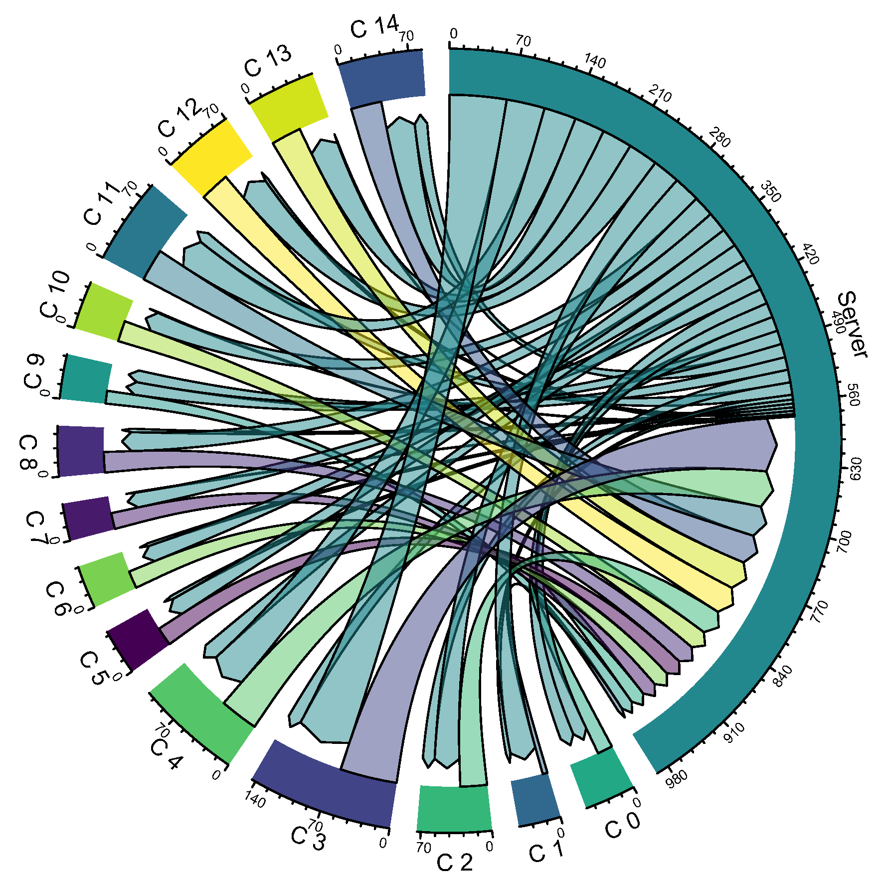
At the same time, we also made a chord graph of the total data throughput of the server and 15 clients in
Figure 14. Through comparison, it can be found that the data throughput on the server side reaches almost half of the total throughput, and the throughput of each client is different. By observing the total amount of data input and output of each end, it can also be found that the input amount of the client is slightly greater than the output, while the output of the server side is slightly larger than the input.
5.3. Scale and Bandwidth
Based on several experiments, we analyze the relationship between the physical object scale of the robot system (equivalent to the client node scale of the distributed virtual simulation network within this framework) and the communication bandwidth in the network.
In the process of data analysis, because the theoretical value of maximum bandwidth is almost impossible due to the existence of synchronization strategy, but assuming that the distribution of bandwidth has specific mean point characteristics, we select the mean bandwidth as the fitted sample point to obtain the distribution relationship of bandwidth with the scale of clients and the total number of attribute values, as shown in
Figure 15.
Among the parameters,
a stands for average size of each property,
b represents the average output of each client,
c is a relative ratio of the volume of properties maintained by the server, and
d could be some necessary command and debug data. As a numeric result, we obtained
KB/s,
KB/s,
KB/s,
d = 2.257655 KB/s. Compared with the form of Equation (
7), we can derive a similar form based on Equation (
10).
Thus, its parameters can be symbolized as
where the
represents property replication traffic related to client scale, and
is the part of the property that is independent of the number of clients.
6. Conclusions and Future Work
In this study, we compared simulation software for multirobot collaboration and identified unique highlights of our work. Our work is to successfully leverage the session mechanism to manage state synchronization and coupling computation across multiple clients. Through the analysis of experimental measurement data, we drew the following important conclusions:
- 1.
We discussed the replication time characteristics and update frequency characteristics when the entities are synchronized. We found that in our system, the replication time of entity synchronization is relatively low, and the update frequency can meet the needs of multirobot collaboration, ensuring the real-time use and accuracy of the system;
- 2.
We analyzed the bandwidth usage of data frames throughout the session. We observed that the server side took up almost half of the data throughput during the entire session, which indicates the rational allocation and utilization of data transfer in our system;
- 3.
We built a bandwidth estimation surface model to estimate the bandwidth requirements of the current model when scaling the server-side scale and synchronization-state scale. This model provides us with an important reference to better plan and optimize the resource allocation and performance of the system.
In future research, we will improve the following key technical details based on this distributed simulation framework:
- 1.
Although the dynamic model update method of coupled objects was given in this architecture, efforts are still needed to further refine the method to support the simulation theory of the system coupling relationship between objects;
- 2.
The synchronous management adopted in this architecture has already partially improved the communication delay problem, but it is still necessary to study the influence of the spatiotemporal consistency problem of the distributed system on multirobot control and decision making;
- 3.
Because the default collaborative network in this study is a simple event-based communication mechanism, it only integrates data services and designs and implements the basic collaboration framework, and it does not consider its impact on the overall distributed network communication bandwidth; therefore, the in-depth study of the collaborative framework will be further promoted in the future in combination with the specific tasks of multirobot system collaborative work.
7. Patents
This section outlines a novel distributed simulation method and system devised specifically for multi-UAV (unmanned aerial vehicle) systems. The methodology bifurcates the distributed simulation tasks inherent in multi-UAV systems into three fundamental concepts: virtual simulation, control perception, and task coordination. These concepts are underpinned by the establishment of three key networks: the distributed virtual simulation network, the perception control subnetwork, and the DDS-based collaborative communication service network.
The distributed virtual simulation network serves as the backbone for deploying virtual simulation tasks across distributed nodes. Its comprehensive server plays a pivotal role by providing a spectrum of essential services, including rule arbitration, map scene management, real-time state synchronization, multipoint session management, intelligent simulation, and real-time situational awareness. Conversely, the client segment within the distributed virtual simulation network furnishes local computing capabilities encompassing dynamics, collision interaction, damage simulation, and graphic rendering.
The system architecture is meticulously crafted to operationalize the aforementioned method, leveraging its inherent advantages such as simplicity, wide applicability, and high integration.
Furthermore, it is pertinent to note the patent details:
Classification: H04L41/042; H04L47/783; H04L9/40; H04L67/08; H04L67/59.
Application Number: 202310416953.5.


