Article

Challenges in Inter-UAV 60 GHz Wireless Communication Utilizing Instantaneous Proximity Opportunities in Flight

1
Social-ICT System Laboratory, Social Innovation Unit, National Institute of Information and Communications Technology (NICT), 4-2-1, Nukui-Kitamachi, Koganei 184-8795, Tokyo, Japan
2
Wireless Systems Laboratory, Wireless Networks Research Center, National Institute of Information and Communications Technology (NICT), 3–4, Hikarino-Oka, Yokosuka 239-0847, Kanagawa, Japan
3
Space-Time Standards Laboratory, Electromagnetic Standards Research Center, National Institute of Information and Communications Technology (NICT), 4-2-1, Nukui-Kitamachi, Koganei 184-8795, Tokyo, Japan
*
Authors to whom correspondence should be addressed.
Drones 2023, 7(9), 583; https://doi.org/10.3390/drones7090583
Submission received: 21 August 2023 / Revised: 9 September 2023 / Accepted: 9 September 2023 / Published: 15 September 2023
(This article belongs to the Special Issue UAVs Communications for 6G)

Abstract

:
Communication using millimeter wave (mmWave) and terahertz bands between unmanned aerial vehicles (UAVs) is a crucial technology for the realization of non-terrestrial networks envisioned for Beyond 5G. While these frequency bands offer remarkably high-speed transmission capabilities of tens of Gbps and above, they possess strong directivity and limited communication range due to the requirement of high-gain antennas to compensate for substantial propagation loss. When a UAV employs radio of such a high-frequency band, the available communication time can be less than one second, and the feasibility of leveraging this ultra-narrow zone, which is only accessible for a short duration in a confined space, has not been investigated. This paper presents the theory behind the ultra-narrow zone in frequencies beyond mmWave and explores the data transfer characteristics at 60 GHz between two UAVs. We demonstrate the transmission of 120 MB of data within approximately 500 milliseconds utilizing the instantaneous proximity opportunity created as the UAVs pass each other. Additionally, we evaluate data transfer while the UAVs maintain a fixed distance, to sustain the 60 GHz link, successfully transmitting over 10 GB of data in the air with a throughput of approximately 5 Gbps.

1. Introduction

Non-terrestrial networks (NTN) are an effective solution for providing wireless communication services to areas that are either uncovered or under-served [1,2,3]. This communication platform facilitates the interconnection of devices across diverse locations encompassing the skies, seas, and even space, employing various vehicles such as satellites, aircraft, and ships. Notably, the utilization of unmanned aerial vehicles (UAVs) as flying wireless base stations enables the establishment of aerial wireless networks, leading to a wealth of pertinent research in this domain [4,5,6,7].
UAVs already play substantial roles across many fields including agriculture, inspection, aerial photography, surveillance, and logistics [8,9]. Through the integration of millimeter wave (mmWave) or terahertz wireless transceivers, UAVs hold the potential of connecting them through exceptionally high-speed wireless channels [10]. This advancement is anticipated to pave the way for the realization of aerial networks with unprecedented data transfer capabilities.
Within the mmWave and terahertz spectrum, the use of highly directional antennas is common practice to counterbalance the substantial propagation loss compared to conventional microwave bands [11,12]. Consequently, communication under these bands is confined to spatially restricted, spot-like communication zones. When transceivers are mounted on vehicles, including UAVs, the positions of these ultra-narrow zones undergo rapid changes, thereby limiting the available temporal and spatial windows for communication. Therefore, it becomes significant to efficiently exploit the opportunities presented by these ultra-narrow spots offering high-speed communication services. Addressing the distinctive attributes of mmWave and terahertz frequencies, extensive research has been dedicated to the development of beam tracking techniques utilizing active phased array antennas [13,14,15]. However, these array antennas encounter challenges as the frequency escalates, exemplified by control complexity and an increase in system cost [16]. In most of these previous studies, air-to-air wireless data transmission between UAVs was limited to theoretical considerations, with few experimental demonstrations.
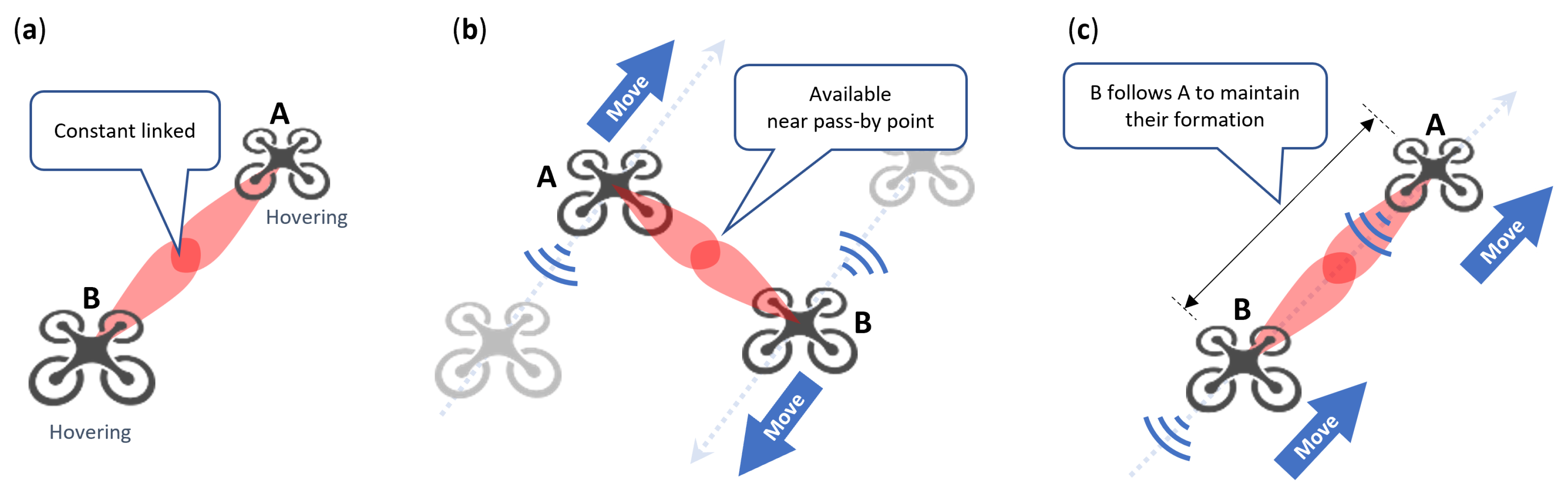
Figure 1 illustrates our concept of a UAV wireless network using proximity opportunities, relying solely on their autonomous navigation ability. Within the context of a drone traffic framework analogous to a drone highway [17], where UAVs densely populate designated airways, UAVs planning routes to various destinations exploit instant proximity opportunities to enable the exchange of high-capacity data. Moreover, UAVs traveling in the same direction engage in continuous data transmission by keeping their proximity. We envision this networking paradigm as the foundation for establishing a wireless data relay network, based on device-to-device (D2D) communications or ad hoc networks, leveraging the dense presence of UAVs within a designated flight zone. The realization of this data relay network, powered by UAVs, requires a comprehensive understanding of the distinct transmission characteristics that emerge with the integration of mmWave or terahertz technologies onto UAV platforms.
This paper explores the viability of utilizing ultra-narrow spot for mmWave or terahertz communications, even without the use of active beam control techniques like beam tracking. The primary contributions of this paper are the following:
  • Clarification of the attributes of ultra-narrow spot and its issue in the context of frequencies beyond mmWave;
  • Presentation of the static data transfer characteristics within the 60 GHz band communication while UAVs are hovering;
  • Examination of the characteristics of short-period communication in ultra-narrow spots at 60 GHz during UAVs’ pass-by and platooning flight.

2. Issue of Ultra-Narrow Spot in mmWave and Terahertz

The mmWave and terahertz bands exhibit spatially limited communication zones in specific directions through the use of directional high-gain antennas (Figure 2a). When these bands are installed on mobile platforms such as UAVs, the resultant zones also move. Thus, they exhibit spot-like characteristics, being both temporally and spatially confined, and thereby enable communication solely within distinct timeframes, periods, and positions. This perspective will be discussed below, incorporating analytical methods.
In general, elevating the frequency of a given wireless system leads to reduced received power. Theoretically, the decrease in received power at higher frequencies stems from two factors: a decrease in the transmitter’s output power and free-space propagation loss. Gustavsson et al. have conducted a survey revealing that output power is empirically inversely proportional to the cube of the carrier frequency f c [18],
P t 1 / f c 3
where P t is the output power from the transmitter. This effect arises due to the complexities of RF implementations involving semiconductors, known as the Johnson limit [19], making the fabrication of high-power transmitters progressively more challenging as the carrier frequency rises.
Considering free-space path loss, we integrate the aforementioned power reduction effect noted in Equation (1) into the well-known Friis transmission equation [20],
P r = G λ 4 π d 2 P t = G c 4 π d 2 P t f c 2 1 f c 5
where P r is the power available at the receiver, G is the total antenna gain, and d is the distance between antennas.
This equation indicates that the received power in a wireless communication system at a given frequency is roughly inversely proportional to the fifth power of that frequency. For instance, elevating the frequency of a 30 GHz mmWave system to 300 GHz terahertz, a tenfold increase, would result in a 50 dB reduction in received power. Note that even stronger attenuation caused by atmospheric gases may occur, potentially exceeding the effect predicted by the theory presented in Equation (2), particularly at frequencies resonating with gas molecules such as oxygen ( O 2 ), nitrogen dioxide ( N 2 ), and water vapor ( H 2 O ) [11].
To counteract this power attenuation and maintain consistent received power, we can employ high-gain antennas which satisfy the following relationship, cancelling out the frequency effect.
G f c 5
Assuming utilization of the generated communication spot through intersection (cross-sectional path within the zone), the cross-sectional spot size, s, as defined in Figure 2a, can be geometrically calculated based on the half power beam width (HPBW) [21],
H P B W = 16 ln 2 ( 180 / π ) 2 10 G / 20 ,
s = 2 d tan H P B W 2 π 180 .
Figure 2b shows the theoretical correlation between frequency and spot size as derived from Equations (3)–(5). As previously mentioned, the received power diminishes at higher frequencies, resulting in a reduced communication range. Consequently, the need arises to augment antenna gain to compensate for this impact, which in turn leads to the narrowing of the spot size. Assuming a distance of 5 m, while the 28 GHz band used in 5G exhibits a spot size of about 3 m, the 60 GHz band targeted in this paper features an approximate one-meter spot size. Even higher frequencies have even more restricted spot sizes, just 16 cm for the 300 GHz band. Despite the constraints imposed by these extremely high frequencies, the available communication spot offers the advantage of enabling data transmission via wider bandwidths at elevated carrier frequencies, facilitating exceedingly high-speed transmissions within the delimited zone.
Furthermore, this communication zone undergoes mobility when mounted on a moving platform, and the timeframe available for utilizing the communication zone is contingent upon the relative velocity. For example, when a communication device traverses a 1 m spot at a velocity of 20 km/h, the available time amounts to approximately 0.18 s. As the crossing speed increases, the duration correspondingly diminishes. Hence, mmWave or terahertz bands deployed on mobile platforms exhibit temporally and spatially restricted ultra-narrow communication zones, introducing novel and unique challenges.
In conventional wireless standards, including the 60 GHz band, an association process that takes charge of the exchange of essential information for data transmission, such as identification, communication parameters, and encryption keys, demands time. This poses challenges in utilizing an ultra-narrow spot beyond the mmWave band. For instance, within a device compliant with IEEE 802.11ad, the wireless LAN standard operating in the 60 GHz band, an average of 2.2 s has been reported as necessary to complete an association process [22], which leads to a difficulty for using ultra-narrow zones that exist for mere fractions of a second. In such scenarios, techniques like beamforming are employed to track the communication zone by scanning beams, with the aim of maximizing the available time for utilizing the communication zone [13]. Nonetheless, executing three-dimensional beam scanning and tracking in UAV communications demands intricate systems, particularly challenging to implement while adhering to stringent constraints on size, weight, and power consumption [23]. This tendency can become more critical as frequency increases, i.e., towards terahertz frequencies [12].

3. Experimental Methods

3.1. System Configuration

Figure 3 shows the appearance of the UAV used in this experimental demonstration. We employed two UAVs (LAB6106FL and UAV-E6106FA2, Eams Robotics Co., Ltd., Fukushima, Japan) with six rotors each. They are integrated with flight controllers (PixHawk2, ProfiCNC Pty Ltd, Victoria, Australia) that enable autonomous navigation through real-time kinematics (RTK) positioning.
Figure 4 provides an overview of the key system configuration. The system has two functions; 60 GHz band data transfer and space–time synchronization. The system controller controls the comprehensive development system through the space–time synchronization unit (STSU), which coordinates time synchronization and 60 GHz band transceiver operations. The STSU was connected to the wireless two-way interferometry (Wi-Wi) modules, which enables space–time synchronization between the UAVs. It also timestamped the output logs from the 60 GHz transceiver, aligning them with the shared time reference between the two UAVs’ systems.
Throughout the experiment, the positions, altitudes, and identifiers of all aircraft were communicated to the ground base station via drone mappers. This allows us to real-time monitor their states to ensure safety and operational integrity [24].

3.1.1. Space–Time Synchronization and Wireless Two-Way Interferometry (Wi-Wi)

Wi-Wi is a wireless device based on the principles of two-way satellite time and frequency transfer (TWSTFT) technology, allowing precise time synchronization via satellites [25]. Operating within the unlicensed 920 MHz band, Wi-Wi engages in bidirectional packet exchange between devices, enabling precise time synchronization with an accuracy measured in tens of nanoseconds by detecting the carrier phase [26]. Moreover, Wi-Wi possesses the capability to measure distance variations at the scale of millimeters [27]. For our study, we used Wi-Wi with the objective of cross-referencing the logs of two distinct remote mmWave wireless communication devices.

3.1.2. RF Configuration for 60 GHz Band Communication

Figure 5 presents the configuration of the 60 GHz band communication segment. Within this system, we employed a communication device compliant with IEEE 802.15.3e standards (Transfer Jet X, Sony Semiconductor Solutions Corp., Kanagawa, Japan), capable of completing an association phase in under 1 millisecond. This feature permits the utilization of ultra-narrow communication zones with a single antenna, obviating the need for beamforming, even within short-duration zones of less than 1 s.
The transceiver output (linearly polarized waves) is transformed into left-handed circular polarization (LHCP) through a circular waveguide mode transition (SWT-15141-SB, Eravant, Torrance, CA, USA) and an mmWave polarizer (SAS-603-14115-F1, Eravant). A conical horn antenna (SAC-2309-141-S2, Eravant) was used to emit the generated LHCP mmWaves into space. It is worth noting that during flight UAVs typically tilt forward, leading to a rotation of the polarization plane (Figure 5c). In the case of linear polarization, this polarization plane rotation results in losses attributed to cross-polarization isolation. To circumvent polarization mismatch stemming from fluctuations in UAV attitude, our experiments used circular polarized waves.
The MAC addresses of the communication devices used in our experiments were treated as known to each other and shared in advance. The specifications regarding with the 60 GHz band communication are listed in Table 1.
The data throughput of the used transceiver is dependent on the received signal strength, as the appropriate modulation scheme is autonomously chosen to balance noise tolerance and data rate considerations. Table 2 shows the designated modulation options in accordance with the IEEE 802.15.3e standard [28]. The throughput and receiver sensitivity are approximate values for single channel operation. Our transceiver chip also supports BPSK modulation for lower-rate transfers, expanding upon the modulation options enumerated in the table.

3.2. Flight Configuration and Routes

The 60 GHz band data transfer was performed across three flight types: hovering, pass-by flight, and platooning flight. Figure 6a–c show both UAVs (A and B) hovering in the air, both UAVs navigating in opposing directions to establish a scenario of their mutual passage, and the follower B maintaining a fixed distance as if following the leader A, respectively.
The pass-by flight configuration entails UAVs navigating towards disparate destinations, leveraging mmWave or terahertz technology as they cross paths. Within this setup, communication is only feasible within a specific range centered around the point of closest approach, albeit constrained to an exceedingly brief temporal window as they move away from the point. Figure 7 illustrates the positional relationship among the UAVs, with a vertical distance of 5 m and a horizontal distance of 5 m as well. Contrastingly, during the platooning flight, the follower B aligns its destination with that of the leader A. This alignment curtails the freedom of flight for the follower B; however, it enables sustained flight in close formation and keeps the ultra-narrow communication link continuously. This configuration is used to create a situation similar to the hovering when UAVs have to fly toward their common destination, thereby enabling stable communication, and is expected to perform the continuous transmission of voluminous data.

4. Experimental Results

In this section, we present the characteristics of data transfer in the 60 GHz band across the three flight configurations including hovering, pass-by, and platooning flight.

4.1. Hovering

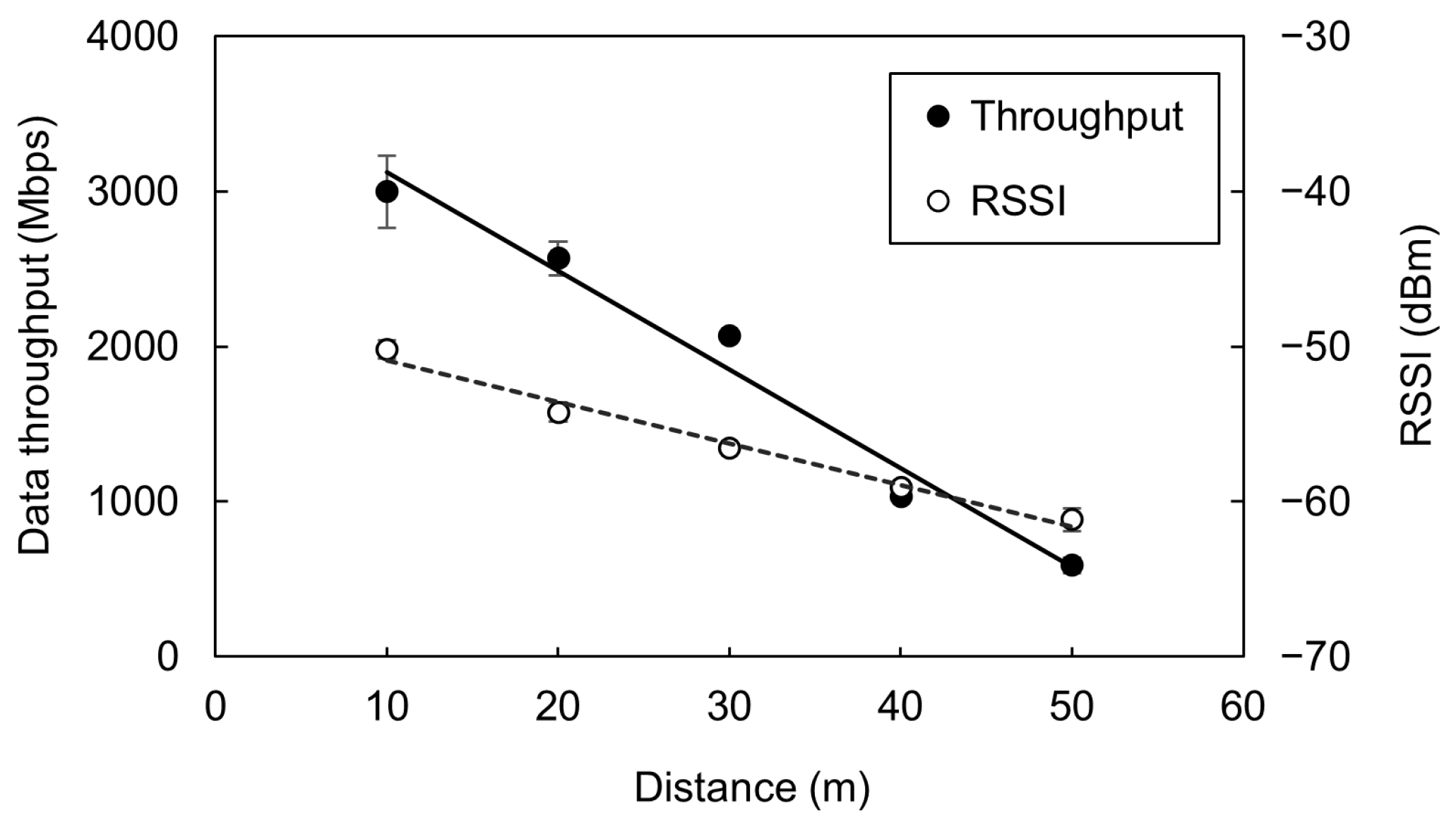
Figure 8 shows the 60 GHz band transfer characteristics during UAV hovering. The distance between the two UAVs was varied from 10 to 50 m in 10 m increments. For each distance setting, data throughput and the received signal strength indicator (RSSI) were evaluated over a one-minute period. The plots are time-averaged over one minute, and the error bars represent the standard deviation of temporal fluctuations. The RSSI diminishes with increasing distance due to free-space path loss, thereby causing a reduction in the throughput attributed to shifts in modulation scheme and coding rate (as described in Section 3.1.2).
While UAVs can sustain a specific position through their inherent flight controllability, practical scenarios involve slight positional perturbations owing to external factors such as wind, turbulence, and errors in on-board sensor output. These perturbations can result in beam misalignment and consequent deterioration in communication quality. The error bars at distances of 10 or 20 m indicate this phenomenon, with the average throughput hovering around 3 Gbps accompanied by fluctuations of 10% or even more during hovering. As the inter-UAV distance decreases and the spot size narrows, fluctuations become more significant. This indicates the need for precise beam alignment to perform high-speed communication over short distances. The identical trend holds for spot size reduction as frequency increases, and it is readily foreseeable that these effects will become even more critical when higher frequencies are employed. Managing consistent communication while hovering becomes challenging under such circumstances.
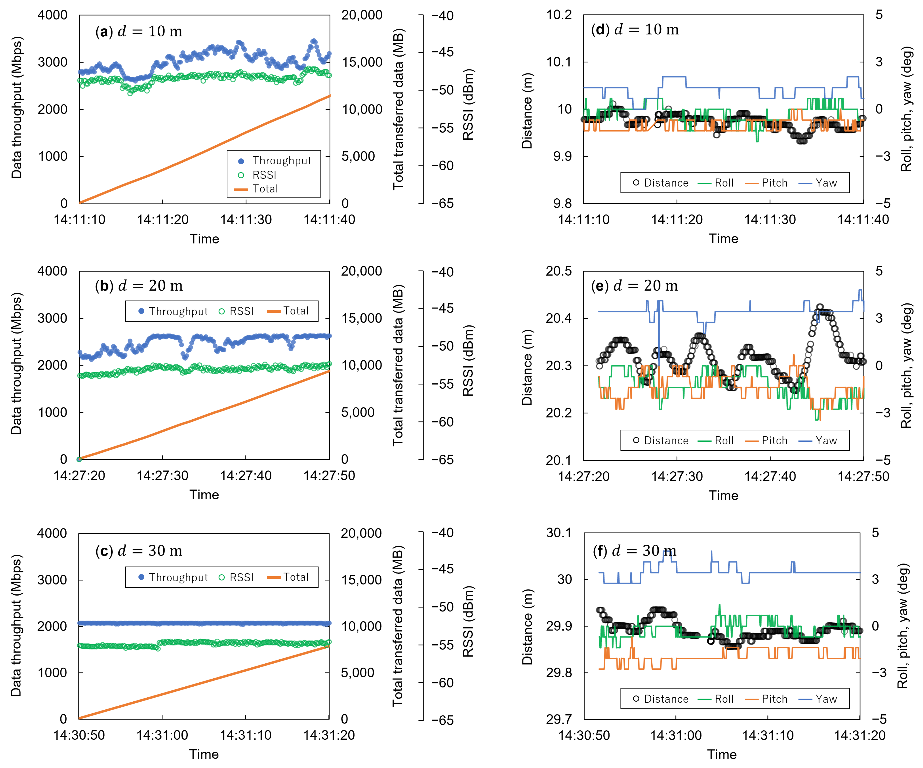
Figure 9 presents the temporal evolution of 60 GHz band data transfer at distances of 10, 20, and 30 m, which are several extracted datasets derived from the source data of Figure 8. At d = 10 m , shown in Figure 9a, although a throughput exceeding 3 Gbps is maintained, fluctuations in the throughput and RSSI are evident. These fluctuations are considered to originate from beam misalignment due to variations in the UAVs’ position and attitude. According to RTK positioning data, the inter-UAV distance changed by approximately 5 cm within a 5 s interval (Figure 9d). This positional variability, coupled with angular jitter of a few degrees, prompts antenna misalignment, making it impossible to consistently sustain the maximal achievable throughput (max. 3.5 Gbps observed). The impacts of such misalignment on mmWaves have been numerically analyzed and reported by Kachroo et al. [29]. Shorter distances increase the average throughput but decrease the spot size, contributing to RSSI and throughput fluctuations due to UAV movement jitter. For distances exceeding 30 m, where a sufficiently large spot size is established, this impact becomes negligible, even in cases of comparable positional or angular misalignment, ensuring sustained and reliable throughput.

4.2. Pass-By Flight

Figure 10 presents the 60 GHz data transfer results during the mutual encounter of UAVs. The RSSI distribution exhibits a mountain-shaped pattern, with weaker RSSI values observed at the edges of the communication zone, reflecting a similar pattern in throughput.
Data transmission between UAVs is confined within a delimited communication window. In the case shown in Figure 10a, where the drones maintained a relative velocity of 5 m/s, the duration of data transmission throughout the passing event was 516 ms, enabling the transfer of a cumulative 126 MB of data. Using a wireless device compliant with IEEE 802.15.3e in our experiments, which establishes the link in less than 1 millisecond, enabled over 99% use of the communication zone for data transfer. If alternative standards, which take a longer time for association processes, had been employed, it would not have completed the association phase within the available timeframe and no actual data would have been transferred. The effective transmission rate remained consistent at 1.86 Gbps for both uplink and downlink across the entire segment, with a peak transmission rate reaching approximately 3 Gbps. Furthermore, the investigation reveals that lower UAV passing speeds lead to prolonged link maintenance intervals and augmented data transmission volumes, as shown in Figure 10b. This indicates that data volume can be adaptively regulated by adjusting flight speeds without the need for flight interruptions or modifications in destination.
In addition to the pass-by flight, which involves both UAVs in motion, data transmission can also be accomplished by employing one stationary UAV as a base station while another UAV passes in proximity. This configuration is demonstrated in Figure 10c,d, and its trends are analogous to the pass-by scenario involving both UAVs in motion. When the relative speeds of the UAVs match, the transmission characteristics exhibit nearly equivalent behaviors in both cases, as observed in the Figure 10c,d, respectively, corresponding to Figure 10a,b. These observations indicate that 60 GHz band data transfer for pass-by flight can be effectively characterized based on the relative speed between the two UAVs.
This approach may also offer a suppression of throughput instability arising from disturbances, as we observed during hovering. While three-dimensional beam tracking is generally required to mitigate this effect, the zone utilization during the pass-by scenario is analogous to beam scanning by getting across the communication zones, hence only two dimensions are required for beam tracking; there is no need for scanning against the axis of travel. In the pass-by flights, the data transfer capacity will be more limited compared to communication during hovering due to the constrained communication time. Nevertheless, when the anticipated data transfer volume by pass-by communication is projected to surpass the desirable content size to send, this method holds the potential to realize high-volume data relay with high-speed transfer between UAVs, while retaining the maneuverability of the drones, as described later.

4.3. Platooning Flight

Figure 11 presents the outcomes of UAVs maintaining a fixed formation distance. By configuring a route that enables both UAVs to navigate at a constant distance, the follower UAV can track the 60 GHz band communication spot created by the leading UAV. Then, their communication link can be sustained, consequently extending the available communication time. We successfully transmitted data exceeding 10 GB within a 30 s platooning flight duration. Since the relative positions of the two UAVs are invariant, they exhibit constant data transmission characteristics similar to hovering. This flight method can perform stable data transmission while the UAVs navigate to the desired coordinates, and has the advantage of enabling both movement of the aircraft and high-volume data exchange.
In situations where hovering is impractical because of the necessity of movement, or when using aircraft types incapable of hovering, pass-by communication offers an effective approach for data transmission without interrupting aircraft mobility. Conversely, when the need arises to transmit larger-volume data, the communication link time can be extended through the platooning flights described here. Thus, employing these distinct methods properly according to the situation is beneficial and efficient.

5. Conclusions

In this paper, we present the results of a demonstration focused on data transfer between UAVs using 60 GHz band wireless communication, with the aim of realizing non-terrestrial networks for Beyond 5G applications. Although mmWave or terahertz frequencies enable ultra high speed communication, their characteristics exhibit a spot-like nature, constraining the spatial and temporal opportunities for communication due to their distinctive directivity and significant propagation losses. This paper delves into the challenges entailed in effectively utilizing the short-duration, high-frequency communication windows unique to these bands.
We analytically quantify the ultra-narrow properties arising from escalating carrier frequencies. In contrast to conventional microwave bands, the spot size is shrunk to a few meters for the 60 GHz band, and to several centimeters at 300 GHz in the terahertz range. These features differ from traditional wireless systems, introducing novel barriers when employing mmWave or terahertz bands in UAVs.
Firstly, we evaluated the data transfer characteristics between two hovering UAVs at varying distances. Shorter distances yielded smaller spot sizes, leading to the throughput being highly sensitive to positional fluctuations and angular misalignment. This causes difficulties in keeping a peak maximal throughput. Spot sizes enlarged as distances increased due to beam spreading, diminishing the impact of throughput fluctuation. When we tried to achieve high-speed communication between close UAVs, the impact of misalignment became significant.
We also investigated the characteristics of data transfer using instantaneous proximity opportunities, assuming scenarios where UAVs were passing each other, or pass-by flight. The data transmission of 126 MB was performed over a 516 ms duration during their passing with a relative speed of roughly 5 m/s. By using wireless communication devices compliant with IEEE 802.15.3e, we were able to use these sub-second limited zone efficiently, resulting in 99% of the total time to data transmission. Other communication standards, which require several seconds for link establishment or association, have difficulties in utilizing such proximity opportunities. The pass-by flight, even when UAVs move in different destinations, exemplifies the potential of leveraging ultra-narrow communication zone to facilitate substantial data exchange between UAVs. Furthermore, for scenarios demanding extensive data exchange, we showed that cooperative route navigation and communication zone tracking can extend the communication timeframe. In one example, by maintaining UAV formation for 30 s, we achieved a consistent transmission of over 15 GB of data. The strategic utilization of these two types of flight methods considering mission requisites emerges as of significance.
These results anticipate that UAVs with different destinations will be able to plan appropriate flight routes to establish over-the-air networks for data exchange and sharing. Even aircraft that do not have hovering capabilities can utilize ultra high frequency communication during passing each other, and this technology is expected to be deployed in high-capacity data relay networks where aircraft collaborate.
We expect the findings of our study to be a promising foundation for aerial wireless networks, wherein UAVs equipped with ultra high frequency devices, can engage in cooperative flight to leverage proximity opportunities. Such technology finds potential applications in various scenarios, such as the rapid collection of high-volume monitoring data in domains such as agriculture, transportation, and infrastructure without the need for landing or hovering, helping to establish high-capacity data distribution networks through drone-based logistics.

Author Contributions

Conceptualization, R.I. and Y.S.; methodology, R.I., K.K. and Y.S.; software, R.I., K.K. and S.Y.; validation, R.I., K.K., L.S., T.M. (Takashi Matsuda), R.M. and Y.S.; formal analysis, R.I.; investigation, R.I., K.K., L.S. and S.Y.; data curation, R.I. and K.K.; writing—original draft preparation, R.I.; writing—review and editing, R.I., K.K., L.S., T.M. (Takashi Matsuda), R.M., S.Y., N.S., T.M (Takeshi Matsumura) and Y.S.; visualization, R.I.; supervision, Y.S.; project administration, Y.S.; funding acquisition, Y.S. All authors have read and agreed to the published version of the manuscript.

Funding

This research received no external funding.

Data Availability Statement

The data are not publicly available due to the privacy of the research. The methods and experimental parameters have been introduced in the manuscript, which can reproduce our results.

Acknowledgments

The authors would like to thank Sony Semiconductor Solutions Corporation, our collaborative research partner, for providing us with the 60 GHz band wireless transceivers.

Conflicts of Interest

The authors declare no conflict of interest.

References

  1. Rinaldi, F.; Maattanen, H.L.; Torsner, J.; Pizzi, S.; Andreev, S.; Iera, A.; Koucheryavy, Y.; Araniti, G. Non-Terrestrial Networks in 5G & Beyond: A Survey. IEEE Access 2020, 8, 165178–165200. [Google Scholar] [CrossRef]
  2. Huang, T.; Yang, W.; Wu, J.; Ma, J.; Zhang, X.; Zhang, D. A Survey on Green 6G Network: Architecture and Technologies. IEEE Access 2019, 7, 175758–175768. [Google Scholar] [CrossRef]
  3. Azari, M.M.; Solanki, S.; Chatzinotas, S.; Kodheli, O.; Sallouha, H.; Colpaert, A.; Mendoza Montoya, J.F.; Pollin, S.; Haqiqatnejad, A.; Mostaani, A.; et al. Evolution of Non-Terrestrial Networks From 5G to 6G: A Survey. IEEE Commun. Surv. Tutor. 2022, 24, 2633–2672. [Google Scholar] [CrossRef]
  4. Baltaci, A.; Dinc, E.; Ozger, M.; Alabbasi, A.; Cavdar, C.; Schupke, D. A Survey of Wireless Networks for Future Aerial Communications (FACOM). IEEE Commun. Surv. Tutor. 2021, 23, 2833–2884. [Google Scholar] [CrossRef]
  5. Sahingoz, O.K. Networking Models in Flying Ad-Hoc Networks (FANETs): Concepts and Challenges. J. Intell. Robot. Syst. 2014, 74, 513–527. [Google Scholar] [CrossRef]
  6. Zeng, Y.; Zhang, R.; Lim, T.J. Wireless Communications with Unmanned Aerial Vehicles: Opportunities and Challenges. IEEE Commun. Mag. 2016, 54, 36–42. [Google Scholar] [CrossRef]
  7. Hayat, S.; Yanmaz, E.; Muzaffar, R. Survey on Unmanned Aerial Vehicle Networks for Civil Applications: A Communications Viewpoint. IEEE Commun. Surv. Tutor. 2016, 18, 2624–2661. [Google Scholar] [CrossRef]
  8. Mohsan, S.A.H.; Othman, N.Q.H.; Li, Y.; Alsharif, M.H.; Khan, M.A. Unmanned Aerial Vehicles (UAVs): Practical Aspects, Applications, Open Challenges, Security Issues, and Future Trends. Intell. Serv. Robot. 2023, 16, 109–137. [Google Scholar] [CrossRef]
  9. Labib, N.S.; Brust, M.R.; Danoy, G.; Bouvry, P. The Rise of Drones in Internet of Things: A Survey on the Evolution, Prospects and Challenges of Unmanned Aerial Vehicles. IEEE Access 2021, 9, 115466–115487. [Google Scholar] [CrossRef]
  10. Zhang, L.; Zhao, H.; Hou, S.; Zhao, Z.; Xu, H.; Wu, X.; Wu, Q.; Zhang, R. A Survey on 5G Millimeter Wave Communications for UAV-Assisted Wireless Networks. IEEE Access 2019, 7, 117460–117504. [Google Scholar] [CrossRef]
  11. Banday, Y.; Mohammad Rather, G.; Begh, G.R. Effect of Atmospheric Absorption on Millimetre Wave Frequencies for 5G Cellular Networks. IET Commun. 2019, 13, 265–270. [Google Scholar] [CrossRef]
  12. Polese, M.; Jornet, J.M.; Melodia, T.; Zorzi, M. Toward End-to-End, Full-Stack 6G Terahertz Networks. IEEE Commun. Mag. 2020, 58, 48–54. [Google Scholar] [CrossRef]
  13. Xiao, Z.; Zhu, L.; Xia, X.G. UAV Communications with Millimeter-Wave Beamforming: Potentials, Scenarios, and Challenges. China Commun. 2020, 17, 147–166. [Google Scholar] [CrossRef]
  14. Wang, W.; Zhang, W. Jittering Effects Analysis and Beam Training Design for UAV Millimeter Wave Communications. IEEE Trans. Wirel. Commun. 2022, 21, 3131–3146. [Google Scholar] [CrossRef]
  15. Ke, Y.; Gao, H.; Xu, W.; Li, L.; Guo, L.; Feng, Z. Position Prediction Based Fast Beam Tracking Scheme for Multi-User UAV-mmWave Communications. In Proceedings of the ICC 2019-2019 IEEE International Conference on Communications (ICC), Shanghai, China, 20–24 May 2019; pp. 1–7. [Google Scholar] [CrossRef]
  16. Xiao, Z.; Zhu, L.; Liu, Y.; Yi, P.; Zhang, R.; Xia, X.G.; Schober, R. A Survey on Millimeter-Wave Beamforming Enabled UAV Communications and Networking. IEEE Commun. Surv. Tutor. 2022, 24, 557–610. [Google Scholar] [CrossRef]
  17. Hamnanaka, M. Optimum Design for Drone Highway Network. In Proceedings of the 2019 International Conference on Unmanned Aircraft Systems (ICUAS), Atlanta, GA, USA, 11–14 June 2019; pp. 923–929. [Google Scholar] [CrossRef]
  18. Gustavsson, U.; Frenger, P.; Fager, C.; Eriksson, T.; Zirath, H.; Dielacher, F.; Studer, C.; Pärssinen, A.; Correia, R.; Matos, J.N.; et al. Implementation Challenges and Opportunities in Beyond-5G and 6G Communication. IEEE J. Microw. 2021, 1, 86–100. [Google Scholar] [CrossRef]
  19. Johnson, E. Physical Limitations on Frequency and Power Parameters of Transistors. In Proceedings of the 1958 IRE International Convention Record, New York, NY, USA, 21–25 March 1965; Volume 13, pp. 27–34. [Google Scholar] [CrossRef]
  20. Friis, H. A Note on a Simple Transmission Formula. Proc. IRE 1946, 34, 254–256. [Google Scholar] [CrossRef]
  21. Mahony, J.D. On the Relationship between the Directivity and the Half-Power Beamwidth in Quasi-Symmetric Pencil-Beam Radiation Patterns. IEEE Antennas Propag. Mag. 2012, 54, 238–243. [Google Scholar] [CrossRef]
  22. LSI Compatible with TransferJet X, a High-Speed Wireless Communication Technology. Available online: https://www.sony-semicon.com/en/products/lsi-ic/transfer-jet.html (accessed on 8 September 2023).
  23. Yang, B.; Liu, M.; Li, Z. Rendezvous on the Fly: Efficient Neighbor Discovery for Autonomous UAVs. IEEE J. Sel. Areas Commun. 2018, 36, 2032–2044. [Google Scholar] [CrossRef]
  24. Shan, L.; Miura, R.; Kagawa, T.; Ono, F.; Li, H.B.; Kato, S.; Kojima, F. Field Tests on ‘drone Mapper’—Location Information and Remote ID Sharing Network in the 920MHz Band for Drones. In Proceedings of the 21st International Symposium on Wireless Personal Multimedia Communications (WPMC2018), Chiang Rai, Thailand, 25–28 November 2018. [Google Scholar]
  25. Shiga, N.; Kido, K.; Yasuda, S.; Panta, B.; Hanado, Y.; Kawamura, S.; Hanado, H.; Takizawa, K.; Inoue, M. Demonstration of Wireless Two-Way Interferometry (Wi-Wi). IEICE Commun. Express 2017, 6, 77–82. [Google Scholar] [CrossRef]
  26. Akasaka, S.; Kameda, S.; Yasuda, S.; Shiga, N. Implementation and Evaluation of Synchronized SS-CDMA Using Wireless Two-Way Interferometry (Wi-Wi). In Proceedings of the 2023 Fourteenth International Conference on Ubiquitous and Future Networks (ICUFN), Paris, France, 4–7 July 2023. [Google Scholar] [CrossRef]
  27. Panta, B.R.; Kido, K.; Yasuda, S.; Hanado, Y.; Kawamura, S.; Hanado, H.; Takizawa, K.; Inoue, M.; Shiga, N. Distance Variation Monitoring with Wireless Two-way Interferometry (Wi-Wi). Sens. Mater. 2019, 31, 2313. [Google Scholar] [CrossRef]
  28. IEEE Std 802.15.3e-2017; IEEE Standard for High Data Rate Wireless Multi-Media Networks, Ammendment1: High-Rate Close Proximity Point-to-Point Communications. IEEE: New York City, NY, USA, 2017.
  29. Kachroo, A.; Thornton, C.A.; Sarker, M.A.R.; Choi, W.; Bai, H.; Song, I.; O’Hara, J.F.; Ekin, S. Emulating UAV Motion by Utilizing Robotic Arm for mmWave Wireless Channel Characterization. IEEE Trans. Antennas Propag. 2021, 69, 6691–6701. [Google Scholar] [CrossRef]
Figure 1. Illustration of mmWave and terahertz communications within a UAV-based network. Two data transfer methods are depicted: instantaneous proximity communications involving UAVs passing each other, and continuous communications wherein UAVs maintain formation. The blue arrows indicate the direction of UAVs’ movement, and the red areas represent the mmWave or terahertz communication links.
Drones 07 00583 g001
Figure 2. Half power (−3 dB) area of mmWave or terahertz. (a) An illustration of a communication spot (red hatched area) and its geometric parameters. (b) Relationship between the cross-sectional spot size and frequency for different distances d.
Drones 07 00583 g002
Figure 3. Photographs of the UAV and onboard equipment utilized in this demonstration.
Drones 07 00583 g003
Figure 4. Configuration of the inter-UAV communication system.
Drones 07 00583 g004
Figure 5. Configuration of the mmWave equipment. (a) Block diagram outlining the principal components related to mmWave emission. The transceiver’s linear polarized output is converted to left-handed circular polarization (LHCP) using the mmWave polarizer. (b) Photograph of the part of mmWave communication components. (c) An illustration of polarization mismatch arising from the UAV’s forward-leaning attitude during flight.
Drones 07 00583 g005
Figure 6. Illustration of the flight types featured in the demonstration. The blue arrow indicates the direction of flight, and the red areas indicate the communication range. (a) Hovering: UAVs remain stationary in flight. (b) Pass-by flight: UAVs navigate in divergent directions to orchestrate a crossing. (c) Platooning flight: Both UAVs uphold a specified distance between them.
Drones 07 00583 g006
Figure 7. Illustration defining the pass-by flight. The blue arrow indicates the direction of flight, and the red areas indicate the communication range.
Drones 07 00583 g007
Figure 8. Data throughput and RSSI of 60 GHz band data transfer with different distances in hovering.
Drones 07 00583 g008
Figure 9. Throughput, amount of transferred data, and RSSI of the experimental inter-UAV 60 GHz data transfer in hovering with (a) the distance d = 10 m , (b) d = 20 m , and (c) d = 30 m . The corresponding distance measured by RTK positioning and relative attitude between the UAVs in hovering are shown in (df), respectively.
Drones 07 00583 g009
Figure 10. Throughput, amount of transferred data and RSSI of the experimental inter-UAV 60 GHz data transfer in pass-by flight on the situation that both of two UAVs were in flight at (a) the relative velocity v r = 5.0 m / s (2.5 m/s and 2.5 m/s), (b) v r = 2.0 m / s (1.0 m/s and 1.0 m/s), and that one was in hovering and the other was in flight at (c) v r = 5.0 m / s , and (d) v r = 2.0 m / s .
Drones 07 00583 g010
Figure 11. Throughput, amount of transferred data, and RSSI of the experimental inter-UAV 60 GHz data transfer in platooning flight for 30 s.
Drones 07 00583 g011
Table 1. Specification of the 60 GHz wireless device integrated into the UAVs.
StandardIEEE802.15.3e
Frequency bandUnlicensed 60 GHz band
Center frequency58.320 GHz
Band width2.16 GHz
Transmission power−5 dBm (approx.)
PolarizationLeft-handed circular polarized 1
AntennaConical horn (23 dBi, HPBW = 11 )
1 The linear polarized wave emitted by the transceiver is transformed into circular polarization with the polarizer.
Table 2. Modulation dependent parameters defined in IEEE 802.15.3e.
ModulationFEC Rate 1Throughput (Gbps)Receiver Sensitivity (dBm)
π /2 QPSK11/152.5813−61
π /2 QPSK14/153.2853−58
16-QAM11/155.1627−55
16-QAM14/156.5707−51
1 Forward error collection (FEC) rate.
Disclaimer/Publisher’s Note: The statements, opinions and data contained in all publications are solely those of the individual author(s) and contributor(s) and not of MDPI and/or the editor(s). MDPI and/or the editor(s) disclaim responsibility for any injury to people or property resulting from any ideas, methods, instructions or products referred to in the content.

