1. Introduction
Micro unmanned aerial vehicles (UAVs) have the characteristics of small size, low cost, and strong flexibility. The quadrotor micro-UAV is one type of them and vertical take-off and landing can be achieved, which further improves the maneuverability of the micro-UAV [
1]. In both the military and civilian fields, the micro-UAV plays an important role, such as military reconnaissance, geographic mapping, aerial videography, fire monitoring, agricultural plant protection, collective rescue, and power inspection [
2,
3,
4]. For the quadrotor micro-UAV, the landing issue is one of the key technologies for improving the autonomous mission execution capability of the UAV. During the landing phase, how to capture the landing position independently without human intervention and determine an autonomous landing strategy is a challenging problem for achieving an accurate fixed-point landing mission of the quadrotor micro-UAV. Hence, intelligent perception and autonomous guidance strategy are necessities.
Generally, it is difficult for a traditional GPS-based guidance strategy to meet the demand of fixed-point landing of the UAV with high precision, since the GPS signals usually show large positioning errors and are prone to be interfered with in constrained environments [
5]. In recent years, with the development of computer vision and image processing technology, vision-based guidance technology has been developed for the autonomous landing of a UAV. More and more attention has been devoted to vision-based guidance owing to many outstanding characteristics, such as independence from the outside world, strong anti-interference ability, high accuracy, and low cost. In the vision-based autonomous landing method of the UAV, usually, two aspects are considered, including the landing marker detection and landing guidance strategy.
With respect to landing marker detection, the edge detection algorithm and deep-learning detection algorithm are widely used. In [
6,
7], the Sobel and Canny edge detection algorithms are used to detect landing markers. Good edge extraction results can be achieved since the landing marker is a cooperative objective that is commonly combined by “H”, “T”, rectangle, circle, triangle, etc. [
8,
9]. However, when the key edge features of the landing marker are lost, traditional edge detection cannot make full use of the rich image information, which will reduce the detection accuracy. To overcome this problem, deep-learning detection methods are used for the landing marker detection, mainly including two categories: two-stage algorithm and one-stage algorithm. The fast region-based convolutional network is representative of a two-stage algorithm where object detection is mainly divided into two parts. A special module is used to generate region proposals, find prospects, and adjust bounding boxes. Regarding the one-stage algorithm, the Single Shot MultiBox Detector (SSD) and You Only Look Once (YOLO) algorithms are usually used, which directly classify and adjust the bounding box based on an anchor. Generally, high detection accuracy can be achieved using a two-stage algorithm but the detection speed might be very slow; while for one-stage algorithms, the detection accuracy is usually lower than that of two-stage methods, the detection speed is higher, which is an advantage for missions that need realtime detection ability. In [
10], a guidance sign detection method named LightDenseYOLO is proposed. Compared with the traditional Hough transform, the speed, and accuracy are effectively improved. In [
11], the YOLO algorithm is modified to improve the recognition and positioning accuracy of the Aruco marker. In [
12], the QR code is used as a landing marker and the convolutional neural network is used to identify the target. In the experiments, the QR code can be identified and the location information is accurately obtained. In [
13], colors are added to the landing marker. A detection algorithm is proposed based on color information. Finally, the landing marker detection is realized based on a large UAV platform.
As mentioned above, several good results have been achieved for vision-based UAV landing in the simulation environment or large UAV platform but there are still challenges in the deep-learning method deployment and real application for the micro-UAV. Considering the payload and computation capability of the micro-UAV, it is needed for getting a balance between the accuracy and speed of the marker detection algorithm.
With respect to the autonomous guidance strategy of the UAV, much research has been studied. In [
14], an adaptive autonomous UAV landing strategy is proposed and the landing experiment is carried out in the Gazebo simulation environment. In [
15], a guidance strategy based on visual and inertial information fusion is proposed for UAV landing on the ship. The relative motion information between the UAV and the landing position is sent to the control system to compute the control commands for guiding the UAV landing. In [
16], a low-complexity position-based visual servoing (PBVS) controller is designed for the vision-based autonomous landing of a quadcopter UAV and the feasibility of the method is proved by numerical simulations and experiments. In [
17], image-based visual servoing (IBVS) technology is used for the autonomous landing of the UAV. In order to improve the accuracy of speed estimation, a Kalman filter is used to fuse GPS data and image data. After simulation and flight experiments, the UAV finally completed tracking and landing on the mobile vehicle with an average error of 0.2 m. In [
18], a fuzzy control method is proposed to control the vertical, longitudinal, lateral, and directional velocities of the UAV. The attitude of the UAV can be estimated based on the vision detection algorithm. In [
19], an autonomous landing method of a micro-UAV based on a monocular camera is proposed. The closed-loop PID controller is used to accomplish the tracking and landing of the UAV. With the increase in sophisticated environments and complex missions for autonomous UAV landings, the issue of the UAV cooperating with moving and tilting targets has received extensive attention. In [
20], an autonomous landing method based on visual navigation is proposed for UAV landing on a mobile autonomous surface vehicle (USV). The landing process is divided into horizontal tracking and vertical landing, and the PID controller is used for the design of the UAV autonomous landing guidance law. In [
21], an autonomous landing method is proposed for the UAV–USV system. The landing marker is recognized first and then the attitude angle of the USV is estimated for the design of the landing strategy. This landing strategy considers the synchronous motion of the UAV and USV and can improve the landing accuracy under wave action. In [
22], an autonomous landing method is proposed for landing the UAV on a moving vehicle where the velocity commands are directly computed in image space. In [
23], a discrete-time nonlinear model predictive controller is designed to optimize the trajectory and time range, so as to land the UAV on a tilted platform. Using the visual servoing method, both PBVS and IBVS must obtain depth information for coordinate transformation. However, for the micro-UAVs, the monocular camera instead of the depth camera is usually used considering the limited size of the UAV. This means that the depth information is difficult to obtain, resulting that the above methods are not suitable for the micro-UAVs. In addition, some guidance strategies are difficult to deploy on the micro-UAV considering the limited computation capability. Usually, different guidance strategies are considered for different application scenarios and different experimental platforms [
24]. In this sense, it is necessary to find an autonomous and easily deployed guidance solution for the autonomous landing of the micro-UAV with consideration given to the limitations of the onboard and computation resource.
In this paper, a vision-based autonomous landing guidance strategy is proposed for a quadrotor micro-UAV based on camera-view angle conversion and a fast landing marker detection approach. The main contribution of the proposed strategy lies on:
- (1)
A vision-based guidance strategy is proposed. This strategy only requires pixel-level coordinates to guide the micro-UAV to land autonomously, without the depth information of the image. The designed autonomous landing strategy shows low complexity and is suitable for the deployment of the micro-UAV;
- (2)
In the landing guidance design, the pixel area obtained from the YOLOv5 detection result instead of the exact depth distance is used to guide the micro-UAV to approach the landing site where the complex estimation of the depth information is avoided;
- (3)
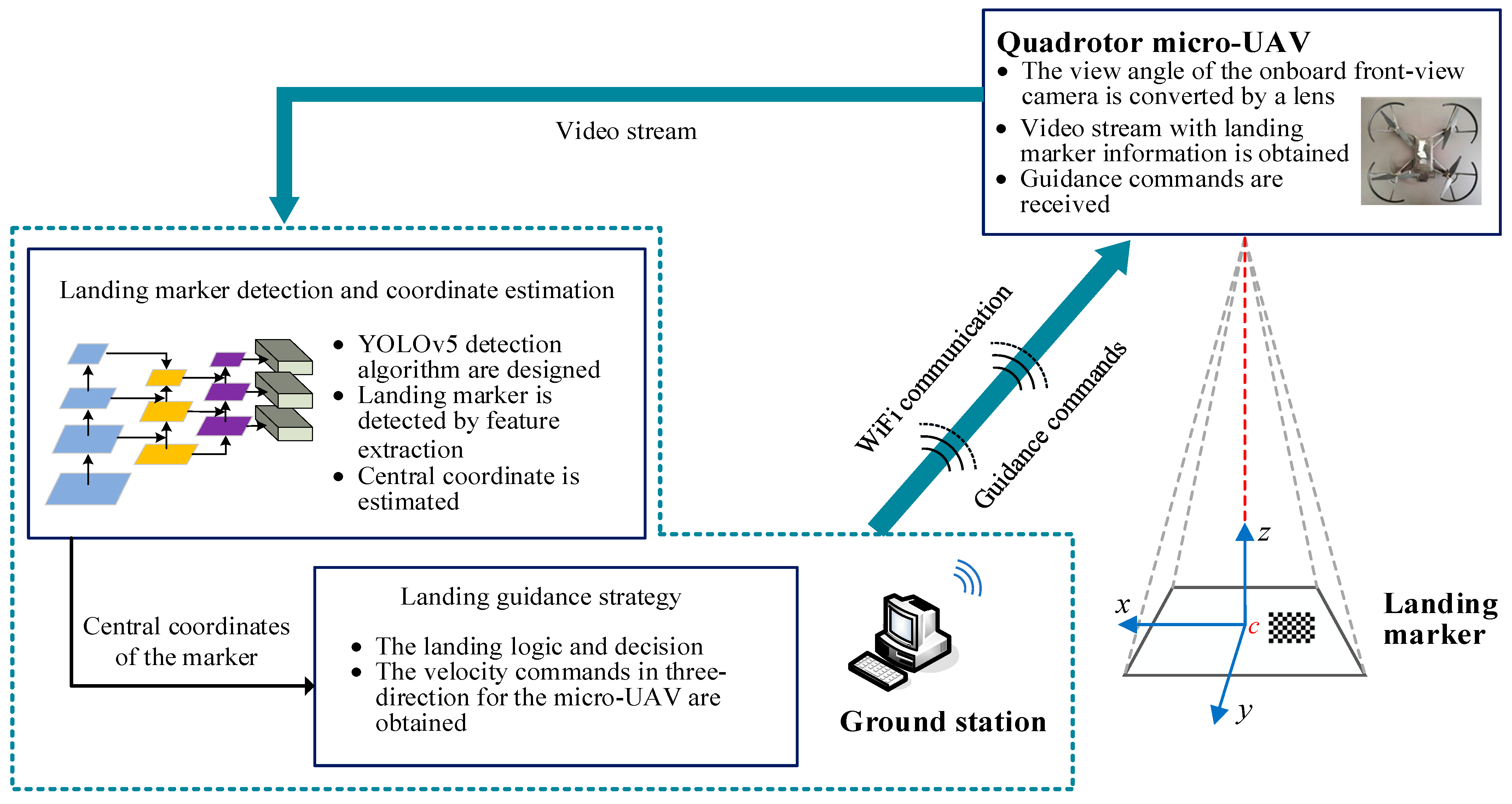
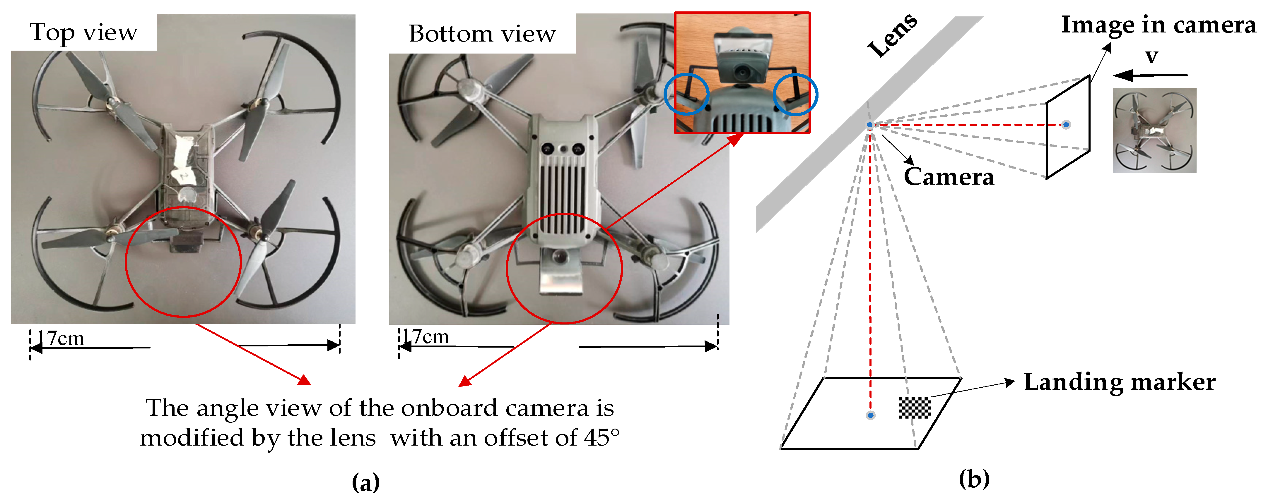
The angle view of the onboard front-view camera is changed through a lens. By this means, the top-down view can be obtained by the onboard camera to capture the landing marker. It provides the possibility of autonomous landing for the micro-UAV with only a front-view camera.
The rest of the paper is organized as follows.
Section 2 introduces the architecture of the autonomous landing guidance system.
Section 3 introduces the landing marker detection and coordinate estimation methods.
Section 4 introduces the modified view angle conversion after refitting DJI Tello UAV and the design of the guidance strategy.
Section 5 analyzes the results of the autonomous landing experiment.
Section 6 presents the conclusions.
4. Autonomous Landing Guidance Strategy
In this section, the guidance strategy of the autonomous landing scheme for the micro-UAV is first designed. Then, the detailed conversion of the view angle for the UAV camera is described. On this basis, the change of the pixel coordinates and pixel area for the landing marker in the visual image when the micro-UAV moves in different directions is analyzed. At last, the landing guidance law is designed to generate the commands including three-directional velocities for completing the micro-UAV landing mission.
4.1. Landing Guidance Strategy
The proposed autonomous landing guidance strategy for the micro-UAV is designed as shown in
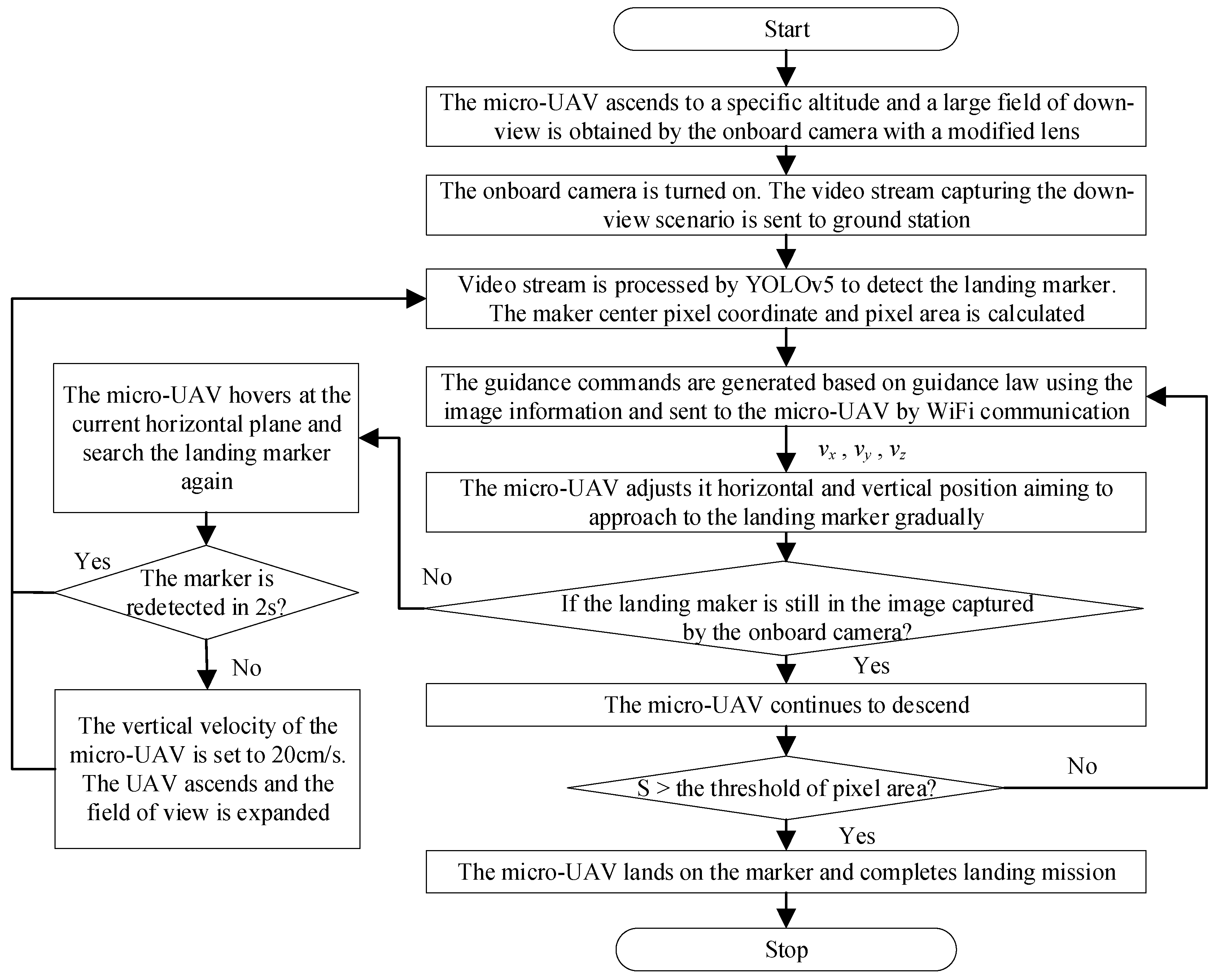
Figure 4. The main steps are described as follows.
Step 1. The view angle of the onboard camera with the front view is converted by a lens so that the downside view can be obtained. The micro-UAV is taken off to an altitude of 6 m to enlarge the field of view of the onboard camera. Before executing the autonomous landing strategy, it is assumed that the micro-UAV has moved into the landing area and that the landing marker is in the view of the micro-UAV’s camera.
Step 2. At the predefined altitude, the onboard camera is turned on. The ground pictures are then captured and the video stream is transmitted back to the ground-station computer by WiFi communication method.
Step 3. On the ground station, the video stream is processed by YOLOv5 in real time aiming to detect the landing marker. Simultaneously, the central-pixel coordinate information of the landing marker is obtained and sent to the guidance strategy.
Step 4. The central-pixel coordinates are provided to the guidance law module. The guidance commands, including three directional velocities, are generated at the ground station. The commands are then sent to the micro-UAV by WiFi communication.
Step 5. According to guidance commands, the micro-UAV adjusts its horizontal and vertical position in order for approaching to the landing marker gradually.
Step 6. During the descent of the micro-UAV, if the marker is lost (that is, the marker cannot be captured by the onboard camera), the micro-UAV hovers without horizontal movement for another 2 s in an attempt to capture the marker again. If the marker still cannot be captured in 2 s, the vertical ascent velocity of the micro-UAV is set to 20 cm/s. The micro-UAV will move up and the field of view of the camera will be expanded. Since the detection area has been expanded, the landing marker can be captured again. Once the landing marker is found again, the micro-UAV will stop ascending and remain in its current position. Then, steps 3–5 are executed.
Step 7. During the descending of the micro-UAV, the pixel area of the landing marker in the image is getting larger and larger. If the pixel area is larger than the preset threshold, the micro-UAV will stop the transmission of the video stream and landing guidance strategy. The micro-UAV then stops and lands on the landing marker.
4.2. Conversion of Camera View Angle
The micro-UAV platform used in this paper is DJI Tello UAV, as shown in
Figure 5a. However, the original onboard camera of the DJI Tello UAV can only capture the front view. In order to achieve the vision-based landing mission, a lens with an offset of 45° is installed, with the help of which the scenario of the downside can be projected into the lens. After the refraction of light, the camera takes images from the lens so the UAV can obtain the down view.
Figure 5a shows the modified lens for the DJI Tello UAV as depicted in the red circle. The changing principle of the view field by the modified lens is shown in
Figure 5b.
In the vision-based landing strategy, the pixel coordinate and pixel area of the landing marker in the image is used to guide the micro-UAV to land autonomously. Therefore, the relationship between the movement of the landing marker in the image and the motion of the micro-UAV must be first clarified. Through this relationship, the flight direction of the micro-UAV can then be determined. Based on several experimental tests, the relationship is obtained as follows. When the micro-UAV moves forward, the pixel position of the landing marker in the image moves upwards instead of downwards in a general sense because of the modified view angle of the lens. When the micro-UAV moves to the left, the pixel position of the landing marker moves right in the image. When the micro-UAV descends, the pixel area of the landing marker in the image captured by the camera will gradually become large as the micro-UAV approaches the landing site. The above relationship is shown in
Table 1.
4.3. Guidance-Law Design
Based on the estimated central coordinates of the landing marker by the algorithm described in
Section 3, the guidance law is designed to generate the landing commands for the micro-UAV. In this paper, the velocity commands in three directions are used to guide the micro-UAV to approach the landing marker. The guidance-law diagram is shown in
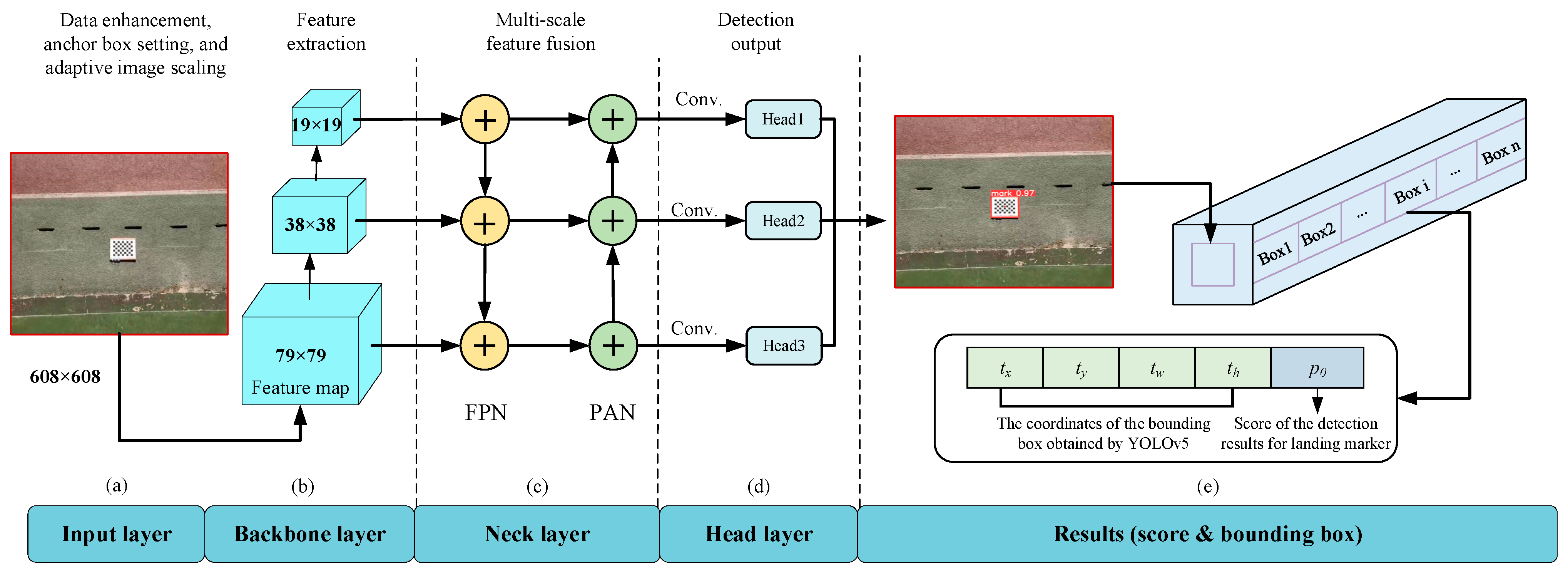
Figure 6. As the micro-UAV descends, the onboard camera continuously captures the images of the landing marker. These images are sent back to the ground station and the landing marker is detected by the YOLOv5 algorithm. Then, the central coordinates
x(
t),
y(
t), and pixel area
S(
t) of the landing marker in the image are calculated and sent to the guidance-law module. After that, compared with the desired pixel coordinates
xd,
yd, and pixel area
Sd, the visual errors are sent to the guidance law to compute the velocity commands
vx,
vy, and
vz in three directions. At last, the commands are sent to the micro-UAV for completing the landing task.
As shown in
Figure 6, the central coordinates
x(
t),
y(
t), and the pixel area
S(
t) of the landing marker at the current moment can be estimated by the real-time YOLOv5 detection algorithm. On this basis, the landing guidance law is then designed including horizontal guidance and vertical guidance, respectively.
Regarding the horizontal guidance, the guidance law is designed as shown in Equations (9) and (10) based on the relationship between the moving direction of the micro-UAV and that of the pixel of the landing marker in the image as depicted in
Table 1.
In this paper, it is assumed that the camera and the UAV can be considered as a whole because of the small size of the micro-UAV and the fact that the camera is fixed on the micro-UAV. Then, the center of the image can be regarded as the horizontal center of the micro-UAV. The goal of the vision-based landing is to adjust the position of the micro-UAV to make sure that the center of the landing marker is exactly on the center of the image, i.e., (xd, yd). Hence, the error between the desired central coordinates (xd, yd) and the current central pixel of the detected landing marker (x(t), y(t)) at a certain time can be used to generate the horizontal-velocity command to guide the horizontal movement of the micro-UAV.
Regarding the vertical guidance, the pixel area
S(
t) is used to design the guidance law as shown in Equation (11).
The flight altitude of the micro-UAV cannot be accurately acquired since the onboard camera of the micro-UAV is a monocular camera without depth information. However, the height-related information is a necessity for the landing guidance. Hence, in this paper, a new method is proposed to estimate the height error between the landing marker and the micro-UAV by the pixel area. The main idea is based on the characteristic that the pixel area of the landing marker in the image captured by the camera will gradually become larger as the micro-UAV approaches the landing marker. Then, the pixel area S(t) of the landing marker can be used as an indirect indicator to represent the height of the micro-UAV relative to the landing marker. In the proposed guidance strategy, at the end of the landing guidance, the pixel area of the landing marker can be set as Sd which is a threshold used as a reference indicator for stopping the video transmission and the landing guidance strategy. That is, if the pixel area of the landing marker is greater than the threshold at a certain time, the micro-UAV lands on the marker and completes the landing mission. The error between the desired pixel area and the current pixel area of the detected landing marker is calculated by Equation (11), which can also be regarded as a parameter to adjust the altitude of the micro-UAV to approach the landing marker.
After calculating the visual errors in the three directions (
ex(
t),
ey(
t), and
ez(
t)), a PID guidance law is designed to generate the velocity commands in three directions. By the guidance law, the micro-UAV gradually decreases the visual errors and achieves the landing task. The autonomous guidance law of the micro-UAV can be seen in two parts: the horizontal and the vertical landing. In the horizontal direction, the visual errors
ex(
t) and
ey(
t) are sent to the PID guidance law to generate the velocity in the
x, y direction, as shown in Equations (12) and (13). The visual error
ez(
t) is sent to the PID guidance law to generate the velocity in the
z direction, as shown in Equation (14).
where
vx(
t),
vy(
t), and
vz(
t) represent the velocity in the
x, y, and
z direction, and
ex(
t),
ey(
t), and
ez(
t) are the visual errors in the
x, y, and
z directions.
Kpx,
Kpy,
Kpz,
Kix,
Kiy,
Kiz,
Kdx,
Kdy, and
Kdz are the gains of PID guidance law.
The above guidance law is used to calculate the velocity commands in three directions at the ground station, and the commands are then sent to the micro-UAV to reduce the position error relative to the landing marker. By this means, the micro-UAV gradually descends and lands on the landing marker finally.
5. Experiment Results Analysis
To verify the proposed method, four experiments are conducted including the landing marker detection, the indoor experiment of the autonomous landing of the micro-UAV, the outdoor experiment of the autonomous landing of the UAV, and the experiment of the micro-UAV landing on the moving target. The first experiment is used to evaluate the detection performance of the landing marker for the following autonomous UAV landing mission. The second experiment is to guide the micro-UAV to land on a marker in an indoor laboratory where a motion capture system can be used to monitor the trajectory of the UAV landing process. The third experiment is an outdoor experiment to realize the autonomous landing task of the micro-UAV in the real world. The fourth experiment is performed to verify that the micro-UAV can land on the moving target using the UAV autonomous landing strategy proposed in this paper. In this section, the experimental platform is first introduced, and the experimental process is then presented in detail. Meanwhile, the experimental results are analyzed. Finally, our experimental results are compared with other vision-based methods of autonomous UAV landing.
5.1. The Experimental Platform
In the experiment, the quadrotor micro-UAV platform is DJI Tello UAV. The micro-UAV is equipped with four motors, one battery, a WiFi module, a camera, etc. The camera of the UAV can provide 1280 × 720 pixels video resolution. Detailed parameters are shown in
Table 2. The computer used in the ground station is equipped with an i5-7300HQ CPU and NVIDIA RTX3050 GPU. The computers used for the motion capture system in the indoor laboratory are equipped with an i7-11700F CPU.
The size of the landing marker is set to be 225 mm × 175 mm. The maximum altitude of the landing marker to be detected by the vision system is 6 m when using a 225 × 175 mm size landing marker. If the landing marker needs to be detected at a higher altitude, a larger size landing marker is needed. The larger landing marker allows for the start of the landing mission from a higher altitude. When the flight altitude is 6 m in the outdoor experiment, the range of the view field can be captured by the micro-UAV is 8.50 m × 6.50 m. When the flight altitude is 2 m in the indoor experiment, the range of the view field can be captured by the micro-UAV is 2.90 m × 2.20 m.
5.2. The Landing Marker Detection
In this paper, the landing marker detection method is the YOLOv5 algorithm. To evaluate the performance in terms of detection accuracy and speed of the YOLOv5 detection method, two other network-based detection methods are also conducted as a comparison. With respect to the evaluation indicator, detection accuracy is one of the most important indexes for object detection algorithms, since the landing marker should be recognized at first, which is a basis for the following autonomous landing mission. The higher the accuracy of detection means that the detection algorithm is more effective in detecting the landing marker. At the same time, the detection speed is a critical factor for the real-time micro-UAV application. It is generally considered in vision-based flight applications that the real-time requirement can be met when the processing algorithm can complete the detection process of the current frame before the next frame is sent to the ground-station computer. Therefore, the detection speed should be greater than the sampling rate (FPS = 30 in this paper) of the camera. Hence, FPS ≥ 30 is the minimum standard to ensure that the micro-UAV can process the image timely during the autonomous landing mission. The commonly used single-stage object detection algorithms including SSD and YOLO are chosen for comparison. In network training and testing, the same landing marker datasets made by ourselves are used, and the equipment used is also completely consistent with each other. The average precision, as depicted in Equation (7), is used to indicate the accuracy of the algorithm, and FPS in Equation (8) is used to express the speed of the algorithm. The test results are shown in
Table 3.
As shown in
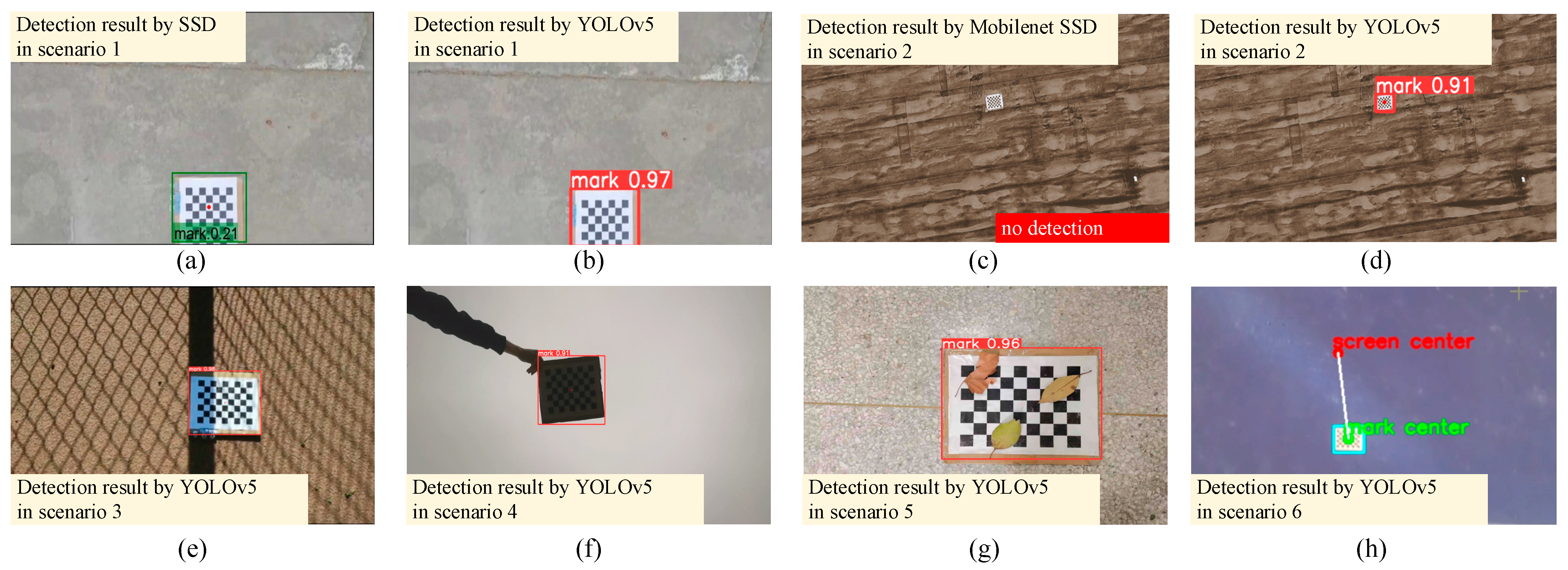
Table 3, the SSD algorithm has the highest accuracy achieving 99.7%. However, the detection speed does not meet the requirement of real-time applications. The Mobilenet SSD where the original VGG network is replaced by the MobilenetV2 network, can effectively improve the detection speed of the SSD algorithm, but the accuracy is obviously reduced and it is unable to identify small targets at a high altitude, as shown in
Figure 7c. The YOLOv4 algorithm has a detection accuracy of 99.1% and an average detection speed of 30 FPS. The YOLOv4-tiny algorithm has a detection accuracy of 98.9% and an average detection speed of 34 FPS. The YOLOv5 algorithm has a detection accuracy of 99.5% and a detection speed of 40 FPS. The accuracy and speed of detection are better than the YOLOv4-tiny algorithm and the YOLOv4 algorithm. In addition, it can accurately recognize a landing marker in a variety of complex scenarios. It can be concluded that the YOLOv5 algorithm can achieve good detection results while meeting the real-time requirements at the same time.
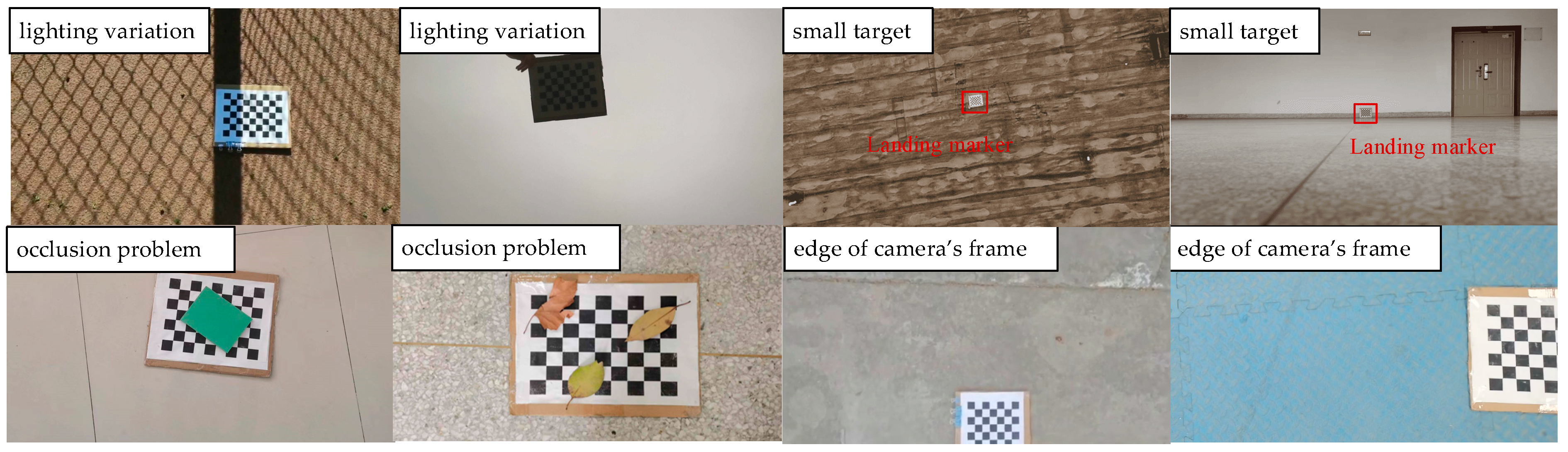
Figure 7 shows the detection results of several landing marker images in different scenarios using different methods. In
Figure 7a, the SSD algorithm is poorly detected at the edge of the camera’s frame. In
Figure 7b, compared with the detection result of the SSD algorithm in
Figure 7a when the target is at the edge of the camera’s frame, the YOLOv5 algorithm can still accurately detect the landing marker in this scenario and the score is greater than SSD. In
Figure 7c, the result of the Mobilenet SSD algorithm is present when the landing marker is small in the image due to the high altitude of the micro-UAV. It can be seen from the detection result that the algorithm cannot detect small targets correctly. In
Figure 7d, the YOLOv5 algorithm can accurately detect the landing marker even if the landing marker is small in the image, compared with the detection result of the Mobilenet SSD algorithm in
Figure 7c.
Figure 7e–f show the detection results of the YOLOv5 algorithm in different scenarios, including a strong light environment and a cloudy environment. The results show that the YOLOv5 algorithm can adapt to changes in light intensity. In
Figure 7g, a large area occlusion environment is considered and the result shows that even if the marker is blocked by an object, the marker detection can still be accomplished by the YOLOv5 algorithm using the internal image features. In
Figure 7h, the YOLOv5 algorithm is deployed on the DJI Tello UAV for real-time detection. The result shows that the algorithm can be deployed on the UAV to achieve high detection accuracy and speed. Based on the above analysis, the landing marker in various scenarios can be accurately detected by the YOLOv5 algorithm, which indicates that it is suitable for the research of vision-based autonomous landing of the micro-UAV.
5.3. The Indoor Experiment of the Autonomous Landing of the Micro-UAV
Before a real flight test, the WiFi communication between the micro-UAV and the ground station is first established. The landing marker is placed in an open area. When the micro-UAV enters the autonomous landing area, the ground information can be captured using the onboard camera with a modified lens. Then, the video stream is sent to the ground-station computer. On the ground-station computer, the deep-learning YOLOv5 algorithm is pretrained to detect the returned video images in real time. Once the landing marker is recognized, its central-pixel coordinate is estimated and then used for guidance commands generation. The central coordinate is sent to the PID guidance law to compute the UAV guidance commands, which are finally sent to the micro-UAV to perform the autonomous landing task. At the same time, the motion capture system installed around the wall of the laboratory is used to monitor the micro-UAV. Hence, the flight data of the micro-UAV during the indoor experiment process can be saved for further analysis.
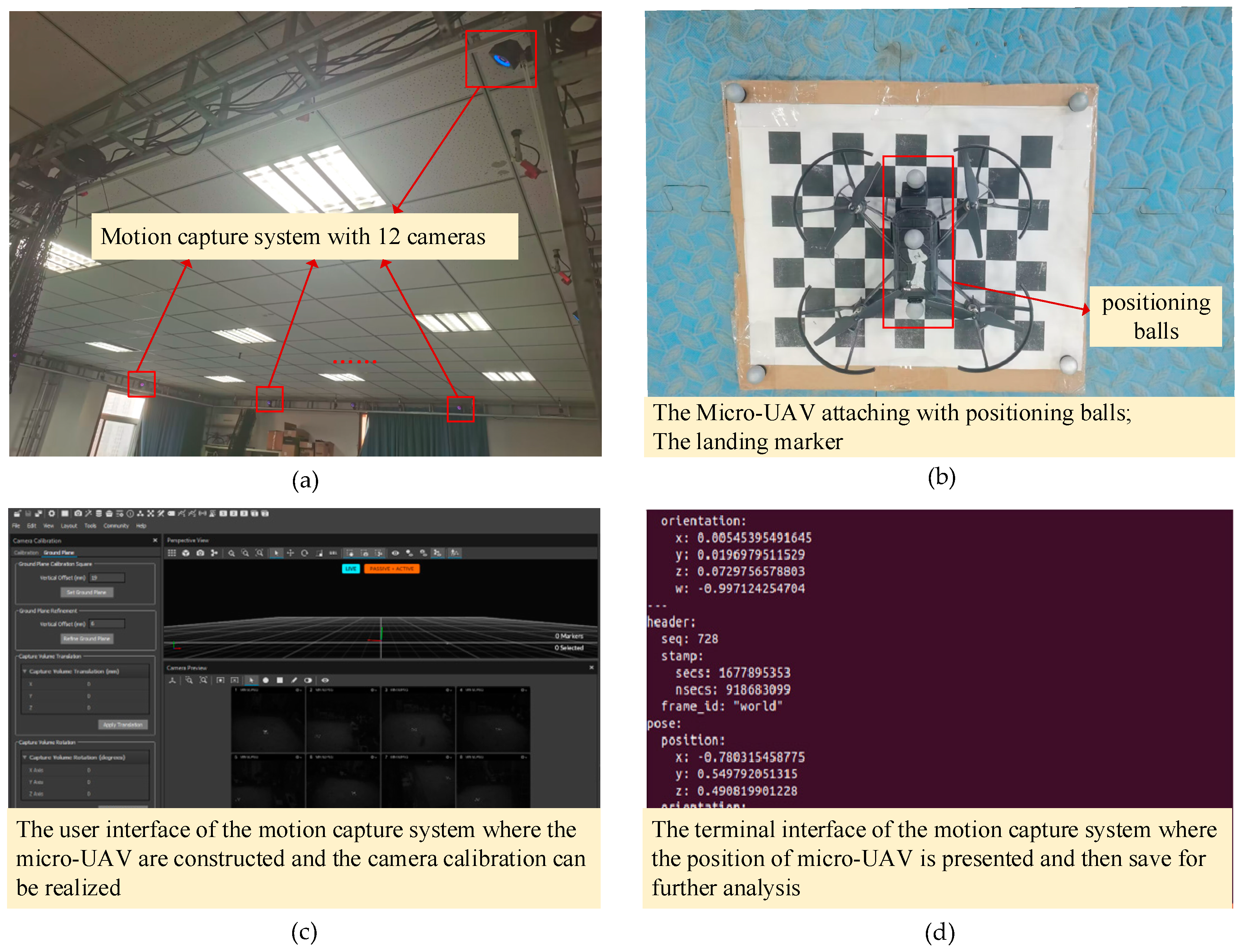
Figure 8 shows the hardware and software used in the indoor experiment.
Figure 8a is a physical image of the motion capture system, consisting of 12 high-definition cameras.
Figure 8b shows the micro-UAV and landing marker used in the experiment. Three positioning balls are fixed on the micro-UAV and used to compute the position of the micro-UAV by the motion capture system.
Figure 8c shows the user interface of the motion capture positioning system, which is responsible for camera calibration, rigid bodies creation, and micro-UAV monitoring.
Figure 8d shows the terminal interface of the motion capture system where the position of the micro-UAV is presented and then save for further analysis.
In the indoor experiment, the desired altitude of the micro-UAV is set to be 1.8 m, the adjustment range of the horizontal velocity is set as [−8 cm/s, +8 cm/s], and the maximum descent velocity is set to be 8 cm/s. The gain of the PID guidance law for the experiment is set as shown in
Table 4, and the landing guidance strategy updates the commands with a sampling and updating frequency of 10 Hz.
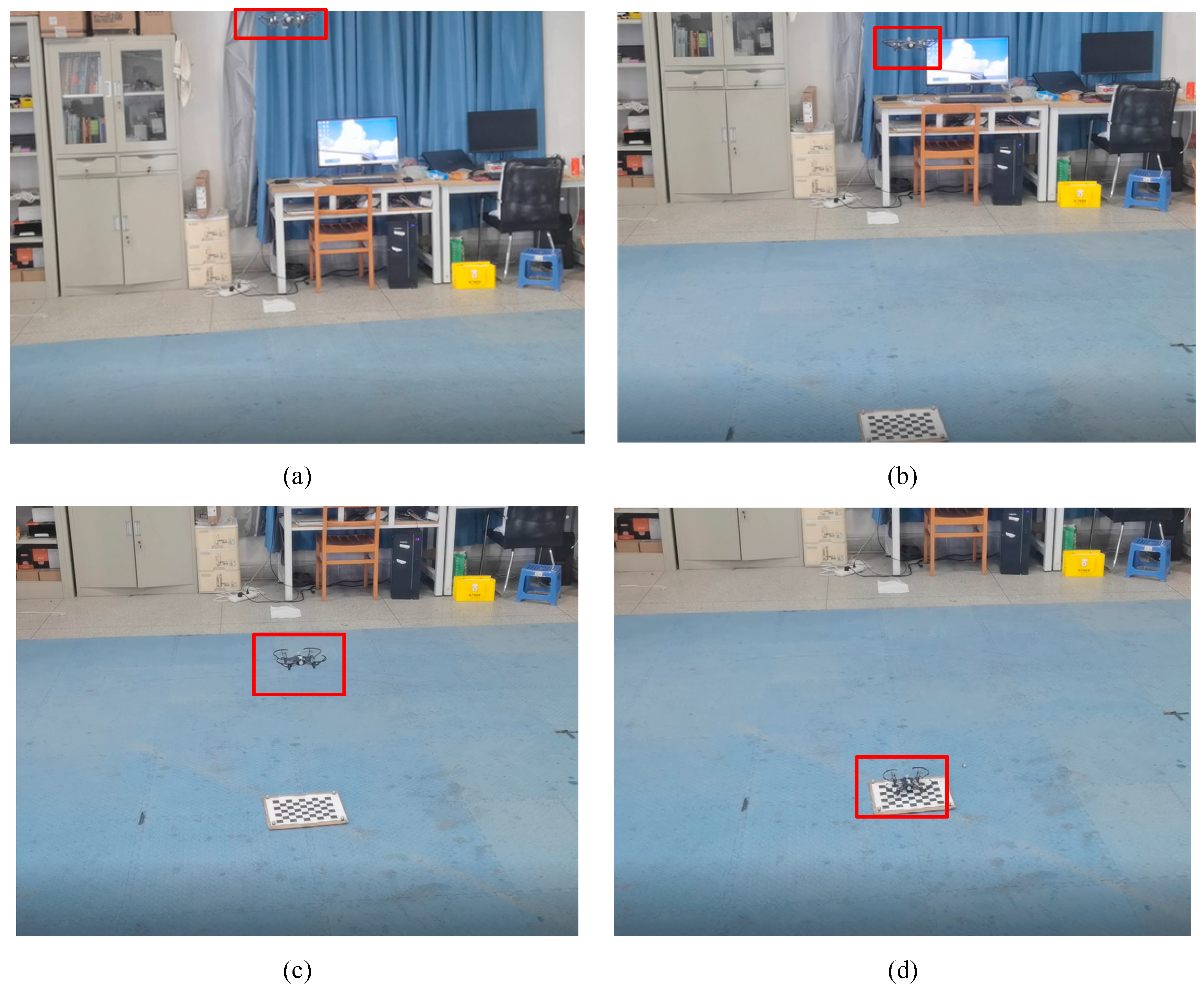
Figure 9 shows the indoor experiment results of the autonomous landing of the micro-UAV, including four representative stages. In
Figure 9a, the micro-UAV ascends to the desired altitude of 1.8 m and starts capturing images of the ground. In
Figure 9b, the micro-UAV autonomously descends according to the commands generated by the guidance strategy. In
Figure 9c, the pixel area of the landing marker exceeds the threshold; hence the micro-UAV hovers at an altitude of 0.6 m and stops the video transmission and autonomous guidance strategy. In
Figure 9d, the micro-UAV finally lands on the marker completing the landing task. In addition, the motion capture positioning system is used to collect the flight trajectory of the micro-UAV during the indoor experiment. The position curves in the
x,
y, and
z directions and the three-dimensional flight trajectory and for the autonomous landing of the micro-UAV are shown in
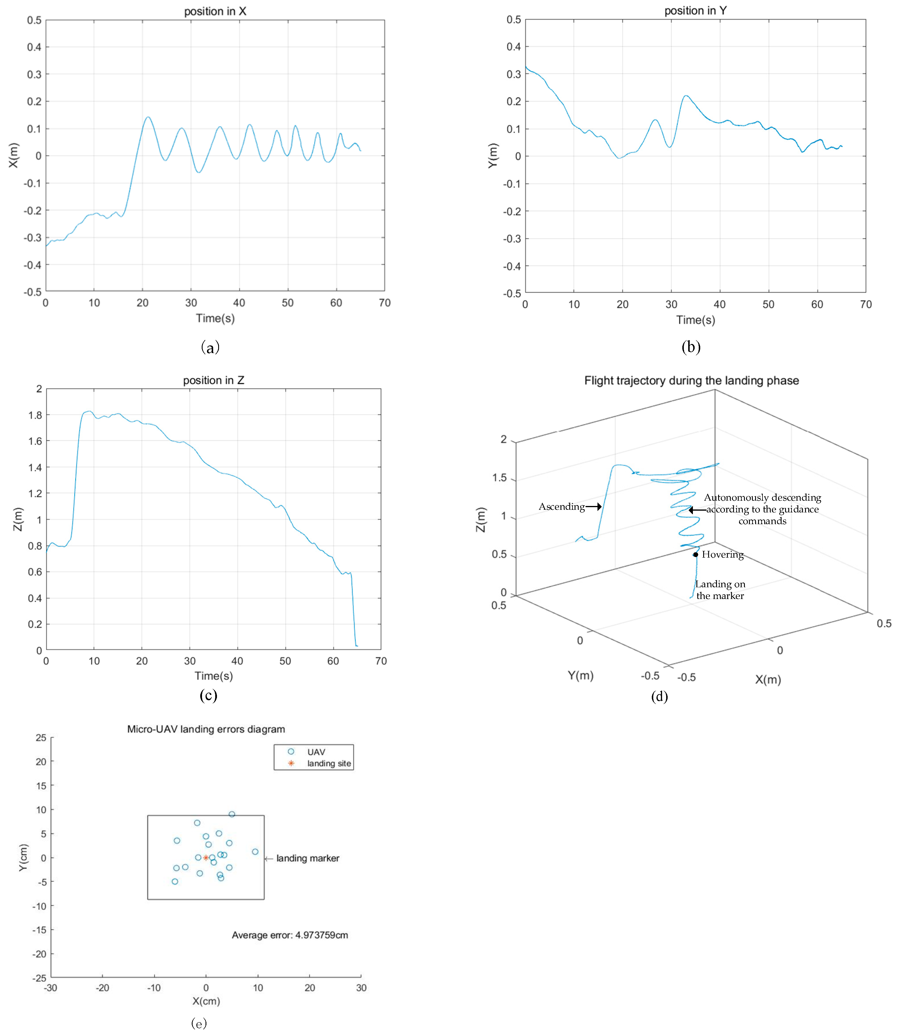
Figure 10.
Figure 10a shows the position of the micro-UAV in the
x direction. The micro-UAV reaches the landing marker at around 20 s and then adjusts within a range of [−0.1 m, 0.1 m].
Figure 10b shows the position of the micro-UAV in the
y direction. The micro-UAV adjusts its position and finally reaches the landing marker.
Figure 10c shows the position of the micro-UAV in the
z direction. Due to height limitations in the laboratory, the maximum altitude is set to be 1.8 m. At around 8 s, the micro-UAV ascends to the desired altitude and then autonomously descends according to guidance commands in order to approach the landing marker. At around 61 s, the micro-UAV descends to 0.6 m. Based on the predesigned guidance strategy, if the pixel area of the landing marker exceeds the threshold, the micro-UAV will stop the autonomous landing guidance. Hence, the micro-UAV hovers for a few seconds at the altitude of 0.6 m and then lands on the landing marker. The whole autonomous landing time of the micro-UAV takes 50 s.
Figure 10d shows the 3D flight trajectory of the micro-UAV during the indoor autonomous landing experiment.
Figure 10e shows the distribution diagram of the UAV landing positions and the target-site position in the static target landing experiments. The UAV took off from different directions to conduct 20 landing experiments and all the landings were completed. It can be seen from the diagram that the average error between the UAV landing position and the target position is 5 cm.
5.4. The Outdoor Experiment of the Autonomous Landing of the Micro-UAV
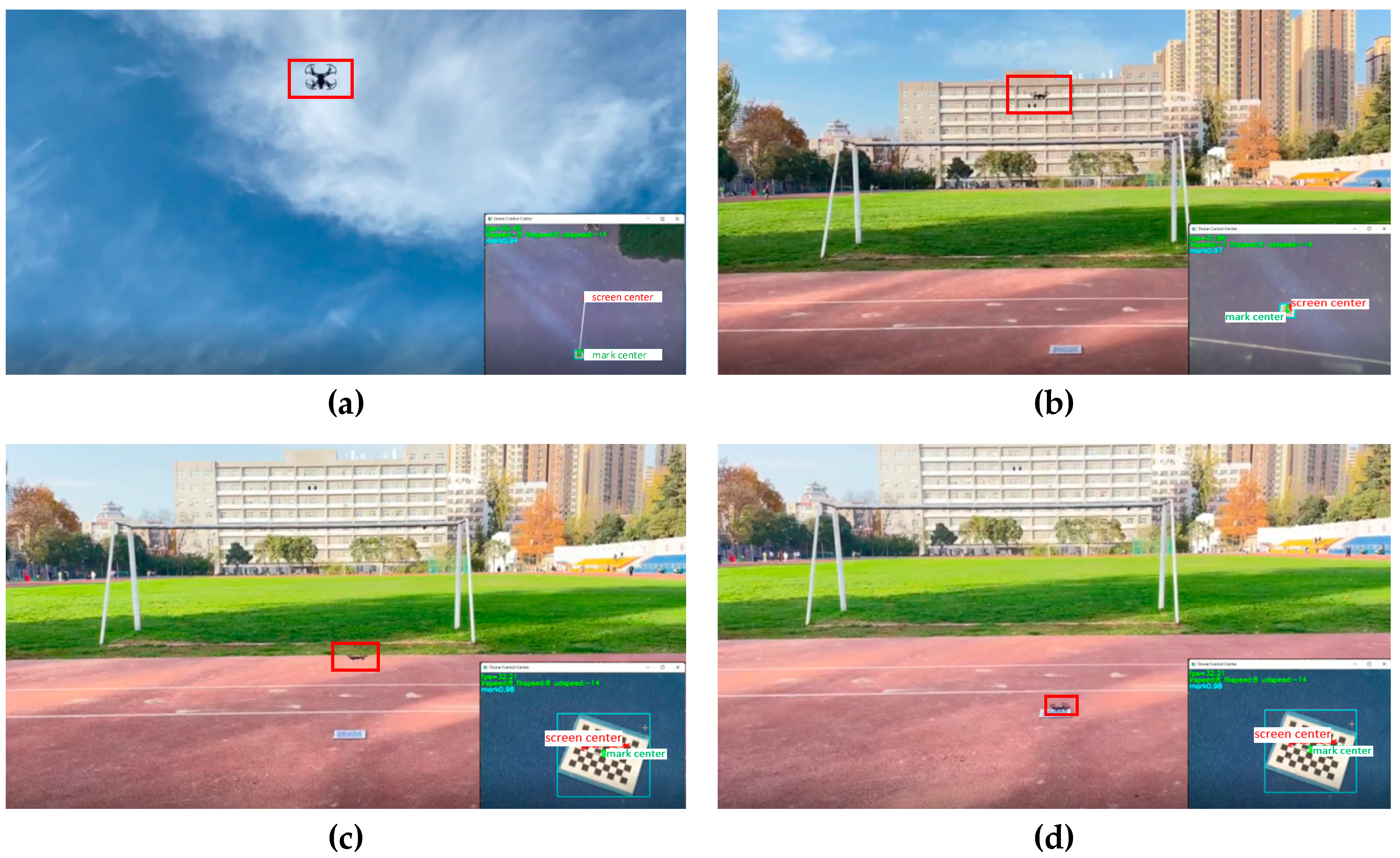
The autonomous landing experiment is carried out in the outdoor environment. The main configuration of the guidance experiment is the same as the indoor experiment except that no motion capture system is used. In the outdoor experiment, the desired altitude of the micro-UAV is set to be 6 m, the horizontal velocity adjustment range is set to be [−8 cm/s, +8 cm/s], and the maximum descent velocity is set to be 16 cm/s. The flight images are recorded by a mobile phone, and the detection images are recorded by the ground station. As shown in
Figure 11, the large image shows the flight scene of the micro-UAV and the small image at the bottom right corner shows the real-time detection results by the YOLOv5 algorithm. The relative position of the micro-UAV and landing marker can be seen in the detected images. The red point is the position of the micro-UAV and the green point is the position of the landing marker. The velocity of the micro-UAV in three directions, the score for the landing marker detection, and the FPS are also shown in these images.
Figure 11 shows the four main stages of the autonomous landing flight experiment.
Figure 11a shows the first stage, where the micro-UAV ascends to 6 m in order to enlarge the field of view of the onboard camera. The camera is then turned on to capture ground images and the video is transmitted back to the ground station. In
Figure 11b, the central coordinates and pixel area of the landing marker are obtained by the YOLOv5 algorithm and then sent to the guidance law to calculate the velocity commands in three directions. The micro-UAV receives the commands and autonomously adjusts its position to approach to the landing marker. In
Figure 11c, the pixel area of the landing marker in the image is larger than the set threshold; then, the micro-UAV stops the video transmission and autonomous landing guidance strategy. In
Figure 11d, after receiving the end instructions, the micro-UAV turns off the rotors to complete the final landing. The autonomous landing of the micro-UAV takes about 80 s. Overall, the proposed guidance strategy can complete the outdoor autonomous landing mission as analyzed in the experiment results.
5.5. The Experiment of the Micro-UAV Landing on the Moving Target
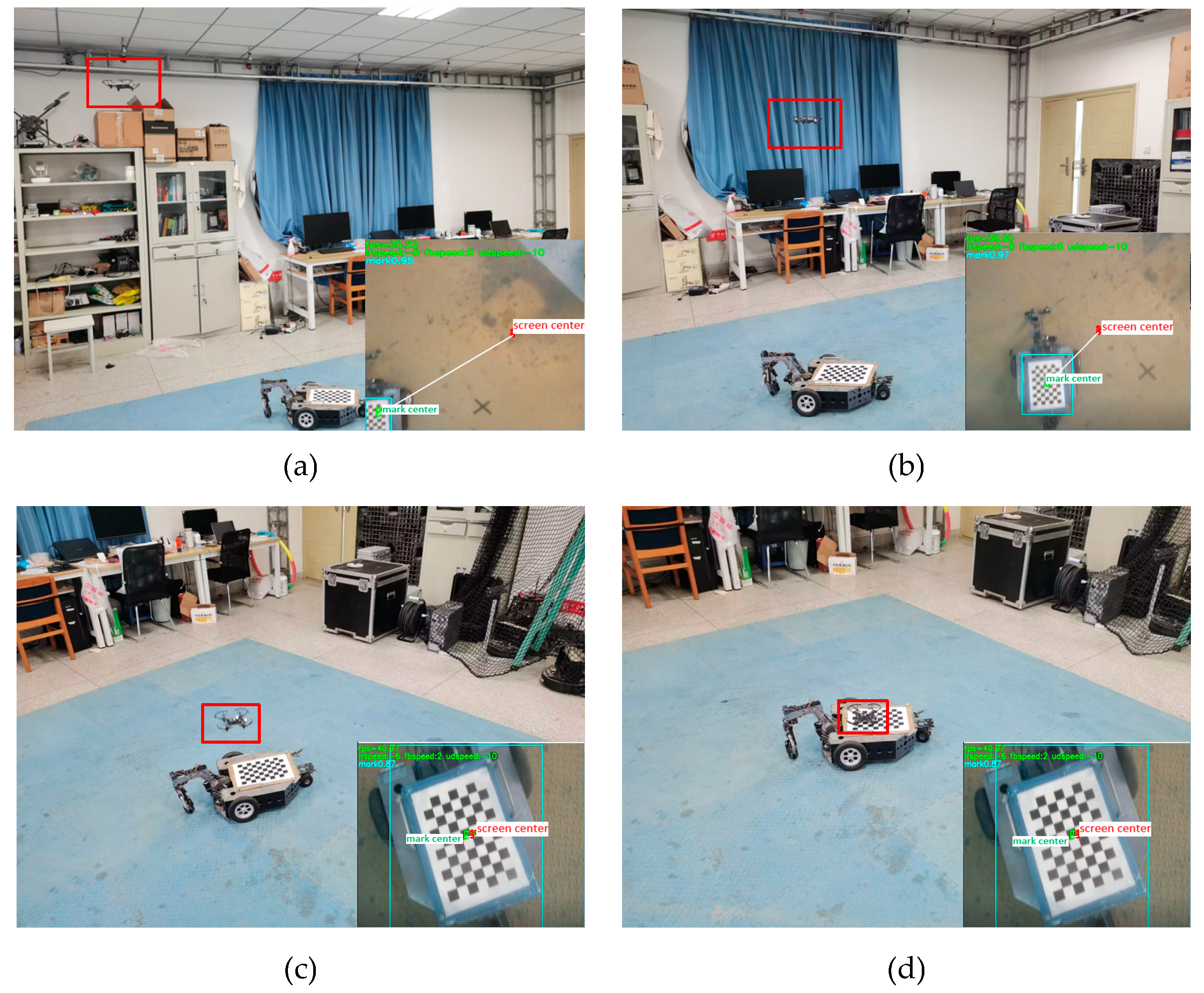
In order to verify the suitability of the proposed autonomous landing strategy for mobile scenarios, an experiment of micro-UAV landing on a moving platform is performed in the paper. In the experiment, the vehicle moves forward with the landing marker and the micro-UAV tracks the mobile vehicle and lands on the landing marker. The starting altitude of the micro-UAV is set to be 2 m, the adjustment range of the horizontal velocity is set as [−8 cm/s, +8 cm/s], and the maximum descent velocity is set to be 10 cm/s.
Figure 12 shows the four images of the autonomous landing experiment that the micro-UAV lands on the mobile vehicle.
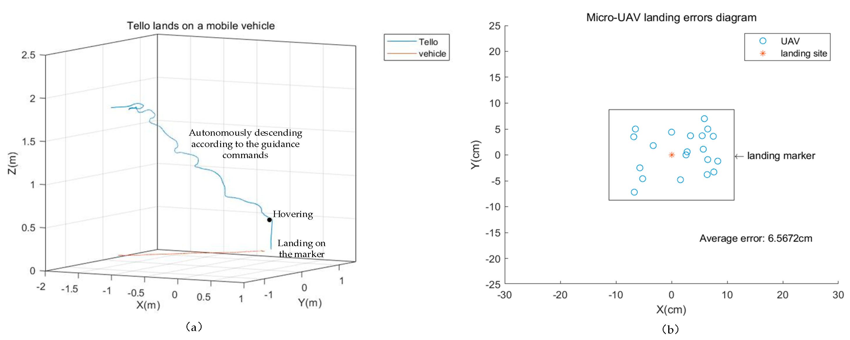
Figure 13a shows the three-dimensional trajectory diagram of the micro-UAV for landing on the mobile vehicle. The whole autonomous landing time of the micro-UAV takes 40 s.
Figure 13b shows the micro-UAV landing positions and the target-site position. The micro-UAV took off from different directions to conduct 20 landing experiments and all the landing missions were completed. It can be seen from
Figure 13b that the average error between the UAV landing position and the target position is 6.6 cm.
In order to compare the performance of the proposed autonomous landing strategy with existing vision-based autonomous landing methods for the UAV. The obtained results are summarized in
Table 5 and the main differences between them are analyzed.

 ,
, 


