

Exploring Radar Micro-Doppler Signatures for Recognition of Drone Types


Abstract
:1. Introduction
2. Materials and Methods
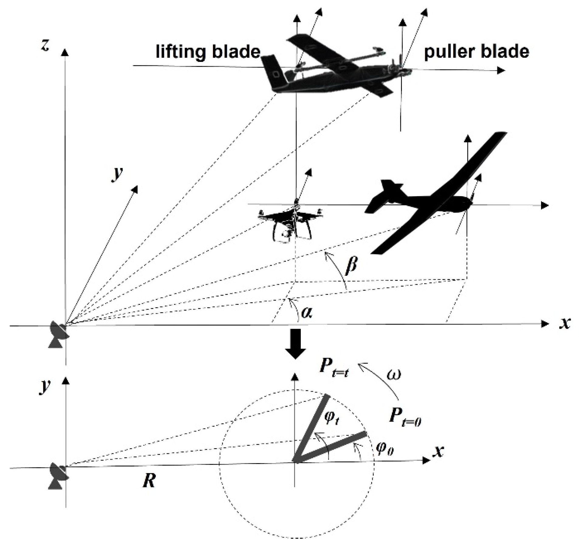
2.1. Scattering Model
2.2. Metrics
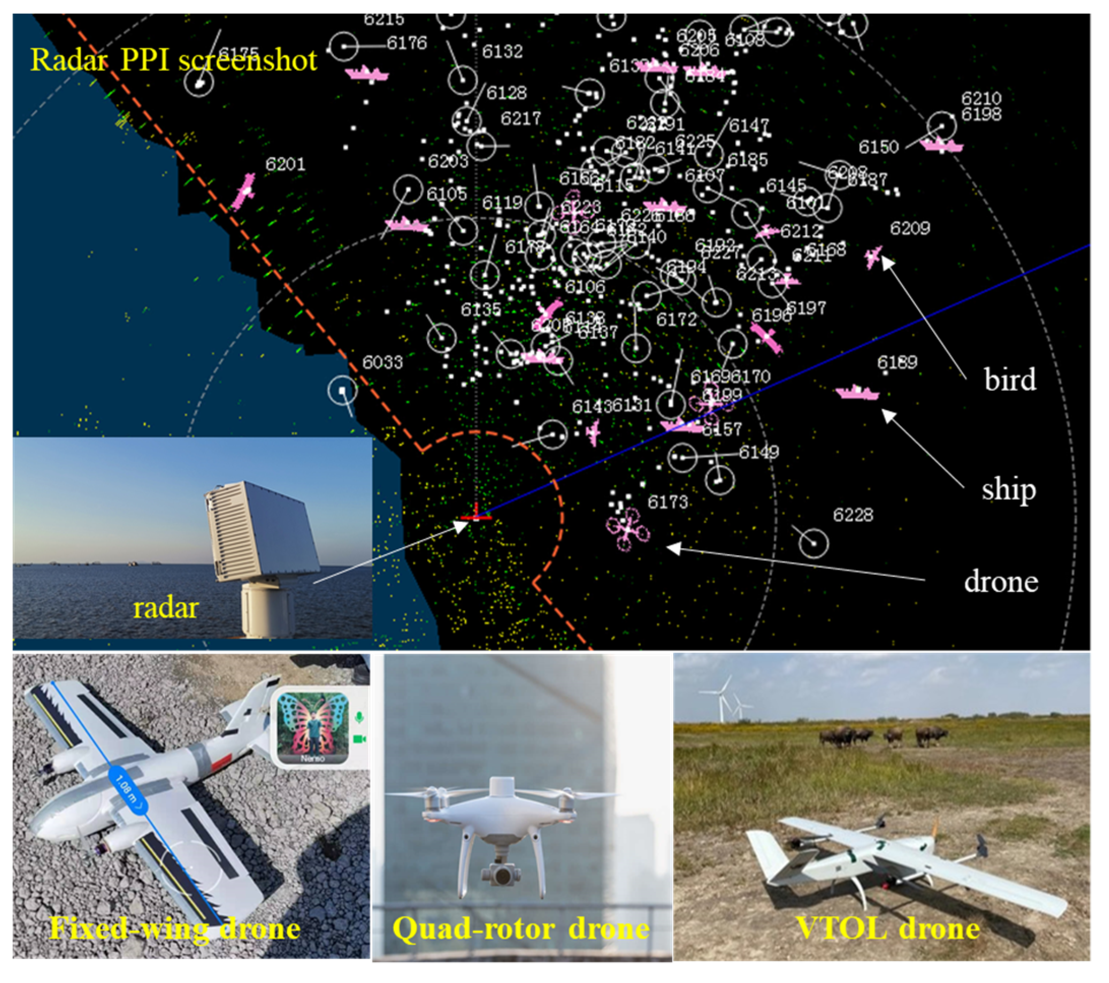
2.3. Experiments
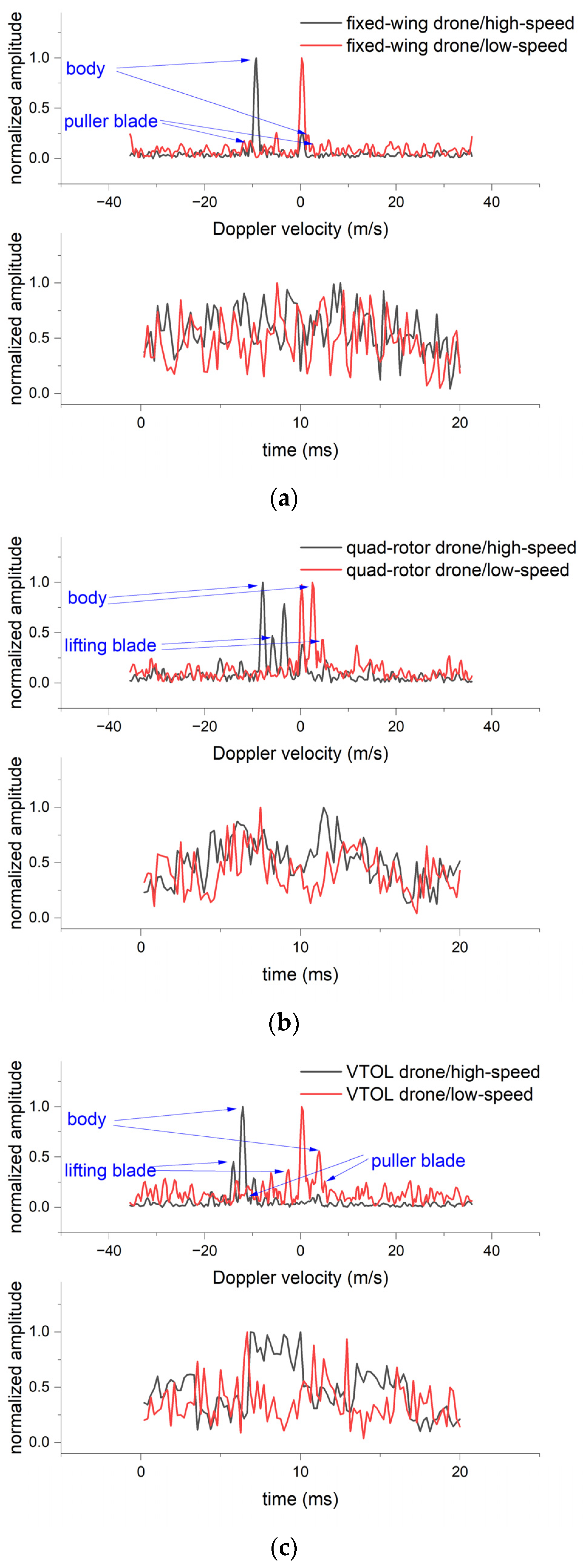
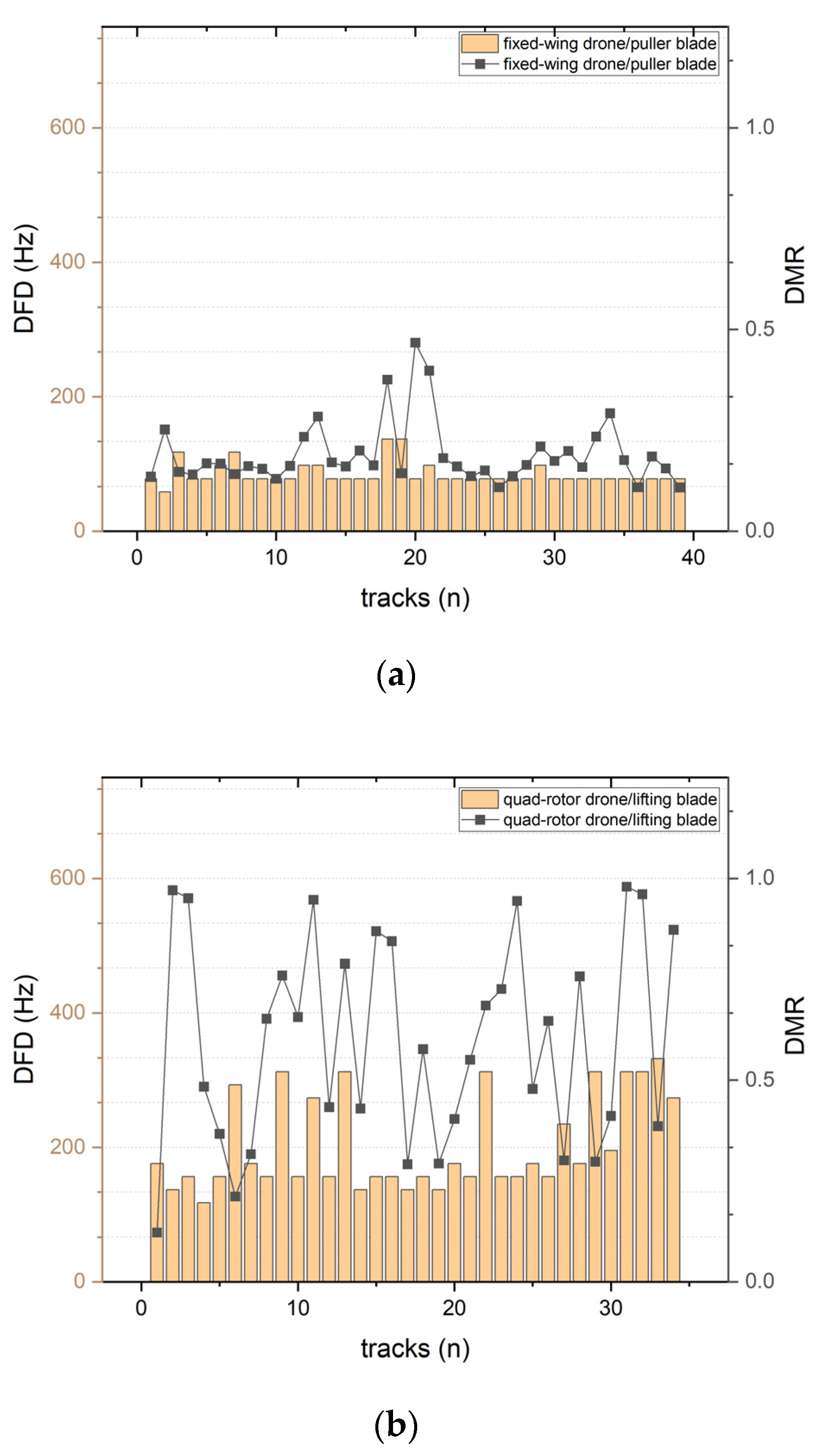
3. Results
4. Discussion
5. Conclusions
Author Contributions
Funding
Institutional Review Board Statement
Informed Consent Statement
Data Availability Statement
Acknowledgments
Conflicts of Interest
References
- Milas, A.S.; Cracknell, A.P.; Warner, T.A. Drones—The third generation source of remote sensing data. Int. J. Remote Sens. 2018, 39, 7125–7137. [Google Scholar] [CrossRef]
- Sun, Z.; Wang, X.; Wang, Z.; Yang, L.; Xie, Y.; Huang, Y. UAVs as Remote Sensing Platforms in Plant Ecology: Review of Applications and Challenges. J. Plant Ecol. 2021, 14, 1003–1023. [Google Scholar] [CrossRef]
- Petrovski, A.; Bogatinov, D.; Radovanović, M. Application of Drones in Crises Management Supported Mobile Applications and C4IRS Systems; Springer International Publishing: New York, NY, USA, 2023; pp. 321–334. ISBN 978-3-031-26753-6. [Google Scholar]
- Yang, B.; Li, J. A Hierarchical Approach for Refining Point Cloud Quality of a Low Cost UAV LiDAR System in the Urban Environment. ISPRS J. Photogramm. Remote Sens. 2022, 183, 403–421. [Google Scholar] [CrossRef]
- Semercioğlu, H. The New Balance of Power in the Southern Caucasus in the Context of the Nagorno-Karabakh Conflict in 2020. RS Res. Stud. Anatolia J. 2021, 4, 49–60. [Google Scholar]
- Kunertova, D. The War in Ukraine Shows the Game-Changing Effect of Drones Depends on the Game. Bull. At. Sci. 2023, 79, 95–102. [Google Scholar] [CrossRef]
- Ilić, D.; Tomašević, V. The impact of the Nagorno-Karabakh conflict in 2020 on the perception of combat drones. Serb. J. Eng. Manag. 2021, 6, 9–21. [Google Scholar] [CrossRef]
- Pong, B. The Art of Drone Warfare. J. War Cult. Stud. 2022, 15, 377–387. [Google Scholar] [CrossRef]
- Markarian, G.; Staniforth, A. Countermeasures for Aerial Drones; Artech: London, UK; Norwood, MA, USA, 2020. [Google Scholar]
- Clemente, C.; Fioranelli, F.; Colone, F.; Li, G. Radar Countermeasures for Unmanned Aerial Vehicles; IET: London, UK, 2021; ISBN 9781839531903. [Google Scholar]
- Wellig, P.; Speirs, P.; Schuepbach, C.; Oechslin, R.; Renker, M.; Boeniger, U.; Pratisto, H. Radar Systems and Challenges for C-UAV. In Proceedings of the International Radar Symposium 2018, Nanjing, China, 17–19 October 2018; Volume 2018, pp. 1–8. [Google Scholar]
- U.S. Army Unmanned Aircraft Systems Center of Excellence. Eyes of the Army. In U.S. Army Unmanned Aircraft Systems Roadmap 2010–2035; U.S. Army Unmanned Aircraft Systems Center of Excellence: Fort Rucker, AL, USA, 2010. [Google Scholar]
- Hanif, A.; Muaz, M.; Hasan, A.; Adeel, M. Micro-Doppler Based Target Recognition with Radars: A Review. IEEE Sens. J. 2022, 22, 2948–2961. [Google Scholar] [CrossRef]
- Rudys, S.; Ragulis, P.; Laučys, A.; Bručas, D.; Pomarnacki, R.; Plonis, D. Investigation of UAV Detection by Different Solid-State Marine Radars. Electronics 2022, 11, 2502. [Google Scholar] [CrossRef]
- Molchanov, P.; Harmanny, R.I.A.; De Wit, J.J.M.; Egiazarian, K.; Astola, J. Classification of Small UAVs and Birds by Micro-Doppler Signatures. Int. J. Microw. Wirel. Technol. 2014, 6, 435–444. [Google Scholar] [CrossRef]
- Molchanov, P.; Egiazarian, K.; Astola, J.; Harmanny, R.I.A.; de Wit, J.J.M. Classification of small UAVs and birds by micro-Doppler signatures. In Proceedings of the 2013 European Radar Conference, Nuremberg, Germany, 9–11 October 2013; pp. 172–175. [Google Scholar]
- Palamà, R.; Fioranelli, F.; Ritchie, M.; Inggs, M.; Lewis, S.; Griffiths, H. Measurements and discrimination of drones and birds with a multi-frequency multistatic radar system. IET Radar Sonar Navig. 2021, 15, 841–852. [Google Scholar] [CrossRef]
- Dale, H.; Jahangir, M.; Baker, C.J.; Antoniou, M.; Harman, S.; Ahmad, B.I. Convolutional Neural Networks for Robust Classification of Drones. In Proceedings of the 2022 IEEE Radar Conference (RadarConf22), New York, NY, USA, 21–25 March 2022; pp. 1–6. [Google Scholar]
- Dale, H.; Baker, C.; Antoniou, M.; Jahangir, M.; Atkinson, G.; Harman, S. SNR-Dependent Drone Classification Using Convolutional Neural Networks. IET Radar Sonar Navig. 2022, 16, 22–33. [Google Scholar] [CrossRef]
- Kang, K.-B.; Choi, J.-H.; Cho, B.-L.; Lee, J.-S.; Kim, K.-T. Analysis of Micro-Doppler Signatures of Small UAVs Based on Doppler Spectrum. IEEE Trans. Aerosp. Electron. Syst. 2021, 57, 3252–3267. [Google Scholar] [CrossRef]
- Chen, V.C. The Micro-Doppler Effect in Radar; Artech House: London, UK; Norwood, MA, USA, 2011; ISBN 9781608070572. [Google Scholar]
- Gong, J.; Li, D.; Yan, J.; Hu, H.; Kong, D. Comparison of Radar Signatures from a Hybrid VTOL Fixed-Wing Drone and Quad-Rotor Drone. Drones 2022, 6, 110. [Google Scholar] [CrossRef]
- Gong, J.; Yan, J.; Li, D. Comparison of micro-Doppler signatures registered using RBM of helicopters and WSM of vehicles. IET Radar Sonar Navig. 2019, 13, 1951–1955. [Google Scholar] [CrossRef]
- Chin, C.; Gopalakrishnan, K.; Egorov, M.; Evans, A.; Balakrishnan, H. Efficiency and Fairness in Unmanned Air Traffic Flow Management. IEEE Trans. Intell. Transp. Syst. 2021, 22, 5939–5951. [Google Scholar] [CrossRef]
- Chen, S.; Ma, D.; Yao, Y.; Wang, X.; Li, C. Cooperative Polynomial Guidance Law with Collision Avoidance and Flight Path Angle Coordination. Aerosp. Sci. Technol. 2022, 130, 107809. [Google Scholar] [CrossRef]
- Yu, J.; Dong, X.; Li, Q.; Lu, J.; Ren, Z. Adaptive Practical Optimal Time-Varying Formation Tracking Control for Disturbed High-Order Multi-Agent Systems. IEEE Trans. Circuits Syst. I Regul. Pap. 2022, 69, 2567–2578. [Google Scholar] [CrossRef]


| Category | Size | Maximum Gross Takeoff Weight (Pounds) | Normal Operating Altitude (ft) | Airspeed (Knots) |
|---|---|---|---|---|
| Group 1 | Small | 0–20 | <1200 Above Ground Level (AGL) | <100 |
| Group 2 | Medium | 21–55 | <3500 AGL | <250 |
| Group 3 | Large | <1320 | <18,000 Mean Sea Level (MSL) | |
| Group 4 | Larger | <1320 | Any airspeed | |
| Group 5 | Largest | >1320 | >18,000 MSL | Any airspeed |
| Drone Type | Fixed-Wing Drone | Quad-Rotor Drone | VTOL Drone | |
|---|---|---|---|---|
| Model | Albatross1 | Phantom 4 | TX25A | |
| Manufacturer | Homemade | DJI Inc. | Harryskydream Inc. | |
| Flight weight (kg) | 0.3 | 1.38 | 26 | |
| Body size (cm) | 80 | 40 | 197 | |
| Wingspan (cm) | 108 | 40 | 360 | |
| Cruise speed (m/s) | 10 | 15 | 25 | |
| Blades | lifting | 0 | 4 | 4 |
| puller | 1 | 0 | 1 | |
| Blade length(cm) | 10 | 20 | 30 | |
| Aero-frame materials | EPP (Expanded polypropylene) | PC (Polycarbonate) | FRP (Fiber-reinforce plastic) | |
| Object | Fixed-Wing Drone | Quad-Rotor Drone | VTOL Drone | ||
|---|---|---|---|---|---|
| Tracking distance (km) | 11~12 | 10~11 | 9~13 | ||
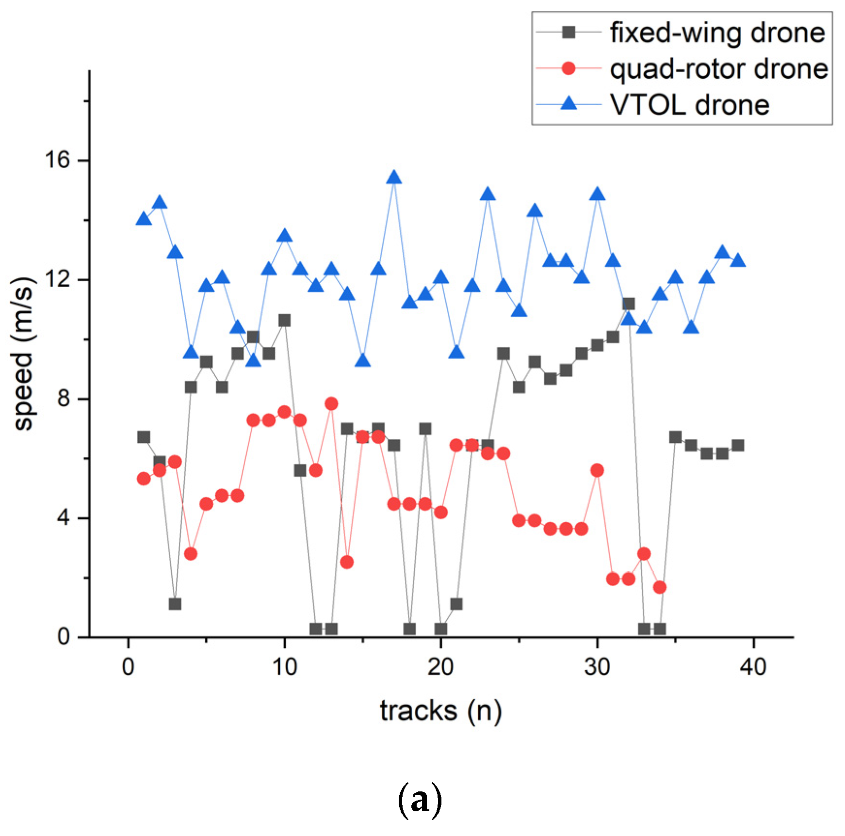
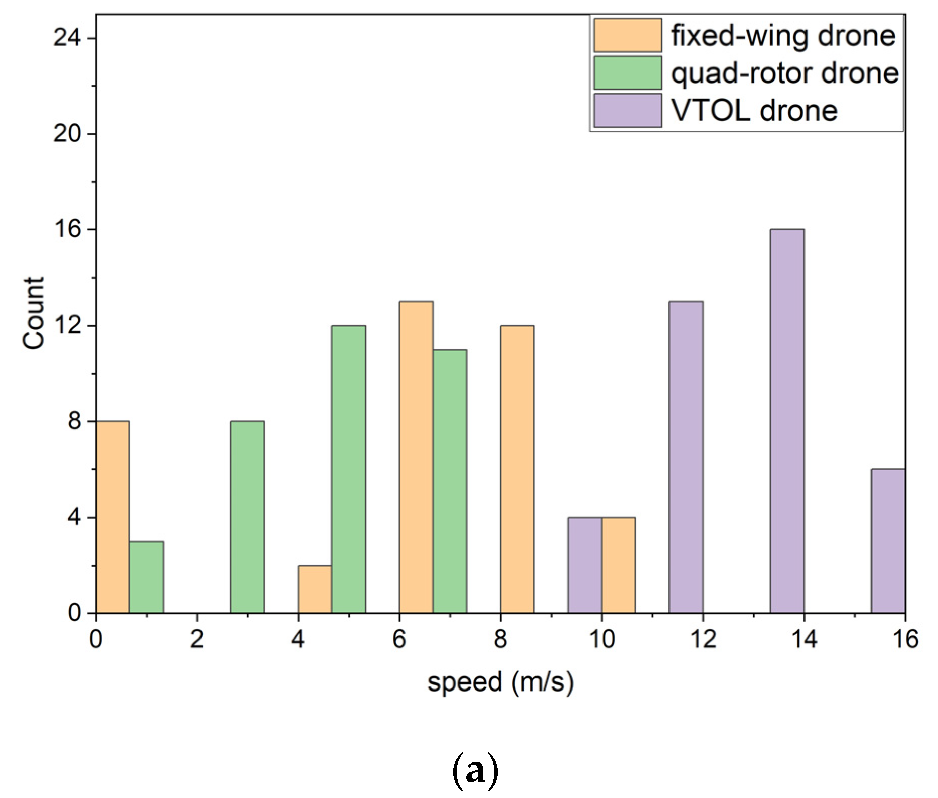
| Velocity (m/s) | Mean | 6.46 | 4.94 | 12.04 | |
| Range | 10.92 | 6.16 | 6.16 | ||
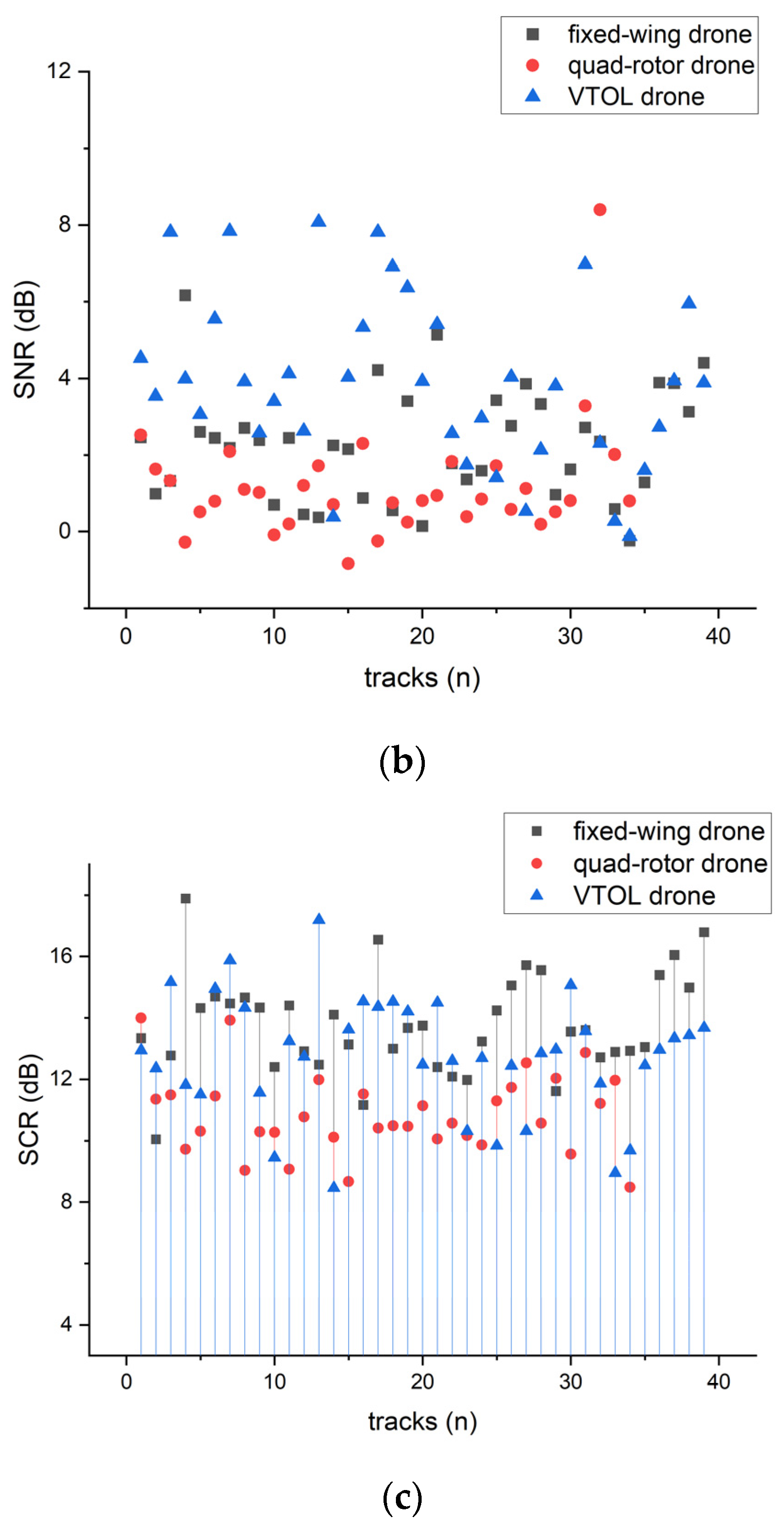
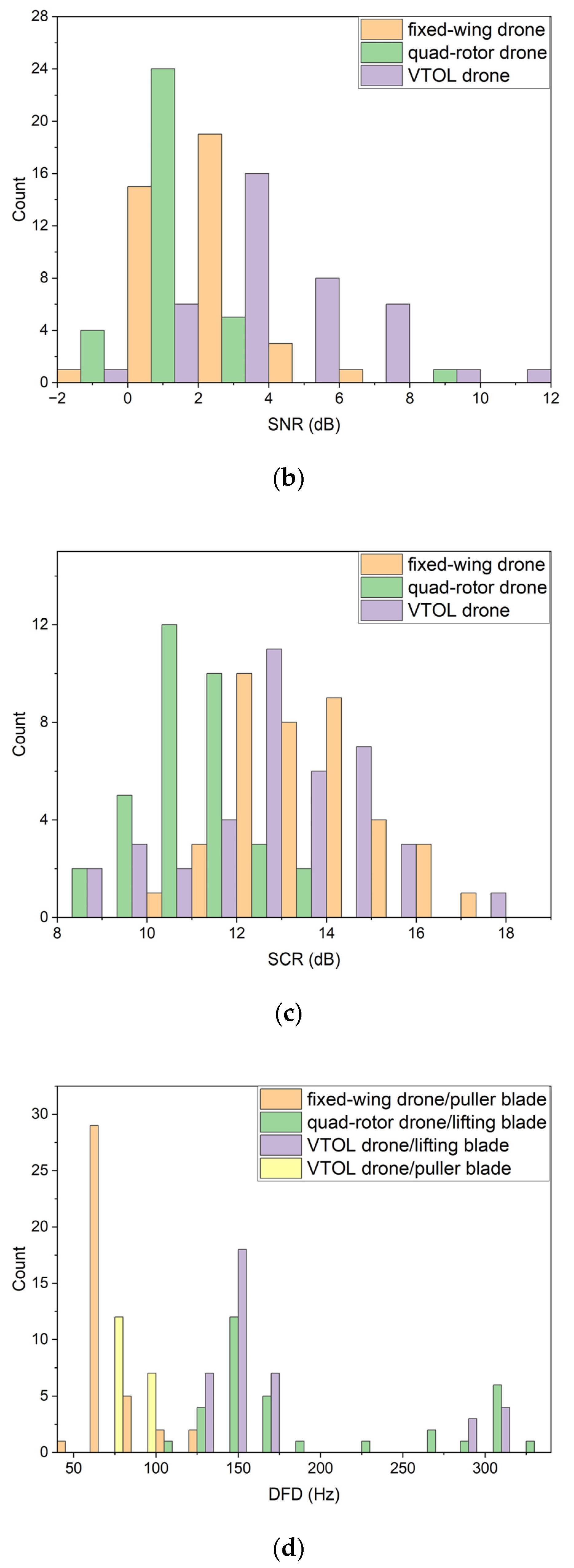
| SNR (dB) | Mean | 2.27 | 1.20 | 4.07 | |
| Range | 6.4 | 9.23 | 11.21 | ||
| SCR (dB) | Mean | 13.79 | 10.86 | 12.79 | |
| Range | 7.84 | 5.51 | 8.73 | ||
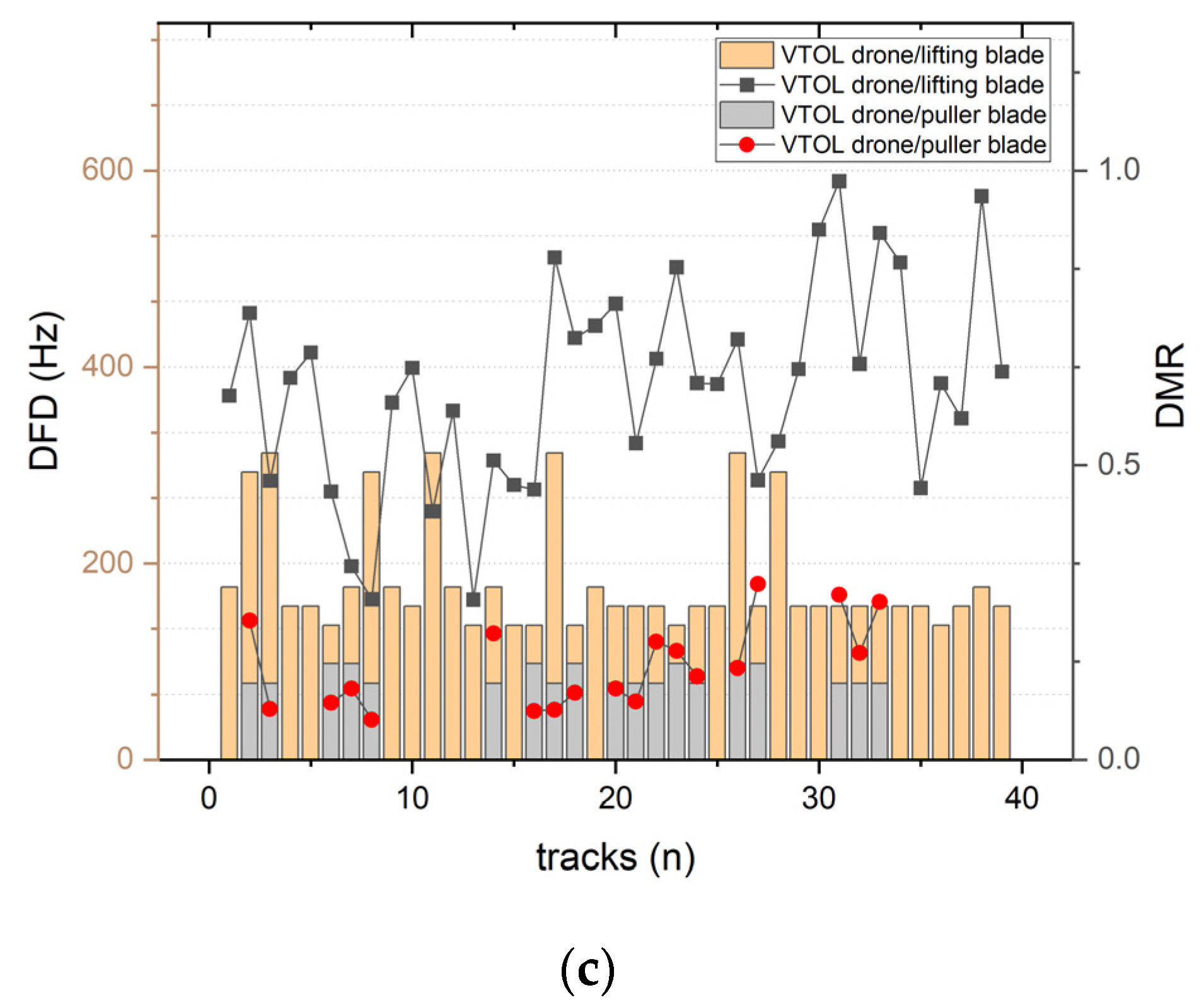
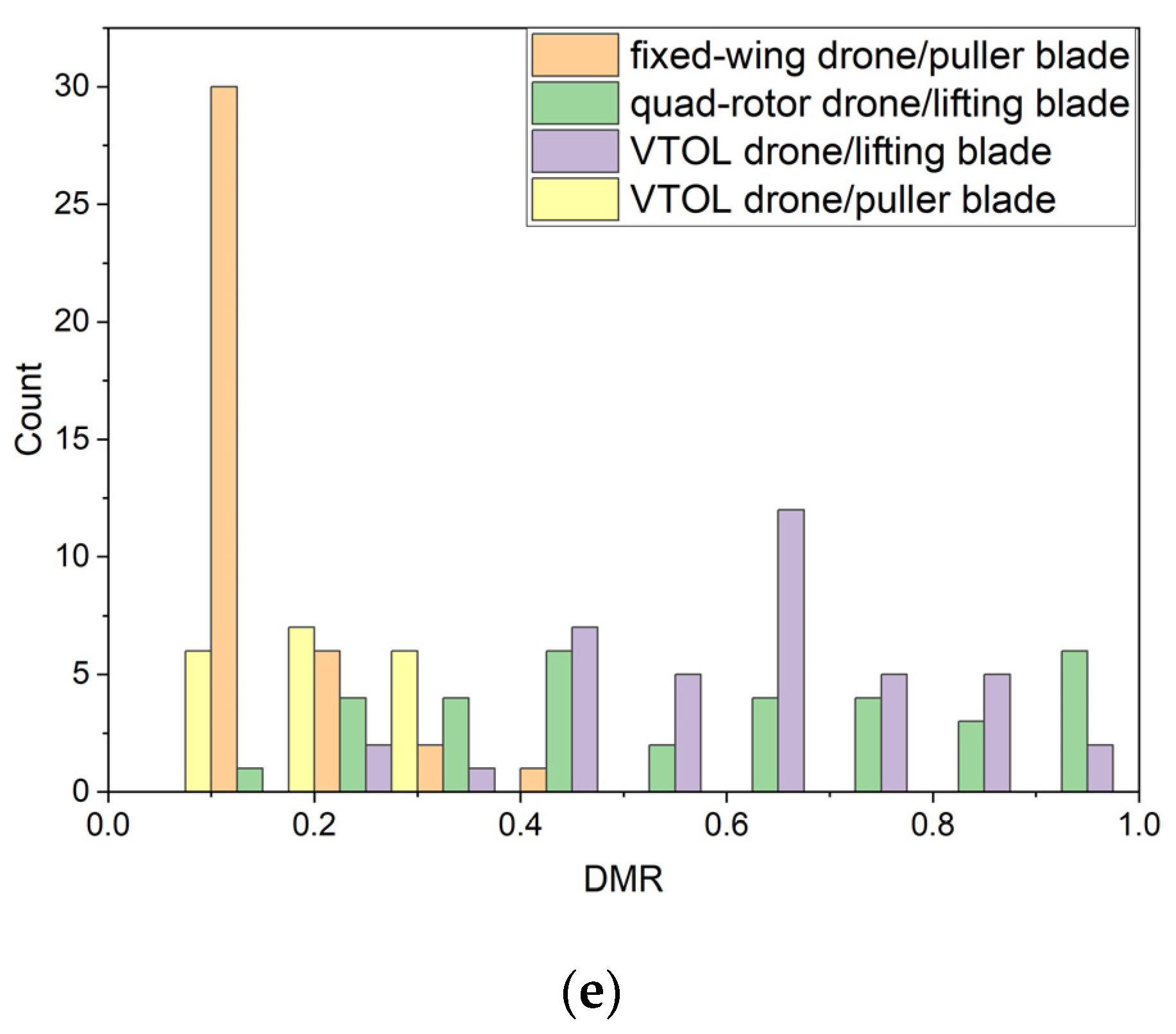
| Blade | Puller blade | Lifting blade | Puller blade | Lifting blade | |
| DFD (Hz) | Mean | 85.13 | 202.76 | 85.31 | 182.78 |
| Range | 78.12 | 214.83 | 19.53 | 175.77 | |
| DMR | Mean | 0.18 | 0.59 | 0.15 | 0.63 |
| Range | 0.35 | 0.85 | 0.23 | 0.71 | |
Disclaimer/Publisher’s Note: The statements, opinions and data contained in all publications are solely those of the individual author(s) and contributor(s) and not of MDPI and/or the editor(s). MDPI and/or the editor(s) disclaim responsibility for any injury to people or property resulting from any ideas, methods, instructions or products referred to in the content. |
© 2023 by the authors. Licensee MDPI, Basel, Switzerland. This article is an open access article distributed under the terms and conditions of the Creative Commons Attribution (CC BY) license (https://creativecommons.org/licenses/by/4.0/).
Share and Cite
Yan, J.; Hu, H.; Gong, J.; Kong, D.; Li, D. Exploring Radar Micro-Doppler Signatures for Recognition of Drone Types. Drones 2023, 7, 280. https://doi.org/10.3390/drones7040280
Yan J, Hu H, Gong J, Kong D, Li D. Exploring Radar Micro-Doppler Signatures for Recognition of Drone Types. Drones. 2023; 7(4):280. https://doi.org/10.3390/drones7040280
Chicago/Turabian StyleYan, Jun, Huiping Hu, Jiangkun Gong, Deyong Kong, and Deren Li. 2023. "Exploring Radar Micro-Doppler Signatures for Recognition of Drone Types" Drones 7, no. 4: 280. https://doi.org/10.3390/drones7040280