Article

Design Procedure of a Low-Cost System for Energy Replenishment in a Quadrotor UAV through a Battery Exchange Mechanism

by
Yair Lozano-Hernández
1,†,
Ismael Martínez de la Cruz
2,†,
Octavio Gutiérrez-Frías
2,*,†,
Norma Lozada-Castillo
2,*,† and
Alberto Luviano-Juárez
2,*,†
1
Instituto Politécnico Nacional, Mecatrónica, Unidad Profesional Interdisciplinaria de Ingeniería Campus Hidalgo (UPIIH), Hidalgo 42162, Mexico
2
Instituto Politécnico Nacional, Unidad Profesional Interdisciplinaria en Ingeniería y Tecnologías Avanzadas, Mexico City 07340, Mexico
*
Authors to whom correspondence should be addressed.
These authors contributed equally to this work.
Drones 2023, 7(4), 270; https://doi.org/10.3390/drones7040270
Submission received: 9 March 2023 / Revised: 10 April 2023 / Accepted: 13 April 2023 / Published: 15 April 2023

Abstract

:
This paper describes the design and construction of an energy replenishment service station for a quadrotor. The prototype includes a small number of actuators, making it a low-cost solution. The system consists of three batteries: two charged and one discharged (within the quadrotor). Once the quadrotor lands, the battery with the highest charge is selected, which is then exchanged for the discharged battery. In order to perform this action, position control is used, in which the desired value depends on the location of the sensor that detects the highest voltage. In addition, the system has a mechanical design that facilitates the coupling of the unmanned aerial vehicle (UAV) with the structure for battery exchange, ensuring that the discharged battery is always in the same position. Furthermore, the design of a mechanism to release and hold the battery placed in the quadrotor is presented, which works by means of voltage and force sensors that identify the instant that the battery is discharged and when the UAV has landed on the exchange platform, thus initiating the exchange process. Likewise, the criteria for selecting the elements used, acquiring and processing signals, and routines for changing batteries are detailed.

1. Introduction

In recent years, unmanned aerial vehicles (UAV) have been utilized in various applications, both civil and military. They have attracted the attention of researchers in different areas, including automatic control, robotics, mechatronics, and mechanics, among others [1,2,3,4]. In particular, rotary-wing UAVs have been used in various applications, for example, filming sports events, agriculture, search and rescue, military applications, cartography, and photogrammetry, to name a few.
Despite the large amount of research and applications, there are still areas of opportunity for these vehicles, particularly their low-energy autonomy and downtime when the battery is charging. One of the most popular rotary-wing UAVs is the quadrotor. However, few commercial quadrotor models can exceed a flight time of at least 20 min due to their nature, requiring a high supply of electrical energy for operation [5,6].
Most small UAVs—especially quadrotors—use lithium polymer (LiPo) batteries [5,7,8]. In fact, LiPo batteries power almost 90% of UAVs with a weight and length less than 2 kg and 100 cm, respectively [1,9]. It should be noted that the battery is the main component hindering the development of tasks that require long flight times. For these operations, a qualified operator is required to replace the batteries, when necessary [10].
In particular, quadrotors have had a great impact at the commercial level, due to the number of applications in which they have been integrated; however, there still exists a need to incorporate them into activities in which the flight time represents a determining factor. For this reason, the scientific community has been searching for profitable, safe, and fast ways to recharge UAVs, highlighting proposals for contact charging, battery change, fuel cells, and supercapacitors [11].
Charging stations are a good option when coverage is low; otherwise, it is preferable to use exchange stations [9]. For this reason, there is a need to design and build autonomous refueling systems for UAVs, that is, service stations capable of recharging and exchanging quadrotor batteries without human intervention.
In relation to the above, works such as the one presented in [12] have focused on the design of platforms for the automatic changing of batteries for multiple UAV agents. Their proposed station can recharge eight batteries simultaneously: the prototype performs the exchange in direct form, reducing losses and downtime in surveillance maneuvers carried out in controlled environments.
In [13], the development of an autonomous charging station system for a quadrotor for use in multi-agent aerial surveillance maneuvers is described, in which control was achieved by using adaptive algorithms. The results allowed the effective flight time to be increased by almost 300 % , leaving improvement of the control algorithm in order to be able to accommodate more UAVs into the system as future work.
For their part, Lee et al. [14] presented a proposal for an autonomous quadrotor battery exchange system using a platform placed on the ground, thus reducing vehicle downtime. The exchange is carried out under conditions that do not allow for data loss or deconfiguration during the process exchange. The proposed prototype works with four batteries—three fully charged and one exhausted—and it should be noted that the work cited above does not contemplate the problem of battery charging, only addressing the exchange of batteries.
The authors of [3] developed an automatic battery change mechanism, called “endless flyer”, in which the battery change process is performed after the UAV lands on the platform. The UAV moves to the center of the platform, where the exchange takes place. In [15], an exchange system which uses a servo-based mechanism to change and place the batteries in a horizontally mounted hexagonal sphere was proposed, which holds the batteries in charge.
Other technologies for charging and/or power supply include wireless, laser beam in-flight charging, hydrogen cells, and solar power [9]. Wireless is an alternative for energy harvesting, but, as the amount of energy that can be transferred is reduced, it is used mainly for low-consumption devices [16].
In [17], a method for wireless charging of a UAV after landing without the necessity of replacing the battery is presented. A frequency of 5.9 GHz was used, but a disadvantage is that the maximum DC output power in 3.9 mW. Furthermore, in [18,19], the authors showed that it is possible to use the energy of an overhead power line to recharge a UAV while it is used for power line inspection; however, the idea is currently under development.
The laser beam in-flight recharge approach forces the UAV to operate at limited heights and areas in order to maintain energy transfer from the laser transmitter. Furthermore, a laser transmitter is required for each UAV, which implies that an increase in the number of UAVs to be used considerably increases the cost of the system [9,20].
Hydrogen-powered UAVs can fly for hours, and the re-fueling process requires less time compared to LiPo batteries. However, being a niche product, they are more expensive than LiPo batteries [21]. Fuel cells can reach an efficiency close to 60% [22], which is lower than that of LiPo batteries (above 90%). In addition, the use of a fuel cell requires auxiliary equipment, which further reduces the efficiency.
Finally, solar-powered UAVs must have large wings to maximize the amount of light energy received, which limits their use to fixed-wing UAVs.
Most of the methods described above present operational difficulties, complicated construction requirements, the need for physical assistance, and may even raise serious concerns about human injuries and electrical hazards during their operation [11].
Proposals based on charging or exchanging batteries tend to have the fewest complications regarding their integration into our daily life activities; furthermore, refueling stations are economically superior in low target coverage scenarios, while for high-coverage systems, swap stations perform better [23].
Considering the above-mentioned research, a need to develop systems that allow for the charging and exchanging of batteries in less time and at an affordable cost was observed. For example, in [2], the authors proposed a system that can charge various batteries; however, their system has inadequate dimensions for practical applications, and lacks a control scheme for the exchange. In [3], a system with only a mechanism for the exchange was presented, which has the disadvantage that the system requires one minute for the battery exchange.
In [14], an exchange system with a maximum time of 60 s for the exchange process is presented; however, this system requires an external source to avoid the loss of on-board data. For more information on other advances related to the exchange and charging of batteries for UAVs, it is recommended that the reader consults [24,25,26], among other studies.
The cited works described each of their proposals; however, they did not detail the methodology used for the design and construction. It should be noted that there are no general design methodologies for this type of system, which is of great relevance at present. Thus, this paper provides the methodology and process behind the design, construction, and instrumentation of a low-cost service station for energy replenishment in a quadrotor (S-SERQ). This system comprises three key elements: the landing structure (LS), battery exchange mechanism (BEM), and the battery release/clamp mechanism.
The S-SERQ is designed for outdoor use with limited access to electrical power sources or with the future incorporation of alternative energies (e.g., solar or wind) in mind. Our prototype includes a reduced number of sensors and actuators, which reduces energy consumption during the battery exchange process.
This design reduces the presence of disturbances during the landing of the Quadrotor over the service station and facilitates the coupling of the Quadrotor with the station (despite oscillations of ± 0.3 rad in the y a w angle). Moreover, a finite element analysis (FEA) is conducted to ensure that there are no deformations in the prototype, which could complicate the battery exchange process. Once the quadrotor is over the LS, battery exchange is carried out by controlling the position of the BEM, which is achieved by the use of a PID control, where the reference value depends on the position of the most-charged battery.
The acquisition and conditioning of signals present in the S-SERQ is conducted through the Simulink MATLAB Waijung blockset. The station can also achieve battery exchange in less than 10 s, which prevents the quadrotor from losing its settings. Thus, the key contribution of this work is a detailed description of the criteria and design process for this type of station, which can be used as a basis for the development of future complex energy replacement systems.
The remainder of this paper is organized as follows: Section 2 describes the technical considerations for the design of the service station, including the results of an FEA applied to the points of the structure that are susceptible to plastic deformation. Section 3 presents the instrumentation of the system, including details of the acquisition and conditioning of signals.
In Section 4, a selective control scheme based on a PID algorithm with a variable reference value (which changes depending on the position of the most-charged battery) is described [27]. Additionally, Section 4 highlights the experiments and results for the control scheme. Section 5 presents a discussion of results, while the final section discusses the conclusions obtained from this work.

2. Design Considerations

The service station was designed based on the requirements of the 3D Robotics quadrotor X4 Quad-C (marketed in 2014), which weighs 3.5 kg and uses a four-cell LiPo battery that delivers a voltage of 14.8 V and a current of 5.2 A. In addition, we assumed that the UAV has a control algorithm that compensates for the disturbances and aerodynamic effects present during landing. It is assumed that the UAV has the ability to land on the structure with a controlled descent speed and that the oscillations in y a w ( ψ ) are limited to ±0.3 rad. The above conditions can be achieved by using control algorithms, such as those reported previously [4,28,29]. Based on the above, the design criteria for the prototype were as follows:
  • A design that facilitates coupling of the UAV with the LS (oscillations of ± 0.3 rad in y a w angle) and reduces the presence of aerodynamic effects during landing (e.g., compressed air between the quadrotor and the ground [4]);
  • A mechanism that performs the battery exchange in less than 10 s, thus avoiding re-configuration of the electronic speed controllers (ESCs);
  • Low quantity of actuators and sensors, in order to reduce energy consumption;
  • The use of low-cost, low-energy sensors to know when the quadrotor has landed on the structure and battery exchange is required;
  • A mechanism to release/clamp the battery quickly and safely, with low energy consumption and which is easy to condition to other quadrotors.
Figure 1 shows the general scheme of the S-SERQ. It should be noted that the problem of autonomous landing on the service station is not considered here.

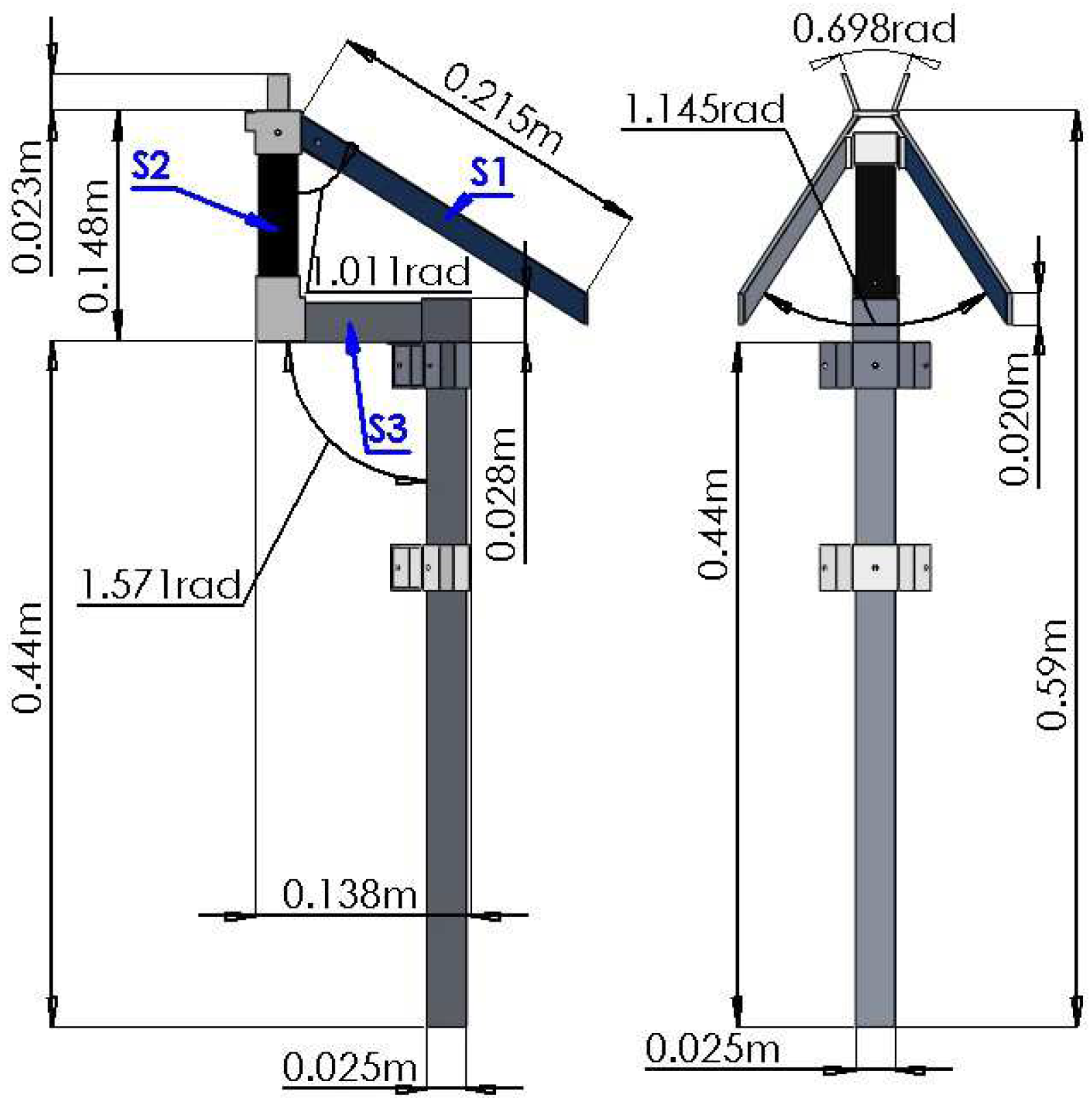
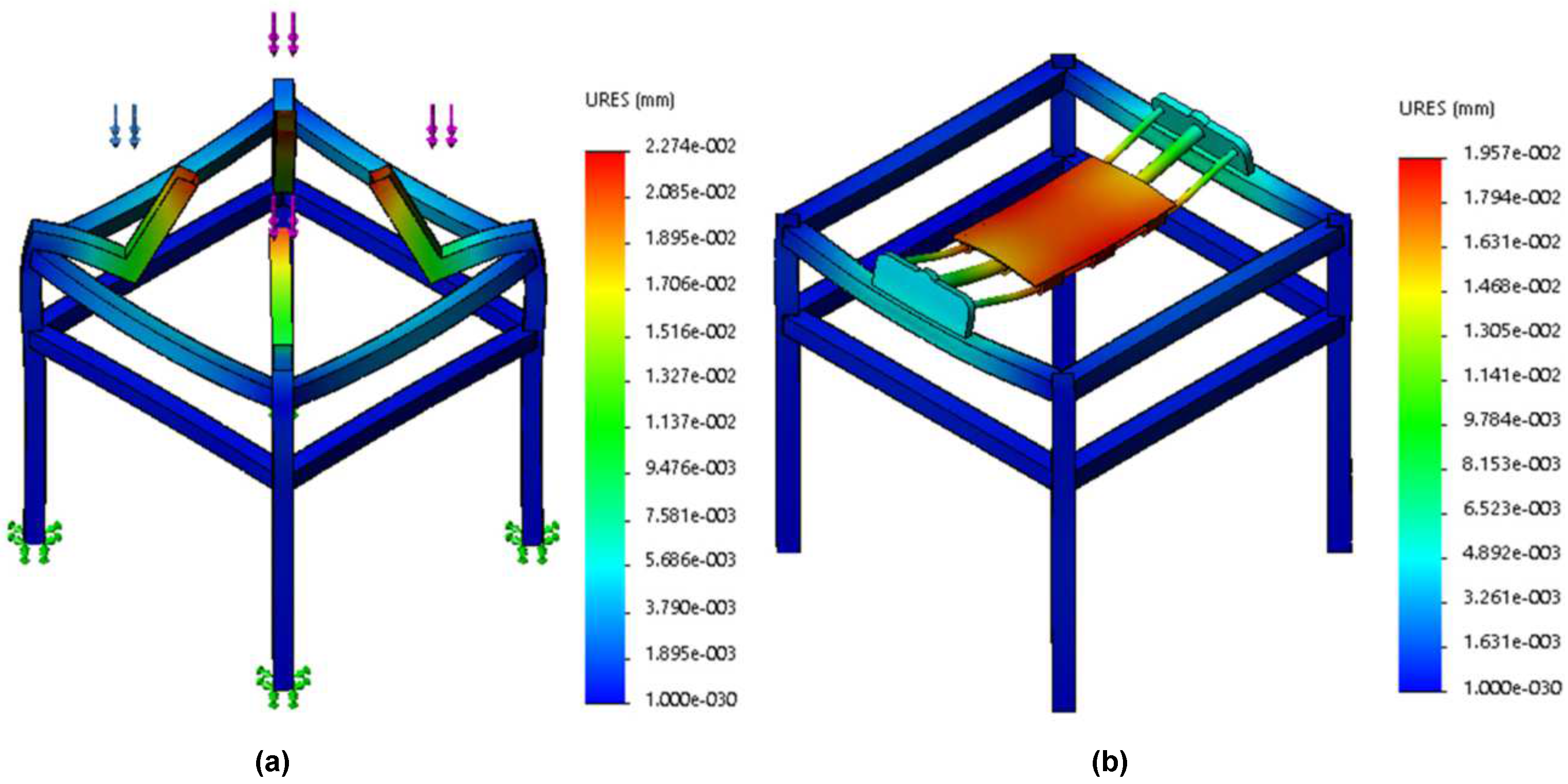
2.1. Landing Structure

Figure 2 shows the LS with the BEM. The landing points ( F 1 ,   F 2 ,   F 3 ,   F 4 ) have inverted V-shaped parts (see Figure 3) and are based on ideas previously reported in works such as [30,31]. Our approach acts as a mechanical guide, allowing for the quick and easy landing of the quadrotor on the LS. This design satisfies the following requirements:
  • No active components: The mechanism does not consume energy.
  • Battery aligned with the BEM: The discharged battery is always above the home position.
  • Precision Landing: Decreases the required accuracy in yaw angle control ( ψ ) during landing.
In summary, once the UAV is within the structure, it is attracted toward the center, facilitating the coupling of the quadrotor with the structure. Thus, an error margin of approximately ±0.3 rad is obtained during landing, and movement is restricted as the quadrotor approaches the center of the structure, thus placing it in the center of the platform. Therefore, the need for an actuator for coupling the quadrotor with the station is reduced.
The length of part S1 and the angle of 1.01 rad formed by parts S1 and S3 were designed based on the dimensions of each arm of the quadrotor and the characteristics of its legs. Thus, oscillations in ψ are allowed during landing. A height of 0.59 m was proposed for the structure, with holes/ducts to reduce the effects of disturbances due to the blockage of airflow into the propellers and the interaction between the UAV and the ground during landing (air mattress) [4,28]. The effects of blockage are the result of mutual interference between the propeller and the fuselage (in this case, the ground) and are composed of two effects: the “body interference effect” and the “scrubbing effect” [32].
Thus, the proposed S-SERQ facilitates the coupling of the system despite variations of ±0.3 rad in ψ , requiring a controlled descent speed (linear); that is, once the UAV is positioned above the LS and within the inverted V-shaped structure, it must land with the following rate of descent [33]:
d z = ( a E + b ) d t ,
where E is the error, b is the maximum desired descent rate, b / a is the maximum permissible error, and d t is the time between iterations.
To verify that there are no deformations due to the weight of the quadrotor and to determine the maximum force that the structure can withstand before presenting plastic deformation, an FEA was performed on the points that hold the quadrotor during the battery exchange ( F 1 ,   F 2 ,   F 3 ,   F 4 ). The analysis was conducted in the SolidWorks Computer-Aided Design (CAD) software, using tetrahedral elements to mesh the geometry [34].
The 6061 T52 aluminum alloy was used to manufacture the structure. As the quadrotor is parked at four points and considering that the weight is symmetrical, each point supports a force equivalent to 8.584 N. Figure 4 shows the results obtained with respect to the vertical displacement and von Mises element stress (see Figure 4a). A safety factor of 20% was considered, having a design force of 10.3 N at each support point, obtaining a maximum stress of 3.759 × 10 6 N m 2 (3.759 MPa). The selected material has a yield stress of 110 MPa; therefore, the structure met the design requirements.
Similarly, deformation analysis ( ε ) was carried out on the pieces that support the ends of the quadrotor, defined as follows [35]:
ε = L f L i L i ,
where L f is the final length and L i the initial length.
The results in Figure 4b show the deformation effect, which mainly affects the part of the structure that is in direct contact with the ground. The maximum deformation is equivalent to 0.00604 % , which can be considered negligible.
As mentioned above, the yield stress of the selected material was much greater than the maximum stress present; however, it is important to consider the maximum permissible vertical deformation. Therefore, a maximum allowable displacement of 0.5 mm was proposed in order to ensure the proper functioning of the exchange mechanism. Furthermore, a minimum safety factor of 38.57 was obtained, indicating that the structure can withstand a force of approximately 397.29 N, requiring 40.499 kg of weight to generate such a force.

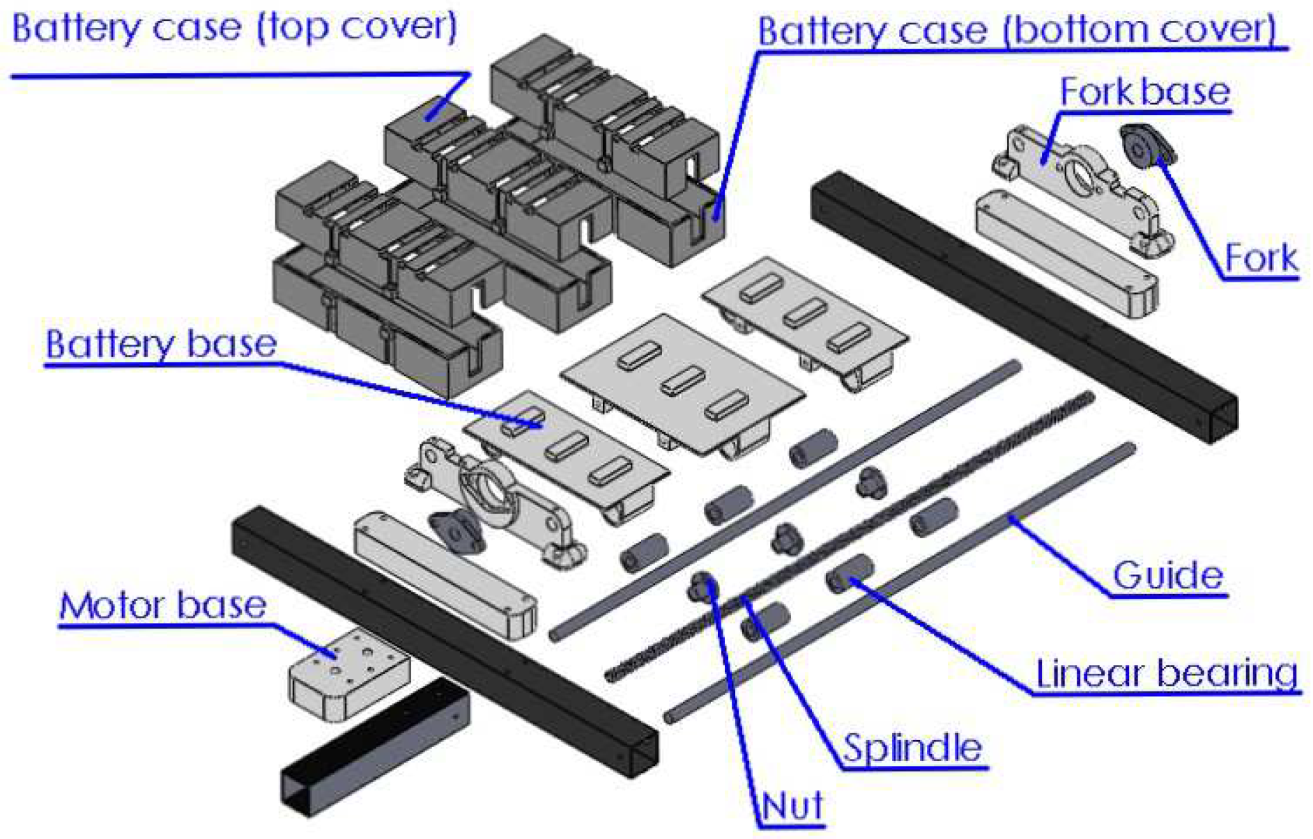
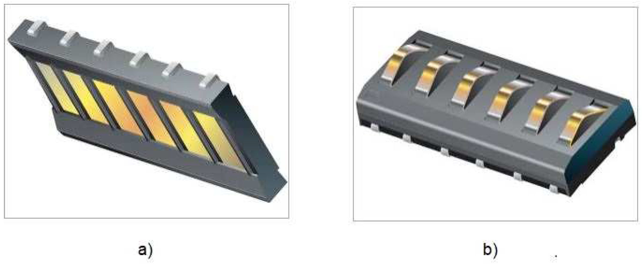
2.2. Battery Exchange Mechanism

The battery exchange is performed by a transmission system consisting of a spindle, six linear bearings, two bearings, and two guides (see Figure 5). This mechanism is responsible for moving the most-charged battery to the required position such that it can replace the current battery. It should be noted that the system can only work with three batteries: two charged and one within the quadrotor. Furthermore, it is important to mention that the battery exchange should not take more than 10 s; otherwise, the calibration of the ESC will be lost and the system must be manually restarted.

2.2.1. BEM Features

One of the primary factors for the design of the mechanism is the battery used in the drone, as it dictates the system requirements. The design parameters for the BEM are provided in Table 1.
As noted in the table above, the mechanism requires a working margin of 0.35 m. Therefore, a 0.45 m-long stainless-steel screw (8 mm diameter and 2 mm pitch) was selected. For the movement of batteries, three bronze nuts are used (internal diameter of 8 mm, pitch of 2 mm). The combination of the screw and nuts allows a linear displacement of 0.81 cm to be obtained for each turn of the screw, requiring 12.35 revolutions for a 10 cm displacement.

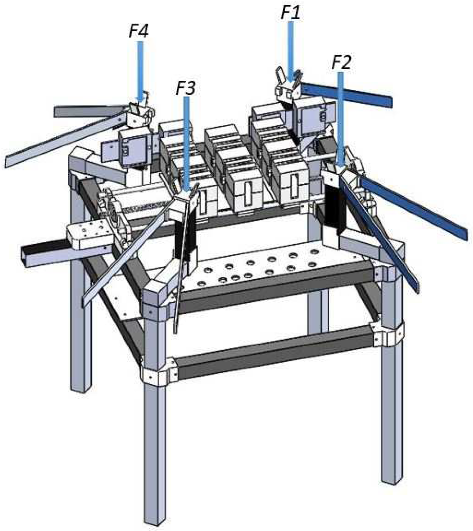
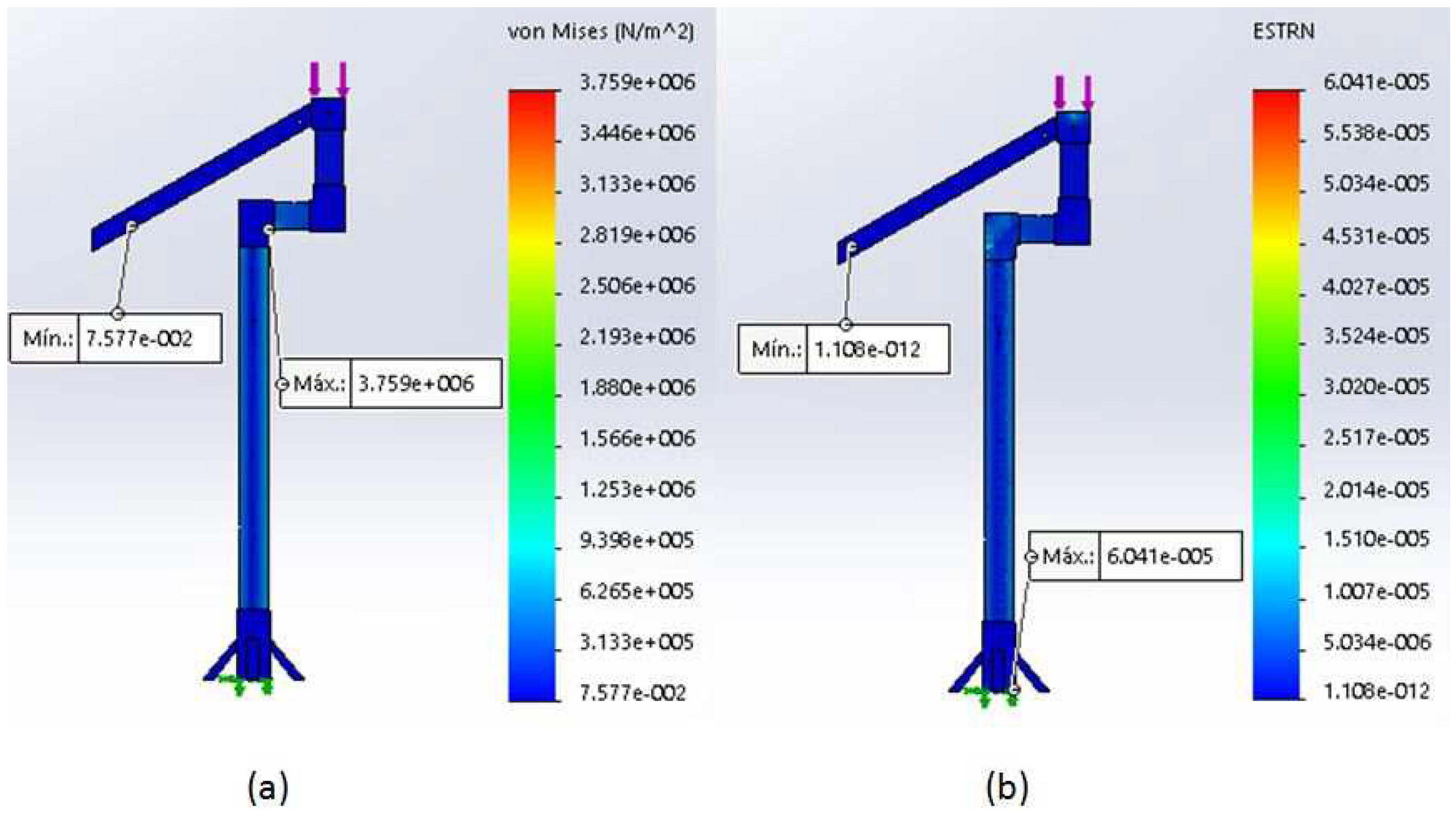
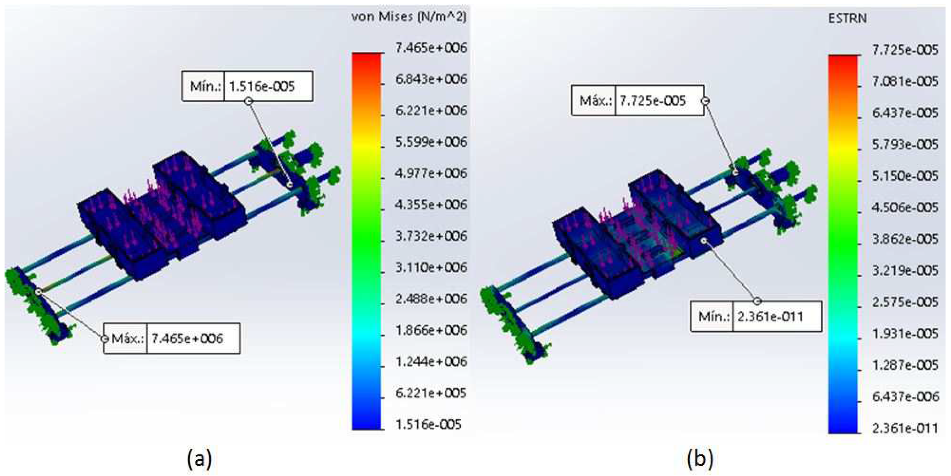
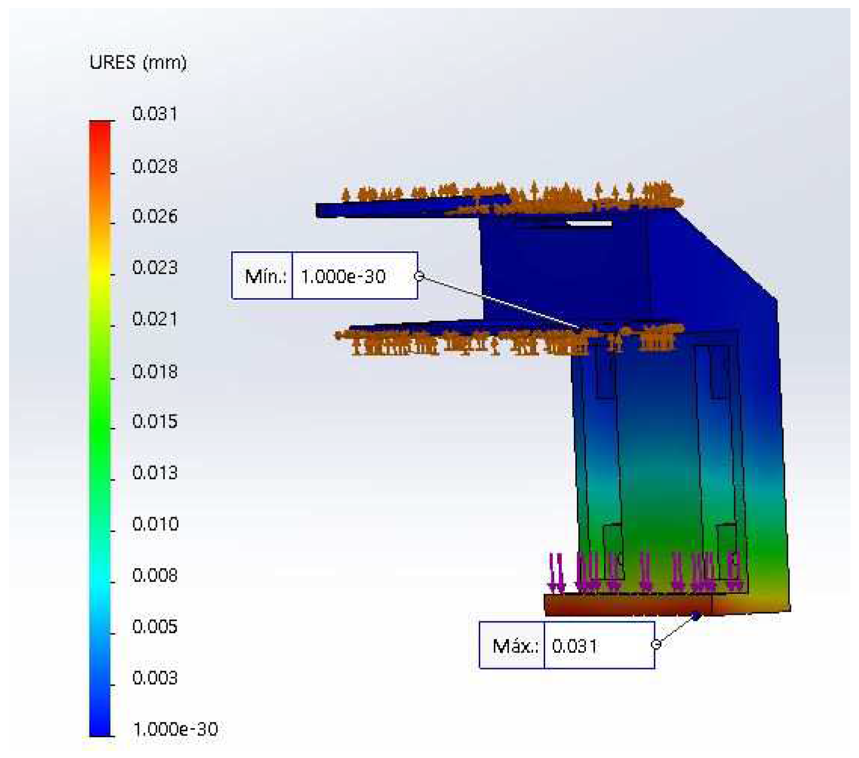
2.2.2. FEA in the BEM

The presence of vertical deformations can complicate the battery exchange. Therefore, FEA was performed. The force exerted by each of the batteries when placed on the system was utilized. Three batteries with weight of 500 g and a safety factor of 20% were considered, resulting in a design force of 5.886 N for each battery.
The results demonstrated a maximum stress and deformation of 7.465 MPa (see Figure 6a) and 0.00772% (see Figure 6b), respectively. Regarding the maximum deformation, the percentage obtained was negligible. A minimum safety factor of 23.09 was obtained, located at the connection of the spindle to the fork, allowing for the conclusion that the mechanism can support a maximum weight of 41.562 Kg. Finally, the maximum system displacement in the vertical axis is 0.05 mm, guaranteeing the absence of deviations that may affect or prevent the battery exchange.
Finally, a finite element analysis simulation of the structure was conducted, giving priority to two vertical forces applied at different points: the first on the four arms that support the drone device (see Figure 7a), and the second on the mobile table that carries the interchangeable batteries. The force applied to each arm was 8.584 N, distributed over the transverse face of each of the hollow square profiles. On the movable table (BEM), the action of a force distributed (17.658 N) over the entire surface of the movable table was considered (see Figure 7b). Both analyses indicated that there were no deformations that could affect the battery exchange.
In other words, the design proposal does not present problems that complicate the performance of the prototype (displacements greater than 0.5 mm) or, in extreme cases, cause plastic deformations. It should be noted that, at the time of manufacture of the prototype, the shapes and dimensions for the structure suffered small variations; however, the experiments carried out demonstrated that the design remained functional, even with such possible variations.

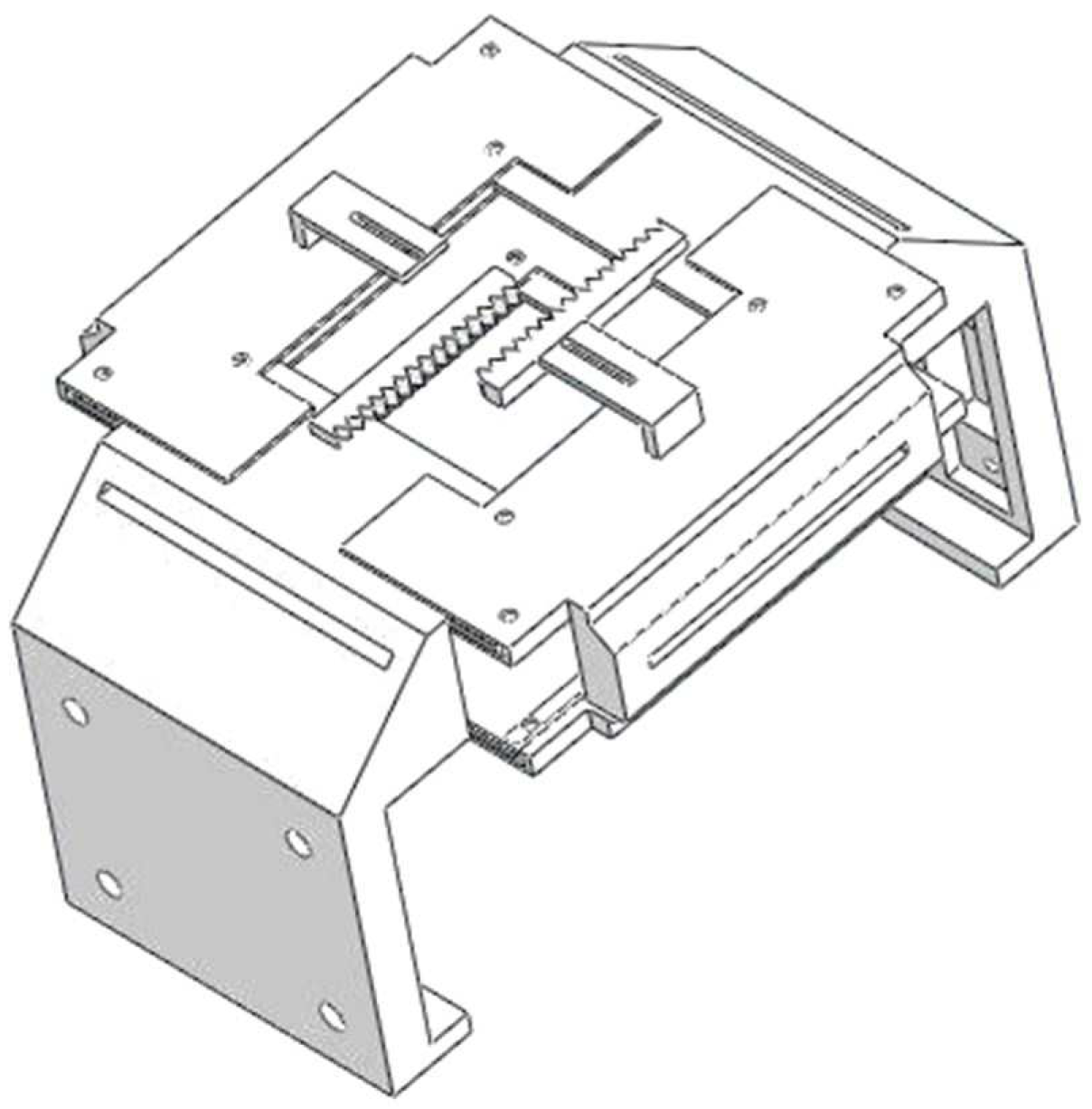
2.3. Battery Release/Clamp Mechanism
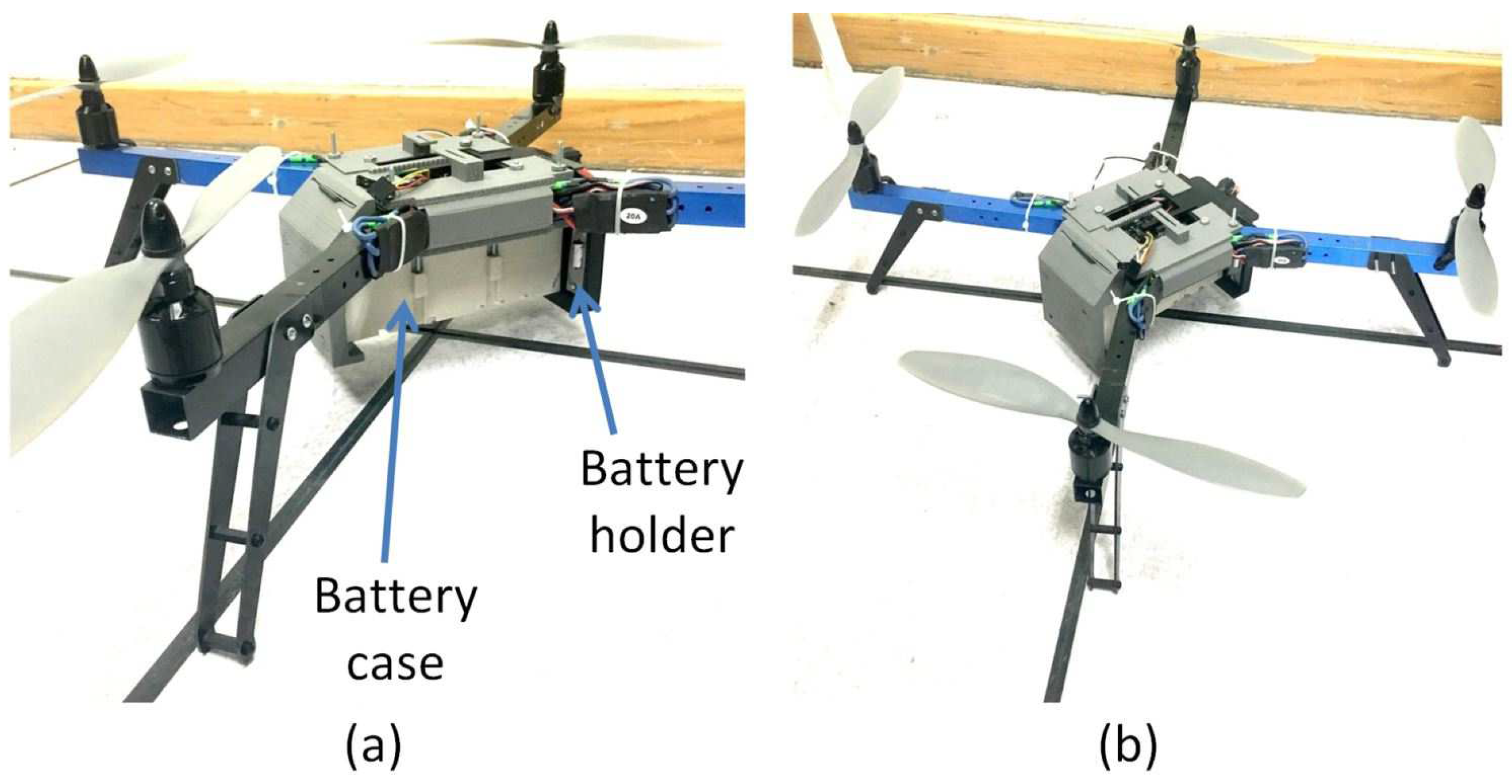
The proposed mechanism for connecting and disconnecting the battery consists of a gripper (see Figure 8) that releases the battery when the quadrotor is on the LS, and its battery has a voltage less than 13.5 V.
The opening or closing of the gripper is performed through a rack–pinion mechanism connected to a servo motor, where the ratio of linear to angular displacement is 1 cm = 2 3 rad (if movement occurs only in one direction). In conclusion, the mechanism generates a total linear displacement of 2 cm for each third of a turn of the servomotor.
Given the complications that gripper deformation can generate, another FEA was conducted with a battery cell (500 g) in an ABS plastic gripper as the chosen material, due to the tensile strength ( 3 × 10 7 N/m 2 ) and elastic modulus ( 2 × 10 9 N/m 2 ) properties. The results obtained through this analysis indicated a maximum stress of 2.589 × 10 5 MPa and a deformation ratio of 1.104 × 10 4 % , in accordance with a material yield stress of 29.6–48 MPa (see Figure 9). Additionally, the resulting shear modulus of 3.189 × 10 8 N/m 2 and maximum displacement of the system in the vertical axis of 0.031 mm demonstrated that there will be no plastic deformation, guaranteeing an absence of deviations in the aforementioned design that could prevent battery exchange.

Battery Case

The battery used was a LiPo-type battery, with 14.8 V nominal voltage and 5200 mAh current. The case was designed based on the specifications listed in Table 1. The connectors shown in Figure 10 are used for power transfer and are responsible for connecting/disconnecting the battery from the charging center. The connectors in Figure 10a are fixed to the charging station, while those in Figure 10b are connected to the battery cases. The case connectors retract in both directions.
The battery case was formed by 3D printing with PLA (polylactic acid, or polylactide) filaments. The proposed design is modular and can be applied to different models; that is, it can be used for batteries with 1–6 cells, as long as their dimensions are smaller than those of the battery selected in this work.

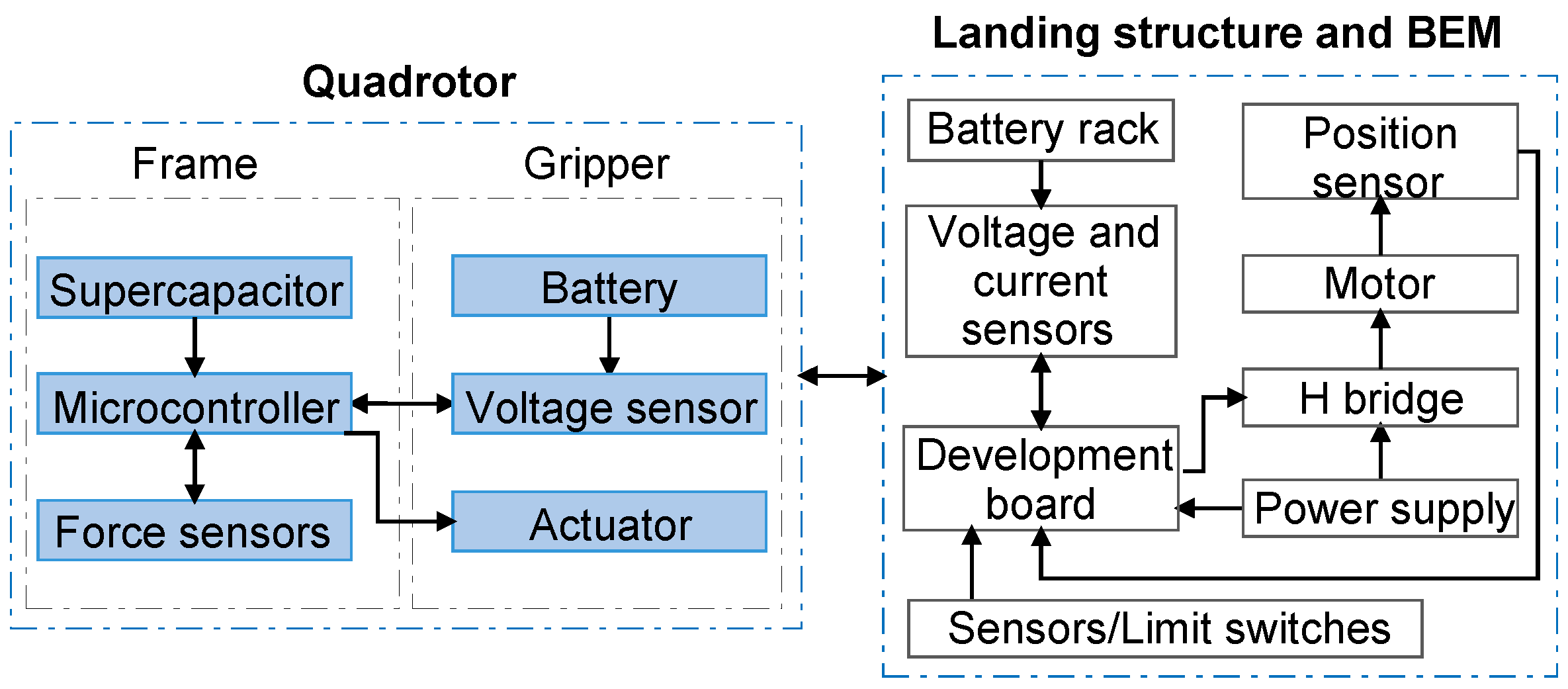
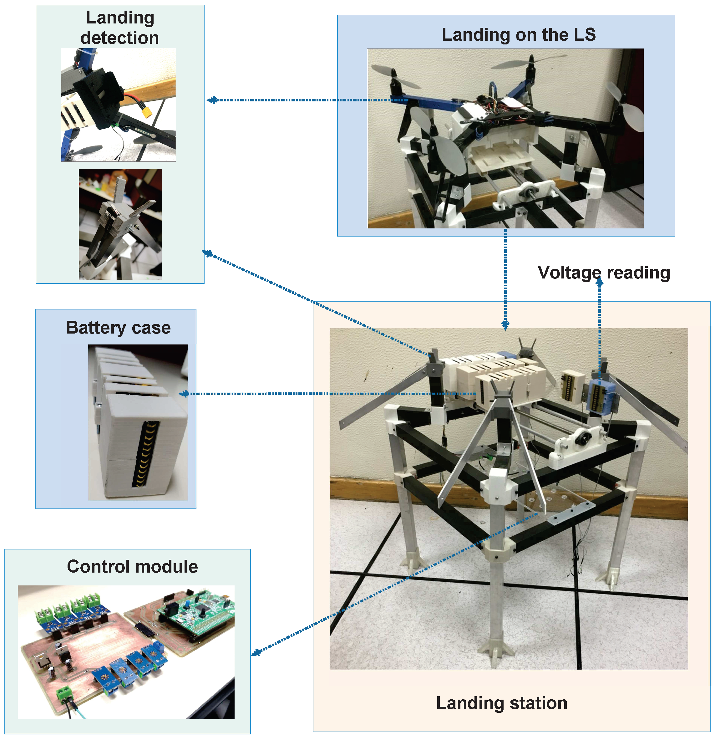
3. Instrumentation and Construction

This section describes the criteria for choosing the electrical and electronic elements of the S-SERQ, as well as their tasks. Figure 11 shows the components used in the S-SERQ and the interactions between them.
As mentioned in the previous section, the S-SERQ does not address the autonomous landing problem. Therefore, sensors and other components are used to enable/disable and control the exchange routine, which is independent of the landing algorithm used. The instrumentation used in the exchange station and quadrotor allows the system to know the status of the batteries and detect when the quadrotor is on the LS, providing the information required to perform the automatic battery exchange.

3.1. Landing Structure and BEM

This section provides the physical results and details regarding the construction and instrumentation of the prototype. The structure consists of CNC-made aluminum parts, 2.54 cm square aluminum tubes (6061 T52 alloy), and 3D-printed parts using polylactide (PLA) filaments. Figure 12 shows the final structure. In addition, the main elements of the S-SERQ are shown.
In S-SERQ, two key modules are used. Voltage, current, and limit switches are located in the first module, while the readings are sent to the second module. The latter module processes the signals obtained by the first module and the encoder. These signals then enter the development board, which generates the PWM and digital signals to be sent to the H-bridge for position control; this module also feeds the motor (see the control module in Figure 12). Thus, the stages are isolated, facilitating the future maintenance or modifications.
The characteristics of the elements of each module are described below:

3.1.1. Module 1

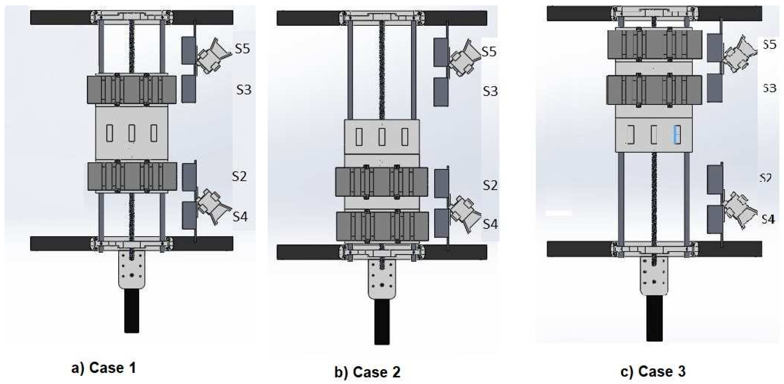
  • Voltage sensors. Four voltage sensors are required to determine which of the batteries has the highest charge and its location. The maximum voltage that the batteries can have is 14.8 V. Thus, the ADCs/5 sensor was chosen, which measures up to 16.5 V with a 3.3 V supply. The selected sensor and development board provide 248.242 B V (4 mV B ) resolution. The resolution obtained for the sensor is small; hence, the obtained measurements are noise sensitive (for this application, ±0.1 V).
    The cell of a LiPo battery delivers approximately 3.9 V at the start of its operation (freshly charged). Subsequently, it begins to decrease until it reaches a constant operating zone (3.7 V), in which it remains for a time t 1 . After t 1 , the voltage drops with a faster time rate ( t 2 ), reaching the point where it delivers 3.3 V, this being the point to avoid in order to maintain cell integrity [5].
    Considering the previous paragraph, and in order to obtain the best possible resolution, the following equation is used to condition the sensor:
    y = V m a x A D C m a x A D C m i n ( x A D C m i n ) + v ,
    where x is the signal of the ADC (B), V m a x is the maximum measurement voltage (15.6 V), A D C m a x is the resolution of the processor (4095 B), A D C m i n corresponds to the ADC obtained with 13.2 V (3.2 KB), y is the conditioned signal (V), and v is the measurement error compensation (V).
  • Current sensors. Four current sensors are used to monitor the current during the battery charging process. The rationale for using four sensors is that LiPo batteries with more than 3.7 V are the result of connecting two or more cells in series. Therefore, the current in each of the cells is the same.
    The sensors used were the ACS712ELC-20 model, which allow for measuring up to 20 A and have a sensitivity of 100 mV/A. The noise present in these sensors can cause problems during the implementation of a charging control algorithm. Thus, the following moving average filter was used [36]:
    y [ n ] = 1 N x [ n ] + i = 1 n 1 x [ n i ] + x [ n N + 1 ] ,
    where y [ n ] is the output and x [ n ] is the input applied to the filter. If the value of N is large enough, the output will have a better response. Its performance is affected by a time delay in reading, which is equal to ( N 1 ) / 2 units of time.
    For this work, a 25-sample time window is used, which updates each sampling period (0.005 s), placing the new reading at the first position of a 25-value vector and discarding the value located at the last position, thus obtaining a signal with oscillations of ±0.003 A and a delay of 0.125 s. The above represents a good result, considering that the original signal has oscillations of ±0.3 A.
    After the filtering action, the signal is conditioned by the following equation:
    y c = x c A D C m i n c s + a ,
    where x c is the input signal (B), A D C m i n c corresponds to the value of the ADC when 0 A is measured (3.256 KB), s indicates the sensitivity of the sensor 129.3 B A , a is the measurement compensation (A), and y c is the conditioned signal (A).
    A D C m i n c and s were obtained experimentally using a variable load of 0 to 3 A, with increments of 100 mA at each reading. The data were entered as a vector to the polyfit function in MATLAB, obtaining a first-degree polynomial describing the behavior of the ADC with respect to the current reading ( i R ). The polynomial obtained is as follows:
    A D C = s ( i R ) + A D C m i n c = 129.3 x + 3256.1 .

3.1.2. Module 2

  • Development board. For signal processing, calculation, and sending of the control signal to the system using the pulse-width modulation (PWM) technique, the STM32F407G-DISC development board was used, programmed using the MATLAB-Simulink software [37]. The card has a 32-bit ARM processor, 12-bit resolution for the ADC, and 16-bit resolution for the PWM. Finally, the sampling period was 0.005 s.
  • Motor. Based on Table 1, the desired linear velocity, v, is
    v = 0.1 m 10 s = 0.01 m s .
    The force F d required to move the batteries is:
    F d = 0.498 kg ( 3 ) 9.81 m s 2 = 14.656 N 20 N .
    The previous calculation was made considering three batteries. Thus, considering the presence of friction between the batteries and the rails, a design force of 20 N was proposed. The power required P for the motor is [38]
    P = F d v = 0.2 W 2.682 × 10 4 hp ,
    and the required torque T is obtained by
    P = T ω ,
    where ω represents the angular velocity of the motor, which, according to the characteristics of the screw and nuts selected, is 1.234 rps. Therefore,
    ω = 7.7534 rad s T = 0.0257 Nm .
    With the obtained data, a Pololu model 37D 131:1 DC motor was selected, which generates a torque of 0.883 Nm when supplied at 6 V and 2.5 A. Considering the average battery charging time in a drone, the motor must run for 10 s every 15 min, which does not significantly affect the power consumption of the station.
  • Position sensor. An incremental optical encoder (encoder) with a resolution of 64 pulses per revolution was selected for the motor shaft. However, the motor has a gearbox with a ratio of 131:1. Therefore, the combination of the encoder and the motor resulted in 8284 pulses for each revolution at the motor output.
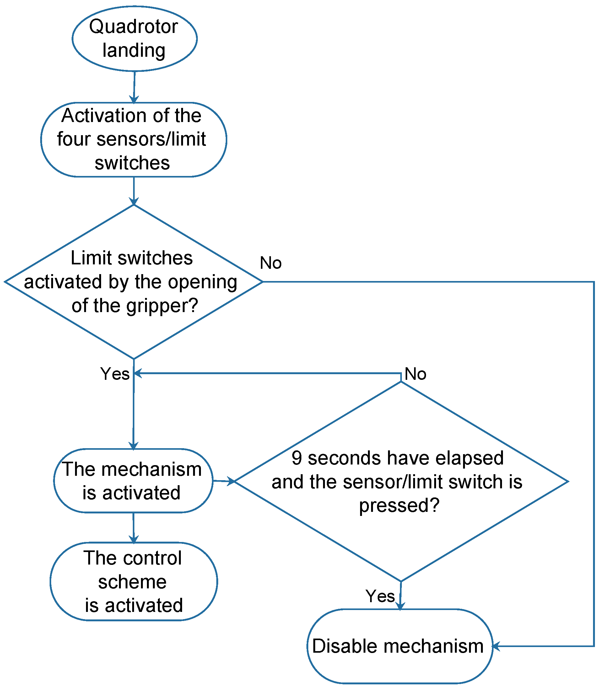
  • Sensors/limit switches. These have two objectives: Activation and calibration of the mechanism. The first requires five sensors: four placed in the support points of the structure and one placed in such a way that it is pressed when releasing the battery. When the five sensors are pressed, the mechanism begins the exchange process.
    With respect to the second target, the sixth sensor is placed at the opposite end of the motor, which is used to calibrate the mechanism when the power supply is restarted.
  • H bridge. The selected H bridge is a VNH2SP30 model, which provides a supply voltage to the motor between 5.5 and 16 V and supports a maximum current of 30 A.

3.2. Battery Release/Clamp Mechanism

The gripper was made from PLA using a 3D printer. It should be mentioned that the clamp does not allow the battery to fall during flight maneuvers, as it possesses a clamping mechanism that limits the movement of the battery case (see Figure 13).
The components used to release/clamp the quadrotor battery are described in the following:
  • Microcontroller. A peripheral interface controller (PIC) PIC16F887 was selected to open and close the gripper, which is powered at 5 V and has a 10-bit resolution for analog–digital conversion. The PIC performs the acquisition of signals from the voltage and force sensors.
  • Supercapacitor. Considering that the quadrotor runs out of power during the battery exchange, an element is required to supply power to the electronic speed controllers (ESCs), PIC, and the inertial navigation system (SNI). Based on the above, an A V X supercapacitor model SCMR14C474MRBA0 of 0.47 F was selected, which is capable of supplying 5 V for 14 s, avoiding the loss of configuration of the entire logical part of the UAV.
  • Actuator. The opening and closing of the gripper is conducted using a servomotor coupled to the sprocket of the mechanism; in this case, a SG-90 model was used, which has a torque of 1.8 Kgf·cm and is controlled by a P W M signal. With a PWM of 0, the gripper remains closed; if the PWM has a period of 2 ms, the mechanism remains open.
  • Voltage sensor. An A D C s / 5 sensor (see Section 3.1) is used to monitor the battery voltage in the quadrotor, in order to indicate when it should be changed.
  • Force sensors. These are placed at the contact points of the quadrotor legs with the landing frame. Four sensors are used and, by means of a voltage divider, a signal between 0 and 5 V is obtained. The sensors used are MF01-N-221-A01 models, with an operating range of 0–1000 g. Considering that the weight of the quadrotor is 2.5 kg, each sensor must support 625 g. Therefore, when the vehicle is on the LS, the sensors deliver a voltage greater than 2.5 V.
The instrumentation described determines the conditions under which the battery must be released and replaced. These conditions are given by the voltage sensor and the force sensors.

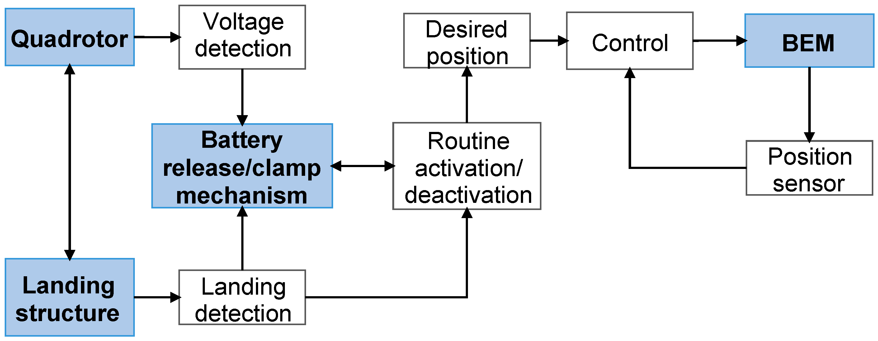
4. Control and Operation Scheme

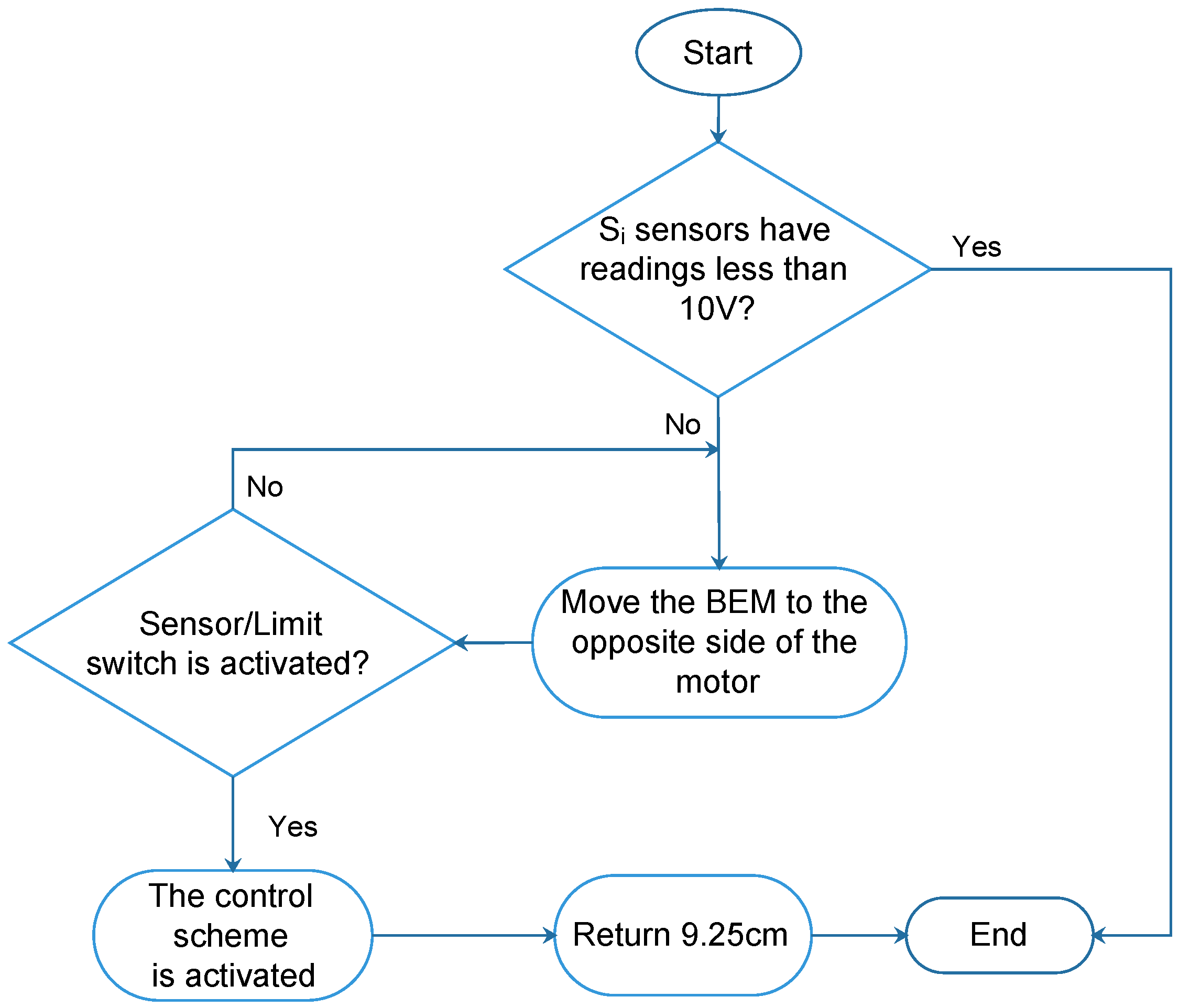
4.1. BEM Operation Logic

The operation of the station is based on the following algorithm (see Figure 14). When the quadrotor lands on the station, four limit switches are pressed (see landing detection in Figure 12), thus activating the exchange routine.
To start the exchange process, a comparison of the voltage sensor readings is made, determining the location of the battery with the most charge (i.e., the position control reference corresponds to the location of the battery with the most charge).

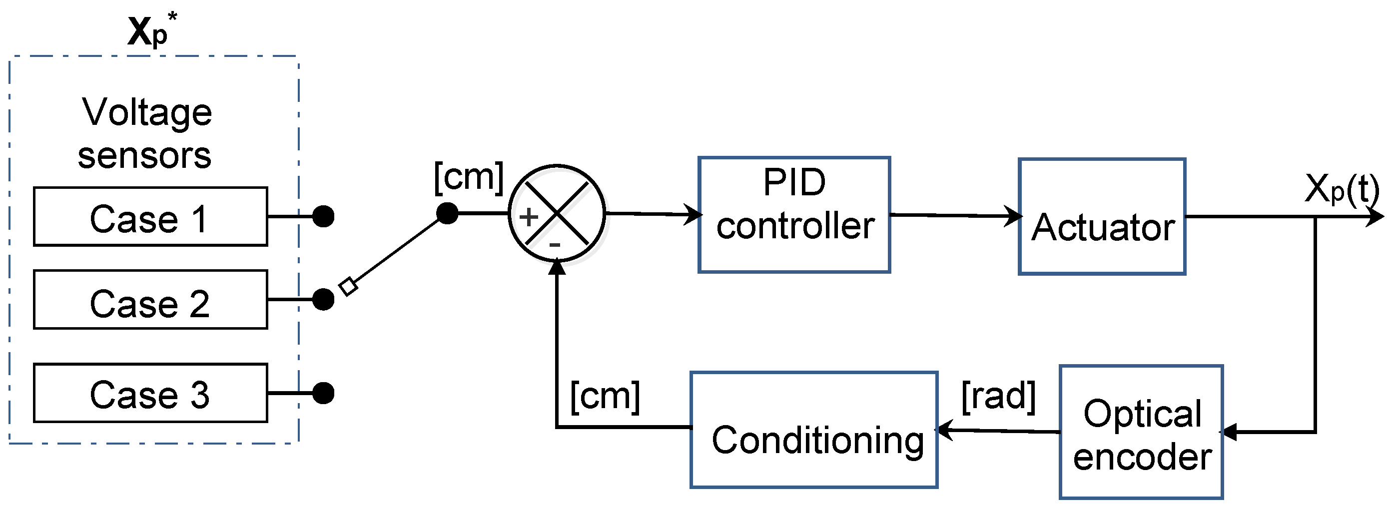
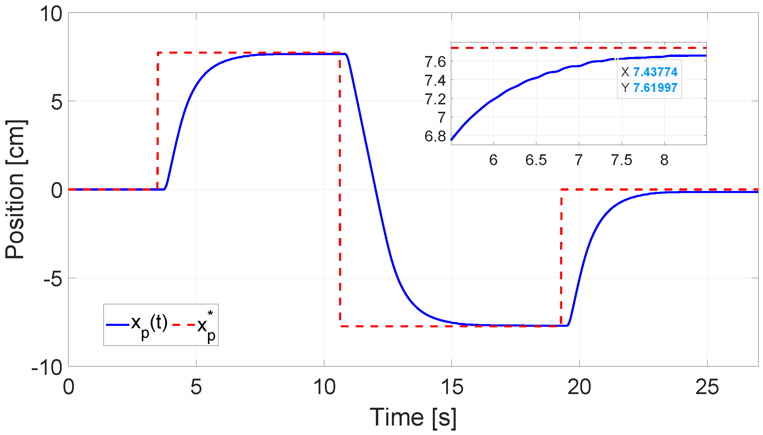
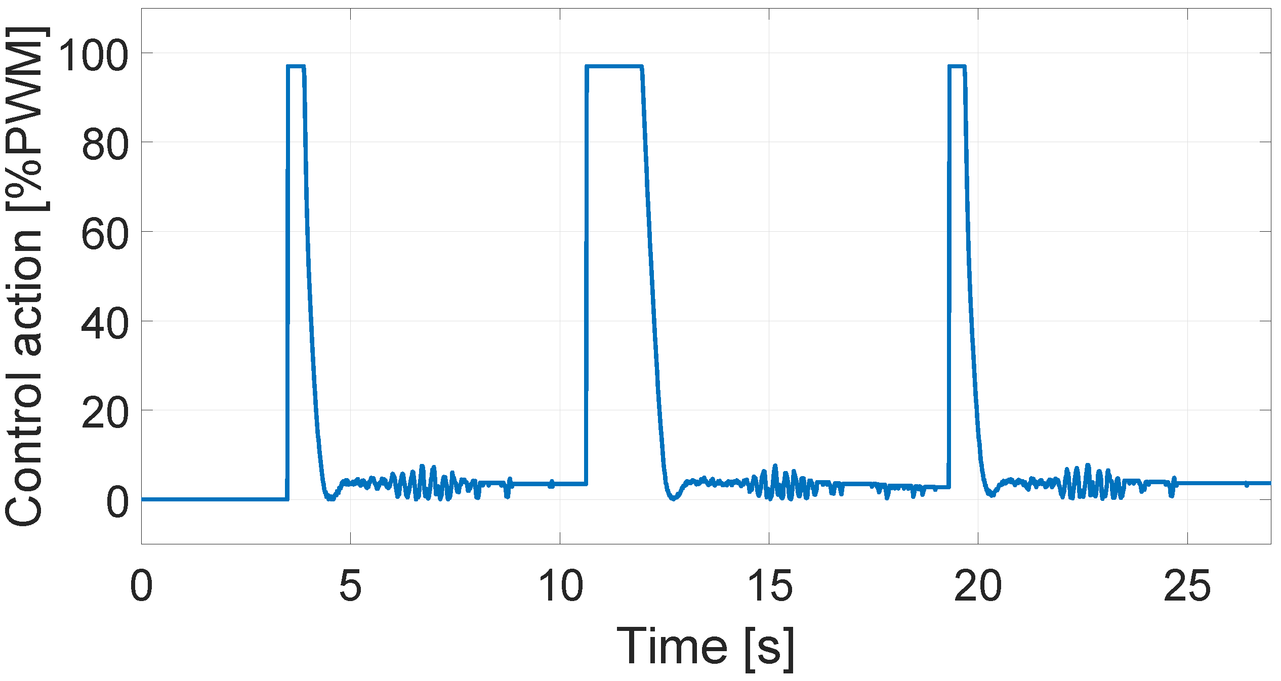
4.1.1. Position Control in the BEM

The position control implemented is of the proportional integral derivative (PID) type, which has a variable desired value (setpoint) that depends on the location of the most-charged battery. The implemented routine includes three possible cases, as shown in Figure 15. The labels S i correspond to the voltage sensors, which operate continuously in order to comply with the following routine:
C a s e 1 ( S 2 & S 3 > 13.5 V ) S 2 > S 3 , x p * = 7.74 cm ; S 3 > S 2 , x p * = 7.74 cm .
C a s e 2 ( S 2 & S 4 > 13.5 V ) S 2 > S 4 , x p * = 0 cm ; S 4 > S 2 , x p * = 7.74 cm .
C a s e 3 ( S 5 & S 3 > 13.5 V ) S 3 > S 5 , x p * = 0 cm ; S 5 > S 3 , x p * = 7.74 cm ,
where x p * is the desired position value. The angular position of the motor is measured by means of an encoder, and each revolution corresponds to 0.81 cm displacement in the BEM.
After identifying the most-charged battery, the selective control sends the reference value to the position control, including the distance (in centimeters) that the platform must travel such that the battery with the most charge is in a position to be taken by the quadrotor (see Figure 16).
Due to the lack of a mathematical model for the motor, the tuning of the controller was experimentally carried out using the sustained oscillations method (see Figure 17) of Ziegler and Nichols [39].
The critical gain ( G c ) obtained was 200, resulting in 5.618 cycles per second w c = 35.184 rad s , equivalent to a critical period ( p c ) of 0.178 s. Therefore, using the Ziegler–Nichols procedure for a PID controller [40], the tuning parameters were k c = G c 1.7 = 117.647 , T i = p c 2 = 0.089 , and T d = p c 8 = 0.022 . Finally, the PID controller gains were obtained by evaluating the parameters k c , T i , and T d in the following equation [41]:
u ( t ) = k p e ( t ) + k i 0 t e ( τ ) d τ + k d d d t e ( t ) ,
where k p = k c , k i = k p T i = 1321.876 , k d = k p T d = 2.588 , and the error e ( t ) is defined as the desired value x p * minus the measured position value x p . After some tests, the gains used were k p = 120 , K i = 1047 , and K d = 3.62 . Figure 18 depicts the response of the BEM once the control scheme described in Figure 14 is activated. The graph shows three cases (setpoints), the second being the maximum displacement required to place the battery further away in the center of the BEM. It is important to note that the battery change in case 2 can be completed in 6 s, while in cases 1 and 2, it requires 4 s. It should be highlighted that, in all cases, no oscillations or overshoots were observed in the position.
Figure 19 shows the control action exerted on the BEM once the quadrotor has landed on the LS and the control scheme has been activated (see Figure 14). Small oscillations can be observed, which do not affect the position of the mechanism. This is demonstrated by approaching the control action in the time interval of 5.5–8.5 s shown in Figure 20. Once the steady-state (setpoint) has been reached, the control action is bounded between 0 and 8 % P W M , and has a frequency of approximately 25 rad/s. It should be noted that a PWM percentage larger than 6 % is required to move the motor. Furthermore, due to gear reduction, the peaks between 6 and 8 % cannot be perceived in the final position of the mechanism.

4.1.2. Calibration Routine

Considering the operating conditions, it is possible that the conditions of cases 1, 2, and 3 described above are not satisfied by the mechanism. This may be the result of a loss of supply during operation or changes in the friction of the mechanism. In this case, the routine depicted in Figure 21 is used.
The calibration process consists of moving the mechanism to the end of the rail. Later, it returns 9.25 cm; this being the distance that places the center of the mechanism at the point where the discharged battery will arrive.

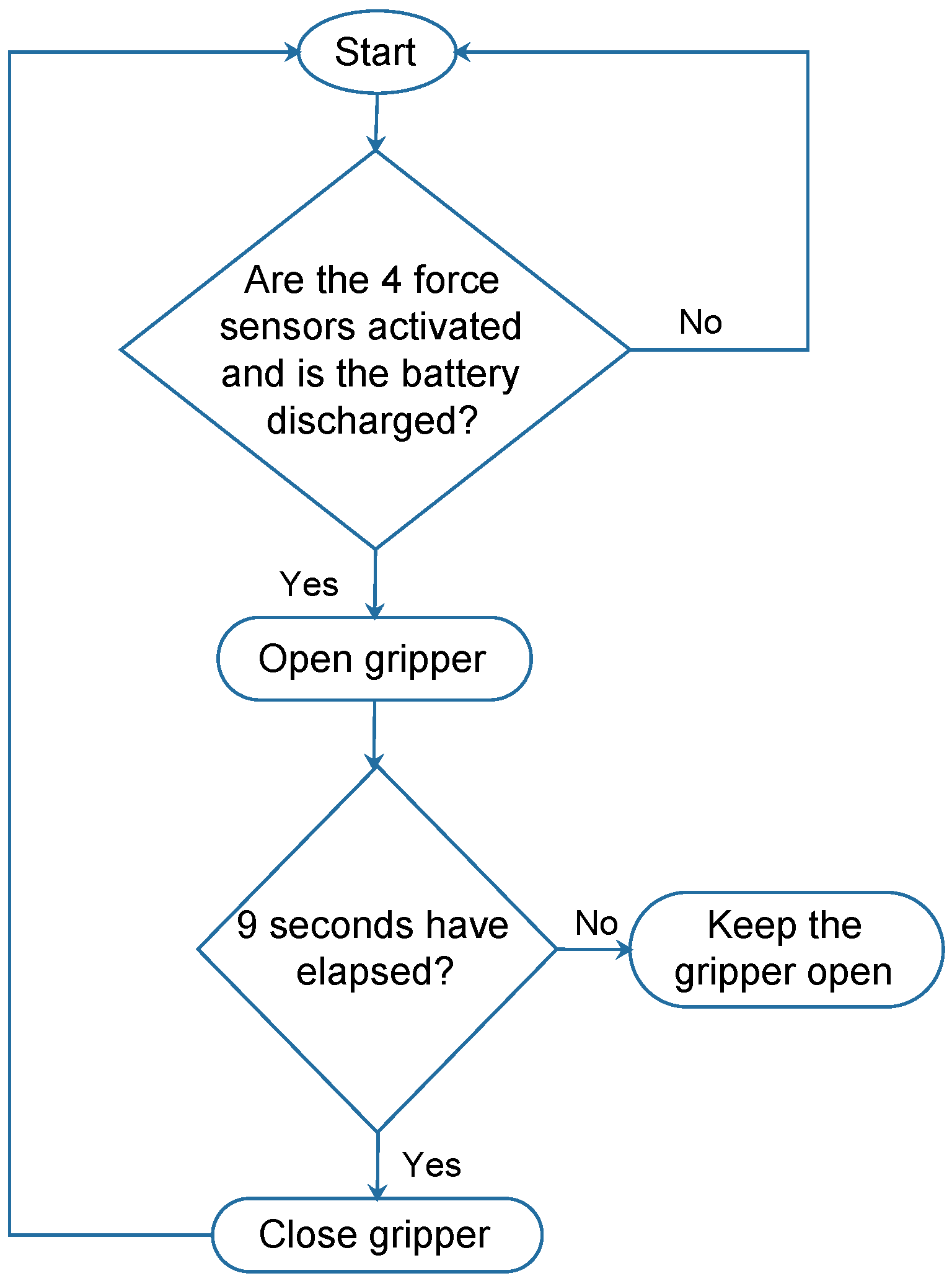
4.2. Battery Release/Clamp Mechanism Operation

If the voltage sensor detects a value less than 13.5 V, a low voltage alarm is activated. However, if the force sensors do not detect that the vehicle is on the BEM, the gripper cannot be opened. To open it, the four force sensors must detect a weight greater than 500 g and the battery voltage must be less than 13.5 V. If these conditions are satisfied, the gripper opens for 9 s for battery release; then, it closes, thus placing the new battery (see Figure 22).

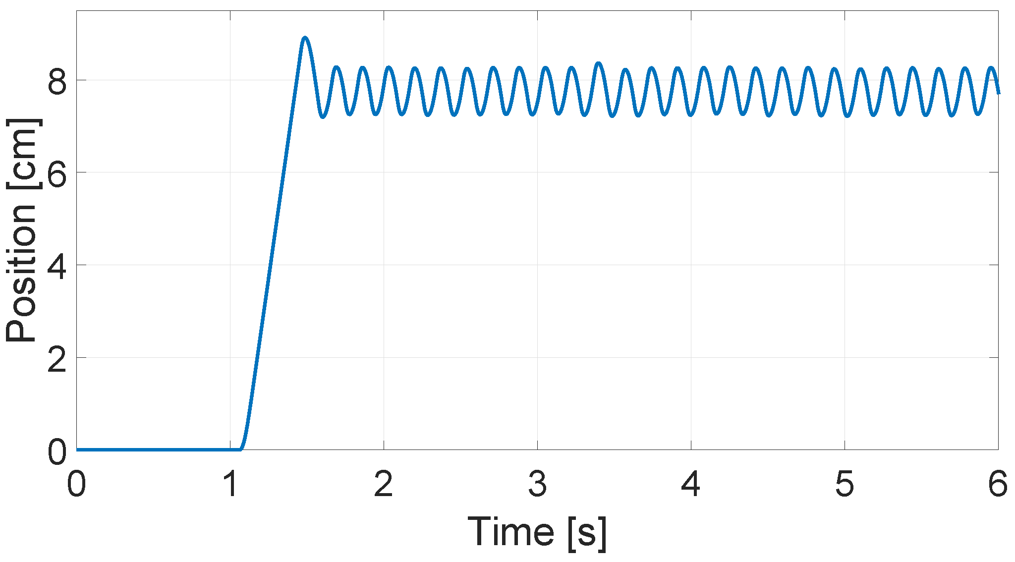
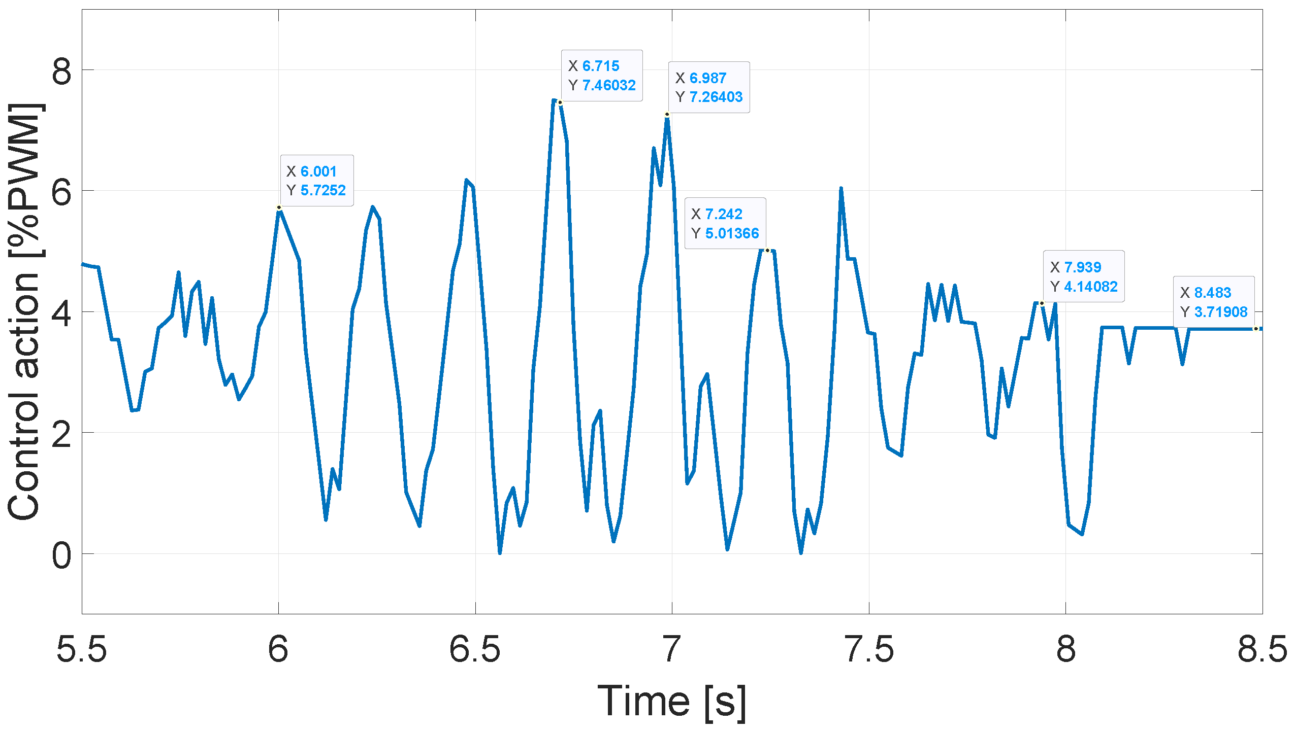
5. Results and Discussion

The S-SERQ proposed in this work facilitates the landing of a quadrotor on the LS, does not require extremely precise control in the angle ψ (i.e., variations less than ±0.2 rad are acceptable), and reduces the effects generated by the air during landing. It should be noted that the proposed mechanism only uses a motor to change the battery. The proposed instrumentation and control scheme allow the S-SERQ to work with two batteries in charging mode. Furthermore, the selected instrumentation allows for the determination of the location of the battery with the most charge, through a supervision routine. On the other hand, the current sensors monitor the state of charge of the batteries, with the implementation of a charger remaining as future work.
The control scheme used is selective; that is, the reference is determined as the position of the most-charged battery. It should be noted that the position of each battery corresponds to the locations of the voltage and current sensors.
The S-SERQ design and instrumentation proposal was validated by PID position control, programmed through the MATLAB Simulink Waijung Blockset, despite the chattering effect that usually appears in various control laws (see [42]). The 131:1 reduction of the motor, the displacement ratio of 0.81 cm/rev of the mechanism, and the need to have a control action greater than 6% to move the motor served to minimize the impact of vibrations (range [0–8%PWM] and frequency [25 rad/s]) in the final position of the BEM. It should be noted that, in the case that a faster battery exchange is required, the controller gains, or even the motor, would have to be changed. This could increase the presence of chattering in the control signals [43], requiring the development of control schemes that minimize this effect [42,44].
In relation to the gripper that holds and releases the battery, this action is achieved through a servomotor that determines the opening time by means of a set of sensors placed on the structure of the quadrotor and the gripper, which can achieve battery exchange in less than 10 s.
Regarding the number of batteries used, it is possible to increase the number of batteries; for this, only the length of BEM needs to be increased and more sensors need to be integrated. However, the control scheme would not change. Thus, the proposed instrumentation and control algorithm can serve as the basis for the design of a new S-SERQ that can re-supply several quadrotors.
It should be noted that the components used in the S-SERQ are low cost and easily accessible. Therefore, this proposal can be considered attractive for its use in different applications that require long, routine flights.

6. Conclusions

The concept of the service station (including the gripper) presented in this work presents scaling properties that provide the opportunity for its implementation with in other quadrotor models (after some modifications; mainly scaling), as long as the battery can be placed on the bottom of the UAV. This is possible thanks to the design of the battery case and the type of connectors used, which allow for the use of batteries from 1 to 6 cells with maximum dimensions of 32 × 50 × 160 mm. It is important to mention that, at present, a wide variety of quadrotor designs are available on the market; therefore, it is very likely that the proposed service station must be adapted to a specific model. This is one of the key challenges to overcome, as most works related to this topic have made use of custom UAVs to develop and demonstrate their proposed solution in a practical way [45].
As mentioned in the introduction, this paper aimed to detail a methodology for the design, construction, and instrumentation of S-SERQ. Therefore, the problem of landing on the station was not addressed. Thus, as future work, we intend to address the problem of autonomous landing on the S-SERQ, which may be achieved using control techniques and artificial vision, such as those described in [9,46,47]. Some works reporting the integration of battery exchange systems and automatic landings include [48,49]; however, these studies do not describe the design methodology used for the construction and instrumentation of their stations, this being the main contribution of our work.
It is important to mention that, at present, charging platforms are better suited to low-coverage UAVs, while exchange stations allow for high coverage with fewer UAVs [23]. This is due to the complicated technologies related to the alternative charging options; for example, fuel cells present problems when there is a large variation in energy demand, which can lead to problems related to a lack of fuel, thus affecting their useful life, reliability, and efficiency [50].
In future works, we intend to attempt to incorporate solar energy collection systems, as well as the use of sensors that allow for the incorporation of communication stages between the quadrotor and the LS, providing that information to the quadrotor control scheme, in addition to incorporating a greater number of batteries (to minimize downtime) and building a case to protect the LS from climatic factors (e.g., humidity and dust). Finally, a safety and emergency stop system must be implemented that guarantees the integrity of the environment, people and equipment in the presence of unsafe operating conditions of the S-SERQ.

Author Contributions

Conceptualization, Y.L.-H., O.G.-F. and A.L.-J.; methodology, N.L.-C. and A.L.-J.; software, I.M.d.l.C.; validation, Y.L.-H., I.M.d.l.C., O.G.-F. and A.L.-J.; writing—original draft preparation, Y.L.-H. and O.G.-F.; writing—review and editing, N.L.-C. and A.L.-J.; visualization, I.M.d.l.C. and N.L.-C.; funding acquisition, Y.L.-H., O.G.-F., N.L.-C. and A.L.-J. All authors have read and agreed to the published version of the manuscript.

Funding

This research was funded by Secretaria de Investigación y Posgrado-IPN grants numbers 20232388, 20231585, and 20231632.

Institutional Review Board Statement

Not applicable.

Informed Consent Statement

Not applicable.

Data Availability Statement

Not applicable.

Acknowledgments

Ismael Martínez de la Cruz thanks the support from the CONACYT.

Conflicts of Interest

The authors declare no conflict of interest.

References

  1. Chamola, V.; Kotesh, P.; Agarwal, A.; Gupta, N.; Guizani, M. A comprehensive review of unmanned aerial vehicle attacks and neutralization techniques. Ad Hoc Netw. 2021, 111, 102324. [Google Scholar] [CrossRef] [PubMed]
  2. Ragel, R.; Maza, I.; Caballero, F.; Ollero, A. Plataforma para el Aterrizaje y el Intercambio de Baterıas Automático para un UAV de tipo VTOL. In Proceedings of the Actas de las XXXVI Jornadas de Automática, Bilbao, Spain, 2–4 September 2015; pp. 338–344. [Google Scholar]
  3. Fujii, K.; Higuchi, K.; Rekimoto, J. Endless flyer: A continuous flying drone with automatic battery replacement. In Proceedings of the 2013 IEEE 10th International Conference on Ubiquitous Intelligence and Computing and 2013 IEEE 10th International Conference on Autonomic and Trusted Computing, Vietri sul Mare, Italy, 18–21 December 2013; pp. 216–223. [Google Scholar]
  4. Lozano-Hernández, Y.; Gutiérrez Frías, O.; Lozada-Castillo, N.; Luviano-Juárez, A. Control algorithm for taking off and landing manoeuvres of quadrotors in open navigation environments. Int. J. Control Autom. Syst. 2019, 17, 2331–2342. [Google Scholar] [CrossRef]
  5. Lozano, Y.; Gutiérrez, O. Design and control of a four-rotary-wing aircraft. IEEE Lat. Am. Trans. 2016, 14, 4433–4438. [Google Scholar] [CrossRef]
  6. Bauranov, A.; Rakas, J. Designing airspace for urban air mobility: A review of concepts and approaches. Prog. Aerosp. Sci. 2021, 125, 100726. [Google Scholar] [CrossRef]
  7. Xu, Y.; Dan, Y.; Raymond, M.T. Production of Solar-powered Quad-copter for Agricultural Field Spraying. J. Phys. Conf. Ser. 2022, 2383, 012036. [Google Scholar] [CrossRef]
  8. Silva, M.; Mourato, A.; Marques, G.; Sargento, S.; Reis, A. A Platform for Autonomous Swarms of UAVs. In Proceedings of the 2022 IEEE Symposium on Computers and Communications (ISCC), Rhodes, Greece, 30 June–3 July 2022; pp. 1–6. [Google Scholar]
  9. Boukoberine, M.N.; Zhou, Z.; Benbouzid, M. A critical review on unmanned aerial vehicles power supply and energy management: Solutions, strategies, and prospects. Appl. Energy 2019, 255, 113823. [Google Scholar] [CrossRef]
  10. Moon, G.; Kim, Y. Optimum flight path design passing through waypoints for autonomous flight control system. In Proceedings of the AIAA Guidance, Navigation, and Control Conference and Exhibit, Austion, TX, USA, 11–14 August 2003; p. 5334. [Google Scholar]
  11. Mohsan, S.A.H.; Othman, N.Q.H.; Khan, M.A.; Amjad, H.; Żywiołek, J. A comprehensive review of micro UAV charging techniques. Micromachines 2022, 13, 977. [Google Scholar] [CrossRef]
  12. Michini, B.; Toksoz, T.; Redding, J.; Michini, M.; How, J.; Vavrina, M.; Vian, J. Automated battery swap and recharge to enable persistent UAV missions. In Infotech@Aerospace 2011; American Institute of Aeronautics and Astronautics: Reston, VA, USA, 2011; p. 1405. [Google Scholar]
  13. Mulgaonkar, Y. Small, Safe Quadrotors for Autonomous Flight. Ph.D. Thesis, University of Pennsylvania, Philadelphia, PA, USA, 2019. [Google Scholar]
  14. Lee, D.; Zhou, J.; Lin, W.T. Autonomous battery swapping system for quadcopter. In Proceedings of the 2015 International Conference on Unmanned Aircraft Systems (ICUAS), Denver, CO, USA, 9–12 June 2015; pp. 118–124. [Google Scholar]
  15. Swieringa, K.A.; Hanson, C.B.; Richardson, J.R.; White, J.D.; Hasan, Z.; Qian, E.; Girard, A. Autonomous battery swapping system for small-scale helicopters. In Proceedings of the 2010 IEEE international conference on robotics and automation, Anchorage, AK, USA, 3–7 May 2010; pp. 3335–3340. [Google Scholar]
  16. Zhou, F.; Wu, Y.; Hu, R.Q.; Qian, Y. Computation rate maximization in UAV-enabled wireless-powered mobile-edge computing systems. IEEE J. Sel. Areas Commun. 2018, 36, 1927–1941. [Google Scholar] [CrossRef] [Green Version]
  17. Dunbar, S.; Wenzl, F.; Hack, C.; Hafeza, R.; Esfeer, H.; Defay, F.; Prothin, S.; Bajon, D.; Popovic, Z. Wireless far-field charging of a micro-UAV. In Proceedings of the 2015 IEEE Wireless Power Transfer Conference (WPTC), Boulder, CO, USA, 13–15 May 2015; pp. 1–4. [Google Scholar]
  18. Alhassan, A.B.; Zhang, X.; Shen, H.; Xu, H. Power transmission line inspection robots: A review, trends and challenges for future research. Int. J. Electr. Power Energy Syst. 2020, 118, 105862. [Google Scholar] [CrossRef]
  19. Mohsan, S.A.H.; Khan, M.A.; Noor, F.; Ullah, I.; Alsharif, M.H. Towards the unmanned aerial vehicles (UAVs): A comprehensive review. Drones 2022, 6, 147. [Google Scholar] [CrossRef]
  20. Chittoor, P.K.; Chokkalingam, B.; Mihet-Popa, L. A review on UAV wireless charging: Fundamentals, applications, charging techniques and standards. IEEE Access 2021, 9, 69235–69266. [Google Scholar] [CrossRef]
  21. Pan, Z.; An, L.; Wen, C. Recent advances in fuel cells based propulsion systems for unmanned aerial vehicles. Appl. Energy 2019, 240, 473–485. [Google Scholar] [CrossRef]
  22. Hwang, J.J.; Kuo, J.K.; Wu, W.; Chang, W.R.; Lin, C.H.; Wang, S.E. Lifecycle performance assessment of fuel cell/battery electric vehicles. Int. J. Hydrogen Energy 2013, 38, 3433–3446. [Google Scholar] [CrossRef]
  23. Kemper, F.P.; Suzuki, K.A.; Morrison, J.R. UAV consumable replenishment: Design concepts for automated service stations. J. Intell. Robot. Syst. 2011, 61, 369–397. [Google Scholar] [CrossRef]
  24. Ure, N.K.; Toksoz, T.; Chowdhary, G.; Redding, J.; How, J.; Vavrina, M.; Vian, J. Experimental demonstration of multi-agent learning and planning under uncertainty for persistent missions with automated battery management. In Proceedings of the AIAA Guidance, Navigation, and Control Conference, Minneapolis, MN, USA, 13–16 August 2012; p. 4622. [Google Scholar]
  25. Malyuta, D.; Brommer, C.; Hentzen, D.; Stastny, T.; Siegwart, R.; Brockers, R. Long-duration fully autonomous operation of rotorcraft unmanned aerial systems for remote-sensing data acquisition. J. Field Robot. 2020, 37, 137–157. [Google Scholar] [CrossRef] [Green Version]
  26. Grlj, C.G.; Krznar, N.; Pranjić, M. A Decade of UAV Docking Stations: A Brief Overview of Mobile and Fixed Landing Platforms. Drones 2022, 6, 17. [Google Scholar]
  27. Smith, C.A. Automated Continuous Process Control; John Wiley & Sons: Hoboken, NJ, USA, 2003. [Google Scholar]
  28. Demirhan, M.; Premachandra, C. Development of an automated camera-based drone landing system. IEEE Access 2020, 8, 202111–202121. [Google Scholar] [CrossRef]
  29. Xuan-Mung, N.; Hong, S.K.; Nguyen, N.P.; Le, T.L. Autonomous quadcopter precision landing onto a heaving platform: New method and experiment. IEEE Access 2020, 8, 167192–167202. [Google Scholar] [CrossRef]
  30. Jain, K.P.; Mueller, M.W. Flying batteries: In-flight battery switching to increase multirotor flight time. In Proceedings of the 2020 IEEE International Conference on Robotics and Automation (ICRA), Paris, France, 31 May–31 August 2020; pp. 3510–3516. [Google Scholar]
  31. Galimov, M.; Fedorenko, R.; Klimchik, A. UAV Positioning Mechanisms in Landing Stations: Classification and Engineering Design Review. Sensors 2020, 20, 3648. [Google Scholar] [CrossRef]
  32. Verstraete, D.; MacNeill, R. The Effects of Blockage on the Performance of Small Propellers. In Proceedings of the 20th Australasian Fluid Mechanics Conference, Perth, Australia, 5–8 December 2016. [Google Scholar]
  33. Papayanopoulos, J.F. Autonomous UAV Precision Item Pickup. Ph.D. Thesis, Georgia Institute of Technology, Atlanta, GA, USA, 2017. [Google Scholar]
  34. Bock, S. New open-source ANSYS-SolidWorks-FLAC3D geometry conversion programs. J. Sustain. Min. 2015, 14, 124–132. [Google Scholar] [CrossRef] [Green Version]
  35. Lubliner, J. Plasticity Theory; Courier Corporation: Chelmsford, MA, USA, 2008. [Google Scholar]
  36. Kamen, E.W.; Heck, B.S. Fundamentals of Signals and Systems Using the Web and Matlab; Pearson New International: London, UK, 2014. [Google Scholar]
  37. Ayachi Amor, Y.; Kheldoun, A.; Metidji, B.; Hamoudi, F.; Merazka, A.; Lazoueche, Y. Implementation of modified SVPWM for three-level inverter using STM32F4. In Proceedings of the 2018 International Conference on Electrical Sciences and Technologies in Maghreb (CISTEM), Algiers, Algeria, 28–31 October 2018; pp. 1–6. [Google Scholar]
  38. Hetmańczyk, J.; Stenzel, T.; Grzesik, B. Selected aspects of design and modelling of linear actuator based on PM BLDC motor. Przegląd Elektrotechniczny 2015, 6. [Google Scholar] [CrossRef] [Green Version]
  39. Ahmed, H.; Singh, G.; Bhardwaj, V.; Saurav, S.; Agarwal, S. Controlling of DC Motor using Fuzzy logic controller. In Proceedings of the Conference on Advances in Communication and Control Systems, Khartoum, Sudan, 16–18 January 2013; pp. 666–670. [Google Scholar]
  40. Elsrogy, W.M.; Fkirin, M.; Moustafa Hassan, M.A. Speed control of DC motor using PID controller based on artificial intelligence techniques. In Proceedings of the 2013 International Conference on Control, Decision and Information Technologies (CoDIT), Hammamet, Tunisia, 6–8 May 2013; pp. 196–201. [Google Scholar]
  41. Montiel, O.; Sepulveda, R.; Melin, P.; Castillo, O.; Porta, M.; Meza, I.M. Performance of a simple tuned fuzzy controller and a PID controller on a DC motor. In Proceedings of the 2007 IEEE Symposium on Foundations of Computational Intelligence, Honolulu, HI, USA, 1–5 April 2007; pp. 531–537. [Google Scholar]
  42. Abro, G.E.M.; Asirvadam, V.S.; Zulkifli, S. Single-Input Fuzzy-Sliding Mode Control for an Underactuated Quadrotor Craft. In Proceedings of the 2020 IEEE 2nd International Conference on Artificial Intelligence in Engineering and Technology (IICAIET), Kinabalu, Malaysia, 26–27 September 2020; pp. 1–6. [Google Scholar]
  43. Lee, S.J.; Jang, I.; Kim, H.J. Fail-Safe Flight of a Fully-Actuated Quadrotor in a Single Motor Failure. IEEE Robot. Autom. Lett. 2020, 5, 6403–6410. [Google Scholar] [CrossRef]
  44. Manouchehri, P.; Ghasemi, R.; Toloei, A. Distributed Fuzzy Adaptive Sliding Mode Formation for Nonlinear Multi-quadrotor Systems. Int. J. Eng. 2020, 33, 798–804. [Google Scholar]
  45. Grobler, R. Automated recharging and vision-based improved localisation for a quadrotor UAV. Ph.D. Thesis, Stellenbosch University, Stellenbosch, South Africa, 2021. [Google Scholar]
  46. Rajabi, M.S.; Beigi, P.; Aghakhani, S. Drone Delivery Systems and Energy Management: A Review and Future Trends. arXiv 2022, arXiv:2206.10765. [Google Scholar]
  47. De Silva, S.C.; Phlernjai, M.; Rianmora, S.; Ratsamee, P. Inverted Docking Station: A Conceptual Design for a Battery-Swapping Platform for Quadrotor UAVs. Drones 2022, 6, 56. [Google Scholar] [CrossRef]
  48. Bongermino, E.; Mastrorocco, F.; Tomaselli, M.; Monopoli, V.G.; Naso, D. Model and energy management system for a parallel hybrid electric unmanned aerial vehicle. In Proceedings of the 2017 IEEE 26th International Symposium on Industrial Electronics (ISIE), Edinburgh, UK, 19–21 June 2017; pp. 1868–1873. [Google Scholar]
  49. Glassock, R.; Hung, J.; Gonzalez, L.; Walker, R. Multimodal hybrid powerplant for unmanned aerial systems (UAS) Robotics. In Proceedings of the Twenty-Fourth Bristol International Unmanned Air Vehicle Systems Conference, Bristol, UK, 30 March–1 April 2009; University of Bristol: Bristol, UK, 2009; pp. 1–13. [Google Scholar]
  50. Ou, K.; Yuan, W.W.; Choi, M.; Yang, S.; Jung, S.; Kim, Y.B. Optimized power management based on adaptive-PMP algorithm for a stationary PEM fuel cell/battery hybrid system. Int. J. Hydrogen Energy 2018, 43, 15433–15444. [Google Scholar] [CrossRef]
Figure 1. S-SERQ scheme.
Drones 07 00270 g001
Figure 2. LS with the BEM.
Drones 07 00270 g002
Figure 3. UAV support points in LS.
Drones 07 00270 g003
Figure 4. (a) Static analysis of stress; and (b) deformation present during landing.
Drones 07 00270 g004
Figure 5. Battery Exchange Mechanism.
Drones 07 00270 g005
Figure 6. (a) Static analysis of stress; and (b) deformation in the BEM.
Drones 07 00270 g006
Figure 7. Static analysis of deformation in the (a) BEM; and (b) the LS.
Drones 07 00270 g007
Figure 8. Battery release/clamp mechanism.
Drones 07 00270 g008
Figure 9. Static analysis of the gripper.
Drones 07 00270 g009
Figure 10. (a) Connection connectors; and (b) disconnection connectors.
Drones 07 00270 g010
Figure 11. Electrical and electronic elements of the S-SERQ.
Drones 07 00270 g011
Figure 12. S-SERQ elements.
Drones 07 00270 g012
Figure 13. (a) Quadrotor with battery connect, (b) disconnect mechanism.
Drones 07 00270 g013
Figure 14. BEM operation algorithm.
Drones 07 00270 g014
Figure 15. Possible cases for determining the most-charged battery.
Drones 07 00270 g015
Figure 16. Control scheme for the BEM.
Drones 07 00270 g016
Figure 17. Gear motor oscillations.
Drones 07 00270 g017
Figure 18. Position control response.
Drones 07 00270 g018
Figure 19. Control action.
Drones 07 00270 g019
Figure 20. Frequency and amplitude of control action at steady state.
Drones 07 00270 g020
Figure 21. Calibration routine.
Drones 07 00270 g021
Figure 22. Gripper operation algorithm.
Drones 07 00270 g022
Table 1. Design criteria for the BEM.
BatteryExchange Mechanism
Dimensions: 32 × 50 × 160 mmRail length: 0.35 m
Weight: 498 gMaximum rail displacement: 100 mm
Time for exchange: 10 s
Disclaimer/Publisher’s Note: The statements, opinions and data contained in all publications are solely those of the individual author(s) and contributor(s) and not of MDPI and/or the editor(s). MDPI and/or the editor(s) disclaim responsibility for any injury to people or property resulting from any ideas, methods, instructions or products referred to in the content.

