Article

Dual Observer Based Adaptive Controller for Hybrid Drones

1
Department of Electrical Engineering, Institute of Infrastructure Technology Research and Management (IITRAM), Ahmedabad 380026, India
2
Department of Cybernetics and Biomedical Engineering, Faculty of Electrical Engineering and Computer Science, VSB-Technical University of Ostrava, 17. Listopadu 2172/15, 708 00 Ostrava-Poruba, Czech Republic
*
Author to whom correspondence should be addressed.
Drones 2023, 7(1), 48; https://doi.org/10.3390/drones7010048
Submission received: 23 November 2022 / Revised: 1 January 2023 / Accepted: 4 January 2023 / Published: 11 January 2023

Abstract

:
A biplane quadrotor (hybrid vehicle) benefits from rotary-wing and fixed-wing structures. We design a dual observer-based autonomous trajectory tracking controller for the biplane quadrotor. Extended state observer (ESO) is designed for the state estimation, and based on this estimation, a Backstepping controller (BSC), Integral Terminal Sliding Mode Controller (ITSMC), and Hybrid Controller (HC) that is a combination of ITSMC + BSC are designed for the trajectory tracking. Further, a Nonlinear disturbance observer (DO) is designed and combined with ESO based controller to estimate external disturbances. In this simulation study, These ESO-based controllers with and without DO are applied for trajectory tracking, and results are evaluated. An ESO-based Adaptive Backstepping Controller (ABSC) and Adaptive Hybrid controller (AHC) with DO are designed, and performance is evaluated to handle the mass change during the flight despite wind gusts. Simulation results reveal the effectiveness of ESO-based HC with DO compared to ESO-based BSC and ITSMC with DO. Furthermore, an ESO-based AHC with DO is more efficient than an ESO-based ABSC with DO.

1. Introduction

A controller design for Unmanned Ariel Vehicles (UAVs) is the focus of increasing attention because of the wide range of applications in civil, agriculture, military, surveillance, and e-commerce sectors. There are two types of drones: (i) rotary-wing UAVs and (ii) fixed-wing UAVs. Both have pros and cons; rotary-wing UAVs can hover, but fixed-wing UAVs cannot, while fixed-wing UAVs have a longer flight duration than rotary-wing ones. A biplane quadrotor is a fusion of a rotary-wing quadrotor and a fixed-wing biplane. The two connected wings in the biplane quadrotor provide an aerodynamic force when switched to fixed-wing mode.
Many researchers have developed different hybrid UAVs. For example, Oosedo et al. designed a quadrotor tail-sitter UAV [1] and a strategy for optimal transition [2], while a VertiKUL quadrotor tail-sitter UAV with no controlling surface is suitable [3] for an application of parcel delivery. Swarnkar et al. [4] present a comprehensive six degrees of freedom mathematical modeling of the biplane quadrotor, which is utilized along with a nonlinear dynamic inverse control design, and a variable pitch flight demo and proof-of-concept [5]. Phillips et al. [6] presented the design and development of the biplane quadrotor and tested it successfully in hovering mode for packet delivery. Further, Yeo et al. [7] show initial results of onboard flow measurement to expand the longitudinal steadiness of a biplane quadrotor under perpendicular gusts. Finally, a varying winglet for a Quadrotor Biplane Tail-sitter (QBiT) to augment the competence within a broad flight envelope is offered [8]. Finally, Dalwadi et al. [9] presented BSC with DO for the trajectory tracking of a tail sitter quadrotor, then BSC for trajectory tracking and ABSC for the payload delivery are designed for the biplane quadrotor [10]. At the same time, different nonlinear controllers such as BSC, ITSMC, and HC are developed for the biplane quadrotor for autonomous trajectory tracking [11]. An NDO-based nonlinear controller is designed to handle partial rotor failures despite wind gusts on the biplane quadrotor with slung load [12]. Further, to cater to a total rotor failure condition, a virtual deflection-based rotor failure compensation strategy is developed [13].
For the trajectory tracking of UAVs with immeasurable states, external disturbances, and parameterized uncertainties, many researchers have developed different controllers with a combination of the different types of observers. Observers estimate the immeasurable states of the system by using the known control input and measurable output to improve closed-loop stability. An extended disturbance observer-based sliding mode controller is proposed for the underactuated system to enhance the overall stability of the system [14]. At the same time, a higher-order disturbance observer-based robotic system with mismatched uncertainties to estimate lumped disturbances and their derivatives is also proposed [15]. Rojsiraphisal et al. [16] developed a disturbance observer-based FTSMC (Fast Terminal Sliding Mode Control) method for steadying underactuated robotic systems in the presence of significant parametric uncertainties as well as external disturbances. Castillo et al. [17] developed a disturbance observer-based attitude controller and validated it in simulation and experimentally for the quadrotor UAV, where a cascade structure is used to design a controller. An observer technique based on a super twisting sliding mode controller [18] is designed for accurate trajectory tracking of quadrotor UAVs. Based on the DO, standoff tracking guidance for the multiple small fixed-wing UAVs is presented [19] where the Lyapunov guidance vector field strategy is used for balancing the effect of the wind and tracking the ground target.
Dhaybi et al. [20] offered a precise instantaneous approximation of the quadrotor UAVs’ supple mass and inertia tensor elements and validated them numerically and experimentally. Boss et al. [21] proposed a robust feedback controller for trajectory tracking with a high gain observer (EHGO) assessment framework validated by simulation and experimental setup to approximate the unmeasured state of multi-rotor UAVs, modeling error, and external disturbances. Infinite dimensional observer and adaptive time delay estimation are proposed [22] and numerical simulation validated. Guo et al. [23] presented MOBADC (Multiple Observer-Based Anti Disturbance Control) algorithms that contain a DO-based controller with ESO for the multiple disturbances acting on the quadrotor UAVs. ESO-based BSC controller is designed for the quadrotor [24,25]. Wang et al. [26] propose a backstepping sliding mode control with ESO to handle the wind gust disturbances. At the same time, a novel ADRC that requires only an output state information-based controller is designed for the quadrotor UAVs [27] and based on an anti-wind modeling strategy for a quadrotor, made up of a cascade controller with IESO (Improved Extended State Observer) [28]. A two-stage control method for fault recognition and fault-tolerant control (FTC) with two observers was proposed by Lien et al. [29] for the quadrotor UAV suffering from single rotor failure, while Lyu et al. [30] developed a DO-based H synthesis technique to enhance the hovering accuracy of tail-sitter UAVs under crosswind. Liu et al. [31] developed a robust nonlinear control method to achieve the desired trajectory without switching the coordinate. Likewise, a Model Predictive Controller (MPC) is proposed for position control of tail-sitters [32].
Researchers have combined two control methods with observers to achieve more accurate trajectory-tracking control problems. For example, a two closed-loop control framework is proposed by Yang et al. [33] in which ADRC (Active Disturbance Rejection Control) for the inner loop and PD (Proportional-Derivative) controller for the outer loop are used. Lungu et al. [34] offered a combination of BSC and dynamic inversion control method for the auto landing of fixed-wing UAVs, while Zhou et al. [35] proposed a hybrid adaptive controller that contains a mass observer and robust controller for the quadrotor UAV. Different adaptive control strategies with observers are developed to adapt to the change in a parameter of the underacted system. ABC with ESO is presented [36], while the adaptive integral terminal sliding mode method [37] for the trajectory tracking problem for the quadrotor subject to the disturbances like parametric uncertainties, actuator faults, and wind gusts and an optimal adaptive sliding mode controller (ASMC) tuned by the particle swarm optimization (PSO), is presented [38] for the quadrotor UAV with parameter uncertainties.
This paper presents a dual observer-based control architecture for biplane quadrotor UAVs, where ESO and DO help estimate states and external disturbances. There are three nonlinear controllers: (i) BSC, (ii) ITSMC, and (iii) HC, where ITSMC is for position control and BSC is for attitude control, designed based on the state estimation by ESO for trajectory tracking in the presence of external disturbances. We also develop adaptive versions of ESO-based BSC and HC controllers with DO to handle the mass changes during the flight and in the presence of the wing gust and compare the results. The rest of the paper is as follows: Section 2 presents the mathematical model and the control architecture of the biplane quadrotor. Section 3 presents the observers for the controller design, followed by an adaptive controller design and stability analysis for the ESO in Section 4, followed by results and discussions in Section 5, and concluding remarks in Section 6.

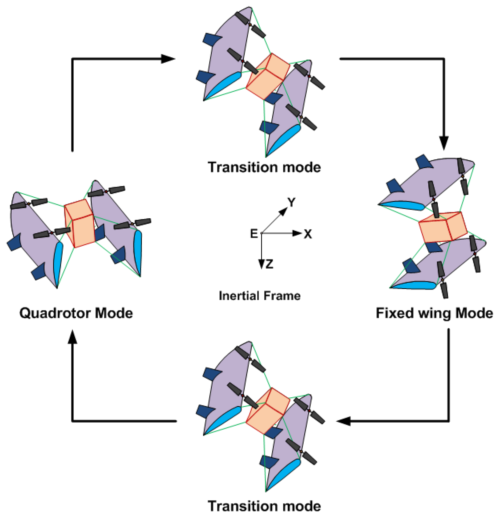
2. Mathematical Model and Control Architecture of Biplane Quadrotor

The flight envelope of the biplane quadrotor can be divided into three modes: (i) Quadrotor Mode, (ii) Transition mode, and (iii) Fixed-wing mode, as shown in Figure 1. During the take-off, landing, and hover, the biplane quadrotor is operated in the quadrotor mode. After performing the transition maneuver, it will convert to a conventional fixed-wing aircraft that can fly with high velocity. For this simulation study, we assume that the mass of the biplane quadrotor is 12 kg. In general, drone motors are chosen in such a way that the total thrust generated by all motors is about 1.5 times higher than the weight of the drone. We consider this as a physical constraint during the simulation. So maximum thrust generated by the motors is 12 × 1.5 = 18 N and torque is 9 N-m.
In this simulation study, only the quadrotor mode is considered, where the wings generate no aerodynamic forces and moments, and its dynamics are described the same as the conventional quadrotor, so the state space representation of the dynamics of the biplane quadrotor in the quadrotor model [12] is given as
x ˙ 1 x ˙ 2 x ˙ 3 x ˙ 4 x ˙ 5 x ˙ 6 x ˙ 7 x ˙ 8 x ˙ 9 x ˙ 10 x ˙ 11 x ˙ 12 = x 2 ( b 1 x 6 + b 2 x 2 ) x 4 + b 3 L t + b 4 N t + d ϕ x 4 b 5 x 2 x 6 b 6 ( x 2 2 x 6 2 ) + b 7 M t + d θ x 6 ( b 8 x 2 b 2 x 6 ) x 4 + b 4 L t + b 9 N t + d ψ x 8 g T m c x 1 c x 3 + d z x 10 T m U x + d x x 12 T m U y + d y ,
where s ( · ) = sin ( · ) and c ( · ) = cos ( · ) . To avoid singularities, roll, and pitch are bounded in ( π / 2 π / 2 ) for yaw angle ( π π ) , [ L t M t N t ] , T are the moments and thrust, [ d ϕ d θ d ψ ] and [ d x d y d z ] are the external disturbance acting on attitude and position subsystem of the biplane quadrotor, g is gravitational force. U x = s x 1 s x 5 + c x 1 s x 3 c x 5 , U y = s x 1 c x 5 + c x 1 s x 3 c x 5 , and inertial constants are
b 1 b 2 b 3 b 4 b 8 b 9 = 1 I x I z I x z 2 ( I y I z ) I z I x z 2 ( I x I y + I z ) I x z I z I x z ( I x I y ) I x + I x z 2 I x , b 5 b 6 b 7 = 1 I y ( I z I x ) I x z 1 .
Based on the above, the biplane dynamics control architecture is proposed next. The block diagram of the proposed dual observer based controller is shown in Figure 2.
The ESO estimates position, attitude, and linear and angular velocities. The DO estimates the external disturbances based on the estimated state by ESO and known control inputs (L). The error signals are generated based on the estimated signals x ^ and desired signals, further, based on these signals the controller gives a command (L) to the variable pitch propulsion system, and the signal U is generated for the four motors. The main advantages of the proposed controller architecture over the existing methods are simple yet efficient, practical, easy to implement on actual hardware, and energy-efficient. ESO is introduced to approximate the linear as well as the angular position and velocity of the biplane quadrotor while it operates in the quadrotor mode.

3. Observers for Controller Design

The ESO for the second-order system can be intended as
l ˙ 1 = l 2 , l ˙ 2 = f ( x n ) + d ϵ + b 0 U s ,
where f ( x n ) is the nonlinear function, n = 1 12 , d ϵ is the external disturbance acting on the attitude and position subsystem of the biplane quadrotor, b 0 is the controlling factor, and s is [ M t N t N t T ] . For the above second-order system, ESO is designed as
E k = e m = ζ 1 ι x m ζ ˙ 1 ι = ζ 2 ι η 1 ι e m ζ ˙ 2 ι = ζ 3 ι η 2 ι · l f ( e m , χ 1 , μ ) + b 0 U s ζ ˙ 3 ι = η 3 ι · l f ( e m , χ 2 , μ ) ,
where η 1 , η 2 , η 3 , χ 1 , χ 2 and μ are the set parameter, ι = [ ϕ θ ψ z x y ] and m = [ x 1 x 3 x 5 x 7 x 9 x 11 ] . l f ( e x m , χ , μ ) is the saturation function that regulates signal chattering, and this function is given by
l f ( e m , χ , μ ) = e m μ 1 χ , | e m | μ | e m | χ · s i g n ( e m ) , | e m | > μ .
Using this equation, we design ESO for the roll subsystem:
x ˙ 1 = x 2 , x ˙ 2 = ( b 1 x 6 + b 2 x 2 ) x 4 + b 3 L t + b 4 N t + d ϕ ,
such that
E ϕ = e x 1 = ζ 1 ϕ x 1 ζ ˙ 1 ϕ = ζ 2 ϕ η 1 ϕ e x 1 ζ ˙ 2 ϕ = ζ 3 ϕ η 2 ϕ · l f ( e x 1 , χ 1 , μ ) + b 0 L t ζ ˙ 3 ϕ = η 3 ϕ · l f ( e x 1 , χ 2 , μ ) , l f ( e x 1 , χ , μ ) = e x 1 μ 1 χ , | e x 1 | μ | e x 1 | χ · s i g n ( e x 1 ) , | e x 1 | > μ .
The ESO for all states of the biplane quadrotor is designed using a similar procedure.

3.1. Stability Analysis of ESO

In this section, we discuss stability analysis [27], and for that the Lyapunov positive definite function V e of the Extended State Observer (ESO) is deliberated, and the error dynamics are defined as
e s 1 = ζ x e ˙ s 1 = e s 2 η 1 e s 1 e ˙ s 2 = e s 3 η 2 l f ( e s 1 ) e ˙ s 3 = η 2 l f ( e s 1 ) .
We can rewrite the above equation in the matrix format as
e ˙ s = Λ ( e s ) e s , e s = [ e s 1 , e s 2 , e s 3 ] T , Λ = η 1 1 0 η 2 ρ 0 1 η 3 ρ 0 0 ,
where ρ = l f ( e s 1 ) / e 1 > 0 and it is bounded. Then, the theorem below details an adequate constraint for the stability of the ESO in Equation (3).
Theorem 1.
In the third order dynamics of the ESO in Equation (3) with the observer gains which satisfy  η i > 0 ( i = 1 3 ) , and η 1 , η 2 > η 3 , there exists a matrix Γ in which all main diagonal elements are positive and Γ · Λ is a symmetric non-negative definite matrix such that the zero equilibrium point of the ESO is asymptotically stability [27].
Proof. 
Matrix Γ is chosen as
Γ = γ 11 γ 12 γ 13 γ 12 γ 22 γ 23 γ 13 γ 23 γ 33 .
For the analysis simplification, the element’s value of the main diagonal is allocated as
γ 11 = 1 , γ 22 = γ 33 = Π .
The Lyapunov function for Equation (4) is defined as
V e = 0 t ( Γ · Λ ( e s ) e s , e ˙ s ) d T .
If the matrix Γ · Λ is positive definite, then V e also becomes a positive definite Lyapunov function, and using Equation (4) and (5), the matrix H is translated to
H = h 11 1 γ 12 h 21 γ 12 Π h 31 γ 13 γ 23 ,
where
h 11 = η 1 + γ 12 η 2 ρ + γ 13 η 3 ρ ,
h 21 = γ 12 η 1 + Π η 2 ρ + γ 23 η 3 ρ ,
h 31 = γ 13 η 1 γ 23 η 2 ρ + Π η 3 ρ .
The elements of matrix H are defined as
h 21 = 1 , h 31 = γ 12 , h 13 = Π .
By combining Equations (8) and (11) to calculate two elements of matrix Γ as
γ 12 = η 2 η 1 η 2 η 3 + Π ρ η 1 2 + η 2 ρ + η 1 η 3 ρ η 1 η 2 η 3 Π ( η 1 + η 3 ρ ) ,
γ 23 = 1 ρ · 1 η 1 η 2 η 3 Π ρ η 1 2 + η 2 ρ + η 1 η 3 ρ η 1 η 2 η 3 ,
since η i > 0 , i = 1 , 2 , 3 and η 1 η 2 > η 3 , if Π 0 + , the principal minor determinant of matrix H are calculated as
h 11 = η 1 + η 2 ρ ( Π η 1 + η 2 1 + Π η 1 2 + Π η 2 ρ + Π η 1 η 2 ρ η 1 η 2 η 3 ) Π η 3 ρ = η 1 + η 2 2 ρ η 1 η 2 η 3 Π ρ ( η 1 η 2 + η 3 ) + ρ 2 η 2 η 3 η 2 2 ρ η 1 2 + η 2 ρ + η 1 η 3 ρ η 1 η 2 η 3 η 1 + η 2 2 ρ η 1 η 2 η 3 > 0 .
h 11 1 h 21 γ 12 = h 11 · γ 21 1 = ( η 1 + η 2 ρ η 1 η 3 η 3 σ 1 ) ( Π η 1 + η 2 1 + Π η 1 2 + Π η 2 ρ + Π η 1 η 2 ρ η 1 η 2 η 3 ) 1 ( η 1 + η 2 2 ρ η 1 η 2 η 3 ) η 2 η 1 η 2 η 3 1 = η 3 + η 2 3 ρ η 1 η 2 η 3 > 0 .
h 11 1 γ 12 h 12 γ 12 Π h 31 γ 13 γ 23 = h 11 ( γ 12 γ 23 Π 2 ) 2 Π γ 12 γ 23 γ 12 3 h 11 γ 23 2 η 2 ρ γ 23 ( γ 23 η 2 ρ ) 3 = h 11 η 2 ( η 1 η 2 η 3 ) 2 ρ η 2 η 1 η 2 η 3 3 1 ( η 1 η 2 η 3 ) ρ = η 3 ( η 1 η 2 η 3 ) 2 ρ > 0 .
Using (8)–(16), we observe that the principal minor determinants of H are positive, resulting in a symmetric positive definite matrix H. Therefore, there is a matrix Γ that fulfills Theorem 1. Replacing matrix Γ into (6), we have
V e = 0 t ( Λ ( e s ) e s ) T Γ Λ ( e s ) e s d T = 0 t η 1 e s 1 e s 2 2 Π η 2 l f e s 1 e s 3 2 Π η 3 l f ( e s 1 ) 2 d T .
Based on the above equations, the time derivative is
V ˙ e = ( η 1 e s 1 e s 2 ) 2 Π η 2 l f ( e s 1 ) e s 3 2 Π ( η 3 l f ( e s 1 ) ) 2 0 .
The above analysis only depends on the central diagonal component of Γ , and V ˙ e is non-positive semi-definite. So, if V e ( e s 1 , e s 2 , e s 3 ) is bounded, then the errors e s 1 , e s 2 , and e s 3 are bounded, and then we can say that V ˙ e is also bounded which proves that the stability requirement of ESO. □
Next, we design DO to estimate external disturbances. Some assumptions are required for simplicity and effectiveness in the nonlinear disturbance observer design [9] such that
| | d ˙ p ( t ) | | D p , | | d ˙ o ( t ) | | D o t > 0 .
For the position subsystem of a biplane quadrotor [9], a DO is given as
n ˙ p = L p n p L p L p P ˙ + G + 1 m a U p , d ^ p = n p + L p P ˙ ,
where U p = R ( O ) E 3 U 1 , d ^ p is the disturbance approximation, is the observer state vector n p , tunable gain matrix L p > 0 and G = [ 0 0 g ] T .
Next, we design a nonlinear controller based on the BSC and ITSMC, and the block diagram of the controller design is shown in Figure 2 where the controller is designed based on the states and external disturbances estimated by the ESO as well as DO in the quadrotor mode.

3.2. Backstepping Controller Design

For ease of calculation, we divide biplane quadrotor dynamics into six subsystems. First, let us take the roll subsystem as
ζ ˙ 1 ϕ = ζ 2 ϕ , ζ ˙ 2 ϕ = ( b 1 ζ 2 ψ + b 2 ζ 2 ϕ ) ζ 2 θ + b 3 L t + b 4 N t + d ϕ .
As in (19), a DO for the roll subsystem is designed as
n ˙ ϕ = L ϕ ( n ϕ + L ϕ ζ ˙ 1 ϕ + ( b 1 ζ 2 ψ + b 2 ζ 2 ϕ ) ζ 2 θ + b 3 L t + b 4 N t ) , d ^ ϕ = n ϕ + L ϕ ζ 2 ϕ .
Differentiating d ^ ϕ , we get
d ^ ˙ ϕ = n ˙ ϕ + L ϕ x ˙ 2 = L ϕ n ϕ L ϕ ( L ϕ ζ ˙ 1 ϕ + ( b 1 ζ 2 ψ + b 2 ζ 2 ϕ ) x 4 + b 3 L t + b 4 N t ) + L ϕ ( ( b 1 ζ 2 ψ + b 2 ζ 2 ϕ ) ζ 2 θ + b 3 L t + b 4 N t + d ϕ ) L ϕ ( n ϕ + L ϕ ζ 2 ϕ ) + L ϕ d ϕ , = L ϕ d ˜ ϕ ,
where d ˜ ϕ = d ϕ d ^ ϕ is the estimation error, and d ^ ϕ is the estimated disturbance and L ϕ > 0 is a tunable gain. Stability analysis of the DO is available in our previous work [9], and so in this work, we only focus on the overall stability analysis and control law design. Let us define error in the roll angle as e 1 = ζ 1 ϕ x 1 d with ζ 1 ϕ as the estimated roll angle and x 1 d as the desired roll angle. Based on the error, a positive definite function is given as V 1 = 1 2 e 1 2 and the time derivative is
V ˙ 1 = e 1 e ˙ 1 = e 1 ( ζ ˙ 1 ϕ x ˙ 1 d ) = e 1 ( ζ 2 ϕ x ˙ 1 d ) .
A virtual control signal x 2 d = x ˙ 1 d k 1 e 1 where k 1 > 0 is designed so that
V ˙ 1 = e 1 e 2 k 1 e 1 2 ,
and the error in roll angle rate become e 2 = ζ 2 ϕ x 2 d = ζ 2 ϕ x ˙ 1 d + k 1 e 1 . In the next stage, to improve the function V 1 with error in the roll angle rate e 2 , the error dynamics e ˙ 2 = x ˙ 2 x ¨ 1 d + k 1 e ˙ 1 and again based on this error term, Lyapunov positive definite function is given as
V 2 = V 1 + 1 2 e 2 2 ,
and the time derivative is given as
V ˙ 2 = e 1 e 2 k 1 e 1 2 + e 2 ( ( b 1 ζ 2 ψ + b 2 ζ 2 ϕ ) ζ 2 θ + b 3 L t + b 4 N t + d ^ ϕ ) .
Using (22) and (24), a control law is designed for the roll subsystem as
L t = 1 b 3 ( e 1 e 2 k 2 + x ¨ 2 d k 1 e ˙ 1 b 1 ζ 2 ψ b 2 ζ 2 ϕ ζ 2 θ b 4 N t d ^ ϕ ) ,
such that V ˙ 2 = k 1 e 1 2 k 2 e 2 2 0 , k 1 , k 2 > 0 which ensure that error becomes zero. Using similar calculations, the control laws for the remaining subsystems are
M t = 1 b 7 ( e 3 k 4 e 4 + x ¨ 3 d e ˙ 3 k 3 b 5 ζ 2 ϕ ζ 2 ψ + b 6 ζ 2 ϕ 2 ζ 2 ψ 2 d ^ θ ) ,
N t = 1 b 9 ( e 5 k 6 e 6 e ˙ 5 k 5 ( b 8 ζ 2 ϕ b 2 ζ 2 ψ ) ζ 2 θ b 4 L t d ^ ψ + x ¨ 5 d ) ,
T = m c ζ 1 ϕ c ζ 1 θ ( e 7 + k 8 e 8 x ¨ 7 d + e ˙ 7 k 7 + g + d ^ x k 7 e ˙ 7 ) ,
U x = m T e 9 + k 10 e 10 x ¨ 9 d + d ^ x + e ˙ 9 k 9 ,
U y = m T e 11 + k 12 e 12 x ¨ 11 d + d ^ y + e ˙ 11 k 11 .
where k i > 0 , i = 3 , , 12 are tunable gains.

3.3. ITSMC Controller Design

Due to the integrator action, there is a reduced chattering phenomenon in the ITSMC, less than SMC and TSMC. A second-order sliding controller which uses the first derivative of the control signals rather than the actual control as control [39] can eliminate chattering. However, for the present application, reduced chattering is adequate. Let us define the sliding function [11,40] as
S = e I ˙ + ω e ˙ b / a + τ e b 2 a 1 d t .
In addition, the reaching law is carefully chosen as
S ˙ = S ε s i g n ( S ) ,
where 0 < b / a < 1 , ω , τ , ε , > 0 . and e I is a state tracking error term. Now let us consider the altitude subsystem (1):
ζ ˙ 1 z = ζ 2 z , ζ ˙ 2 z = g T m c ζ 1 ϕ c ζ 1 θ + d z .
As shown in the block diagram (Figure 2), the error in the z axis is given by e z = ζ 1 z z d where ζ 1 z is the estimated z axis position by the ESO. Based on this, a Lyapunov positive definite function is defined as V z = 1 2 S z 2 . Now, its time-derivative using (33) is
V ˙ z = S z ζ 1 z ¨ z ¨ d + ω z e ˙ z b z / a z + τ z e z b z 2 a z 1 , = S z g T m c ζ 1 ϕ c ζ 1 θ + d ^ z z ¨ d + ω z e ˙ z b z / a z + τ z e z b z 2 a z 1 .
The control law is designed using (34) as
T = m ζ 1 ϕ c ζ 1 θ ( g + d ^ z z ¨ d + ω z e ˙ z b z / a z + τ z e z b z 2 a z + b z + z S z + ε z s i g n S z ) .
such that V ˙ z = z S z 2 ε z | S z | 0 , where z , ε z > 0 .
Using the same method, the control laws are defined as
L t = 1 b 3 ( ( b 1 ζ 2 ψ + b 2 ζ 2 ϕ ) ζ 2 θ b 4 N t d ^ ϕ + ϕ ¨ d ω ϕ e ˙ ϕ b ϕ / a ϕ τ ϕ e ϕ b ϕ 2 a ϕ + b ϕ ) , ϕ , ε ϕ > 0 ,
M t = 1 b 7 ( b 5 ζ 2 ϕ ζ 2 ψ + b 6 ζ 2 ϕ 2 ζ 2 ψ 2 d ^ θ + θ ¨ d ω θ e ˙ θ b θ / a θ τ θ e θ b θ 2 a θ + b θ ) , θ , ε θ > 0 ,
N t = 1 b 9 ( ( b 8 ζ 2 ϕ b 2 ζ 2 ψ ) ζ 2 θ b 4 L t + x ¨ 5 d d ^ ψ ω ψ e ˙ ψ b ψ / a ψ τ ψ e ψ b ψ 2 a ψ + b ψ ) , ψ , ε ψ > 0 ,
U x = T m ( x ¨ d + ω x e ˙ x b x / a x + τ x e x b x 2 a x b x + x S x d ^ x + ε x s i g n S x ) , x , ε x > 0 ,
U y = T m ( y ¨ d + ω y e ˙ y b y / a y + τ y e y b y 2 a y b y + d ^ y + y S y + ε y s i g n S y ) . y , ε y > 0 .
In the next section, we derive the adaptive backstepping and adaptive hybrid controller.

4. Adaptive Controller Design

An adaptive controller is required to handle mass change during the flight. As per the dynamics of the biplane quadrotor, the position subsystem is directly affected during the mass change, so only the position subsystem is considered to derive the adaptive BSC and adaptive hybrid controller with ESO and DO. Control laws for the attitude subsystem remain the same as derived earlier.

4.1. Adaptive Backstepping Controller

We derive the adaptive backstepping controller for handling the mass change during the flight and wind gust disturbance. Let us consider the positioning subsystem, and the state space representation of this system is given as
x ˙ 7 x ˙ 8 x ˙ 9 x ˙ 10 x ˙ 11 x ˙ 12 = x 8 g T λ c ζ 1 ϕ c ζ 1 θ + d z x 10 T λ U x + d x x 12 T λ U y + d y ,
where λ = 1 / m , m uncertain mass and λ ˜ = λ λ ^ . First, we define error in altitude, x, and y position as
e 7 = ζ 1 z x 7 d , e 9 = ζ 1 x x 9 d , e 11 = ζ 1 y x 11 d ,
and the error in velocity as
e 8 = ζ 2 z x 8 d , e 10 = ζ 2 x x 10 d , e 12 = ζ 2 y x 12 d .
Lyapunov positive definite function for the positioning subsystem is defined as
V p = i = 7 , 9 , 11 1 2 e i 2 ,
and the time derivative is
V ˙ p = i = 7 , 9 , 11 e i e ˙ i = e 7 ζ ˙ 1 z x ˙ 7 d + e 9 ζ ˙ 1 x x ˙ 9 d + e 11 ζ 1 y ˙ x 11 d ˙ .
For stabilization, the virtual control laws are defined as
x 8 d = x ˙ 7 d k 7 e 7 , x 10 d = x ˙ 9 d k 9 e 9 , x 12 d = x ˙ 11 d k 11 e 11 ,
so that
V ˙ p = e 7 e 8 k 7 e 7 2 + e 9 e 10 k 9 e 9 2 + e 11 e 12 k 11 e 11 2 .
The next step is to enhance the V p with velocity error and the error of mass:
V v = i = 8 , 10 , 12 1 2 e i 2 + 1 2 δ b λ ˜ 2 .
The time derivative of the above function is expressed as
V ˙ v = e 8 ( ζ ˙ 2 z x ˙ 8 d ) + e 10 ( ζ ˙ 2 x x ˙ 10 d ) + e 12 ( ζ ˙ 2 y x ˙ 12 d ) 1 δ b λ ˜ λ ^ , = e 8 ( g T λ c ζ 1 ϕ c ζ 1 θ + d z x ¨ 7 d + k 7 e ˙ 7 ) + e 10 ( T λ U x + d x x ¨ 9 d + k 9 e ˙ 9 ) + e 12 ( T λ U y + d y x ¨ 11 d + k 11 e ˙ 11 ) 1 δ b λ ˜ λ ^ ˙ .
The adaptive Law is defined as
λ ^ ˙ = e 8 ( T c ζ 1 ϕ c ζ 1 θ ) e 10 ( T U x ) e 12 ( T U y ) δ b , δ b > 0 ,
and the control laws for the position subsystem are
T = 1 λ ^ c ζ 1 ϕ c ζ 1 θ e 7 + k 8 e 8 x ¨ 7 d + e ˙ 7 k 7 + g + d ^ z k 7 e ˙ 7 ,
U x = 1 λ ^ T e 9 + k 10 e 10 x ¨ 9 d + d ^ x + e ˙ 9 k 9 ,
U y = 1 λ ^ T e 11 + k 12 e 12 x ¨ 11 d + d ^ y + e ˙ 11 k 11 ,
such that
V ˙ v = i = 7 12 k i e i 2 ,
where k i > 0 . The above adaptive BSC controller is updated when there is mass change.

4.2. Adaptive Hybrid Controller Design

Next, to design an adaptive hybrid controller to handle mass change and wind gust disturbance during flight, let us consider the state space representation of the positioning subsystem (41). An adaptive hybrid controller is shown in Figure 3 where desired signals [ x d y d z d ] and [ ψ d ] are given to the ITSMC and BSC controller, respectively. ESO estimates the attitude subsystem state [ ζ o ] and position subsystem state [ ζ p ] . DO use the estimated state and control inputs to estimate the external disturbances. Desired roll and pitch angles are calculated using the control signal generated by the ITSMC. BSC controller generates roll, pitch, and yaw moments [ L T M t N t ] and ITSMC generates the desired thrust force T and gives it to the variable pitch propulsion system, and based on the input signal; it generates the signal [ U ] given to the respective actuators. Adaptive Law is designed based on the sliding surface and estimated roll and pitch angles. ITSMC controller updated based on adaptive Law to handle the mass change.
To design an adaptive hybrid controller, sliding function (31) is modified with h indicating the hybrid controller:
S h = e h ˙ + ω h e ˙ h d / c + τ h e h d 2 c 1 d t ,
and the reaching Law is selected as
S ˙ h = h S h ε h s i g n ( S h ) ,
where 0 < d / c < 1 , ω h , τ h , ε h , h > 0 . We define the errors in altitude, x and y position as
e h 7 = ζ 1 z x 7 d , e h 9 = ζ 1 x x 9 d , e h 11 = ζ 1 y x 11 d .
Using (49) and (50), the Lyapunov positive function for the position subsystem is
V p = i = 7 , 9 , 11 S h i + 1 2 δ h λ ˜ 2 .
Taking the time-derivative of the above equation, we get
V ˙ p = S h 7 S ˙ h 7 + S h 9 S ˙ h 9 + S h 11 S ˙ h 11 λ ˜ λ ^ ˙ δ h .
Using (41), (49) and (50), the adaptive law is designed as
λ ^ ˙ = S h 7 ( T c ζ 1 ϕ c ζ 1 θ ) S h 9 ( T U x ) S h 11 T U y δ h ,
where δ h > 0 , and the control laws for the position subsystem are
T = 1 λ ^ c ζ 1 ϕ c ζ 1 θ ( g + d ^ z x ¨ 7 d + ω h 7 e ˙ h 7 d h 7 / c h 7 + h 7 S h 7 + τ h 7 e h 7 d h 7 2 c h 7 + d h 7 + ε h 7 s i g n ( S h 7 ) ) , h 7 , ε h 7 > 0 ,
U x = T λ ^ ( x ¨ 9 d + d ^ x + ω h 9 e ˙ h 9 d h 9 / c h 9 + τ h 9 e h 9 d h 9 2 c h 9 d h 7 + h 9 S h 9 + ε h 9 s i g n ( S h 9 ) ) , h 9 , ε h 9 > 0 ,
U y = T λ ^ ( x ¨ 11 d + d ^ y + ω h 11 e ˙ h 11 d h 11 / c h 11 + τ h 11 e h 11 d h 11 2 c h 11 d h 11 + h 11 S h 11 + ε h 11 s i g n ( S h 11 ) ) , h 11 , ε h 11 > 0 ,
so that V ˙ p 0 . The BSC controls the attitude subsystem, while the adaptive ITSMC controls the position subsystem. Next, we show the results of the different controllers plus ESO and with and without DO for the trajectory tracking despite wind gusts.

5. Results and Discussions

Table 1 gives the biplane quadrotor’s parameters for this simulation study. For the wind gusts, we adopt the von Kármán wind turbulence model [41], a mathematical model of continuous wind gusts which is not only better than the Dryden wind turbulence model but also used by the USDOD (United States Department of Defense). The biplane quadrotor’s initial position and attitude are [ 0 0 0 ] . Then, the simulation is carried out for 180s, where all possible changes are applied, and the result of controller pulse ESO with and without DO is shown.
Figure 4 shows the position tracking by the ESO-based BSC with and without DO. The response of the ESO-based BSC with DO is faster with less overshoot than the ESO-based BSC, which shows the effectiveness of the disturbance observer. Figure 4 also shows y axis tracking by the ESO-based BSC, which has more fluctuations and higher overshoot than ESO-based BSC with DO. The effect of disturbance is significant in the y axis. Furthermore, altitude tracking by the ESO-based BSC with and without DO reveals that ESO-based BSC generates a significant error than the ESO-based BSC with DO, thereby showing the effectiveness of the designed nonlinear disturbance observer.
Position subsystem tracking by the ESO-based ITSMC controller with and without DO is shown in Figure 5. ESO-based ITSMC with DO handles wind gusts more efficiently. The x axis tracking by ESO-based ITSMC with DO generates less overshoot and less settling time and similar responses like y and z axis tracking, showing the effectiveness of the designed nonlinear disturbance observer. Results show that the ESO-based controller with DO is more effective than the ESO-based controller without DO. Next is, the responses of the ESO-based BSC, ITSMC, and the HC with DO.
Trajectory tracking of the positioning subsystem shown in Figure 6 reveals that the ESO-based HC with DO has less overshoot than the ESO-based BSC with DO and has a faster response than the ESO-based ITSMC with DO while tracking x and y axes. Furthermore, the ESO-based HC with DO generates less overshoot for altitude tracking than the ESO-based BSC with DO.
Figure 7 shows a comparison between tracking the attitude of the biplane quadrotor by the ESO-based HC, BSC, and ITSMC with DO. Here note that the desired roll and pitch angles are calculated based on the U x , U y while desired ψ angle is calculated based on x-y trajectory. That is why the desired angles are not shown. Note that the pitch and roll angles are bounded in ± 89 . Roll, pitch, and yaw angle tracking by the ESO-based HC with DO are far better than the ESO-based BSC with DO, and ESO-based ITSMC DO. Simulation results of position and attitude subsystems show that the ESO-based HC has the advantage of both BSC and ITSMC.
Next, the responses of the ESO-based ABSC + DO and ESO-based AHC with ESO and DO are compared with mass change during the flight despite wind gusts. Initially, the net mass of the vehicle is 18 kg. Then, at t = 50 s, it is commanded to drop a 6 kg weight. Again at t = 80 s, it gains 6 kg weight along with wind gusts. Two sudden changes in the mass applied in the biplane quadrotor require careful analysis of the response of the ESO-based adaptive BSC and adaptive HC with DO. Figure 8 shows the x-y axis trajectory tracking by the ESO-based adaptive controllers with DO. A slight fluctuation is observed with the ESO-based adaptive hybrid controller with DO. However, the ESO-based ABSC + DO controller generates a comparatively large overshoot during x axis tracking. In y axis tracking, a 0.044 m steady-state error is generated by the ESO-based ABSC DO. ESO-based HC with DO is more effective in the y axis tracking in the presence of wind gusts and mass change with no steady-state error.
Figure 9 shows the altitude tracking by the ESO-based ABSC and AHC with DO during mass change, which reveals a steady-state error of 0.01 m generated by the ESO-based ABSC + DO with a change in the mass. In addition, the ESO-based AHC can track the desired altitude after the mass change, showing the effectiveness of the ESO-based AHC + DO. Figure 10 shows attitude tracking by the ESO-based adaptive controller with DO. The ESO-based AHC with DO responds better than the ESO-based ABSC with DO while tracking the roll and pitch angle. In addition, yaw angle tracking by the ESO-based AHC with DO generates lesser error than the ESO-based ABSC + DO.

6. Conclusions

In this paper, simulation is carried out using MATLAB Simulink to evaluate the ESO-based controllers with and without DO for trajectory tracking and ESO-based adaptive controllers with DO for mass adaptation during the mission. The results of these controllers reveal that
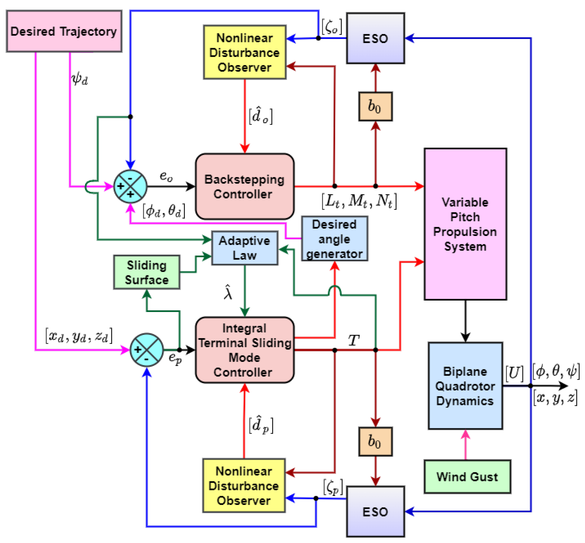
  • ESO estimates the position, altitude, and velocity using only position and attitude signals, and DO estimates the disturbance signal applied on a biplane quadrotor.
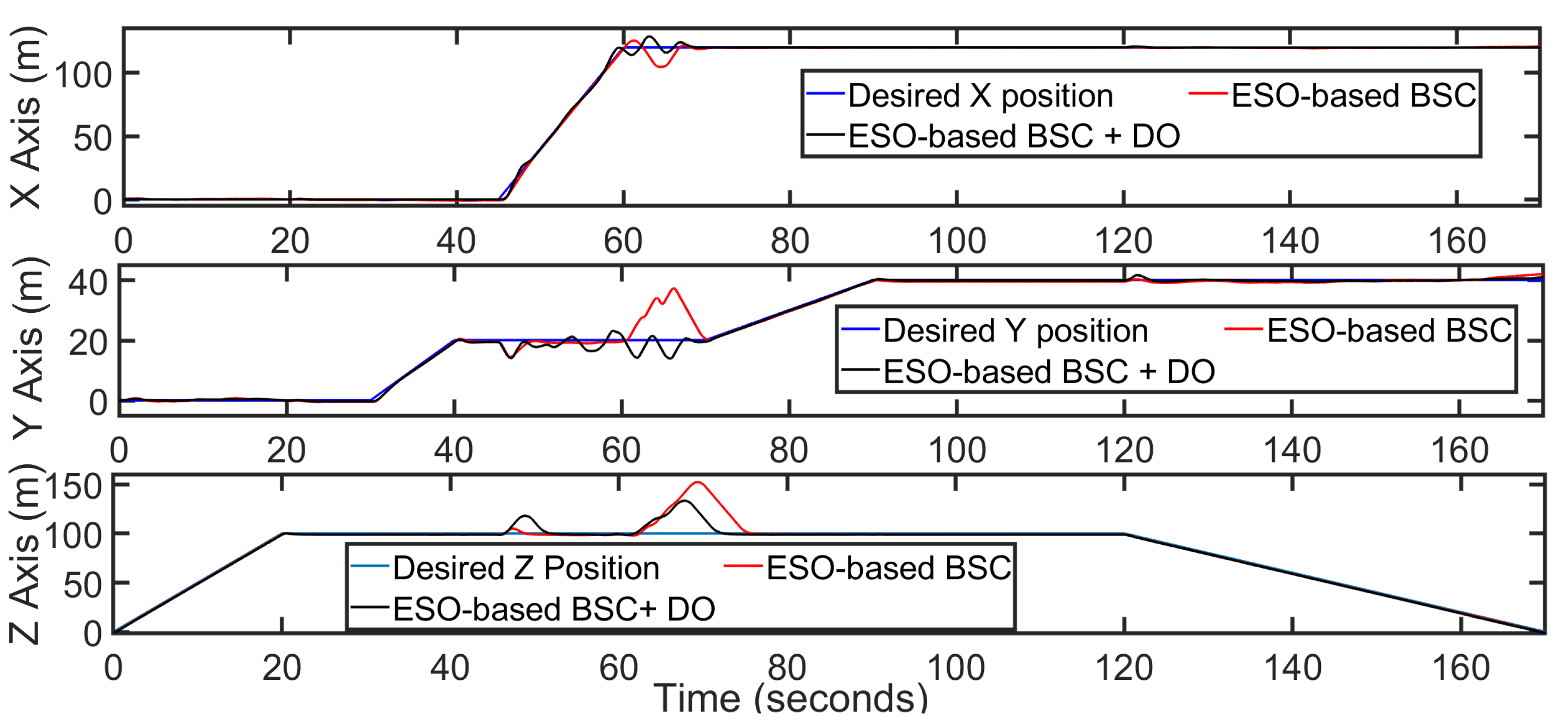
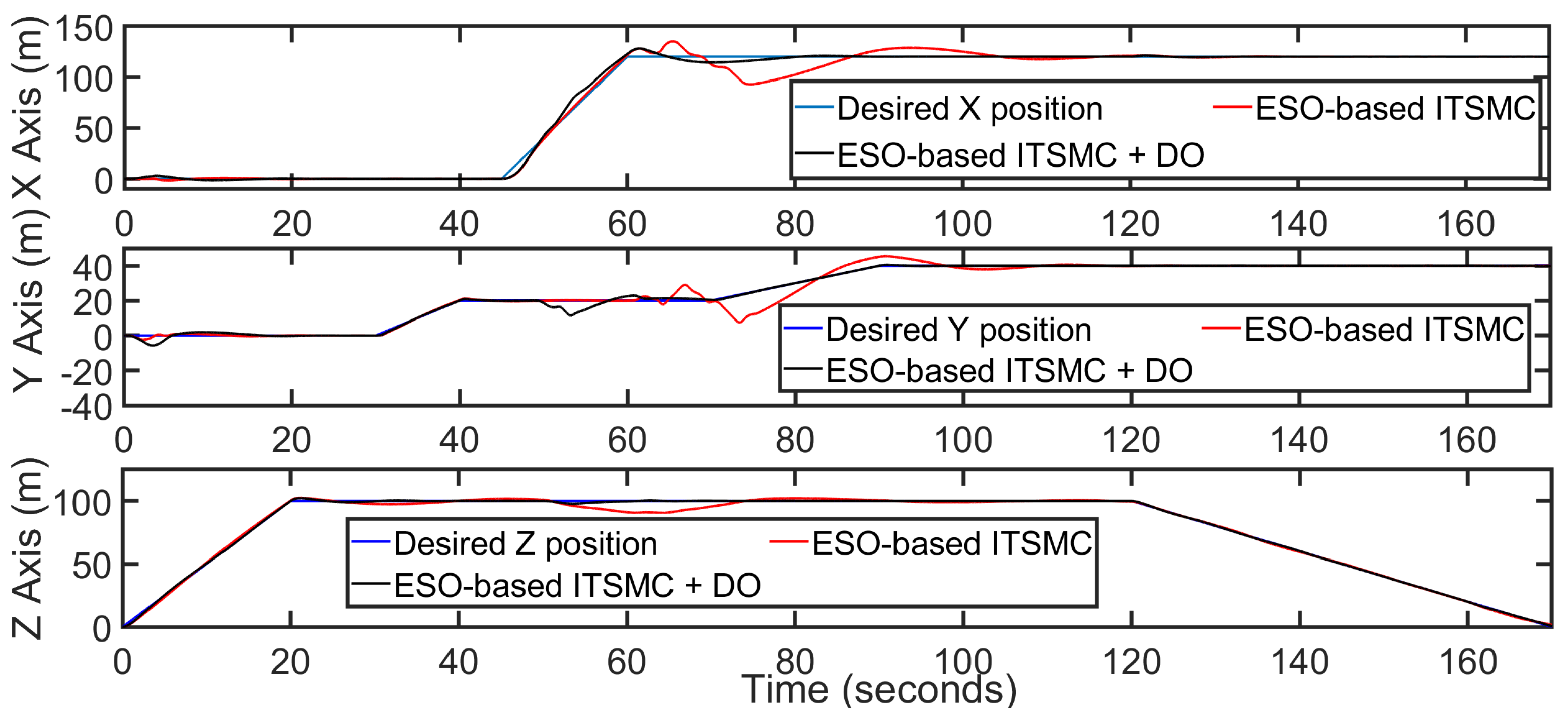
  • x axis trajectory tracking by the ESO-based BSC with DO has a faster response, but overshoot is significant in comparison. ESO-based ITSMC with DO has a sluggish response, but ESO-based HC + DO has a faster response than the ESO-based ITSMC + DO, and less overshoot than the ESO-based BSC + DO.
  • The ESO-based HC + DO is the faster and most effective controller among these three controllers.
  • In altitude tracking, ESO-based ITSMC + DO has less overshoot than the other two controllers.
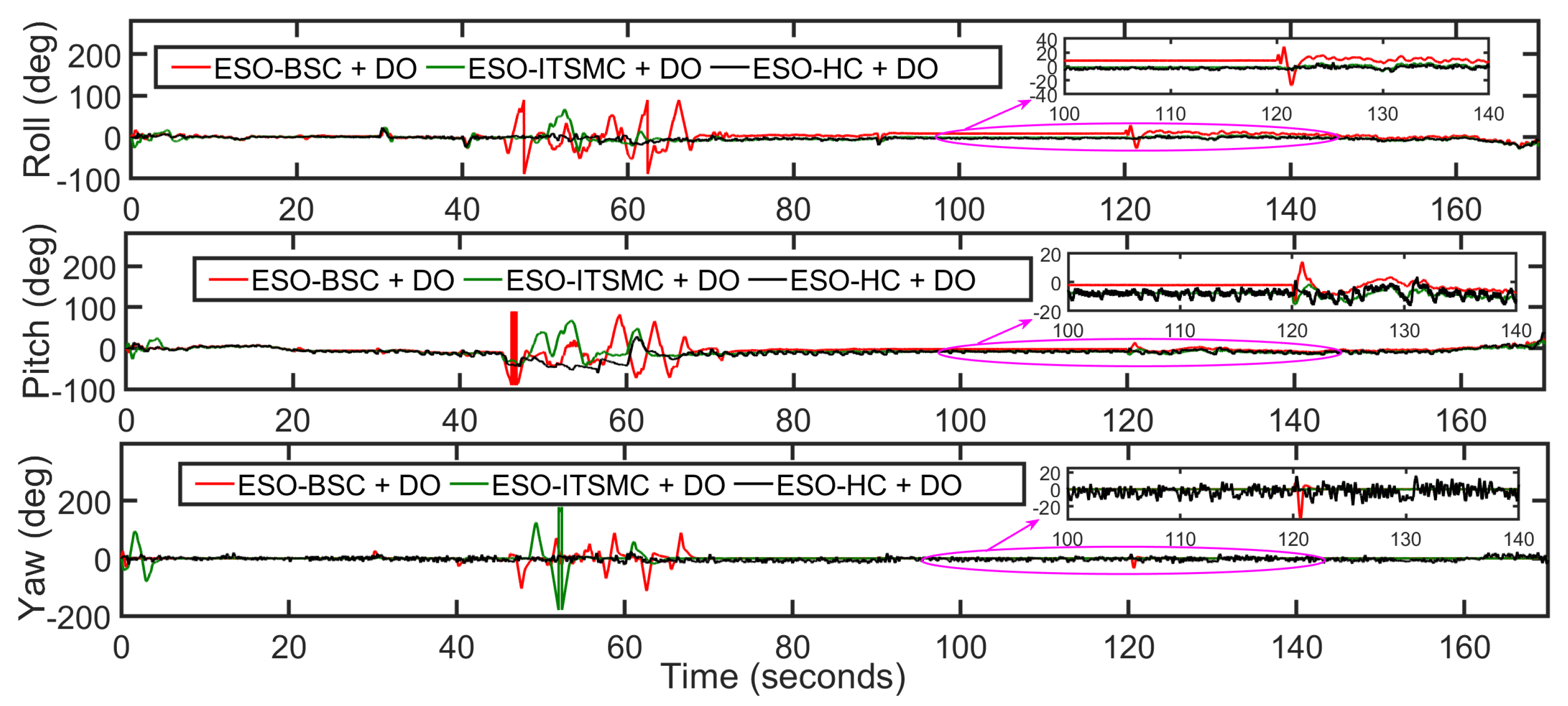
  • Attitude tracking by the ESO-based HC + DO is better than ESO-based BSC, and ITSMC with DO.
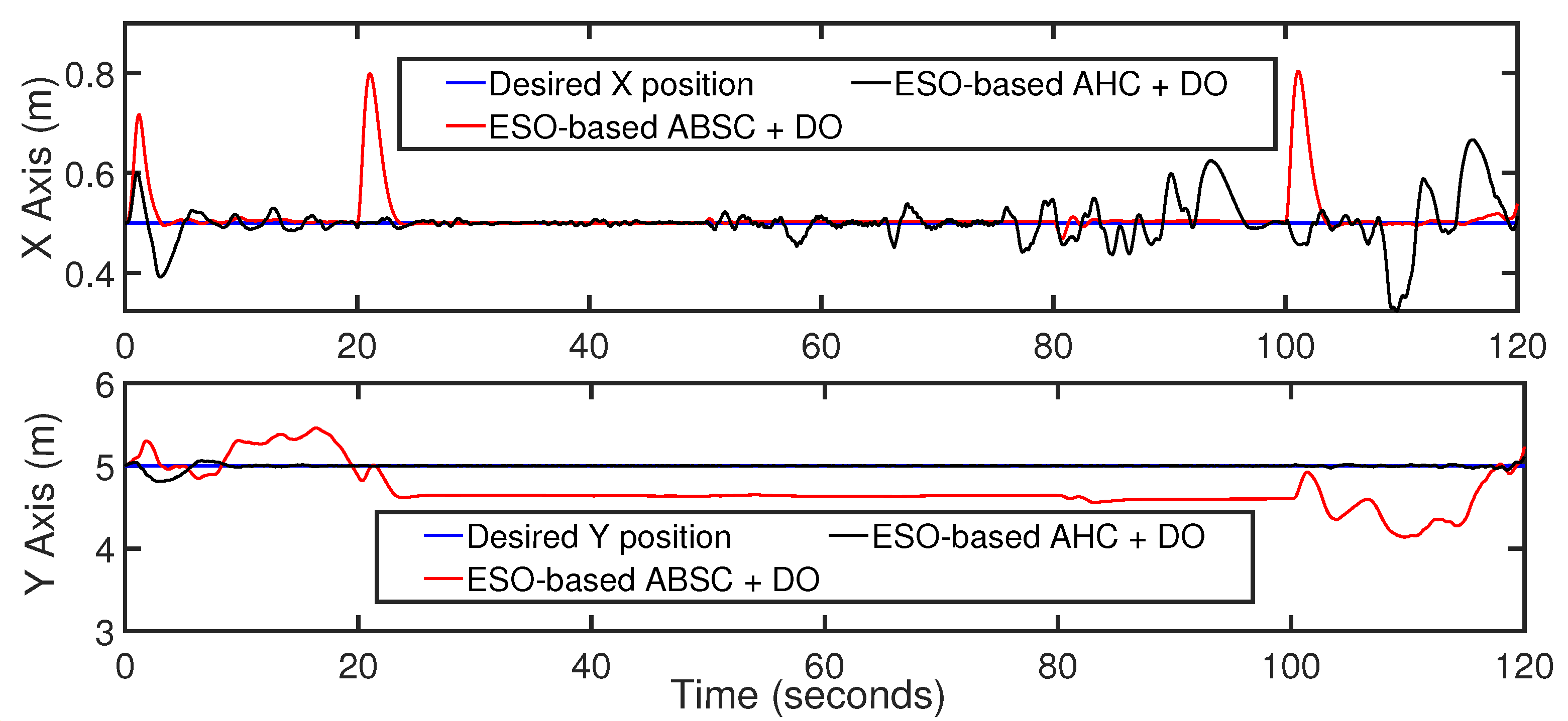
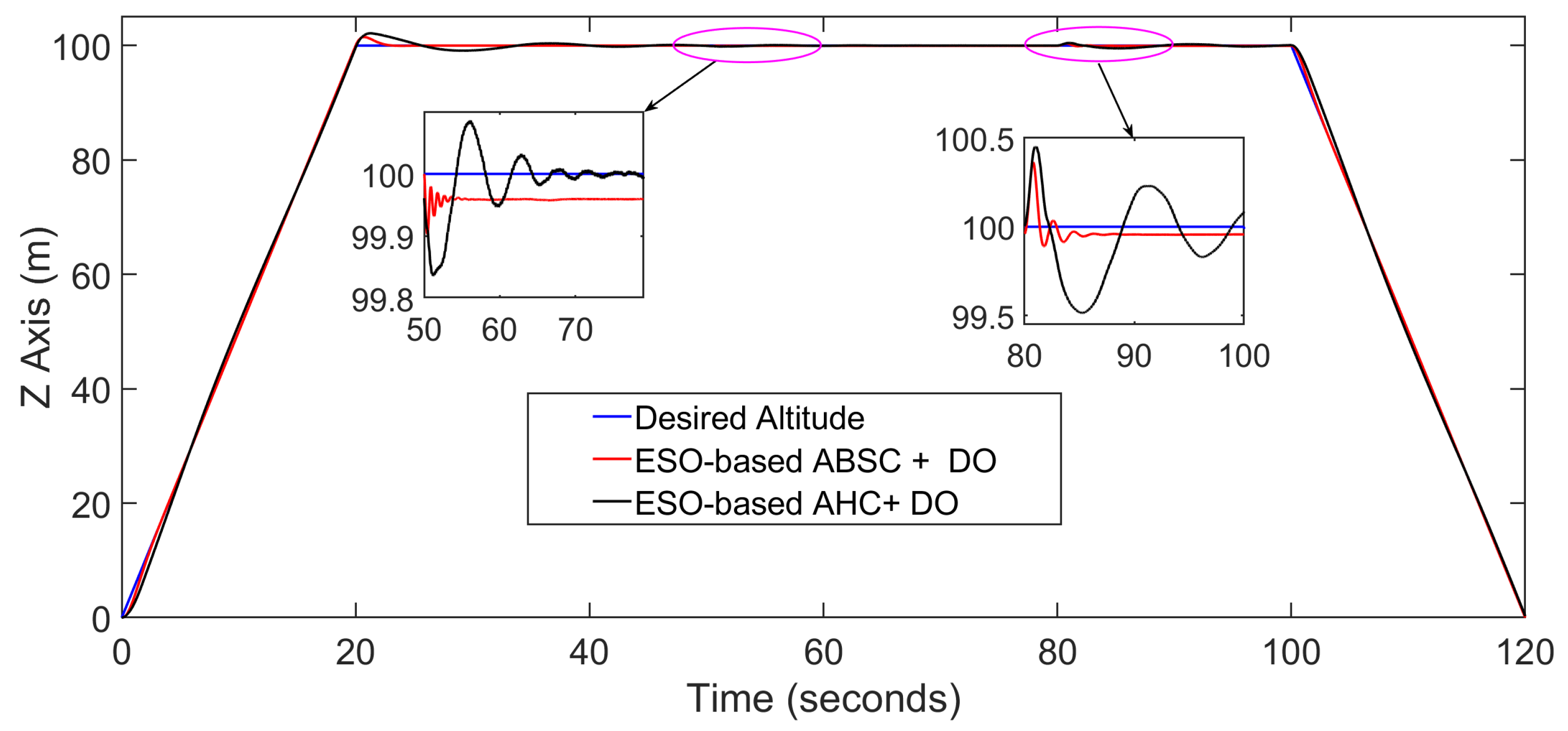
  • ESO-based ABSC + DO generates a steady-state error in the altitude, while ESO-based AHC with DO can track the altitude efficiently. A large overshoot is generated by the ESO-based ABSC + DO during the x axis trajectory tracking, and a steady-state error of 0.044 m is generated in the y axis trajectory tracking.
  • Dual observer-based adaptive hybrid controller tracks the desired altitude trajectory in the presence of the wind gust and mass change. The proposed control architecture is effective.

Author Contributions

Conceptualization, N.D. and D.D.; methodology, N.D. and D.D.; software, N.D.; validation, N.D. and D.D.; formal analysis, N.D., D.D. and S.O.; writing—original draft preparation, N.D. and D.D.; writing—review and editing, D.D. and S.O.; supervision, D.D.; funding acquisition, S.O. All authors have read and agreed to the published version of the manuscript.

Funding

This work was supported by the project SP2023/009, "Development of algorithms and systems for control, measurement and safety applications IX" of Student Grant System, VSB-TU Ostrava.

Data Availability Statement

Not applicable.

Conflicts of Interest

The authors declared no potential conflict of interest with respect to the research, authorship, and/or publication of this article.

References

  1. Oosedo, A.; Abiko, S.; Konno, A.; Koizumi, T.; Furui, T.; Uchiyama, M. Development of a quad rotor tail-sitter VTOL UAV without control surfaces and experimental verification. In Proceedings of the 2013 IEEE International Conference on Robotics and Automation, Karlsruhe, Germany, 6–10 May 2013; pp. 317–322. [Google Scholar]
  2. Oosedo, A.; Abiko, S.; Konno, A.; Uchiyama, M. Optimal transition from hovering to level-flight of a quadrotor tail-sitter UAV. Auton. Robot. 2016, 41, 1143–1159. [Google Scholar] [CrossRef]
  3. Hochstenbach, M.; Notteboom, C.; Theys, B.; Schutter, J. Design and Control of an Unmanned Aerial Vehicle for Autonomous Parcel Delivery with Transition from Vertical Take-off to Forward Flight–VertiKUL, a Quadcopter Tailsitter. Int. J. Micro Air Veh. 2015, 7, 395–406. [Google Scholar] [CrossRef] [Green Version]
  4. Swarnkar, S.; Parwana, H.; Kothari, M.; Abhishek, A. Biplane-Quadrotor Tail-Sitter UAV: Flight Dynamics and Control. J. Guid. Control Dyn. 2018, 41, 1049–1067. [Google Scholar] [CrossRef]
  5. Chipade, V.S.; Abhishek; Kothari, M.; Chaudhari, R.R. Systematic design methodology for development and flight testing of a variable pitch quadrotor biplane VTOL UAV for payload delivery. Mechatronics 2018, 55, 94–114. [Google Scholar] [CrossRef] [Green Version]
  6. Phillips, P.; Hrishikeshavan, V.; Rand, O.; Chopra, I. Design and development of a scaled quadrotor biplane with variable pitch proprotors for rapid payload delivery. In Proceedings of the American Helicopter Society 72nd Annual Forum, West Palm Beach, FL, USA, 17–19 May 2016; pp. 17–19. [Google Scholar]
  7. Yeo, D.; Hrishikeshavan, V.; Chopra, I. Gust detection and mitigation on a quad rotor biplane. In Proceedings of the AIAA Atmospheric Flight Mechanics Conference, San Diego, CA, USA, 4–8 January 2016; p. 1531. [Google Scholar]
  8. Ryseck, P.; Yeo, D.; Hrishikeshavan, V.; Chopra, I. Aerodynamic and mechanical design of a morphing winglet for a quadrotor biplane tail-sitter. In Proceedings of the Vertical Flight Society 8th Autonomous VTOL Symposium, Mesa, AZ, USA, 29–31 January 2019; pp. 29–31. [Google Scholar]
  9. Dalwadi, N.; Deb, D.; Kothari, M.; Ozana, S. Disturbance Observer-Based Backstepping Control of Tail-Sitter UAVs. Actuators 2021, 10, 119. [Google Scholar] [CrossRef]
  10. Dalwadi, N.; Deb, D.; Muyeen, S.M. Adaptive backstepping controller design of quadrotor biplane for payload delivery. IET Intell. Transp. Syst. 2022, 16, 1738–1752. [Google Scholar] [CrossRef]
  11. Dalwadi, N.; Deb, D.; Rath, J.J. Biplane Trajectory Tracking Using Hybrid Controller Based on Backstepping and Integral Terminal Sliding Mode Control. Drones 2022, 6, 58. [Google Scholar] [CrossRef]
  12. Dalwadi, N.; Deb, D.; Muyeen, S. Observer based rotor failure compensation for biplane quadrotor with slung load. Ain Shams Eng. J. 2022, 13, 101748. [Google Scholar] [CrossRef]
  13. Dalwadi, N.; Deb, D.; Ozana, S. Rotor Failure Compensation in a Biplane Quadrotor Based on Virtual Deflection. Drones 2022, 6, 176. [Google Scholar] [CrossRef]
  14. Ding, F.; Huang, J.; Wang, Y.; Zhang, J.; He, S. Sliding mode control with an extended disturbance observer for a class of underactuated system in cascaded form. Nonlinear Dyn. 2017, 90, 2571–2582. [Google Scholar] [CrossRef]
  15. Huang, J.; Ri, S.; Fukuda, T.; Wang, Y. A Disturbance Observer Based Sliding Mode Control for a Class of Underactuated Robotic System With Mismatched Uncertainties. IEEE Trans. Autom. Control 2019, 64, 2480–2487. [Google Scholar] [CrossRef]
  16. Rojsiraphisal, T.; Mobayen, S.; Asad, J.H.; Vu, M.T.; Chang, A.; Puangmalai, J. Fast Terminal Sliding Control of Underactuated Robotic Systems Based on Disturbance Observer with Experimental Validation. Mathematics 2021, 9, 1935. [Google Scholar] [CrossRef]
  17. Castillo, A.; Sanz, R.; Garcia, P.; Qiu, W.; Wang, H.; Xu, C. Disturbance observer-based quadrotor attitude tracking control for aggressive maneuvers. Control Eng. Pract. 2019, 82, 14–23. [Google Scholar] [CrossRef]
  18. Chen, A.J.; Sun, M.J.; Wang, Z.H.; Feng, N.Z.; Shen, Y. Attitude trajectory tracking of quadrotor UAV using super-twisting observer-based adaptive controller. Proc. Inst. Mech. Eng. Part G J. Aerosp. Eng. 2020, 235, 1146–1157. [Google Scholar] [CrossRef]
  19. Shin, D.; Song, Y.; Oh, J.; Oh, H. Nonlinear Disturbance Observer-Based Standoff Target Tracking for Small Fixed-Wing UAVs. Int. J. Aeronaut. Space Sci. 2020, 22, 108–119. [Google Scholar] [CrossRef]
  20. Dhaybi, M.; Daher, N. Accurate Real-time Estimation of the Inertia Tensor of Package Delivery Quadrotors. In Proceedings of the 2020 American Control Conference (ACC), Denver, CO, USA, 1–3 July 2020; IEEE: Piscataway, NJ, USA, 2020. [Google Scholar] [CrossRef]
  21. Boss, C.J.; Srivastava, V. A High-Gain Observer Approach to Robust Trajectory Estimation and Tracking for a Multi-rotor UAV. arXiv 2021, arXiv:2103.13429. [Google Scholar]
  22. Novella-Rodrìguez, D.F.; Witrant, E.; del Muro-Cuéllar, B.; Márquez-Rubio, J.F. Adaptive multi-observer design for systems with unknown long input delay. IFAC-PapersOnLine 2019, 52, 37–42. [Google Scholar] [CrossRef]
  23. Guo, K.; Jia, J.; Yu, X.; Guo, L.; Xie, L. Multiple observers based anti-disturbance control for a quadrotor UAV against payload and wind disturbances. Control Eng. Pract. 2020, 102, 104560. [Google Scholar] [CrossRef]
  24. Xingling, S.; Jun, L.; Honglun, W. Robust back-stepping output feedback trajectory tracking for quadrotors via extended state observer and sigmoid tracking differentiator. Mech. Syst. Signal Process. 2017, 104, 631–647. [Google Scholar] [CrossRef]
  25. Xuan-Mung, N.; Hong, S.K. Robust Backstepping Trajectory Tracking Control of a Quadrotor with Input Saturation via Extended State Observer. Appl. Sci. 2019, 9, 5184. [Google Scholar] [CrossRef]
  26. Wang, H.; Li, N.; Wang, Y.; Su, B. Backstepping Sliding Mode Trajectory Tracking via Extended State Observer for Quadrotors with Wind Disturbance. Int. J. Control Autom. Syst. 2021, 19, 3273–3284. [Google Scholar] [CrossRef]
  27. Dou, J.; Kong, X.; Wen, B. Altitude and attitude active disturbance rejection controller design of a quadrotor unmanned aerial vehicle. Proc. Inst. Mech. Eng. Part G J. Aerosp. Eng. 2016, 231, 1732–1745. [Google Scholar] [CrossRef]
  28. Xi, H.; Zhang, D.; Zhou, T.; Yang, Y.; Wei, Q. An Anti-wind Modeling Method of Quadrotor Aircraft and Cascade Controller Design Based on Improved Extended State Observer. Int. J. Control Autom. Syst. 2020, 19, 1363–1374. [Google Scholar] [CrossRef]
  29. Lien, Y.H.; Peng, C.C.; Chen, Y.H. Adaptive Observer-Based Fault Detection and Fault-Tolerant Control of Quadrotors under Rotor Failure Conditions. Appl. Sci. 2020, 10, 3503. [Google Scholar] [CrossRef]
  30. Lyu, X.; Zhou, J.; Gu, H.; Li, Z.; Shen, S.; Zhang, F. Disturbance Observer Based Hovering Control of Quadrotor Tail-Sitter VTOL UAVs Using H Synthesis. IEEE Robot. Autom. Lett. 2018, 3, 2910–2917. [Google Scholar] [CrossRef]
  31. Liu, H.; Peng, F.; Lewis, F.L.; Wan, Y. Robust Tracking Control for Tail-Sitters in Flight Mode Transitions. IEEE Trans. Aerosp. Electron. Syst. 2019, 55, 2023–2035. [Google Scholar] [CrossRef]
  32. Li, B.; Zhou, W.; Sun, J.; Wen, C.Y.; Chen, C.K. Development of Model Predictive Controller for a Tail-Sitter VTOL UAV in Hover Flight. Sensors 2018, 18, 2859. [Google Scholar] [CrossRef] [Green Version]
  33. Yang, H.; Cheng, L.; Xia, Y.; Yuan, Y. Active Disturbance Rejection Attitude Control for a Dual Closed-Loop Quadrotor Under Gust Wind. IEEE Trans. Control Syst. Technol. 2018, 26, 1400–1405. [Google Scholar] [CrossRef]
  34. Lungu, M. Backstepping and dynamic inversion combined controller for auto-landing of fixed wing UAVs. Aerosp. Sci. Technol. 2020, 96, 105526. [Google Scholar] [CrossRef]
  35. Zhou, L.; Xu, S.; Jin, H.; Jian, H. A hybrid robust adaptive control for a quadrotor UAV via mass observer and robust controller. Adv. Mech. Eng. 2021, 13, 168781402110027. [Google Scholar] [CrossRef]
  36. Liu, J.; Gai, W.; Zhang, J.; Li, Y. Nonlinear Adaptive Backstepping with ESO for the Quadrotor Trajectory Tracking Control in the Multiple Disturbances. Int. J. Control. Autom. Syst. 2019, 17, 2754–2768. [Google Scholar] [CrossRef]
  37. Mofid, O.; Mobayen, S.; Fekih, A. Adaptive Integral-Type Terminal Sliding Mode Control for Unmanned Aerial Vehicle Under Model Uncertainties and External Disturbances. IEEE Access 2021, 9, 53255–53265. [Google Scholar] [CrossRef]
  38. Navabi, M.; Davoodi, A.; Mirzaei, H. Trajectory tracking of under-actuated quadcopter using Lyapunov-based optimum adaptive controller. Proc. Inst. Mech. Eng. Part G J. Aerosp. Eng. 2022, 236, 202–215. [Google Scholar] [CrossRef]
  39. Torchani, B.; Sellami, A.; Garcia, G. Variable speed wind turbine control by discrete-time sliding mode approach. Isa Trans. 2016, 62, 81–86. [Google Scholar] [CrossRef]
  40. Labbadi, M.; Cherkaoui, M. Robust Integral Terminal Sliding Mode Control for Quadrotor UAV with External Disturbances. Int. J. Aerosp. Eng. 2019, 2019, 2016416. [Google Scholar] [CrossRef]
  41. Tatom, F.B.; Smith, S.R.; Fichtl, G.H.; Campbell, C.W. Simulation of atmospheric turbulent gusts and gust gradients. J. Aircr. 1982, 19, 264–271. [Google Scholar] [CrossRef]
Figure 1. Animated picture of biplane quadrotor.
Drones 07 00048 g001
Figure 2. Dual observer-based control architecture.
Drones 07 00048 g002
Figure 3. The Block Diagram of an adaptive hybrid controller.
Drones 07 00048 g003
Figure 4. Position subsystem tracking by ESO-based BSC with and without DO.
Drones 07 00048 g004
Figure 5. Position tracking by ESO-based ITSMC with and without DO.
Drones 07 00048 g005
Figure 6. Position tracking by different ESO-based controllers with DO.
Drones 07 00048 g006
Figure 7. Attitude tracking by different ESO-based controllers with DO.
Drones 07 00048 g007
Figure 8. x y position trajectory tracking by the ESO-based ABSC and AHC with DO.
Drones 07 00048 g008
Figure 9. Altitude tracking by the ESO-based ABSC and AHC and DO.
Drones 07 00048 g009
Figure 10. Attitude tracking by the ESO-based ABSC and AHC with DO.
Drones 07 00048 g010
Table 1. Simulation Parameters.
ParametersValue
g9.8 ms−2
Mass (m)12 kg
I x x 1.86 kg·m2
I y y 2.03 kg·m2
I z z 3.617 kg·m2
Disclaimer/Publisher’s Note: The statements, opinions and data contained in all publications are solely those of the individual author(s) and contributor(s) and not of MDPI and/or the editor(s). MDPI and/or the editor(s) disclaim responsibility for any injury to people or property resulting from any ideas, methods, instructions or products referred to in the content.

