Article

Lightweight Detection Network for Arbitrary-Oriented Vehicles in UAV Imagery via Global Attentive Relation and Multi-Path Fusion

College of Computer Science and Technology, Chongqing University of Posts and Telecommunications, Chongqing 400065, China
*
Author to whom correspondence should be addressed.
Drones 2022, 6(5), 108; https://doi.org/10.3390/drones6050108
Submission received: 13 March 2022 / Revised: 21 April 2022 / Accepted: 23 April 2022 / Published: 27 April 2022
(This article belongs to the Special Issue Advances in Deep Learning for Drones and Its Applications)

Abstract

:
Recent advances in unmanned aerial vehicles (UAVs) have increased altitude capability in road-traffic monitoring. However, state-of-the-art vehicle detection methods still lack accurate abilities and lightweight structures in the UAV platform due to the background uncertainties, scales, densities, shapes, and directions of objects resulting from the UAV imagery’s shooting angle. We propose a lightweight solution to detect arbitrary-oriented vehicles under uncertain backgrounds, varied resolutions, and illumination conditions. We first present a cross-stage partial bottleneck transformer (CSP BoT) module to exploit the global spatial relationship captured by multi-head self-attention, validating its implication in recessive dependencies. We then propose an angle classification prediction branch in the YOLO head network to detect arbitrarily oriented vehicles in UAV images and employ a circular smooth label (CSL) to reduce the classification loss. We further improve the multi-scale feature maps by combining the prediction head network with the adaptive spatial feature fusion block (ASFF-Head), which adapts the spatial variation of prediction uncertainties. Our method features a compact, lightweight design that automatically recognizes key geometric factors in the UAV images. It demonstrates superior performance under environmental changes while it is also easy to train and highly generalizable. This remarkable learning ability makes the proposed method applicable to geometric structure and uncertainty estimates. Extensive experiments on the UAV vehicle dataset UAV-ROD and remote sensing dataset UACS-AOD demonstrate the superiority and cost-effectiveness of the proposed method, making it practical for urban traffic and public security.

1. Introduction

Unmanned aerial vehicles (UAVs), also known as drones, are ideally suited for road-traffic monitoring and management because of their mobility, increased altitude capability, low cost, and broad view range [1]. Moreover, they avoid risks to pilots under difficult weather conditions and play a crucial role in managing transportation systems for next-generation intelligent cities [2]. Significantly, vehicle detection is a fundamental problem faced by these applications. Considerable progress is being made to create fully autonomous vehicle detection with UAVs. However, technical obstacles remain.
Efficient object detectors, for instance, play a crucial role in UAV applications and pose severe challenges due to numerous constraints, such as limited energy, speed, and vulnerability to various conditions. Recent approaches can be grouped by the orientation of the bounding box, such as horizontal detectors (horizontal bounding boxes) and rotation detectors (arbitrary-oriented bounding boxes). Previous studies on generic horizontal detectors can be divided into two categories: two-stage and one-stage detectors [3]. The two-stage detectors generate category-agnostic region proposals and then perform classification and regression on these candidate regions to classify and localize the targets, such as Faster R-CNN [4] and R-FCN [5]. Although two-stage detectors have high accuracy, they typically have slow speed and increased complexity. To achieve high efficiency, the developments of one-stage detectors perform bounding-box regression and classification simultaneously for improved inference speed and simplicity, such as SSD [6], YOLO series [7,8,9,10], and RetinaNet [11].
Although generic horizontal detectors have great success in natural scenes, a considerable performance drop is apparent when these detectors are directly used in UAV and aerial images. The poor performance is due to the specific nuisances of UAV images, such as complex backgrounds, significant differences in object sizes, and weather and illumination variations. Therefore, the improved generic horizontal detectors applied in UAV and aerial images have drawn increasing attention from researchers. Kim et al. [12] proposed an efficient channel attention pyramid YOLO (ECAP-YOLO) to detect small objects precisely in aerial images. Walambe et al. [13] combined different one-stage detector models and applied voting strategies to capture multi-scale objects in UAV images. Wu et al. [14] proposed a deep nuisance disentanglement approach, the nuisance disentangled feature transform (NDFT), to learn domain-robust features and improve the vehicle detection performance of generic-object detectors in UAV images. Yang et al. [15] proposed a clustered detection (ClusDet) network inspired by the often-clustered objects in some regions, which unifies object clustering and detection in an end-to-end framework. Vandersteegen et al. [16] focused on real-time object detection and tracking on limited hardware through an improved YOLOv3 model and a multi-dataset learning strategy. Li et al. [17] focused on the image-cropping strategy. They proposed a density map-guided object-detection network to address the challenge of the non-uniform distribution of objects in aerial images. The density map can judge whether there is an object in an area and help the network learn the scale information according to the pixel intensity, which can guide cropping images statistically. Koyun et al. [18] proposed a crop-based two-stage model to address the small-object detection problem in aerial images, mainly consisting of two parts. The first part is to generate clusters of objects through Gaussian Mixture, and the second part proposes the incomplete box suppression (IBS) algorithm to solve the incomplete boxes caused by overlapping focal regions.
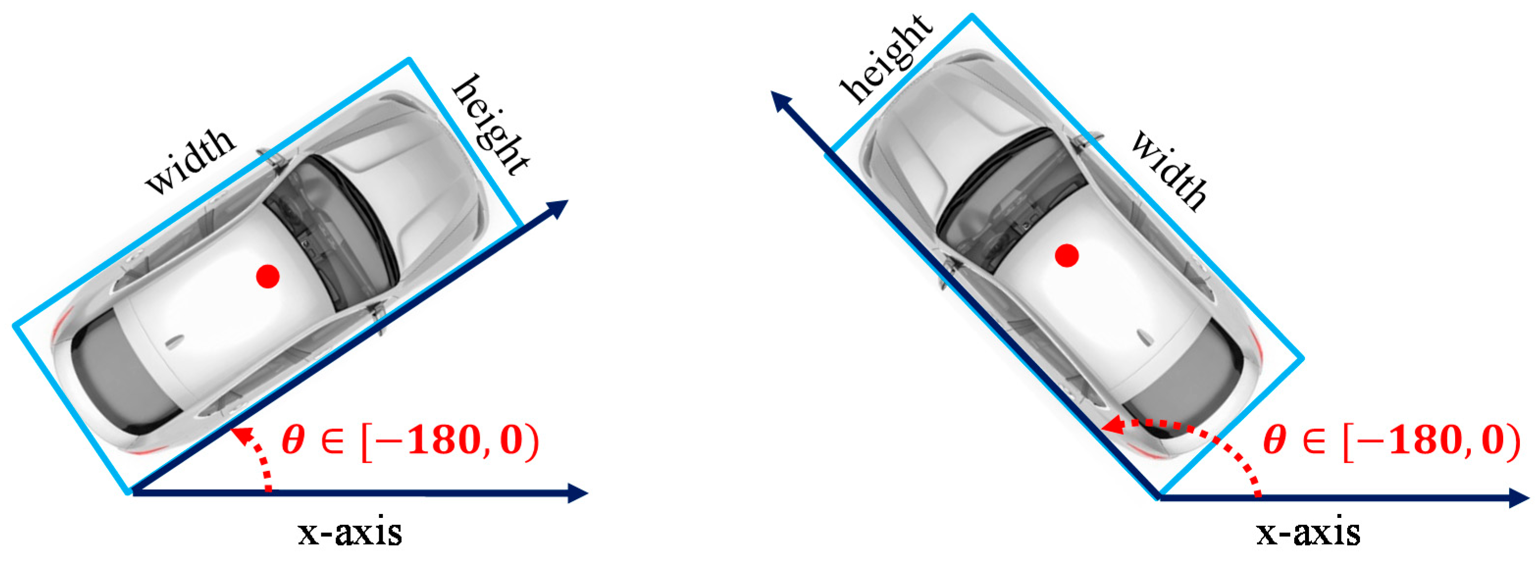
Most vehicles in UAV images have the characteristic of being arbitrary-oriented. The vehicle’s horizontal bounding box is less efficient when the vehicle orientation is not parallel to the coordinate axis from the drone’s perspective, as shown in Figure 1. There is a large empty margin and a false intersection area when vehicles are bounded with horizontal boxes, and it does not provide accurate rotation and scale information. Therefore, these horizontal detectors cannot be used in UAV platforms for vehicle detection if the view angle is the bird’s view. The rotated bounding box used to process rotating objects from UAV and aerial images can provide more accurate regions for instances and introduce considerably less background noise. Ma et al. [19] presented the extra orientation prediction and rotated anchor boxes into Faster RCNN to detect the oriented object. Yang et al. [20] designed a sampling fusion network to obtain a more effective anchor sampling and an improved smooth L1 loss by adding the IoU constant factor to address the boundary problem of rotated bounding-box regression. Ding et al. [21] applied a spatial transformation to transform the horizontal region of interest (ROI) into a rotated ROI. Yang et al. [
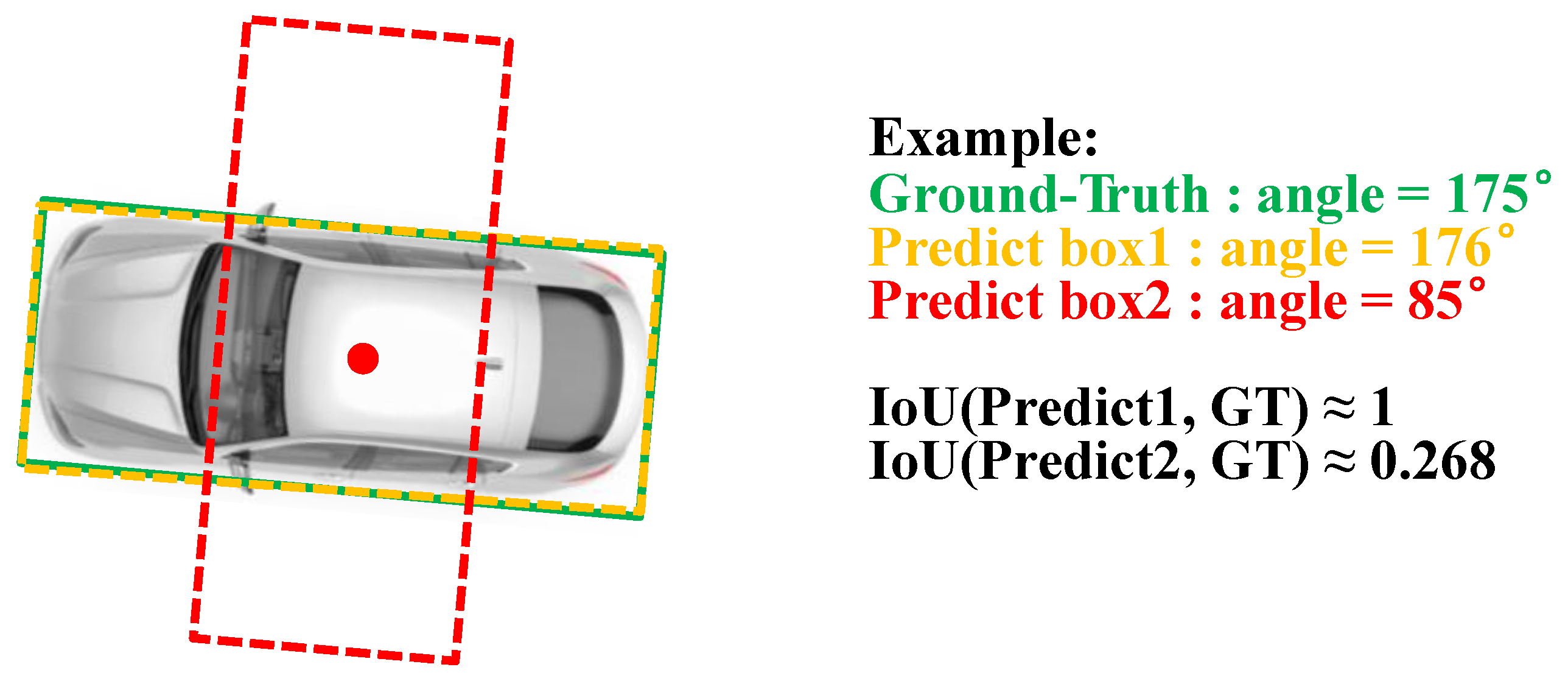
22] designed a circular smooth label (CSL) to convert angular prediction from a regression problem to a classification problem to avoid the discontinuous boundary problem. Based on this work, they further proposed a new angle-encoding mechanism, densely coded labels (DCL) [23], to speed up the angle classification branch. Ming et al. [24] proposed a critical feature capturing network (CFC-Net) to achieve superior detection performance through a polarized attention module and a dynamic anchor-selection strategy. Ming et al. [25] proposed a dynamic anchor-learning (DAL) method to alleviate the imbalance between positive and negative samples and the problem of feature misalignment between classification and regression tasks. Yi et al. [26] also regarded the angle prediction as a classification problem and captured the oriented bounding boxes through the box boundary-aware vectors (BBAVectors). Based on this work, Yu et al. [27] designed an anchor-free arbitrary-oriented object detector and introduced a context enhancement module to improve multi-feature information interaction. Ming et al. [28] constructed multiple representations of oriented targets and transformed the bounding-box regression task into an optimal matching process. In addition, Ming et al. [29] selected high-quality anchors to alleviate the imbalance between classification and regression tasks. Feng et al. [30] converted presented horizontal anchors into rotated anchors through anchor refinement in the RetinaNet algorithm. Despite the high-resolution UAV images, a lightweight model and real-time detection are required. These off-the-shelf arbitrary-oriented detection methods used in detecting vehicles still lack accurate, lightweight structure and real-time ability in the UAV platform.
Modeling the global units and their relations in an image is critical for arbitrary-oriented detection. The multi-head self-attention (MHSA) mechanism [31] has been shown to learn the relationship among distant targets effectively [32,33]. Moreover, the MHSA can facilitate handling nuisances in natural images [34], such as noise in the background and some occlusions. Therefore, several attention-based approaches have integrated the multi-head self-attention mechanism into their detector network [35,36,37]. Yu et al. [35] introduced a transformer module into the backbone network to enhance the detector performance in side-scan sonar images. Zhu et al. [36] applied transformer encoder blocks in the YOLO head network and the end of the backbone. Sun et al. [37] proposed an encoder-only DETR model to accelerate DETR training and improve the detector of FCOS and Faster RCNN based on it.
In addition to global relation capturing, computation-consuming and low storage capacity are essential for autonomous UAVs. Most rotation detectors build an intense and complex architecture of neural networks to achieve better accuracy. Thus, it brings up many more computations and storage burdens, making vehicle detection unaffordable for drones. The UAV platform’s key to accurate and real-time vehicle detection is finding a suitable base detection model that balances accuracy, model complexity, and inference speed. Furthermore, it should have a lightweight structure and be low-resource-intensive due to the UAV platform’s hardware computing power and storage-space limitation. Several efforts have been made to perform light-object detection. For instance, YOLOv5 [38] is the SOTA, the most notable and convenient one-stage detector with fast detection speed and precision, including YOLOv5s, YOLOv5m, YOLOv5l, YOLOv5x. YOLOv5x can obtain 68.9% AP@0.5 for the COCO val2017 dataset, and the minimum model size of the YOLOv5s is only 14 megabytes. Considering the accuracy and model complexity, we selected YOLOv5s as our base model for the UAV dataset UAV-ROD [30] and YOLOv5m for the remote-sensing dataset UCAS-AOD [
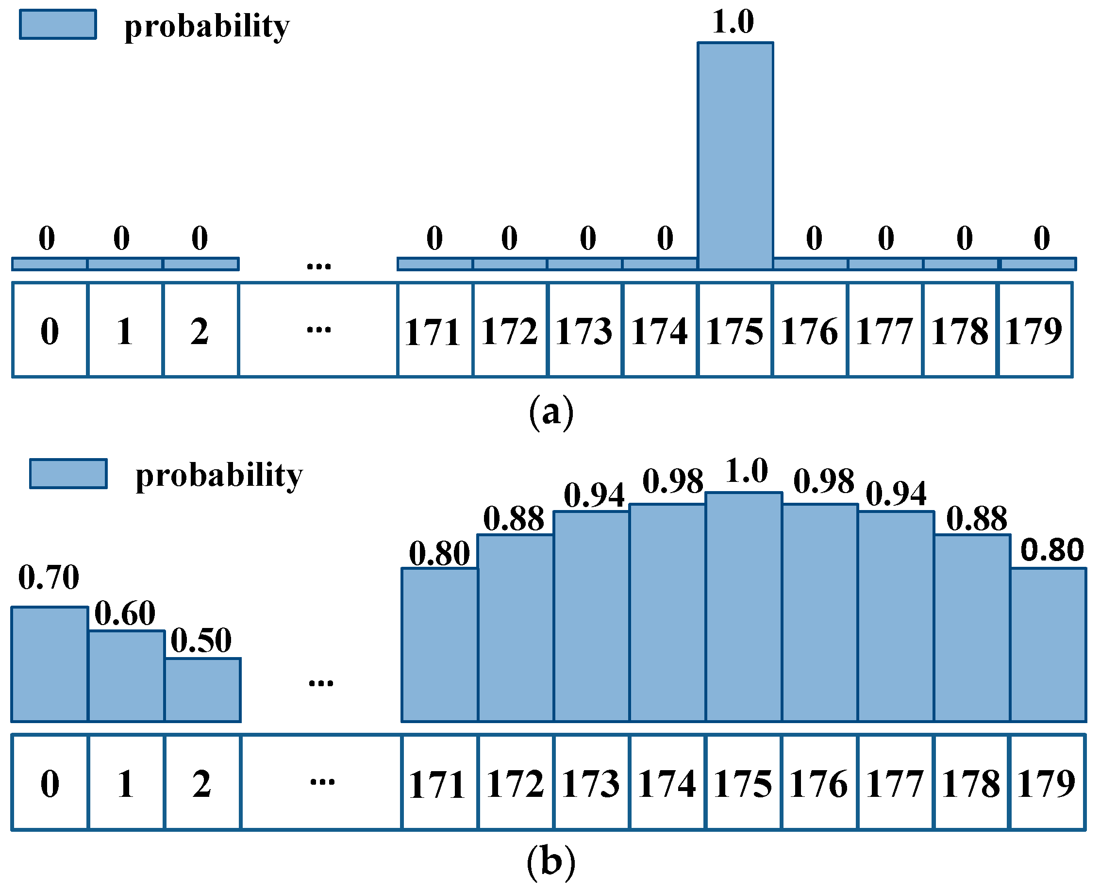
39]. However, YOLOv5 is a generic horizontal detector that is not fully applicable to UAV images. The horizontal bounding box for the vehicles is less efficient when the view angle of the UAV is bird-view. In contrast, we added an angle classification prediction branch in the YOLO head network and employed the circular smooth label to avoid the discontinuous boundary problem and reduce the classification loss.
While aiming for a cost-effective and scalable detection model for arbitrary-oriented vehicles in UAV Imagery, three serious challenges need to be addressed: (1) Efficiency. Current methods for arbitrary-oriented detection require a significant amount of computation and storage, making them impractical for time-critical applications. (2) Adaptivity. The UAV can fly at various altitudes while capturing images from different and complementary angles, which causes significant differences in target sizes and more different visual appearances of the same object. However, most works lack adaptivity, and they do not allow scale or angle differences that may require resampling to be considered. (3) Correlativity. Vehicles are distributed on the road randomly according to a Poisson distribution and tend to be highly clustered in certain regions, such as parking lots. However, most detectors do not consider the distribution characteristics of vehicles.
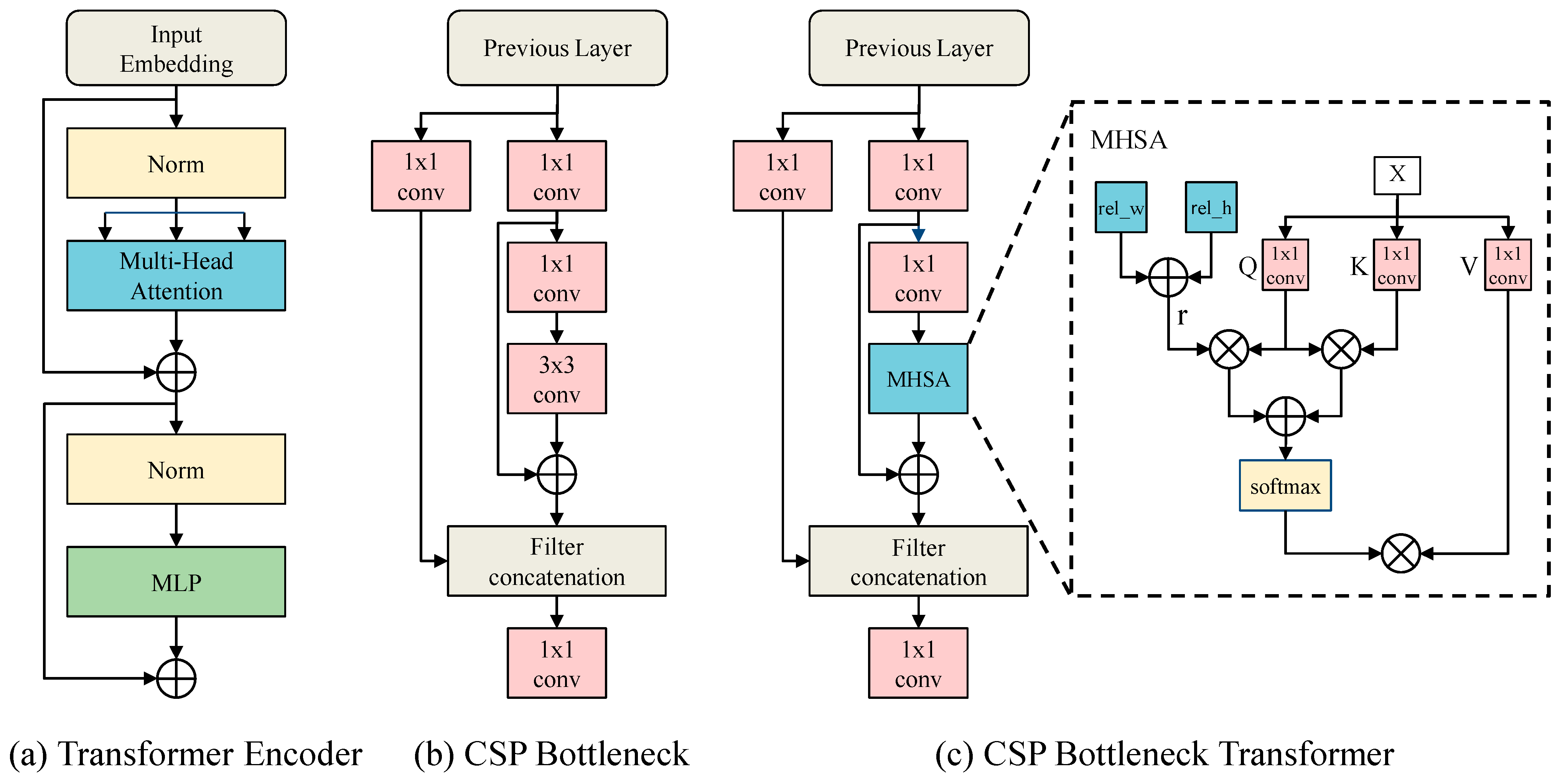
This paper addresses the above problems in a lightweight structure with global attentive relations and multi-path fusion. First, we developed a cross-stage partial bottleneck transformer (CSP BoT) module to capture vehicles’ potential global spatial relationships in UAV images and enhance the critical information. By replacing some blocks in YOLOv5 with the CSP BoT, it follows that detection tasks can capture vehicles’ potential global spatial relationships, thus enabling multi-scale insensitivity to uncertainties. Second, we proposed the multi-scale feature fusion by combining the prediction head network with the adaptive spatial feature fusion (ASFF) block [40], which can autonomously learn the spatial weights of different feature maps and improve their interaction. Thus, it captures more detailed features, enabling global spatial correlation analysis. Furthermore, our approach, composed of simple but effective modules, balances model size and accuracy well. The experimental results validate its excellent performance in detecting arbitrary-oriented vehicles.
In summary, the main contributions of this article are summarized as follows:
  • We proposed a lightweight arbitrary-oriented vehicle detection network. We incorporated an angular classification prediction branch in the YOLO head network and employed a circular smooth label to reduce the classification loss. This significantly improves the detection performance for arbitrary-oriented vehicles in UAV images without incurring the extra model complexity and computation burden.
  • We presented a cross-stage partial bottleneck transformer (CSP BoT) module to our detection framework, a hybrid module using convolutions and the multi-head self-attention mechanism that can capture vehicles’ potential global spatial relationship in UAV images and enhance critical information.
  • Considering the specific characteristics of UAV images, such as complex backgrounds, different visual appearances of the same object, and significant variations in target sizes, we combined the adaptive spatial feature fusion (ASFF) block with the prediction head (ASFF-Head). This adaptively combines features of different resolutions before prediction to improve the multi-scale feature fusion and enhance information interaction.
  • Extensive experimental results on the UAV vehicle dataset UAV-ROD and remote sensing dataset UACS-AOD show the proposed method’s superiority, cost-effectiveness, and low model complexity.

2. Materials and Methods

This section introduces the proposed network of arbitrary-oriented vehicle detection and several specific improvement measures, including cross-stage partial bottleneck transformer (CSP BoT), adaptive spatial feature fusion prediction head (ASFF-Head), and improved multi-task loss function.

2.1. Overview of the Proposed Model

The overall structure of our proposed network is illustrated in Figure 2. It is improved based on the detection network of YOLOv5s, and it can be divided into three parts: backbone, neck, and prediction. The backbone network is fine-tuned based on the YOLOv5s, and we replaced the C3 module after the spatial pyramid pooling (SPP) [41] structure with CSP BoT to make it more suitable for vehicle detection in UAV images. The neck is designed to better use the feature maps by collecting feature maps from different stages in the backbone. Our neck is a combination structure of a feature pyramid network (FPN) [42] and a path aggregation network (PANet) [43], and we replaced the first C3 module in the bottom-up path with CSP BoT. The prediction was used to generate the vehicle’s classification, position, objectness, and angle information in UAV images.
We first performed data augmentation to enhance the UAV images, including random flip, HSV augmentation, translation, and rotation. Then we sent the preprocessed images to the backbone network to extract general features. The backbone network consists of several different modules. The Focus module takes out every other pixel on the three RGB channels of an input image, as shown in Figure 2. It halves the height and width but expands its channel four times, transferring the spatial information to the channel dimension. The Conv block contains a convolution layer, batch normalization layer, and a sigmoid-weighted linear unit [44] activation function. The SPP module mainly contains three maxpool layers, improving multiple receptive fields fusion and the detection performance for small targets. The C3 module is short for CSP Bottleneck. The C3 module and CSP BoT are described in Figure 3. Next, the PANet and FPN structures transmit the low-level feature information to the high-level feature maps through bottom-up paths, and high-level semantic information is sent to the bottom feature maps through top-down approaches. Subsequently, the ASFF-Head module enhances the information interaction before prediction and performs different operations depending on a different phase. The ASFF-Head computes multi-task loss during the training phase, including classification loss, horizontal bounding-box regression loss, confidence loss, and angle loss. The testing phase generates detection predictions via non-maximum suppression (NMS).

2.2. CSP Bottleneck Transformer (CSP BoT) Module

From the UAV dataset UAV-ROD, we observed that vehicles are only distributed in specific image areas and tend to be highly clustered in certain regions, such as roads and parking lots. In their high-level features, some feature pixels represent the vehicle information, some represent important environmental information related to these vehicles, such as roads, etc., and some are insignificant. Using the MHSA mechanism in these feature maps, we can calculate the relationship among different pixels to capture this potential global spatial relationship and enhance critical information.
The most widely used MHSA mechanism structure is the transformer encoder [45], as shown in Figure 3a. It mainly contains two layers. The first layer is the MHSA and the second layer is the multi-layer perceptron (MLP) model. Some recent studies applied it in their YOLOv5 network and improved detection performance [35,36]. The cross-stage partial network (CSPNet) architecture can optimize gradient combinations while reducing the computation cost [46]. As CSPNet was proposed, the CSP Bottleneck designed based on the CSPNet structure has been the basic component of YOLOv4 and YOLOv5, as shown in Figure 3b. It divides the input feature map into two parts and combines them through a cross-stage residual edge. Motivated by this and MHSA in BotNet [47], we propose a cross-stage partial bottleneck transformer (CSP BoT) module by integrating MHSA into CSP Bottleneck, as shown in Figure 3c.
CSP BoT is a hybrid model using convolutions and MHSA. The MHSA is the core component and introduces three 1 × 1 convolutions to compute Q, K, V, and the relative position parameters. The vector Q h ,   K h , and V h are given as:
Q h = XW h q ,   K h   = XW h k ,   V h   = XW h v ,
where W h q ,   W h k , and W h v are learned linear transformations from input matrix X to queries Q, keys K, and values V of head h. Considering the two-dimensional positional embeddings of the self-attention mechanism [48], this output of head h can be formulated as:
O h = Softmax ( Q h K h T + S h H + S h W d k h ) V h
where S h H , S h W   R HW × HW are matrices of relative position logits along the height and width dimensions, and d k h is the dimension of keys in head h. The relative position matrix S h H [ i , j ] and S h W [ i , j ] are given as:
S h H [ i ,   j ] = q i T r j y i y H
S h W [ i ,   j ] = q i T r j x i x W
where q i is the i-th row of queries Q and r j y i y H and r j x i x W are learned relative positional embeddings for height and width, respectively.
We only apply CSP BoT at the end of the backbone network and the start of PANet. Because these two feature maps are low-resolution and contain more semantic information, using CSP BoT can capture global information and much contextual information without expensive computing and storage overhead.
Compared with the structure of the transformer encoder, the CSP BoT model is lighter and has lower computational complexity. Furthermore, the ablation study in the UAV-ROD dataset proves the superiority of using CSP BoT in our detection framework rather than transformer encoder and CSP Bottleneck.

2.3. ASFF-Head

Drones are very flexible when shooting images, which will cause the scale of the vehicle target in the image to vary significantly. Unlike surveillance cameras that only capture images of a specific area, drones usually capture a more extensive range. The background of these images is complex and constantly changing, which introduces considerable background noise. Therefore, the vehicle detection network requires a powerful feature-fusion module.
The structure combination of PANet and FPN consists of a bottom-up path and a top-down path, an effective multi-scale feature fusion method. However, it suffers from the inconsistency of target scales at different feature layers. Before prediction, it cannot fully utilize varying feature branch information, limiting the information interaction in the feature maps and further performance gain. To solve this problem, ASFF-Head is introduced in this paper. The ASFF module can filter features at three levels after neck and combine the helpful information. We combined the YOLOv5 head network with the ASFF. The target of ASFF-Head autonomously learns the spatial weights of each scale and then fuses them to generate feature maps of homogeneous sizes before prediction. The structure is shown in Figure 4, and it consists of three steps: (1) scale transformation, (2) adaptive fusion, and (3) prediction.

2.3.1. Scale Transformation

The resolution and channel of the three feature maps F1F2F3 obtained through the neck are different, and their resolutions are 1/8, 1/16, and 1/32 of the original image, respectively. Therefore, we first need to harmonize their resolutions and channels before adaptive fusion by taking up-sampling or down-sampling strategies and 1 × 1 convolutions. Specifically, for up-sampling, we first applied 1 × 1 convolutions to harmonize the number of channels of feature maps to that in level l and then upscaled the resolution through interpolation. For down-sampling with a 1/2 ratio, we used 3 × 3 convolutions with a stride of 2 to modify the number of channels and the resolution simultaneously. For down-sampling with a 1/4 ratio, we added a two-stride-max-pooling layer first and then employed 3 × 3 convolutions with a stride of 2.

2.3.2. Adaptive Fusion

As shown in Figure 4, taking ASFF-Head2 as an example. If the feature map F2 after fusion is marked as L2, three spatial weights of F1, F2, F3 to L2 are marked as α 2 , β 2 , γ 2 , respectively. It is expressed as the following formula:
L ij 2 = α ij 2 · F ij 1 2   + β ij 2 · F ij 2 2 + γ ij 2 · F ij 3 2
where F ij 1 2 and F ij 3 2 represent the processed result of scale transformation, converting the feature vector at position (i, j) in F1 and F3 to the same resolution and channel as F2. It is noted that α ij 2 , β ij 2 and γ ij 2 are scalar variables and are defined as follows by using the softmax function:
α ij 2 = e λ α ij 2 e λ α ij 2 + e λ β ij 2 + e λ γ ij 2
β ij 2 = e λ β ij 2 e λ α ij 2 + e λ β ij 2 + e λ γ ij 2
γ ij 2 = e λ γ ij 2 e λ α ij 2 + e λ β ij 2 + e λ γ ij 2
where force α ij 2 + β ij 2 + γ ij 2 = 1 and α ij 2 ,   β ij 2 ,   γ ij 2   [ 0 ,   1 ] . λ α ij 2 ,   λ β ij 2 and λ γ ij 2 are the control parameters of three weights, respectively. We use 1 × 1 convolutions to compute them, and they can thus be learned through standard back-propagation.

2.3.3. Prediction

After subjecting the feature maps from neck to scale transformation and adaptively spatial feature fusion, we integrated the feature information and transformed it into the prediction. Our multi-scale detection head will generate the corresponding scale prediction feature maps and output detection results for large, medium, and small targets, respectively, according to different feature branches. Specifically, the prediction feature map from F1 is suitable for detecting small vehicles, such as small cars. The prediction feature map from F2 is ideal for detecting medium vehicles, such as trucks and vans. The prediction feature map from F3 is suitable for detecting large vehicles, such as buses.
There are three preset anchor boxes of corresponding scales of each grid from the prediction feature map. Each grid will generate (K + 4 + 1 + 180) prediction parameters. K represents the number of the target class; 4 represents the center point coordinates and the offset of the width and height; 1 represents the object’s confidence; 180 represents the 180 classification angles. During the training phase, we used these parameters to compute the multi-task loss. In addition, we leveraged the non-maximum suppression algorithm during the testing phase to process the results and obtain the final prediction results.

2.4. Multi-Task Loss Function

In the rotated bounding box, the boundary is not parallel to the coordinates axis. Therefore, we cannot adopt the definition of w and h of the horizontal bounding box. In this study, the five-parameter method was used to define the rotated bounding box, as shown in Figure 5. The longer side is defined as w and the short side as h, and the angle between the width and the x-axis is the rotation angle. The range of the rotation angle is [−180, 0). In order to facilitate network training, the angle of each target in the label is added by 180 degrees. Therefore, the range of the target angle in the label is [0,180).
For our arbitrary-oriented vehicle detection network, we added an angular classification layer to the YOLOv5 prediction head and decoupled the angle information from the bounding box regression parameters. Therefore, the total loss is given as:
L total = λ 1 L ang + λ 2 L reg + λ 3 L obj + λ 4 L cls
where L ang ,   L reg , L obj , and L cls represent the angle loss, horizontal bounding box regression loss, confidence loss, and classification loss, respectively. The λ 1 , λ 2 , λ 3 , and λ 4 are hyper-parameter to control the loss weight.

2.4.1. Angle Loss

Most rotation detectors obtain angle information through region regression, but these detectors have their limitations. The regression methods will suffer the problem of discontinuous boundaries and usually require additional and more complex treatment to alleviate the problem [22], which increases the complexity of the detector. Meanwhile, the vehicle in UAV images occupies more pixels and has a smaller aspect ratio than the target in the remote-sensing images, which means the vehicle in the UAV image has a relatively high tolerance to the angle prediction. As shown in Figure 6, the vehicle angle label is 175°, but a rotated bounding box with an angle of 176° can also provide an accurate region. Therefore, we transformed the angular prediction from a regression problem to a classification problem to avoid the discontinuous boundary problem and simplify the angle-prediction algorithm. Although converting from continuous regression to discrete classification can cause certain losses, the loss of accuracy has a negligible impact on the vehicle detection task with a high tolerance between adjacent angles.
As the five-parameter representation method has a 180° angular range, we divided the angles into 180 classes with a 1° interval between each angle class. However, the vanilla classification loss cannot measure the effect of the rotation angle distance between the predicted rotated bounding box and the ground truth on the IoU calculation. As shown in Figure 6, the angle prediction results are 176° and 85°, respectively. Their angle losses are the same when the one-hot label codes the angled label, but the prediction result of the angle equal to 176° close to the ground-truth should be allowed from the IoU calculation and the detection visualization. Meanwhile, the one-hot label suffers the problem of angular class imbalance. Therefore, we used the circular smooth label (CSL) to code the angle ground-truth before calculating angle classification loss.
CSL converts the original angle label into 180 labels with a window function. The comparison of the CSL and the one-hot label is shown in Figure 7. The CSL has a high error tolerance for adjacent angles and alleviates the problem of angle-class imbalance compared with the one-hot label. It can obtain a more robust angular prediction. The expression of CSL is as follows:
CSL ( x ) = { g ( x ) ,   θ r   <   x   <   θ + r 0 ,   otherwise
where g ( x ) is a window function with four properties: periodicity, symmetry, maximum, and monotonic. The most effective window function is the Gaussian function [22]. The expression is as follows:
g ( x ) = exp ( ( x θ ) 2 2 r 2 )
where θ represents the ground truth of the angle and r represents the window radius. The window radius controls the error tolerance between adjacent angles. The angle loss is calculated with binary cross-entropy (BCE) logit loss as follows:
L Ang = i N p BCEWithLogits ( P ang ,   CSL ( θ ) )
where N p indicates the number of prediction layers. P ang and CSL ( θ ) denote the prediction of the angle and angle labels encoded by CSL, respectively. BCEWithLogits is defined as
L BCEWithLogits   = n = 1 N [ y i · log σ ( x i ) + ( 1 y i ) · log ( 1 σ ( x i ) ) ]
where N represents the number of the input vector, x i and y i represent the predicted vector and ground-truth vector, respectively.

2.4.2. Horizontal Bounding-Box Regression Loss

IoU, GIoU, DIoU, and CIoU are mainly used to calculate the bounding-box regression loss in the horizontal-object detection task [49]. However, these algorithms will not be suitable for calculating IoU between rotating rectangular boxes when the angle is obtained through a regression algorithm for the arbitrary-oriented detection task. Our model adopts the CSL algorithm to solve the problem of angle prediction. It processes the angle prediction into a classification task and decouples the angle information from the bounding-box regression parameters. Therefore, the rotating bounding-box regression loss is divided into the angle and horizontal bounding-box regression losses. The latter still uses the IoU, GIoU, DIoU or CIoU loss function.
An excellent horizontal bounding box regression loss should consider three geometric factors: overlap area, center point distance, and aspect ratio. Therefore, the CIoU loss is adopted for L reg , which is calculated as:
L reg = i N p L CIoU
L CIoU = 1 IoU + ρ 2 ( b ,   b gt ) c 2 + α υ
where IoU is defined as the ratio of the intersection and union of the areas between the predicted bounding box and the ground-truth box. The b and b gt represent the center points of the two boxes, respectively. The ρ represents the Euclidean distance between the two center points. The c is the diagonal length of the smallest enclosing box covering two boxes. The υ measures the consistency of the aspect ratio and is given as follows:
υ = 4 π 2 ( artan   w gt h gt artan   w h ) 2
where w and h represent the width and height, respectively. α is a positive trade-off parameter. It is defined as
α = υ ( 1 IoU ) + υ

2.4.3. Confidence Loss and Classification Loss

The binary cross-entropy (BCE) logits loss is also adopted to calculate the confidence loss and classification loss, which is given as:
L obj = i N p BCEWithLogits ( P obj ,   T obj )
L cls = i N p BCEWithLogits ( P cls ,   T cls )
where P obj indicates the predicted confidence, and T obj indicates the CIoU between the predicted bounding box and the ground-truth box. P cls represents the predicted probability distribution of all classes, and T cls is the corresponding probability distribution of the ground truth.
It is noted that the correlation between the prediction confidence and the prediction angle is completely decoupled, which means the confidence loss is only related to the horizontal bounding-box regression parameters.

3. Experiments and Discussion

3.1. Datasets and Implementation Details

3.1.1. UAV-ROD

The UAV-ROD dataset is a low-altitude, drone-based dataset with a flying height between 30 m and 80 m, including 1577 images and 30,090 vehicle instances annotated by oriented bounding box labels. The original images are sampled into two resolutions: 1920 × 1080 and 2720 × 1530. The image scenes are rich and diverse, including urban roads, parking lots, residential areas, roadsides, etc. The total dataset is divided into the training and test sets, including 1150 and 427 images.

3.1.2. UCAS-AOD

UCAS-AOD is a high-resolution aerial-object detection dataset, including two categories of cars and airplanes. It is collected from Google Earth and contains 1510 images, including 1000 images for planes and 510 images for cars annotated by the oriented bounding box. Following the division method of images by Ming et al. [24], the total dataset is divided into the training set, validation set, and test set with 755 images, 302 images, and 452 images, respectively.

3.1.3. Implementation Details

Experiments were conducted using Python programming based on the Pytorch 1.7 deep-learning framework. The experimental training and validating environment was the Ubuntn16.04 system, running on an Intel CPU Xeon Gold 6126, NVIDIA Tesla V100, 256 GB RAM. The experimental testing environment was the Ubuntu 18.04 system, running on an Intel i5-9400F CPU@2.90GHz, with an NVIDIA GeForce RTX 2060.
For the UAV-ROD dataset, we used stochastic gradient descent (SGD) with momentum as the training optimizer, setting the initial learning rate to 0.01 and momentum and weight decay coefficients to 0.937 and 0.0005, respectively. The batch size was set to 16 in the evaluation of angular classification and 8 in other ablation studies. The epoch was set to 200. The Adam optimizer was used for training for the UCAS-ROD dataset, and the learning rate was set to 0.001. The batch size was set to 4, and the epoch was set to 200. The confidence threshold was set to 0.4, and the IoU threshold was set to 0.2 in all experiments during the test.
Owing to the high resolution of UAV images and remote sensing images and the limitation of the hardware device, we needed to preprocess the original image. Directly processing the high-resolution images will increase the computational burden and significantly reduce the training effectiveness. Therefore, we uniformly resized and padded the image to 960 × 960 for the UAV-ROD dataset and 800 × 800 for the UCAS-AOD dataset. In all ablation study experiments, we only shuffled the training images and did not employ any data augmentation to ensure the consistency of the training data. The number in bold of all tables denotes the best result in all tables.

3.2. Ablation Study

3.2.1. Evaluation of All Modules

We conducted a series of experiments on the UAV-ROD dataset to demonstrate the superiority of all modules. We used the original YOLOv5s as the baseline model and added a YOLOv5m-CSL model as the comparative model. The experimental results are shown in Table 1.
The CSL angle encoding strategy significantly improved the detection results, increasing 54.03% in AP and 55.95% in AP50. It indicates that the original YOLOv5s cannot learn the angle information of the rotated bounding box in vehicles, and the YOLOv5s with the CSL can obtain the angle information of vehicle targets accurately. Meanwhile, the CSL almost does not incur additional model complexity and computation burden. It only adds extra angle-prediction parameters in the prediction head network. The CSP BoT captures the potential global spatial relationship in high-level feature maps and enhances critical information, and reduces the parameters and model size by replacing 3 × 3 convolutions with MHSA in CSP Bottleneck. As a result, the CSP BoT improved AP by 8.61% and AP50 by 5.33%, while parameters were reduced by 0.36 million and model size was reduced by 0.7 MB. Meanwhile, the YOLOv5s-CSL with CSP BoT detection result in AP50 is better than YOLOv5m-CSL, while its parameters and model size are nearly three times smaller than the latter. The ASFF-Head further improves the AP by 1.68% and AP50 by 0.83%. It proves that adaptive spatial-feature fusion can further multi-feature information interaction and enhance the detection performance. Although the ASFF-Head increases the parameters and model size, the YOLOv5s-CSL with CSP BoT and ASFF-Head parameters and model size are half of the model YOLOv5m-CSL, and its detection performance in AP and AP50 are better than the latter.

3.2.2. Evaluation of Angular Classification

The accuracy of the CSL-improved YOLOv5s depends to a large extent on the Gaussian window radius. The circular smooth label tends to be a one-hot label when the window radius is too small. The larger the window radius, the bigger is the deviation of the angle prediction, and the smaller the window radius, the harder it is for the model to learn angle information. Therefore, a different application scenario has a different suitable window radius. As shown in Table 2, the most appropriate window radius in the UAV-ROD dataset is 12 after a series of experiments. However, the value is 6 in the remote-sensing dataset UCAS-AOD dataset, as shown in Table 3.
For vehicles in UAV images, the window radius tends to be large because the minor deviations in angle prediction have little effect on the rotated bounding box of vehicles. A big window radius can significantly alleviate the problem of angle-class imbalance. For rotating-object detection in remote-sensing images, the window radius is often set to be relatively small. The target in remote-sensing images tends to be small and occupies fewer pixels than the target in UAV images. Therefore, it is more sensitive to angles because the minor deviations in angle information can cause a significant effect on the rotated bounding box.

3.2.3. Evaluation of CSP BoT

In this section, we compare the performance of the CSP Bottleneck and different multi-head self-attention modules, including CSP BoT and transformer encoder. The original YOLOv5 model uses CSP Bottleneck at the end of the backbone and the start of the PANet. We replaced it with a transformer encoder or CSP BoT, and the comparison of the results of the various models is shown in Table 4. The model parameters, floating-point operations (FLOPs), and model size describe the model complexity. GFLOPs denote 1 billion FLOPs. Meanwhile, we added a YOLOv5m-CSL model as our other comparative model. Its model size is almost three times that of YOLOv5s-CSL. Naturally, it can also achieve better AP50.
According to the test results, we can see that the transformer encoder and CSP BoT can not only increase AP50 but also reduce the model size, parameters, and GFLOPs to some extent. This also proves that the multi-head self-attention mechanism is helpful in vehicle detection in UAV images. Specifically, after using the transformer encoder, the AP50 increases from 90.37% to 94.25%, and GFLOPs decrease from 17.9 to 17.5. Furthermore, the use of the proposed module CSP BoT increases the AP50 from 90.37% to 95.70%, decreases the total parameters from 7.54 to 7.18 and GFLOPs from 17.9 to 17.3. Significantly, its detection performance in AP50 is better than the big model YOLOv5m-CSL, and the latter has nearly three times the model size and parameters.
Compared with the original CSP Bottleneck in YOLOv5, the CSP Bottleneck is a fully convolutional model. The CSP BoT is a hybrid model using convolutions and the multi-head self-attention mechanism, which can change the weightings of each pixel in feature maps based on the global attention from several subspaces and focus on targets and the significant area near the targets, not the background noise. The original CSP Bottleneck in YOLOv5 uses 3 × 3 convolution at the MHSA in the CSP BoT. The 3 × 3 convolution only focuses on a small and fixed receptive field, but MHSA considers the global and effective information via flexible and dynamic receptive fields to encode contextual cues. Therefore, the model incorporating the MHSA mechanism, including the transformer encoder and CSP BoT, can improve detection accuracy significantly compared to the original CNN model in this task. Moreover, the 3 × 3 convolution introduces more parameters and extra floating-point operations compared to the MHSA structure in CSP BoT. It is noted that the MHSA-related models require more GPU memory, training, and inference time as the self-attention mechanism is the quadratic time and memory complexity with input sequence length [50].
Compared with the transformer encoder, the CSP BoT can perform better while reducing parameters, GFLOPs, and model size. The transformer encoder improves AP by 3.88% by replacing the CSP Bottleneck, but the CSP BoT improves by 5.33% in the same way. Additionally, the parameters, GFLOPs, and model size of the CSP BoT are smaller than the transformer encoder. The MHSA plays a crucial role in both models, but the architecture of CSPNet is more suitable for the framework of YOLOv5 as the structure of CSP has been the basic structure of YOLOv4 and YOLOv5 since it was proposed.

3.2.4. Evaluation of ASFF-Head

The ablation study on ASFF-Head is shown in Table 5. We also added a YOLOv5m-CSL model as our other comparative model. Our ASFF-Head achieves a remarkable improvement of 9.67% in AP and 5.47% in AP50, which indicates that ASFF-Head can further fuse the multi-level feature maps and help the detector accurately localize the rotating vehicles that vary significantly in size. Although it increases the complexity and size of the original model, its model size and complexity are half of the model YOLOv5m-CSL, and its detection performance AP and AP50 are better than the latter.

3.3. Comparisons with State-of-the-Arts

3.3.1. Results on UAV-ROD

The UAV-ROD dataset has only one category of vehicles, where some of them have various orientations, significant differences in size, and intensive distribution. Therefore, it is still challenging to accurately detect vehicles in this UAV dataset, especially high-quality detection performance. Table 6 shows the comparison of different methods on the UAV-ROD dataset in terms of the AP, AP50, number of parameters, model size, and FPS. Following the MS COCO evaluation metrics, we report the AP and AP50 results. Our method achieves the best detection accuracy in AP of 83.99% among the compared methods. In addition, the model size is several times smaller than other models, requiring only 24.4 MB of storage space, which is particularly helpful when deploying on limited hardware platforms such as UAVs. In terms of inference time, our method achieves real-time detection around 29.4 FPS in NVIDIA GeForce RTX 2060 6GB for an input size of 960 × 960. It proves the superiority and cost-effectiveness of our method.
Figure 8 shows the partial visualization results in the UAV-ROD dataset. Our method can accurately detect vehicles from diverse backgrounds, including urban roads, parking lots, residential areas, roadsides, etc. Even for densely arranged vehicles, our method can still distinguish each vehicle well and output high-quality rotated bounding boxes.

3.3.2. Results on UCAS-ROD

Our method is suitable for vehicle detection in drone imagery and achieves great detection results in remote-sensing datasets. Since the background of the remote-sensing image is highly complex, and the vehicle target occupies only a few pixels in the image, a robust backbone network is required to extract features. Therefore, to strike a balance between detection accuracy, model size, and inference speed, we choose YOLOv5m as our backbone feature extraction network.
Table 7 shows the experimental results on the UCAS-AOD dataset in terms of the accuracy of cars and airplanes, AP50, number of parameters, model size, and FPS. Our method outperforms the other compared methods, reaching an AP50 of 89.74% following the VOC2007 evaluation metrics while consuming the lowest storage space with a model size of only 69.8MB. In addition, our method achieves real-time detection with 22.88 FPS in NVIDIA GeForce RTX 2060 6GB for an input size of 800 × 800, which inference speed is several times faster than other methods. It proves the superiority of our method and has a wide range of application scenarios.
We further visualized some of the detection results, as shown in Figure 9. It can be seen that our method can output accurate rotated bounding boxes in vehicles and airplanes in remote-sensing images, even the dense arrangement.

3.4. Discussion

Despite the limitations of energy and altitude, UAV-based surveillance offers a significant cost reduction compared with airplane and helicopter-based aerial applications widely used to trace vehicles in traffic scenarios. Our approach is designed to quickly characterize vehicles and orientations for uncertain environments in UAV images. The performance is notable because we developed the particular module according to the characteristics of the UAV scene and used lightweight, readily available architecture. In contrast, most previous studies used a significant amount of computation and storage to improve performance. Our method may be more limited than previous methods using airborne sensors regarding the spatial scale. However, the low-cost and easy-to-use features of UAVs can enable periodic monitoring. Meanwhile, other UAV research identified only a few directions or applied particular environments. Our approach successfully identified arbitrary-oriented and adapted to uncertain environments regarding these points. Thus, our approach can be cost-effective and convenient for vehicle monitoring and management applications.

4. Conclusions and Future Work

In this paper, we analyzed the characteristics of vehicles in UAV images and presented a lightweight detection network for arbitrary-oriented vehicles. First, since the horizontal bounding box is less efficient and does not provide accurate rotation and scale information for arbitrary-oriented vehicles, we proposed an angle classification prediction branch in the YOLO head network to generate angle information and employ the circular smooth label to reduce the angle classification loss. Second, to capture the potential global spatial relationship of vehicles in UAV images and enhance the vital information, we proposed a CSP bottleneck transformer (CSP BoT) module, a hybrid model using the multi-head self-attention mechanism convolutions. Finally, the ASFF-Head was presented to adaptively aggregate features at different resolutions by weighted cross-scale connections, adapting the spatial variation of prediction uncertainties.
Extensive experiments on the UAV dataset UAV-ROD and the remote-sensing dataset UCAS-AOD demonstrated that our approach could obtain encouraging accuracy, inference speed, and model-size results. Our method can reach a better accuracy while its model size, parameters, and inference speed are several times better than other methods. Overall, our method is superior to the existing arbitrary-oriented vehicle detection methods in UAV images in terms of accuracy, model size, and real-time ability, and it meets vehicle-detection needs better in drone platforms. In addition, the present study provides an approach using pre-collected datasets; however, actual experiments should be performed in future work to evaluate the application of the proposed framework further.

Author Contributions

Methodology, J.F. and C.Y.; investigation, J.F.; data curation, C.Y.; validation, C.Y.; writing—original draft preparation, J.F. and C.Y.; writing—review and editing, J.F. All authors have read and agreed to the published version of the manuscript.

Funding

The work is supported by the National Natural Science Foundation of China (41971365) and the Chongqing Research Program of Basic Science and Frontier Technology (cstc2019jcyj-msxmX0131).

Institutional Review Board Statement

Not applicable.

Informed Consent Statement

Not applicable.

Data Availability Statement

The data and source code used to support the findings of this study are available from the corresponding author upon request.

Conflicts of Interest

The authors declare no conflict of interest.

References

  1. Elloumi, M.; Dhaou, R.; Escrig, B.; Idoudi, H.; Saidane, L.A. Monitoring road traffic with a UAV-based system. In Proceedings of the 2018 IEEE Wireless Communications and Networking Conference (WCNC), Barcelona, Spain, 15–18 April 2018; pp. 1–6. [Google Scholar]
  2. Outay, F.; Mengash, H.A.; Adnan, M. Applications of unmanned aerial vehicle (UAV) in road safety, traffic and highway infrastructure management: Recent advances and challenges. Transp. Res. Part A Policy Pract. 2020, 141, 116–129. [Google Scholar] [CrossRef] [PubMed]
  3. Liu, L.; Ouyang, W.; Wang, X.; Fieguth, P.; Chen, J.; Liu, X.; Pietikäinen, M. Deep Learning for Generic Object Detection: A Survey. Int. J. Comput. Vision. 2019, 128, 261–318. [Google Scholar] [CrossRef] [Green Version]
  4. Ren, S.; He, K.; Girshick, R.; Sun, J. Faster R-CNN: Towards Real-Time Object Detection with Region Proposal Networks. IEEE Trans. Pattern Anal. Mach. Intell. 2017, 39, 1137–1149. [Google Scholar] [CrossRef] [Green Version]
  5. Dai, J.; Li, Y.; He, K.; Sun, J. R-FCN: Object Detection via Region-based Fully Convolutional Networks. arXiv 2016, arXiv:1605.06409v2. [Google Scholar]
  6. Liu, W.; Anguelov, D.; Erhan, D.; Szegedy, C.; Reed, S.; Fu, C.-Y.; Berg, A.C. Ssd: Single shot multibox detector. In Proceedings of the European Conference on Computer Vision, Amsterdam, The Netherlands, 10–16 October 2016; pp. 21–37. [Google Scholar]
  7. Redmon, J.; Divvala, S.; Girshick, R.; Farhadi, A. You only look once: Unified, real-time object detection. In Proceedings of the IEEE Conference on Computer Vision and Pattern Recognition, Las Vegas, NV, USA, 27–30 June 2016; pp. 779–788. [Google Scholar]
  8. Redmon, J.; Farhadi, A. YOLO9000: Better, faster, stronger. In Proceedings of the IEEE Conference on Computer Vision and Pattern recognition, Honolulu, HI, USA, 21–26 July 2017; pp. 7263–7271. [Google Scholar]
  9. Redmon, J.; Farhadi, A. Yolov3: An incremental improvement. arXiv 2018, arXiv:1804.02767. [Google Scholar]
  10. Bochkovskiy, A.; Wang, C.-Y.; Liao, H.-Y.M. Yolov4: Optimal speed and accuracy of object detection. arXiv 2020, arXiv:2004.10934. [Google Scholar]
  11. Lin, T.-Y.; Goyal, P.; Girshick, R.; He, K.; Dollár, P. Focal loss for dense object detection. In Proceedings of the IEEE International Conference on Computer Vision, Venice, Italy, 22–29 October 2017; pp. 2980–2988. [Google Scholar]
  12. Kim, M.; Jeong, J.; Kim, S. ECAP-YOLO: Efficient Channel Attention Pyramid YOLO for Small Object Detection in Aerial Image. Remote Sens. 2021, 13, 4851. [Google Scholar] [CrossRef]
  13. Walambe, R.; Marathe, A.; Kotecha, K. Multiscale Object Detection from Drone Imagery Using Ensemble Transfer Learning. Drones 2021, 5, 66. [Google Scholar] [CrossRef]
  14. Wu, Z.; Suresh, K.; Narayanan, P.; Xu, H.; Kwon, H.; Wang, Z. Delving into robust object detection from unmanned aerial vehicles: A deep nuisance disentanglement approach. In Proceedings of the IEEE/CVF International Conference on Computer Vision, Seoul, Korea, 27–28 October 2019; pp. 1201–1210. [Google Scholar]
  15. Yang, F.; Fan, H.; Chu, P.; Blasch, E.; Ling, H. Clustered object detection in aerial images. In Proceedings of the IEEE/CVF International Conference on Computer Vision, Seoul, Korea, 27 October–2 November 2019; pp. 8311–8320. [Google Scholar]
  16. Vandersteegen, M.; Van Beeck, K.; Goedemé, T. Super accurate low latency object detection on a surveillance UAV. In Proceedings of the 2019 16th International Conference on Machine Vision Applications (MVA), Prague, Czech Republic, 29–31 July 2019; pp. 1–6. [Google Scholar]
  17. Li, C.; Yang, T.; Zhu, S.; Chen, C.; Guan, S. Density map guided object detection in aerial images. In Proceedings of the IEEE/CVF Conference on Computer Vision and Pattern Recognition Workshops, Seattle, WA, USA, 14–19 June 2020; pp. 190–191. [Google Scholar]
  18. Koyun, O.C.; Keser, R.K.; Akkaya, İ.B.; Töreyin, B.U. Focus-and-Detect: A small object detection framework for aerial images. Signal Process. Image Commun. 2022, 104, 116675. [Google Scholar] [CrossRef]
  19. Ma, J.; Shao, W.; Ye, H.; Wang, L.; Wang, H.; Zheng, Y.; Xue, X. Arbitrary-oriented scene text detection via rotation proposals. IEEE Trans. Multimed. 2018, 20, 3111–3122. [Google Scholar] [CrossRef] [Green Version]
  20. Yang, X.; Yang, J.; Yan, J.; Zhang, Y.; Zhang, T.; Guo, Z.; Sun, X.; Fu, K. Scrdet: Towards more robust detection for small, cluttered and rotated objects. In Proceedings of the IEEE/CVF International Conference on Computer Vision, Seoul, Korea, 27 October–2 November 2019; pp. 8232–8241. [Google Scholar]
  21. Ding, J.; Xue, N.; Long, Y.; Xia, G.S.; Lu, Q. Learning RoI Transformer for Oriented Object Detection in Aerial Images. In Proceedings of the 2019 IEEE/CVF Conference on Computer Vision and Pattern Recognition (CVPR), Long Beach, CA, USA, 15–20 June 2019. [Google Scholar]
  22. Yang, X.; Yan, J. Arbitrary-oriented object detection with circular smooth label. In Proceedings of the European Conference on Computer Vision, Glasgow, UK, 23–28 August 2020; pp. 677–694. [Google Scholar]
  23. Yang, X.; Hou, L.; Zhou, Y.; Wang, W.; Yan, J. Dense label encoding for boundary discontinuity free rotation detection. In Proceedings of the IEEE/CVF Conference on Computer Vision and Pattern Recognition, Nashville, TN, USA, 20–25 June 2021; pp. 15819–15829. [Google Scholar]
  24. Ming, Q.; Miao, L.; Zhou, Z.; Dong, Y. CFC-Net: A critical feature capturing network for arbitrary-oriented object detection in remote-sensing images. IEEE Trans. Geosci. Remote Sens. 2021, 60, 1–14. [Google Scholar] [CrossRef]
  25. Ming, Q.; Zhou, Z.; Miao, L.; Zhang, H.; Li, L. Dynamic anchor learning for arbitrary-oriented object detection. arXiv 2020, arXiv:2012.04150. [Google Scholar]
  26. Yi, J.; Wu, P.; Liu, B.; Huang, Q.; Qu, H.; Metaxas, D. Oriented object detection in aerial images with box boundary-aware vectors. In Proceedings of the IEEE/CVF Winter Conference on Applications of Computer Vision, Waikoloa, HI, USA, 4–8 January 2020; pp. 2150–2159. [Google Scholar]
  27. Yu, D.; Xu, Q.; Guo, H.; Xu, J.; Lu, J.; Lin, Y.; Liu, X. Anchor-free Arbitrary-Oriented Object Detector Using Box Boundary-Aware Vectors. IEEE J. Sel. Top. Appl. Earth Obs. Remote Sens. 2022, 15, 2535–2545. [Google Scholar] [CrossRef]
  28. Ming, Q.; Miao, L.; Zhou, Z.; Yang, X.; Dong, Y. Optimization for Arbitrary-Oriented Object Detection via Representation Invariance Loss. IEEE Geosci. Remote Sens. Lett. 2022, 19, 1–5. [Google Scholar] [CrossRef]
  29. Ming, Q.; Miao, L.; Zhou, Z.; Song, J.; Yang, X. Sparse Label Assignment for Oriented Object Detection in Aerial Images. Remote Sens. 2021, 13, 2664. [Google Scholar] [CrossRef]
  30. Feng, K.; Li, W.; Han, J.; Pan, F.; Zheng, D. TS4Net: Two-Stage Sample Selective Strategy for Rotating Object Detection. arXiv 2021, arXiv:2108.03116. [Google Scholar]
  31. Vaswani, A.; Shazeer, N.; Parmar, N.; Uszkoreit, J.; Jones, L.; Gomez, A.N.; Kaiser, Ł.; Polosukhin, I. Attention is all you need. arXiv 2018, arXiv:1706.03762. [Google Scholar]
  32. Ramachandran, P.; Parmar, N.; Vaswani, A.; Bello, I.; Levskaya, A.; Shlens, J. Stand-alone self-attention in vision models. arXiv 2019, arXiv:1906.05909. [Google Scholar]
  33. Hu, H.; Zhang, Z.; Xie, Z.; Lin, S. Local relation networks for image recognition. In Proceedings of the IEEE/CVF International Conference on Computer Vision, Seoul, Korea, 27–28 October 2019; pp. 3464–3473. [Google Scholar]
  34. Naseer, M.M.; Ranasinghe, K.; Khan, S.H.; Hayat, M.; Shahbaz Khan, F.; Yang, M.-H. Intriguing properties of vision transformers. arXiv 2021, arXiv:2105.10497. [Google Scholar]
  35. Yu, Y.; Zhao, J.; Gong, Q.; Huang, C.; Zheng, G.; Ma, J. Real-Time Underwater Maritime Object Detection in Side-Scan Sonar Images Based on Transformer-YOLOv5. Remote Sens. 2021, 13, 3555. [Google Scholar] [CrossRef]
  36. Zhu, X.; Lyu, S.; Wang, X.; Zhao, Q. TPH-YOLOv5: Improved YOLOv5 Based on Transformer Prediction Head for Object Detection on Drone-captured Scenarios. In Proceedings of the IEEE/CVF International Conference on Computer Vision, Montreal, QC, Canada, 11–17 October 2021; pp. 2778–2788. [Google Scholar]
  37. Sun, Z.; Cao, S.; Yang, Y.; Kitani, K.M. Rethinking transformer-based set prediction for object detection. In Proceedings of the IEEE/CVF International Conference on Computer Vision, Montreal, QC, Canada, 11–17 October 2021; pp. 3611–3620. [Google Scholar]
  38. Ultralytics-Yolov5. Available online: https://github.com/ultralytics/yolov5 (accessed on 1 January 2022).
  39. Zhu, H.; Chen, X.; Dai, W.; Fu, K.; Ye, Q.; Jiao, J. Orientation robust object detection in aerial images using deep convolutional neural network. In Proceedings of the 2015 IEEE International Conference on Image Processing (ICIP), Québec City, QC, Canada, 27–30 September 2015; pp. 3735–3739. [Google Scholar]
  40. Liu, S.; Huang, D.; Wang, Y. Learning spatial fusion for single-shot object detection. arXiv 2019, arXiv:1911.09516. [Google Scholar]
  41. He, K.; Zhang, X.; Ren, S.; Sun, J. Spatial pyramid pooling in deep convolutional networks for visual recognition. IEEE Trans. Pattern Anal. Mach. Intell. 2015, 37, 1904–1916. [Google Scholar] [CrossRef] [Green Version]
  42. Lin, T.-Y.; Dollár, P.; Girshick, R.; He, K.; Hariharan, B.; Belongie, S. Feature pyramid networks for object detection. In Proceedings of the IEEE Conference on Computer Vision and Pattern Recognition, Honolulu, HI, USA, 21–26 July 2017; pp. 2117–2125. [Google Scholar]
  43. Liu, S.; Qi, L.; Qin, H.; Shi, J.; Jia, J. Path aggregation network for instance segmentation. In Proceedings of the IEEE Conference on Computer Vision and Pattern Recognition, Salt Lake City, UT, USA, 18–23 June 2018; pp. 8759–8768. [Google Scholar]
  44. Elfwing, S.; Uchibe, E.; Doya, K. Sigmoid-weighted linear units for neural network function approximation in reinforcement learning. Neural Netw. 2018, 107, 3–11. [Google Scholar] [CrossRef]
  45. Dosovitskiy, A.; Beyer, L.; Kolesnikov, A.; Weissenborn, D.; Zhai, X.; Unterthiner, T.; Dehghani, M.; Minderer, M.; Heigold, G.; Gelly, S. An image is worth 16x16 words: Transformers for image recognition at scale. arXiv 2020, arXiv:2010.11929. [Google Scholar]
  46. Wang, C.Y.; Liao, H.; Wu, Y.H.; Chen, P.Y.; Yeh, I.H. CSPNet: A New Backbone that can Enhance Learning Capability of CNN. In Proceedings of the 2020 IEEE/CVF Conference on Computer Vision and Pattern Recognition Workshops (CVPRW), Seattle, WA, USA, 14–19 June 2020. [Google Scholar]
  47. Srinivas, A.; Lin, T.-Y.; Parmar, N.; Shlens, J.; Abbeel, P.; Vaswani, A. Bottleneck transformers for visual recognition. In Proceedings of the IEEE/CVF Conference on Computer Vision and Pattern Recognition, Nashville, TN, USA, 20–25 June 2021; pp. 16519–16529. [Google Scholar]
  48. Bello, I.; Zoph, B.; Vaswani, A.; Shlens, J.; Le, Q.V. Attention augmented convolutional networks. In Proceedings of the IEEE/CVF International Conference on Computer Vision, Seoul, Korea, 27–28 October 2019; pp. 3286–3295. [Google Scholar]
  49. Zheng, Z.; Wang, P.; Liu, W.; Li, J.; Ye, R.; Ren, D. Distance-IoU loss: Faster and better learning for bounding box regression. In Proceedings of the AAAI Conference on Artificial Intelligence, New York, NY, USA, 7–12 February 2020; pp. 12993–13000. [Google Scholar]
  50. Tay, Y.; Dehghani, M.; Bahri, D.; Metzler, D. Efficient transformers: A survey. arXiv 2020, arXiv:2009.06732. [Google Scholar] [CrossRef]
Figure 1. The superiority of rotated bounding boxes for vehicles in UAV images. (a) Original image. (b) Horizontal bounding boxes. (c) Rotated bounding boxes.
Drones 06 00108 g001
Figure 2. The structure of the proposed network. The YOLOv5s backbone with a CSP BoT at the end. The neck is a combination structure of the FPN and PANet with a CSP BoT in the bottom-up path. The adaptive spatial feature fusion (ASFF) block is applied in the YOLO prediction head. In addition, the angle loss needs to be optimized due to the angle classification prediction branch added to the network.
Drones 06 00108 g002
Figure 3. (a) Transformer Encoder. (b) CSP Bottleneck. (c) CSP Bottleneck Transformer (CSP BoT). The only difference between CSP Bottleneck and CSP BoT is the replacement of the 3 × 3 convolution layer with MHSA. The rel_w and rel_h in MHSA are trainable relative position encodings along the height and width dimensions, respectively. and represent the element-wise sum and matrix multiplication, respectively.
Drones 06 00108 g003
Figure 4. The structure of ASFF-Head. Each ASFF-Head consists of scale transformation, adaptive fusion, and prediction. The scale transformation part in each ASFF-Head is different, and we show them in detail. The adaptive fusion and prediction of each ASFF-Head are the same process, and we take ASFF-Head2 as an example to show them in detail.
Drones 06 00108 g004
Figure 5. Five-parameter ( x , y , w , h , θ ) method with 180° angular range. The x and y represent the coordinates of the center point. The w represents the long side, and the h represents the short side. The θ represents the angle between the long side and the x-axis.
Drones 06 00108 g005
Figure 6. An example illustrates that the angle prediction of the vehicle in UAV images has a high error tolerance for adjacent angles, and the one-hot label is not suitable to encode the angle.
Drones 06 00108 g006
Figure 7. (a) The one-hot label when the angle label equals 175°. (b) The circular smooth label when the angle label equals 175°.
Drones 06 00108 g007
Figure 8. Visualization of some detection results on the UAV-ROD dataset.
Drones 06 00108 g008
Figure 9. Visualization of some detection results on the UCAS-AOD dataset.
Drones 06 00108 g009
Table 1. Effects of each modules on UAV-ROD dataset.
ModelCSLCSP BoTASFF-HeadAP (%)AP50 (%)Parameters (M)Model (M)
YOLOv5m 77.3495.1120.7741.9
YOLOv5s 13.7534.427.5414.7
67.7890.377.5414.7
76.3995.707.1814.0
78.0796.5312.5924.4
Table 2. Comparison of detection results of different window radii for UAV-ROD dataset.
Method Window RadiusAP (%)AP75 (%)AP50 (%)
YOLOv5s~013.7510.0334.42
YOLOv5s+CSL458.6665.0488.20
669.6283.8493.91
875.5191.5195.24
1076.2792.1795.21
1276.7392.3795.80
1475.5991.0994.65
Table 3. Comparison of detection results of different window radii for UCAS-AOD dataset.
Method Window RadiusCarAirplaneAP50 (%)
YOLOv5m+CSL480.3990.4785.43
588.6090.3089.45
688.9790.3489.66
788.6590.4789.56
888.2490.4589.35
Table 4. Analysis of CSP Bottleneck, transformer encoder and CSP BoT on UAV-ROD dataset.
MethodCSP BottleneckTransformer EncoderCSP BoTAP50 (%) Parameters (M)GFLOPsModel Size (M)
YOLOv5m-CSL 95.1120.7752.741.9
YOLOv5s-CSL 90.377.5417.914.7
94.257.5417.514.7
95.707.1817.314.0
Table 5. Analysis of ASFF-Head on UAV-ROD dataset.
MethodASFF-HeadAP (%)AP50 (%) Parameters (M)Model Size (M)
YOLOv5s-CSL 67.7890.377.5414.7
YOLOv5m-CSL 77.3495.1120.7741.9
YOLOv5s-CSL 77.4595.8412.9625.1
Table 6. Comparisons with other methods for input size of 960 × 960 on the UAV-ROD dataset.
Method Back BoneAP (%) AP50 (%)Parameters (M)Model Size (M)FPS
R-RetinaNet [11]ResNet-5071.4697.6836.3139.18.34
R-Faster R-CNN [4]ResNet-5075.7998.0741.4471.96.67
TS4Net [30]ResNet-5075.5798.0337.6144.2-
YOLOv5m-CSLYOLOv5m82.3794.2620.841.924.32
CFC-Net [24]ResNet-5082.5699.5137.5450.97.37
OursYOLOv5s83.9998.2812.624.429.40
Table 7. Comparisons with other methods for input size of 800 × 800 on UCAS-AOD dataset.
Method Back BoneCar (%)Airplane (%)AP50 (%)Parameters (M)Model Size (M)FPS
R-YOLOv3 [9]DarkNet5374.6389.5282.0861.6704.73.41
R-RetinaNet [11]ResNet-5084.6490.5187.5736.3139.17.69
R-Faster R-CNN [4]ResNet-5086.8789.8688.3641.4471.96.11
RoI Transformer [21]ResNet-5088.0290.0289.0255.3631.03.92
RIDet-Q [28]ResNet-5088.0589.9689.2337.7431.06.81
SLA [29]ResNet-5088.5790.3089.4440.9293.16.91
CFC-Net [24]ResNet-5089.2988.6989.4937.5450.97.04
RIDet-O [28]ResNet-5088.8890.3589.6237.7431.06.43
Yu et al. [27]ResNet-5088.9290.4889.70---
OursYOLOv5m88.9490.5389.7421.869.822.88
Publisher’s Note: MDPI stays neutral with regard to jurisdictional claims in published maps and institutional affiliations.

