Article

A Robust and Accurate Landing Methodology for Drones on Moving Targets

Kinematics and Computational Geometry Laboratory, Department of Computer Science, Ariel University, Ariel 4077625, Israel
*
Author to whom correspondence should be addressed.
Drones 2022, 6(4), 98; https://doi.org/10.3390/drones6040098
Submission received: 28 March 2022 / Accepted: 7 April 2022 / Published: 15 April 2022
(This article belongs to the Special Issue Honorary Special Issue for Prof. Max F. Platzer)

Abstract

:
This paper presents a framework for performing autonomous precise landing of unmanned aerial vehicles (UAVs) on dynamic targets. The main goal of this work is to design the methodology and the controlling algorithms that will allow multi-rotor drones to perform a robust and efficient landing in dynamic conditions of changing wind, dynamic obstacles, and moving targets. Unlike existing GNSS-based vertical landing solutions, the suggested framework does not rely on global positioning and uses adaptive diagonal approaching angle visual landing. The framework was designed to work on existing camera-drone platforms, without any need for additional sensors, and it was implemented using DJI’s API on Android devices. The presented concept of visual sliding landing (VSL) was tested on a wide range of commercial drones, performing hundreds of precise and robust autonomous landings on dynamic targets, including boats, cars, RC-boats, and RC-rovers.

1. Introduction

Over the last decade, in light of technological advances, the use of drones has increased significantly. Today, multi-rotor drones (with vertical take-off and landing capabilities) are becoming popular both in commercial and military sectors for several usages such as mapping, surveying, remote sensing, inspection, search and rescue, filming, recreational, and sports [1,2]. Most commercial drones are equipped with GNSS (Global Navigation Satellite System) receivers which allow them to perform RTH (return to home); in most cases, this operation is performed by flying at a fixed height to a point above the launch location and then performing a vertical landing. This paper presents a framework for performing autonomous VSL on dynamic targets (see Figure 1).
The main goal of this work is to design the methodology and the controlling algorithms that will allow unmanned aerial vehicles (UAVs) to perform a robust and efficient landing in dynamic conditions include wind, dynamic obstacles, and moving targets. The presented concept was implemented and tested on a wide range of commercial drones, performing hundreds of autonomous landings on moving targets (including boats, RC-boats, and RC-rovers).

1.1. Related Works

In the past two decades, many researchers and commercial companies have suggested different methods of approaching the problem of autonomous precision landing, using several sensors and tools to recognize the “landing area” and land on it.
  • GNSS-based landing: This method is commonly used by commercial drones [3]. For improved accuracy, the use of differential GNSS [4] and RTK (real-time kinematics) [5] were suggested. In those methods, additional sensors such as INS (inertial navigation sensors), altimeter, or barometric pressure sensors are commonly used in conjunction with GNSS.
  • Visual processing landing: GNSS signals may not be available, therefore GNSS-based autonomous landing may not be possible in many remote regions. Optical flow seems to be a significant capability regarding autonomous flying. Therefore, researchers suggested vision-based solutions. Those solutions require a camera and an algorithm to detect the landing area, allowing the drone to track and maintain its position. Research studies have suggested several methods of detecting the landing target: an algorithm that identifies an “H-shaped” landing target using invariant moments [6], a black and white pattern consisting of six squares of different sizes [7], or a target design with four white rings [8]. Recently, researchers have began to use ArUco markers as targets [9,10,11]. Alternatively, the use of April QR codes combined with simulated GNSS signals was suggested as a landing method for micro drones in windy conditions [12].
  • Integrated systems: Up to the last decade, vision sensors were relatively expensive, heavy, and complicated; see [13]. The use of onboard GNSS sensor, fused with vision (or LiDAR) sensor, was suggested: e.g., [14,15].
  • Ground-based system: Using a ground-based optical (or radar) system, the position and the velocity of the drone can be detected (with respect to the ground system). Thus, the ground station can direct (control) the drone on how and where to land [16,17].
  • Drone in a box: The concept of a drone in a box [18] is designed to support an autonomous drone system where it allows a drone that performs remote automatic operations to nest inside an enclosure for charging and safe harbor. There are several “drone-in-a-box” systems available commercially, such as Airobotics and Percepto, and DJI.
Naturally, the emerging research field of “autonomous UAVs” is very wide and includes many related topics which are not covered in this paper. For a recent survey on safe landing techniques for UAVs, see [19]; for a general survey on challenges related to “urban air mobility”, see [20].

1.2. Motivation

This research was motivated by the massive amount of commercial camera drones. Such drones have the ability to “return to home” (RTH), and can land vertically on a given position. Yet, such landings are restricted to vertical approach, and have limited accuracy, due to the GNSS inherent inaccuracy. Moreover, landing a drone vertically on a target implies that at the final stage of the landing the drone might not be able to track the target (as the target might be too close to the drone’s camera). Yet, this is the most critical stage and with the additional complexity of the “ground-effect” [21], the drone may miss the target in the last 10 cm of the landing stage. In case of landing on a moving target, the outcome of such inaccuracy may be significant.
In this paper, we present a framework which allows “toy-grade” camera drones to perform a sliding (diagonal) accurate landing on moving targets. The suggested framework allows a drone to perform a diagonal landing (from vertical to almost horizontal) while maintaining a continence tracking of the reference target according to which it lands, as shown in Figure 1.
Our main motivation was to suggest a robust dynamic landing method which is applicable for most commercial drones without the need to add any additional hardware or sensors to the existing drones.

1.3. Our Contribution

In this paper, we present a new concept for autonomous precision landing for UAVs, designed for landing on dynamic helipads (landing plates that can move in all six DOF; heave, sway, surge, yaw, roll, and pitch). To make our solution accessible to the common user, we implemented and tested the suggested landing method on a wide range of commercial drones. The suggested method allows accurate landing in an indoor and outdoor environment, with a wide range of diagonal approaching angles; all the range from vertical to horizontal. Another innovation of the suggested method involves the control of the gimbal which allows a continence tracking of the target while maintaining an adjustable approaching angle to the helipad. To the best of our knowledge, this is the first paper suggesting a gimbal-controlled visual sliding (autonomous) landing, applicable for almost any commercial camera drones and using software-only solution.

2. Modeling a Commercial Camera Drone

In this section, we model a general multi-rotor camera drone, in terms of sensors, remote-control functionality, and existing landing capabilities. For the mathematical modeling of multi-rotor drones and their controlling mechanisms, see [22].

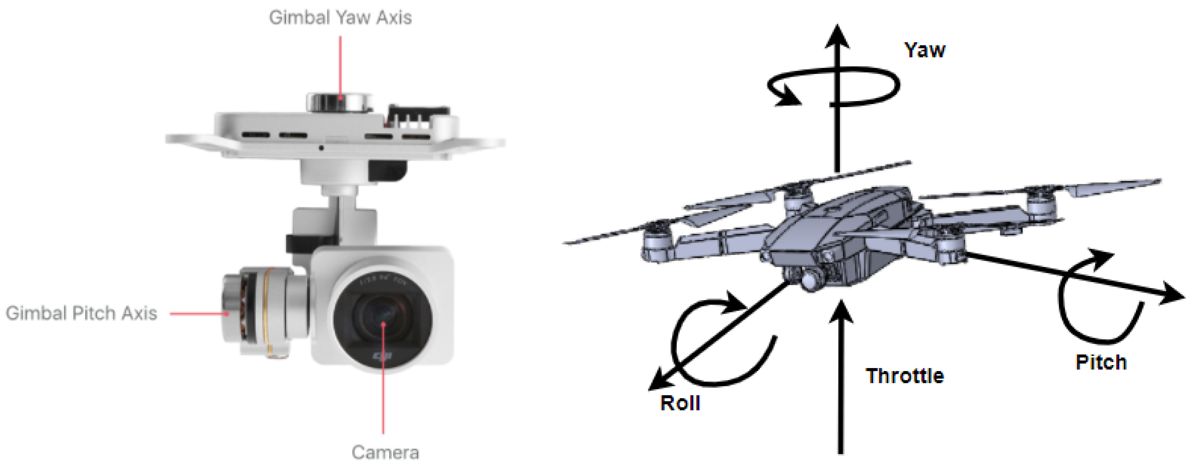
2.1. Drone Basic Sensors

Our main purpose in this article is to show the concept of a generic solution for common drones. For our method to work, the drone needs to have onboard optical flow sensor, camera, gimbal, IMU, and GNSS, which can be found on most common COTS drones.
The drone needs to be able to
  • Pitch: so it can move backwards and forwards.
  • Roll: so it can move left and right.
  • Yaw: so it can rotate.
  • Throttle: so it can change the altitude and move up and down.
The gimbal pitch range needs to be from −90° to +20° (see Figure 2).

2.2. Remote Control API

A common remote controller (see Figure 3) allows manual flight, gimbal and camera control, and provides a robust wireless control link for the drone.
The remote controller has sticks, wheels, switches, and buttons that give control. It has a USB connector for mobile devices.
These days, most controllers can link to a mobile device and the mobile device can communicate with the drone and receive the live video stream from the camera or send it commands that replace the remote controller buttons.

3. Modeling the Landing Process Commercial Drones

We can divide the drone world into CTOL (conventional take-off and landing) and VTOL (vertical take-off and landing); each has its own advantage. In this section, we would like to describe how a VTOL drone lands.

3.1. Landing Using GNSS

As we describe in the Related Works section, landing using GNSS is a common landing method; most GNSS drones have a return to home (RTH) or return to lunch (RTL) functionality. In the RTH method, the UAV records the home coordinate points; when activated, the drone will plan the short path to the home coordinate points and fly to them while keeping a certain altitude from the landing area. When the drone arrives above the landing area, it concentrates in relation to the home coordinates and lands.
The main problem of this method is that the drone cannot return to the home point when the GNSS signal is weak or unavailable. It lacks the accuracy and the versatility to adjust if the target moves or the signal is lost.

3.2. Vision-Based Landing

In this section we present the main concepts of visual landing on a known target, in particular, approximating the distance, the relative angle, and the relative velocity between the drone and the target. We start by presenting the basic concept of vertical visual landing—as often implemented in commercial drones.

3.2.1. Target

Vision-based solutions have many benefits: they are more accurate and can work indoors and outdoors in a dynamic environment. Most solutions rely on object recognition and edge detection techniques, which are improving every day. In vision-based solutions we want to be able to recognize the target, be able to concentrate due to the target, and be able to measure the distance from the target. In most vision-based solutions, the target is well known (predefined), which allows the drone to recognize and extract important information from the target’s known properties. For example, since we know the target’s real size, the distance to the target can be estimated. For future work, we would like to generalize the suggested method to “unknown targets” (not just predefined targets or known helipads), allowing the drone to spot “landable regions” and perform the VSL method on such occurring targets.

3.2.2. Controller Mode

When using vision-based landing there are three ways to approach the target.
Height: The height from the target. We will use parameters from downward vision system sensors.
Concentration: Centering the camera relative to the center of the helipad.
Distance: The distance from the target. To estimate the distance from the target we will use image processing (see Figure 4).
We need to set a PID controller (see Figure 5) for each mode in order to fix the drone’s desired position as smoothly and accurately as possible.

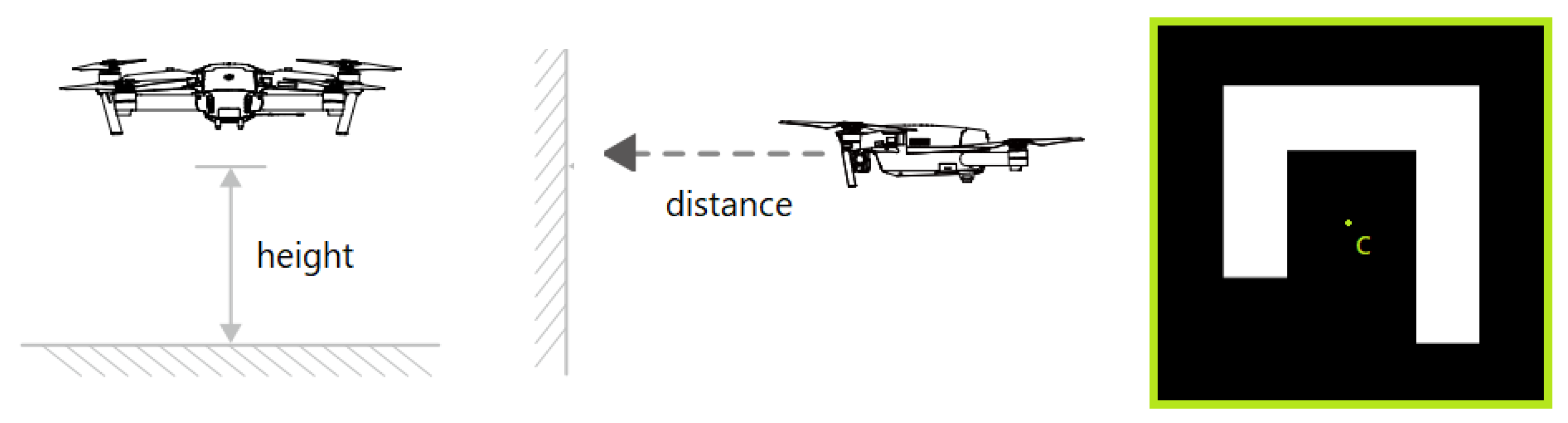
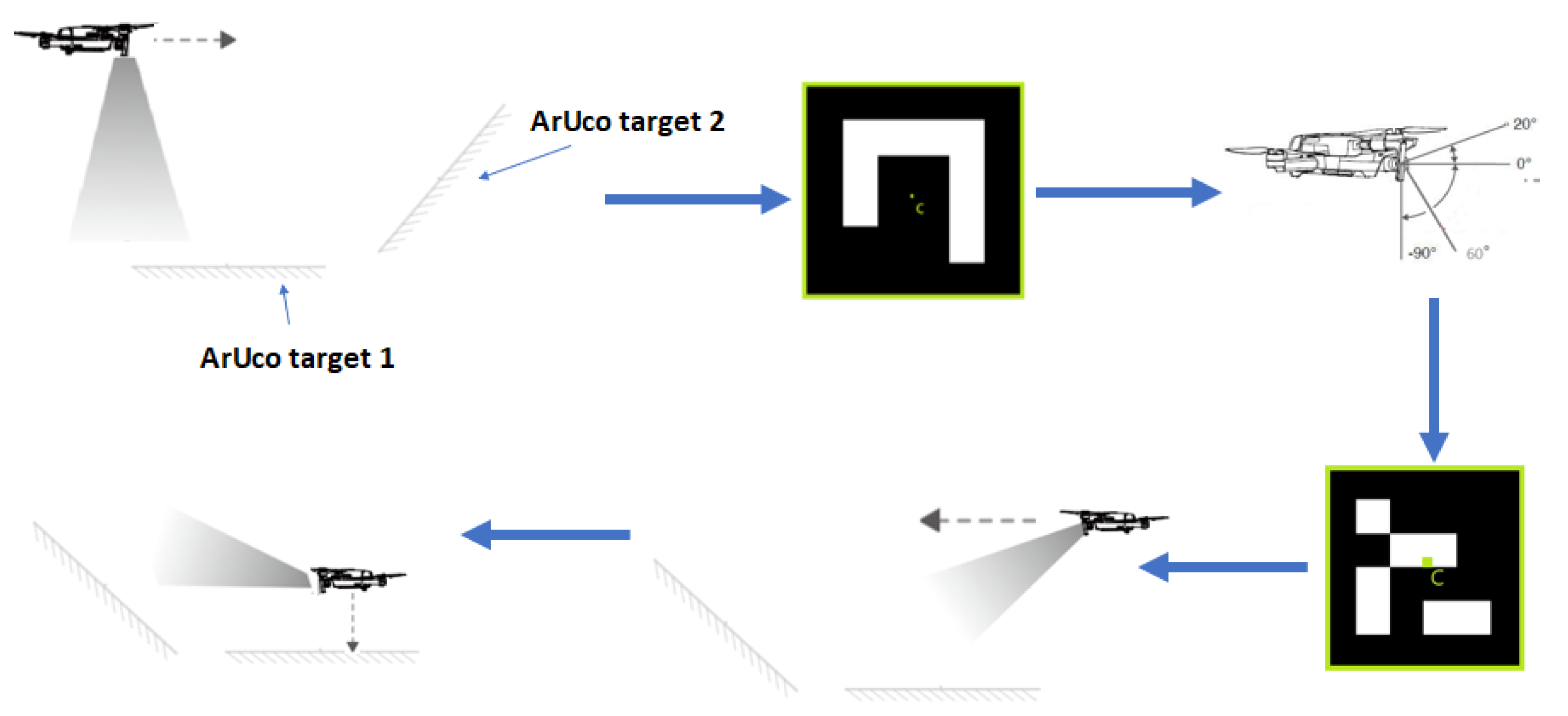
3.3. Distance Calculation Method

We can use a simple method in order to calculate the distance between the camera to the helipad. First, we will have to calibrate our system and find the focal length of the camera.
F = ( D ÷ W ) × P
where:
F = is the focal length of the camera.
W = is the known width of the marker.
P = is the apparent width in pixels.
D = is the distance from the camera to the object.
After finding the focal length we can use the same equation to find the distance between the camera to the helipad.
D = ( F × W ) ÷ P
This method will solve the 2D problem. In order to solve the 3D problem, we need to define our coordinate system (see Figure 6).
The next thing is to find the rotation matrix of the local system. In order to achieve this, we need to find the rotation matrix of the drone and the rotation matrix of the gimbal in relation to the target coordinate system.
The rotation matrix of the drone can be described by the following equation:
R d = c o s ( α ) c o s ( β ) c o s ( α ) s i n ( β ) s i n ( γ ) s i n ( α ) c o s ( γ ) c o s ( α ) s i n ( β ) c o s ( γ ) + s i n ( α ) s i n ( γ ) s i n ( α ) c o s ( β ) s i n ( α ) s i n ( β ) s i n ( γ ) + c o s ( α ) c o s ( γ ) s i n ( α ) s i n ( β ) c o s ( γ ) c o s ( α ) s i n ( γ ) s i n ( β ) c o s ( β ) s i n ( γ ) c o s ( β ) c o s ( γ )
The pitch rotation matrix of the gimbal can be described by the following equation:
R g = c o s ( θ ) 0 s i n ( θ ) 0 1 0 s i n ( θ ) 0 c o s ( θ )
The matrix rotation of the local system will be
R = c ( α ) c ( β ) c ( θ ) s ( θ ) [ c ( α ) s ( β ) c ( γ ) + s ( α ) s ( γ ) ] c ( α ) s ( β ) s ( γ ) s ( α ) c ( γ ) c ( α ) c ( β ) s ( θ ) + c ( θ ) [ c ( α ) s ( β ) c ( γ ) + s ( α ) s ( γ ) ] s ( α ) c ( β ) c ( θ ) s ( θ ) [ s ( α ) s ( β ) c ( γ ) c ( α ) s ( γ ) ] s ( α ) s ( β ) s ( γ ) + c ( α ) c ( γ ) s ( α ) c ( β ) s ( θ ) + c ( θ ) [ s ( α ) s ( β ) c ( γ ) c ( α ) s ( γ ) ] s ( β ) c ( θ ) s ( θ ) c ( β ) c ( γ ) c ( β ) s ( γ ) s ( β ) s ( θ ) + c ( θ ) c ( β ) c ( γ )
Another way to estimate the distance while avoiding using the rotation matrix is to measure the distance to each corner from the center and divide by four, and we obtain a good approximation of P (P is the apparent width in pixels).

Camera Gimbal Position

There are two ways to set the camera gimbal angle; the first approach is to fix the gimbal angle and the second approach is to let the gimbal be more flexible in order to adjust the angle due to the drone position.

Angle of −90°

The basic method for searching the target is to set the drone gimbal to be fixed to −90°. The helipad target will lay on the ground. The general steps in this method will be as follows (see Figure 7):
First we need to find the target.
Next, we will centralize the drone on the helipad center and hover over the target.
The final step is a safe landing.
The main problem with this method is losing sight of the target when the drone is too close to it, which can cause problems if the drone lands on a dynamic target that can suddenly change its height, for example, a target on a boat.

Angle of −45°

In this method, we will use one helipad target that will lie vertical to another helipad. The distance between the two helipads is fixed. The drone gimbal will be fixed to −45 degrees. The general steps in this method will be as follows (see Figure 8):
First, we need to find the target.
Next, we will reduce the distance to the target till we reach the “landing distance”.
Next, we will centralize the drone on the target center and hover over the helipad.
The final step is a safe landing.
The main problem with this method is that it is very difficult to identify the target unless the drone is in front of it.

Adjustable Angle

In this method, we will set two helipad targets, one bigger than the other. The biggest one lies on a horizontal surface. The second helipad target lies on a plain at a slope. The distance between the the two helipads is fixed. The drone’s gimbal pitch angle will be flexible and the angle can be adjusted from −90° to +20°. The general steps in this method will be as follows (see Figure 9):
First, we will find the largest helipad target.
Next, we will start to reduce the distance to the helipad target while changing the gimbal angle till we detect the second target.
We will reduce the distance to the second target till we reach the “landing distance”.
Next, we will centralize the drone on the second target center and hover over the helipad target.
The final step is to start the safe landing while changing the gimbal angle. That way we will not lose sight of the second target while we are landing.

4. Drone Landing Methodology

In this section we will present the overall VSL concept. We start by describing what we consider as a successful landing. The next step will be to describe the milestones in the basic landing algorithm and define the state machine.

4.1. Simulation of Autonomous Successful Landing

To illustrate a successful landing, several aspects need to be considered, such as the accuracy in landing and finding an efficient landing trajectory that allows reaching the goal in the shortest time and will be the most energy-efficient. And of course, will allow us to avoid objects that will interfere with the landing (see Figure 10).

4.2. Controlling Algorithms
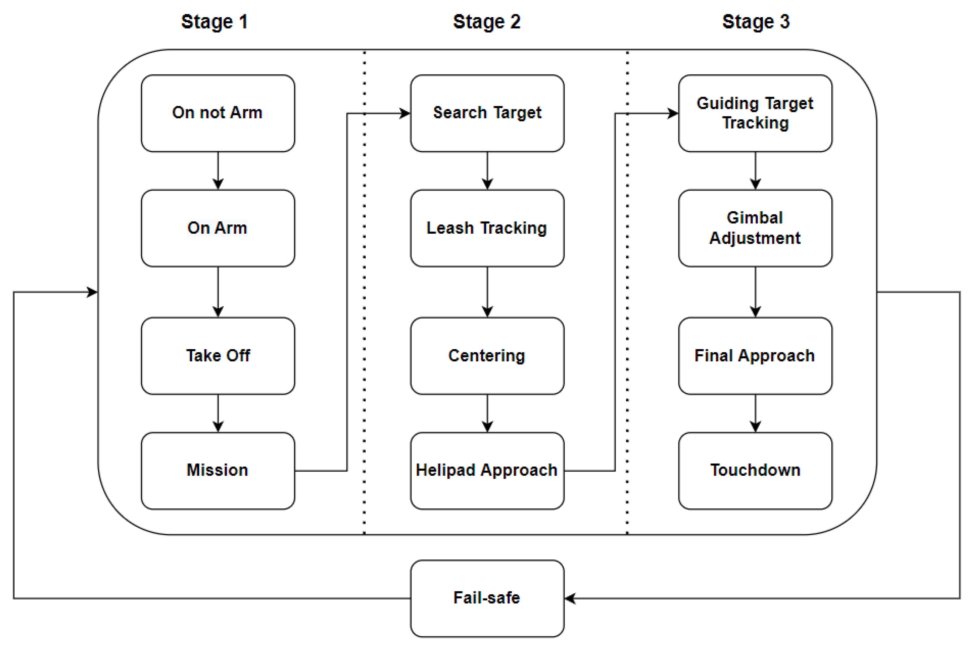
This section covers the control state machine and algorithm for the drone’s autonomous visual slide landing (VSL). We start by presenting the overall concept of VSL, including the landing platform. The landing platform includes two main targets: (i) helipad; (ii) guiding target (see Figure 11).
Informally the VSL use-case contains the following four steps: (a) At first, the drone tries to detect the helipad which is relatively horizontal and large and can be detected from a significant distance. (b) Then the drone approaches the helipad, while maintaining it in the center of the camera’s FoV. While approaching, the drone gimbal camera is tilted with respect to the distance between the drone and the helipad. (c) Once the drone can robustly detect the guiding target (which is smaller than the helipad and is oriented in a slope), the drone position itself at a fixed distance and angle relative to the guiding target. (d) In the final stage, the drone descends on the helipad vertically, while maintaining a fixed distance to the guiding target.
Before presenting the algorithm, we define several possible modes for the drone state machine (see Figure 12).

4.3. VSL Algorithm

The visual sliding landing (VSL) algorithm is based on the states defined above and state machine (see Figure 12).
  • Disarmed: The drone is on the ground not armed.
  • Arm: The drone is on the ground armed (ready to take off).
  • Take Off: The drone starts flying upwards and reaches a predefined altitude (e.g., 1 m).
  • Mission: The drone initiates a predefined route (mission) which is composed of several waypoints.
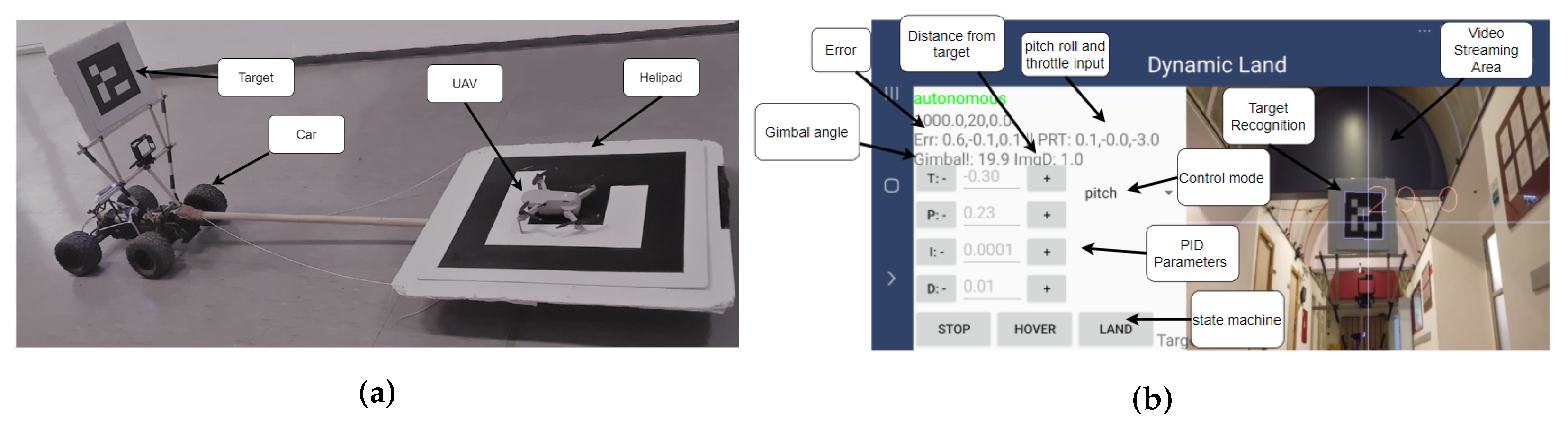
  • Search Target: The drone is looking for a known target (e.g., QR code) (see Figure 13).
  • Leash Tracking: The drone maintains the distance and orientation from the target. The “leash” is relatively flexible, allowing a smooth tracking. Note that in this mode the relative velocity between the drone and the moving target is close to zero.
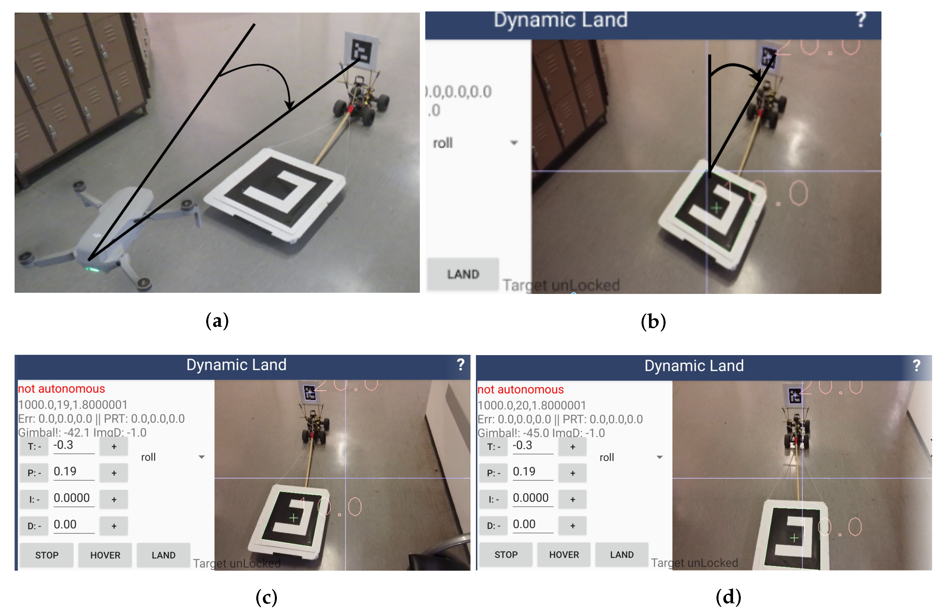
  • Centering: The drone maintains the detected target in the center of the image as captured by the drone gimbal camera. It can be achieved by using yaw roll and throttle; see Figure 14a–d.
  • Helipad Approach: Following the detection of the helipad target and executing centering process, the drone reaches a certain distance and angle to the helipad (i.e., approach funnel); see Figure 15a.
  • Guiding Target Tracking: This stage starts after the drone detects the guiding target. Then, it maintains “leash” and executes a centering process (according to the guiding target; see Figure 15b).
  • Gimbal Adjustment: The camera angle is moved according to the drop (e.g., distance 3 m, angle −45°).
  • Final Approach: The drone performs a vertical landing while maintaining a fixed distance from the guiding target, and adjusting the gimbal according to the height and the required descent rate from the helipad.
  • Touchdown: On touching the helipad, the drone shuts down the motors, reports “landing”, and moves to “arm” (or ready to fly) stage.
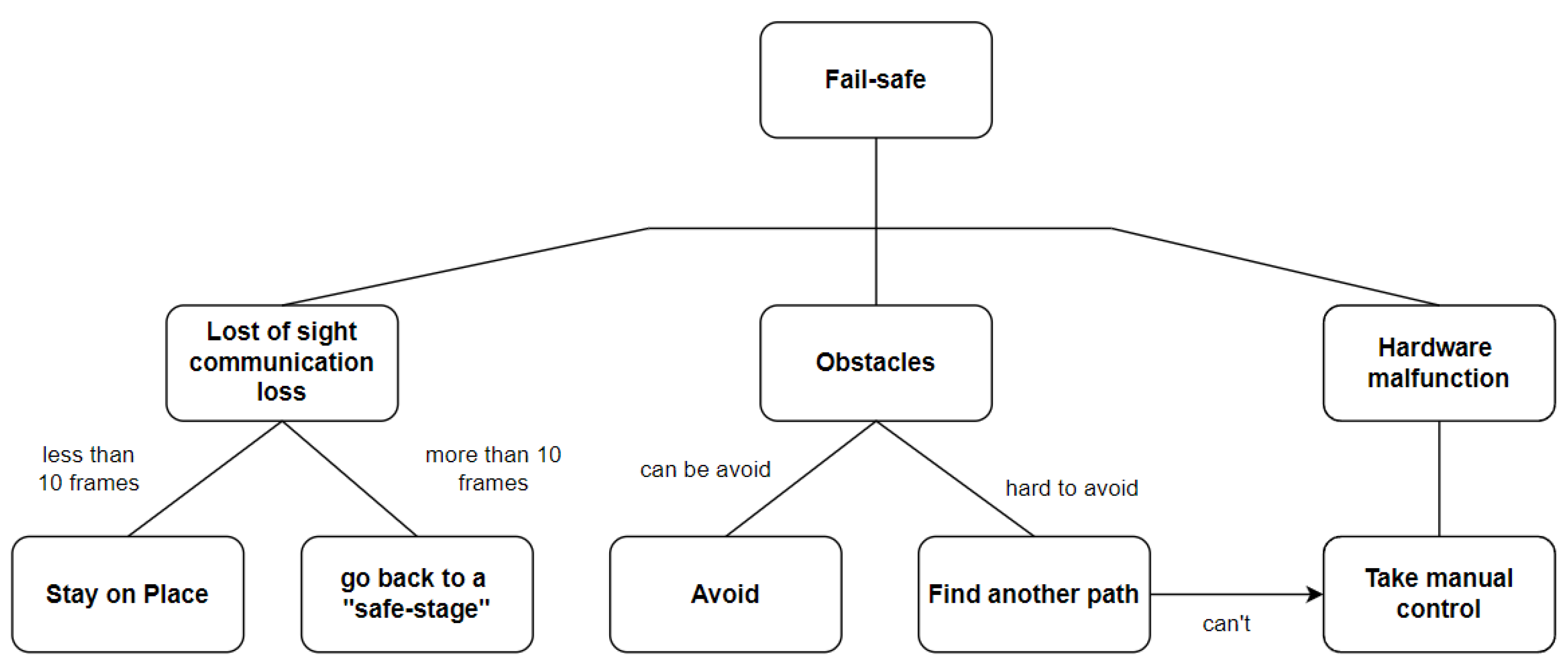
  • Fail-safe: The drone detects some kind of abnormality or risk, i.e., hardware malfunction, RC communication loss, or loss of sight of the target. The drone will return to a “safe-stage” according to the type of error and its fail-safe policy.

4.4. Fixed Camera Drones

Camera drones commonly have at least two axis gimbals, yet toy graded drones and FPV (first-person flight) drones often use a fixed (wide angle) camera for simplicity and reliability reasons. In order to adapt the suggested VSL method to drones with fixed (wide angle) camera, the following steps should be performed:
(i)
The wide-angle camera should be calibrated in order to improve the target detection and tracking.
(ii)
A virtual gimbal should be implemented on the camera image, by cropping the wide-angle frame into a standard FoV (field of view) image.
(iii)
In case the drone has standard FoV camera, the virtual gimbal can be implemented by changing the y-axis of the center point of the camera. In other words, the y-coordinate of the center of the image should be compensated according to the value as if the camera could be tilted by the gimbal.
The VSL algorithm can now be applied on the image as computed by the virtual gimbal. Thus, FPV drones and toy graded camera drones may also be using the suggested VSL method.

4.5. Safe Landing

As stated in the introduction, our main goal is to provide a landing method that could be robust in dynamic and challenging environments. Therefore, we would like to define safety envelope parameters and discuss how to proceed in “fail-safe” conditions, when the drone detects some kind of abnormality or risk. First, we define the safety envelope parameters (see Figure 16). The parameters can be divided into three groups:
(i)
Drone parameters: the drone working global behavioral parameters: e.g., max descent speed or max horizontal speed.
(ii)
Helipad parameters: e.g., type, size, or max slope (in our case, this should not be more than 20°).
(iii)
Drone to helipad parameters: e.g., drone to helipad relative speed, or marker tracking confidence (by the drone). The credibility factor is the overall combined parameter which takes into consideration all the parameters above and also checks for abnormality or risk. As mentioned, we also defined a fail-safe policy (see Figure 17).

4.6. Study Limitations

The presented framework was designed for commercial drones. Therefore, the following natural limitations should be dealt with. (i) Limited sensors: there are no airspeed sensors or lidar boards of most commercial drones. In fact, the suggested framework is applicable for any camera drone (even “toy-graded”), as the only sensors required onboard of the drone are IMU and camera. (ii) The autonomously landing controlling algorithms should be implemented on the remote control side, as most commercial drones do not have onboard SDK. This limitation introduces a controlling delay which should be compensated using the controlling algorithm. (iii) Safety: we limit the suggested framework to land-pads with predefined markers, and to operate within the safety envelope (as presented above).

5. Experimental Results

In this section, we present several landing experiments which were conducted in a few scenarios, including (i) static indoor landing (with no GNSS; see Figure 11b and Figure 18a–e); (ii) dynamic landing on rovers and cars (see Figure 19); (iii) dynamic landing on sailing boat (see Figure 20).

5.1. ArUco Tracking

In this work, ArUco markers were used as targets. Such targets can be detected using OpenCV library. Each detected target has both 2D and 3D parameters, including ID, center, corners, and orientation (normal). Given the camera’s field of view (FoV) and the physical size of an ArUco marker, OpenCV allows computing the distance and the vector from the camera to the marker. Using the orientation of the camera (as given by the gimbal), one can compute the drone to marker relative position.
For our target, we use the ArUco markers “10” and “20” (see Figure 13).
In order to estimate the accuracy of the ArUco target recognition by the drone’s visual sensors, we used several popular commercial drones (including DJI’s: Mavic Pro, Mavic Air, Mavic Air2, Mavic 2 Zoom, Mavic mini, and Phantom 4) and tested their landing performances using our framework. The suggested system was able to robustly detect and track a 160 × 160 mm ArUco markers within a range of 0.4–6.8 m, and an angular orientation of 0–60 degrees (between the target normal and the camera’s center orientation). Using larger marker (500 × 500 mm) with VGA resolution, the tested drones were able to recognize the marker from a 20 m range (using 1080 p resolution, this range may be increased to 50 m). The detection remained reliable in relatively dark conditions (down to 20 lux); in low-light conditions (below 20 lux), a low power LED (0.1 watt) emitting the target was sufficient for performing safe landing in total darkness. It should be noted that few recent drones have a downwards LED to allow optical-flow sensors in low light conditions; such an LED is sufficient for marker tracing in a range of 5 m, yet it requires an almost vertical landing. Thus, equipping a drone with a smartphone LED flash should be sufficient for performing a VSL in any light conditions. Using VGA 640 × 480 resolution, the marker tracking process was able to recordin 20–30 fps (on a standard Android smartphone), while the overall latency of the system was commonly 60–100 milliseconds, which we found to be sufficient for performing landing on moving targets with low dynamics (such as boats). The average relative error was 1.07% and max relative error 4.8% (using uncalibrated Mavic mini drone). This leads to a 1–5 cm landing accuracy in the common case of landing within a 1 m from the target. For more insights regarding accurate tracking optimization of QR markers, see [23,24].

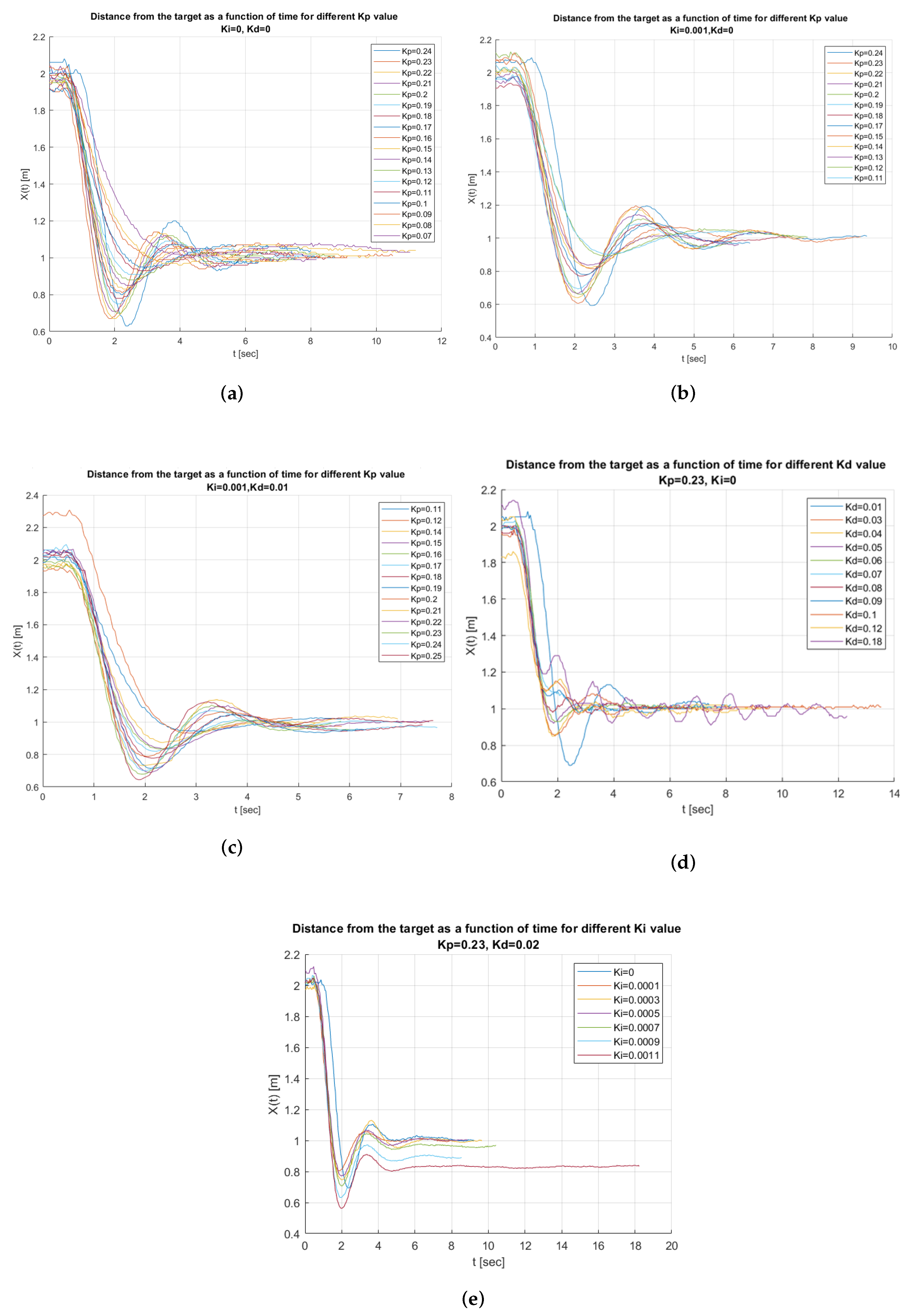
5.2. PID Calibration

As explained in the controller mode section, three important variables should be controlled: pitch, roll, and throttle. For each, we will have to find the right value of the PID parameters Kp, Kd, and Ki.
Kp is the proportional gain.
Kd is the derivative gain.
Ki is the integral gain.
There are several methods for tuning a PID, such as the Ziegler–Nichols method, which is a heuristic technique and tuning software that uses a numerical optimization technique.
Since we do not have the mathematical model of the system, and common PID tuning method did not work for our drone, we find the right PID parameters manually for each mode. Our priority will be the following:
  • The drone needs to have smooth reactions.
  • The fastest settling time (the time our system will converge to steady state).
  • The max overshoot cannot be more than half of the distance from the target needed to land (the distance between the target to the helipad).
We increase the Kp value until it reaches the ultimate gain, at which the output of the control loop has stable and consistent oscillations, and define it as the upper bound. For the lower bound, we decrease Kp until the system does not reach the desired value. After analyzing the results of our calibration experiments (see Figure 18), the following parameters lead to the best results for distance mode: Kp = 0.23, Ki = 0.0001, and Kd = 0.01, while the roll and throttle modes were controlled mainly by a simple proportional controller: Kp = 0.135 (Ki = 0.0, Kd = 0.0). We found that the PID parameters that we gained were good enough for different environments, but for obtaining better results we need to perform fine-tuning.

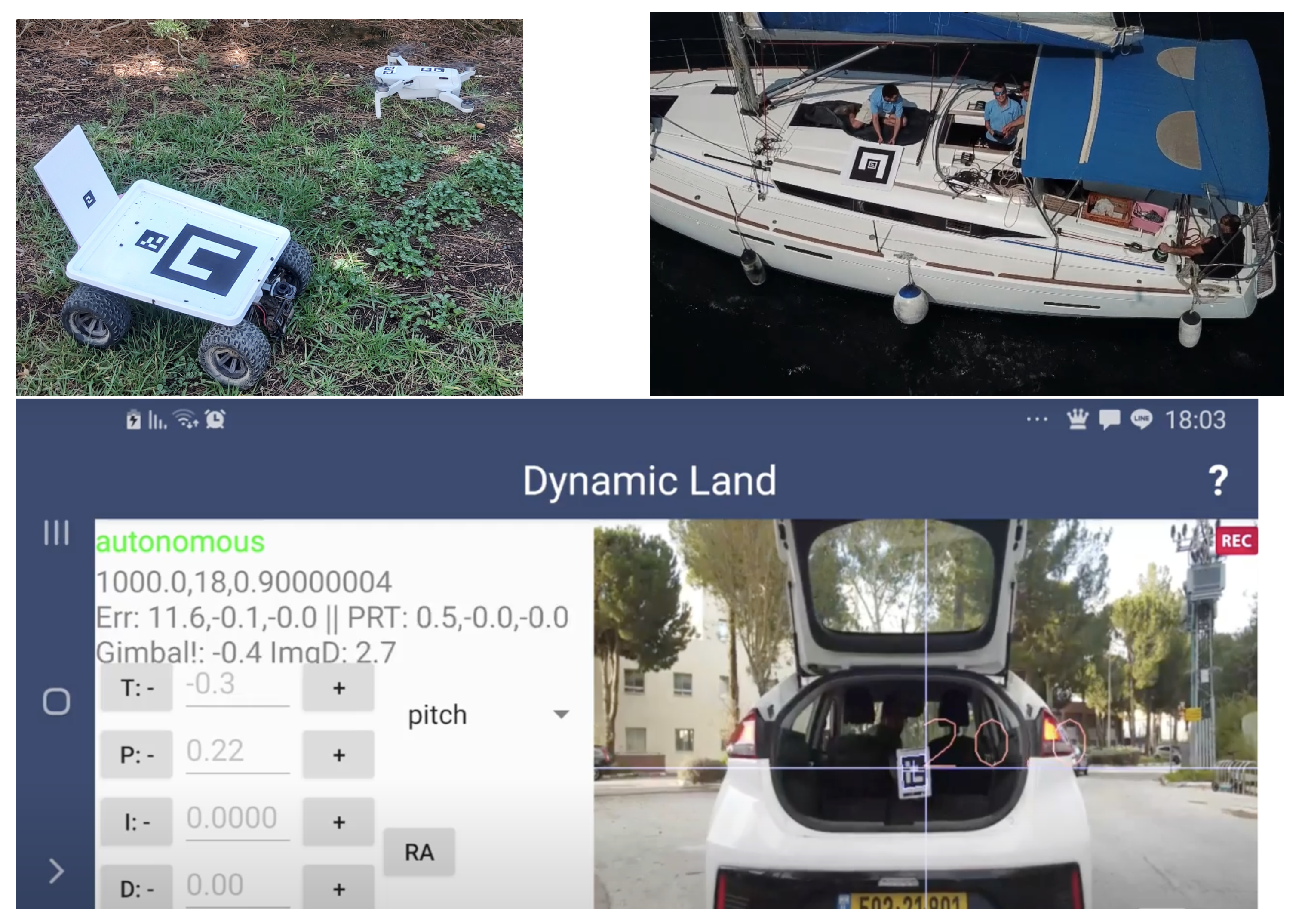
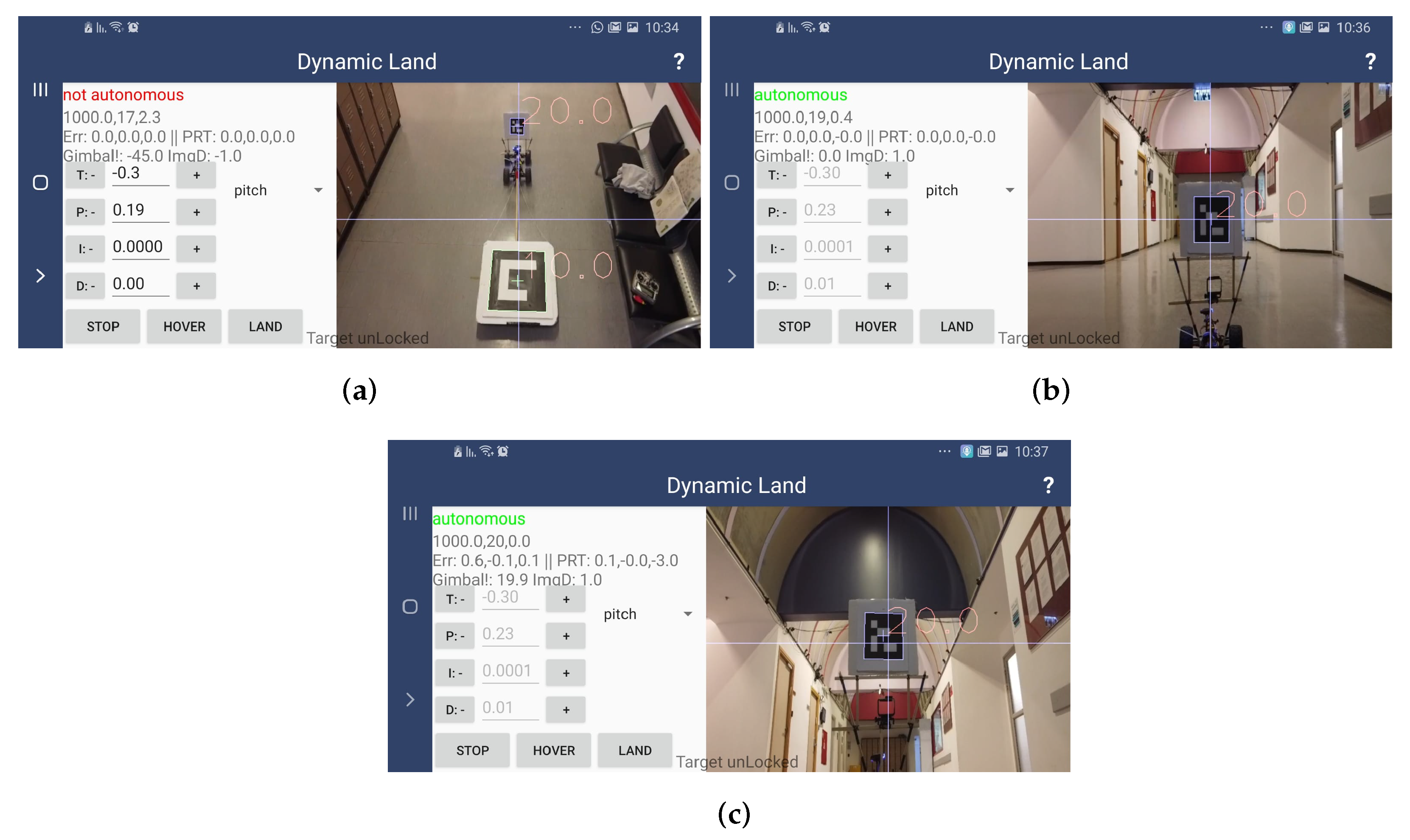
5.3. Experiment System

We would like to try our method on both static and dynamic systems. Our experiment system requires an ArUco target and a helipad on wheels. We also need a smartphone with the app we created using Android Studio based on DJI SDK. Our API (see Figure 11) includes a live streaming area, data about the error output, and pitch, roll, and throttle input command. We are able to update the PID parameters for each pitch, roll, and throttle. The app also has three main buttons:
  • Hover, which allows us to track the target and maintain a constant distance from it.
  • Land, which allows us to close the distance to the target and change the the gimbal pitch angle and decrease height while concentrating on the target.
  • Stop (most important button), which breaks the command that is running and allows us to take back control manually and control the drone from the remote control.

5.4. Experiment Strategy

As presented in the method section, we can break our experiment up into four stages:
  • Find the large target and approach it.
  • Fix the orientation.
  • Hover according to the smaller (landing) target.
  • Land according to a small target.

5.4.1. Fix the Orientation Error

We fix the orientation error in two steps (see Figure 14). We fix the yaw and then fix the roll error caused by fixing the yaw.

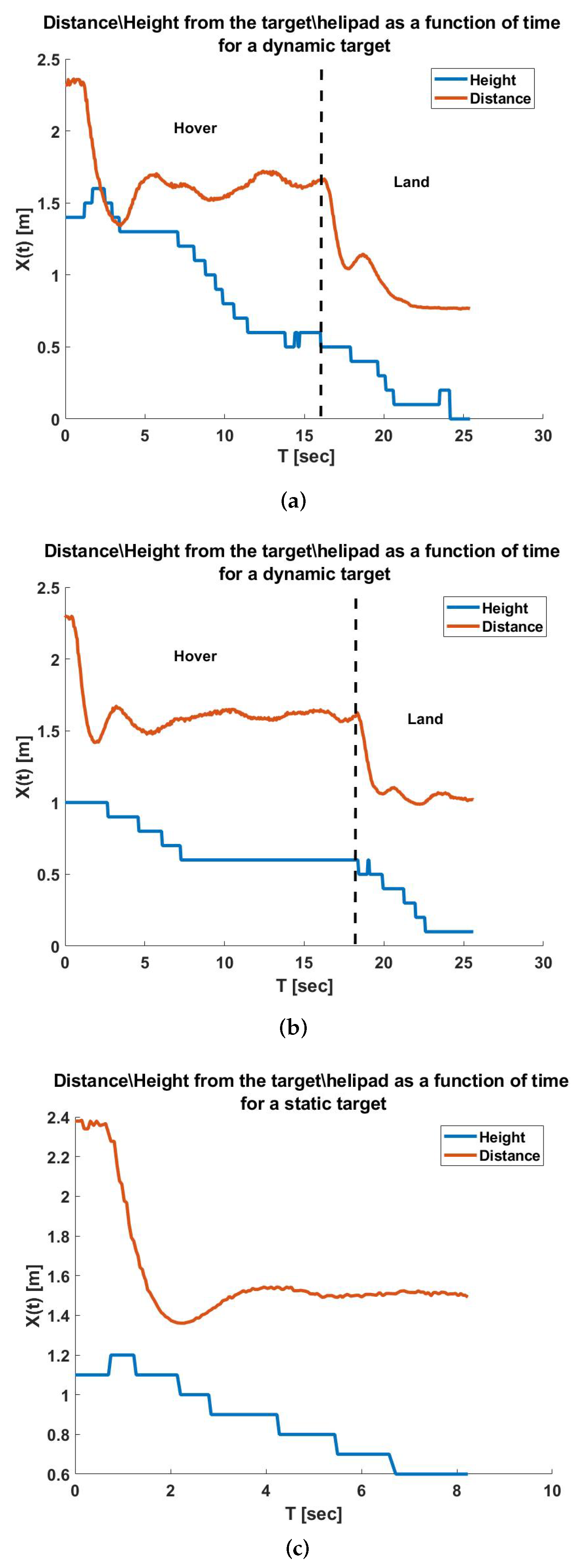
5.4.2. Hover and Landing

After fixing the orientation, we would like to shift the focus from the big target to the small target and keep a “leash” of 1.5 m from it while changing the gimbal angle to 0°. The next step will be landing, so to accomplish this we close the distance to 1 m and change the gimbal angle to 20° (see Figure 15).

5.4.3. Logging Results

Our API creates log data that log the drone flight parameters such as IMU, altitude, and the measurements gained from the image processing (see Figure 21).

6. Conclusions and Future Work

This paper presents the concept of diagonal autonomous visual landing on moving targets for commercial camera drones. The presented framework was designed and tested on a wide range of commercial drones in several scenarios, including (i) indoors: fixed targets, RC-rover moving targets; (ii) outdoors: boats, cars, and GNSS-denied urban cases.
There are several interesting directions for future work. We are currently working on improving the system to allow landing on high-speed targets. Another direction is to use the accurate landing capabilities in order to implement the concept of a “drone-in-a-box” for commercial off-the-shelf drones. Finally, we would like to generalize the suggested VSL solution for fix-wing VTOL drones.

Author Contributions

Conceptualization, A.K. and B.B.-M.; methodology, A.K.; software, A.K.; validation, A.K. and B.B.-M.; writing—original draft preparation, A.K.; writing—review and editing, A.K. and B.B.-M.; visualization, A.K.; supervision, B.B.-M. All authors have read and agreed to the published version of the manuscript.

Funding

This research received no external funding.

Institutional Review Board Statement

Not applicable.

Informed Consent Statement

Not applicable.

Data Availability Statement

The codes/simulations are available with the corresponding author and can be shared on reasonable request.

Acknowledgments

The authors would like to thank Ofek Darhi, Vlad Landa, Arkady Gorodishker, and Yael Landau for helping us with the Android implementation of the autonomous landing app.

Conflicts of Interest

The authors declare no conflict of interest.

References

  1. Casagrande, G.; Sik, A.; Szabó, G. Small Flying Drones; Springer: Berlin/Heidelberg, Germany, 2018. [Google Scholar]
  2. Aasen, H.; Honkavaara, E.; Lucieer, A.; Zarco-Tejada, P.J. Quantitative remote sensing at ultra-high resolution with UAV spectroscopy: A review of sensor technology, measurement procedures, and data correction workflows. Remote Sens. 2018, 10, 1091. [Google Scholar] [CrossRef] [Green Version]
  3. Cho, A.; Kim, J.; Lee, S.; Choi, S.; Lee, B.; Kim, B.; Park, N.; Kim, D.; Kee, C. Fully automatic taxiing, takeoff and landing of a UAV using a single-antenna GPS receiver only. In Proceedings of the 2007 International Conference on Control, Automation and Systems, Seoul, Korea, 17–20 October 2007; pp. 821–825. [Google Scholar]
  4. Smit, S.J.A. Autonomous Landing of a Fixed-Wing Unmanned Aerial Vehicle Using Differential GPS. Ph.D. Thesis, Stellenbosch University, Stellenbosch, South Africa, 2013. [Google Scholar]
  5. Baca, T.; Stepan, P.; Spurny, V.; Hert, D.; Penicka, R.; Saska, M.; Thomas, J.; Loianno, G.; Kumar, V. Autonomous landing on a moving vehicle with an unmanned aerial vehicle. J. Field Robot. 2019, 36, 874–891. [Google Scholar] [CrossRef]
  6. Saripalli, S.; Montgomery, J.F.; Sukhatme, G.S. Vision-based autonomous landing of an unmanned aerial vehicle. In Proceedings of the 2002 IEEE International Conference on Robotics and Automation (Cat. No. 02CH37292), Washington, DC, USA, 11–15 May 2002; Volume 3, pp. 2799–2804. [Google Scholar]
  7. Sharp, C.S.; Shakernia, O.; Sastry, S.S. A vision system for landing an unmanned aerial vehicle. In Proceedings of the 2001 ICRA. IEEE International Conference on Robotics and Automation (Cat. No. 01CH37164), Seoul, Korea, 21–26 May 2001; Volume 2, pp. 1720–1727. [Google Scholar]
  8. Lange, S.; Sunderhauf, N.; Protzel, P. A vision-based onboard approach for landing and position control of an autonomous multirotor UAV in GPS-denied environments. In Proceedings of the 2009 International Conference on Advanced Robotics, Munich, Germany, 22–26 June 2009; pp. 1–6. [Google Scholar]
  9. Wubben, J.; Fabra, F.; Calafate, C.T.; Krzeszowski, T.; Marquez-Barja, J.M.; Cano, J.C.; Manzoni, P. Accurate landing of unmanned aerial vehicles using ground pattern recognition. Electronics 2019, 8, 1532. [Google Scholar] [CrossRef] [Green Version]
  10. Sani, M.F.; Karimian, G. Automatic navigation and landing of an indoor AR. drone quadrotor using ArUco marker and inertial sensors. In Proceedings of the 2017 International Conference on Computer and Drone Applications (IConDA), Kuching, Malaysia, 9–11 November 2017; pp. 102–107. [Google Scholar]
  11. Marut, A.; Wojtowicz, K.; Falkowski, K. ArUco markers pose estimation in UAV landing aid system. In Proceedings of the 2019 IEEE 5th International Workshop on Metrology for AeroSpace (MetroAeroSpace), Turin, Italy, 19–21 June 2019; pp. 261–266. [Google Scholar]
  12. Paris, A.; Lopez, B.T.; How, J.P. Dynamic landing of an autonomous quadrotor on a moving platform in turbulent wind conditions. In Proceedings of the 2020 IEEE International Conference on Robotics and Automation (ICRA), Paris, France, 31 May–31 August 2020; pp. 9577–9583. [Google Scholar]
  13. Ruffier, F.; Viollet, S.; Amic, S.; Franceschini, N. Bio-inspired optical flow circuits for the visual guidance of micro air vehicles. In Proceedings of the 2003 International Symposium on Circuits and Systems, ISCAS ’03, Bangkok, Thailand, 25–28 May 2003; Volume 3, p. III. [Google Scholar]
  14. Saripalli, S.; Sukhatme, G.S. Landing a helicopter on a moving target. In Proceedings of the 2007 IEEE International Conference on Robotics and Automation, Rome, Italy, 10–14 April 2007; pp. 2030–2035. [Google Scholar]
  15. Zhang, X.; Liu, P.; Zhang, C. An integration method of inertial navigation system and three-beam lidar for the precision landing. Math. Probl. Eng. 2016, 2016. [Google Scholar] [CrossRef]
  16. Kong, W.; Zhou, D.; Zhang, Y.; Zhang, D.; Wang, X.; Zhao, B.; Yan, C.; Shen, L.; Zhang, J. A ground-based optical system for autonomous landing of a fixed wing UAV. In Proceedings of the 2014 IEEE/RSJ International Conference on Intelligent Robots and Systems, Chicago, IL, USA, 14–18 September 2014; pp. 4797–4804. [Google Scholar]
  17. Kong, W.; Zhang, D.; Zhang, J. A ground-based multi-sensor system for autonomous landing of a fixed wing UAV. In Proceedings of the 2015 IEEE International Conference on Robotics and Biomimetics (ROBIO), Zhuhai, China, 6–9 December 2015; pp. 1303–1310. [Google Scholar]
  18. Langåker, H.A.; Kjerkreit, H.; Syversen, C.L.; Moore, R.J.; Holhjem, Ø.H.; Jensen, I.; Morrison, A.; Transeth, A.A.; Kvien, O.; Berg, G.; et al. An autonomous drone-based system for inspection of electrical substations. Int. J. Adv. Robot. Syst. 2021, 18, 17298814211002973. [Google Scholar] [CrossRef]
  19. Alam, M.S.; Oluoch, J. A survey of safe landing zone detection techniques for autonomous unmanned aerial vehicles (UAVs). Expert Syst. Appl. 2021, 179, 115091. [Google Scholar] [CrossRef]
  20. Cohen, A.P.; Shaheen, S.A.; Farrar, E.M. Urban air mobility: History, ecosystem, market potential, and challenges. IEEE Trans. Intell. Transp. Syst. 2021, 22, 6074–6087. [Google Scholar] [CrossRef]
  21. Matus-Vargas, A.; Rodriguez-Gomez, G.; Martinez-Carranza, J. Ground effect on rotorcraft unmanned aerial vehicles: A review. Intell. Serv. Robot. 2021, 14, 99–118. [Google Scholar] [CrossRef]
  22. Praveen, V.; Pillai, S. Modeling and simulation of quadcopter using PID controller. Int. J. Control Theory Appl. 2016, 9, 7151–7158. [Google Scholar]
  23. Bolanakis, G.; Nanos, K.; Papadopoulos, E. A QR Code-based High-Precision Docking System for Mobile Robots Exhibiting Submillimeter Accuracy. In Proceedings of the 2021 IEEE/ASME International Conference on Advanced Intelligent Mechatronics (AIM), Delft, The Netherlands, 12–16 July 2021; pp. 830–835. [Google Scholar]
  24. Yu, J.; Jiang, W.; Luo, Z.; Yang, L. Application of a Vision-Based Single Target on Robot Positioning System. Sensors 2021, 21, 1829. [Google Scholar] [CrossRef] [PubMed]
Figure 1. The concept of visual sliding landing (VSL) of a drone on a moving target: (upper left) a DJI’s Mavic mini drone performing a 45° angle auto-VSL on a moving rover (using multi targets). (upper right) DJI’s Mavic Pro, performing 60° auto-VSL on a moving sailing boat. (down) the implementation of the suggested VSL method on an Android application as performing an almost horizontal (10°) auto-VSL into a moving car (using DJI’s Mavic air).
Drones 06 00098 g001
Figure 2. (left) DJI camera with gimbal; (right) a common UAV in quadcopter form.
Drones 06 00098 g002
Figure 3. A standard remote controller, from Dji’s Mavic Pro User Manual.
Drones 06 00098 g003
Figure 4. Height, distance, and concentration.
Drones 06 00098 g004
Figure 5. Basic scheme of PID controller.
Drones 06 00098 g005
Figure 6. Local coordinate system which includes 1. The coordinate system of the target, 2. The coordinate system of the drone, and 3. The coordinate system of the gimbal, 4. The global coordinate system.
Drones 06 00098 g006
Figure 7. Scanning, centralization, and landing.
Drones 06 00098 g007
Figure 8. Scanning, distance reducing, centralizing, and landing.
Drones 06 00098 g008
Figure 9. Scanning for first target, detecting first target, distance reducing and angle changing, detecting second target, distance reducing, centralizing, and landing.
Drones 06 00098 g009
Figure 10. Slide landing: The concept of visual adaptive angle landing of a drone on a moving target. The change in the landing vector is due to the shift of focus from the big target to the small target.
Drones 06 00098 g010
Figure 11. (a) Our experiment system setting includes moving target helipad and Mavic mini. (b) The image as captured from landing position on the helipad. Our API includes video streaming area, real-time data, PID parameters, and state machine.
Drones 06 00098 g011
Figure 12. The generic VSL algorithm.
Drones 06 00098 g012
Figure 13. ArUco markers “10” and “20”.
Drones 06 00098 g013
Figure 14. Fix the orientation error. (a) The orientation error from top view. (b) The orientation error from the app screen. (c) The roll error after fixing the yaw. (d) The orientation after fixing both yaw and roll error.
Drones 06 00098 g014
Figure 15. The experiment is divided into three steps. (a) Recognition of both target and helipad. (b) Closing distance while changing gimbal angle from −45° to 0°, and hovering in relation to the target. (c) Start landing and changing the gimbal angle value from 0° to 20°.
Drones 06 00098 g015
Figure 16. Safety envelope parameters.
Drones 06 00098 g016
Figure 17. Fail-safe policy.
Drones 06 00098 g017
Figure 18. Data results for testing different values of the PID parameters Kp, Kd, and Ki for distance mode where we control the pitch. (a) Testing system response for different Kp values while Kd = 0, Ki = 0. (b) Testing system response for different Kp values while Kd = 0, Ki = 0.0001. (c) Testing system response for different Kp value while Kd = 0.01, Ki = 0.0001. (d) Testing system response for different Kd value while Kp = 0.23, Ki = 0. (e) Testing system response for different Ki values while Kp = 0.23, Kd = 0.02.
Drones 06 00098 g018
Figure 19. An almost horizontal landing into a moving car (back door). The top image shows the first detection of the landing marker. The second image was taken after the autonomous mode was engaged (see “toast” of a “virtual sticks enabled”). The third image shows the drone maintaining a fixed (leashed) distance and angle from the target, and once this distance is maintained successfully for few seconds, the drone is landing, as shown in the bottom image.
Drones 06 00098 g019
Figure 20. Slide landing: Mavic Pro (DJI) performing an adjustable tracking and approaching to a moving boat. This is an example of a case in which a diagonal sliding landing is needed as, due to obstacles such as the sails and wires, a vertical landing cannot be performed.
Drones 06 00098 g020
Figure 21. (a,b) Results of two successful experiments of hovering and landing on moving targets. There are two zones in the graph, “hover zone” and “land zone”. The upper line represents the distance from the target, and the lower line represents the height from the surface. (c) Result of successful landing on static target.
Drones 06 00098 g021
Publisher’s Note: MDPI stays neutral with regard to jurisdictional claims in published maps and institutional affiliations.

