Article

Automating Aircraft Scanning for Inspection or 3D Model Creation with a UAV and Optimal Path Planning

Department of Aerospace Engineering and Engineering Mechanics, University of Cincinnati, 2600 Clifton Ave, Cincinnati, OH 45221, USA
*
Author to whom correspondence should be addressed.
Drones 2022, 6(4), 87; https://doi.org/10.3390/drones6040087
Submission received: 3 March 2022 / Revised: 24 March 2022 / Accepted: 25 March 2022 / Published: 28 March 2022

Abstract

:
Visual inspections of aircraft exterior surfaces are required in aircraft maintenance routines for identifying possible defects such as dents, cracks, leaking, broken or missing parts, etc. This process is time-consuming and is also prone to error if performed manually. Therefore, it has become a trend to use mobile robots equipped with visual sensors to perform automated inspections. For such a robotic inspection, a digital model of the aircraft is usually required for planning the robot’s path, but a CAD model of the entire aircraft is usually inaccessible to most maintenance shops. It is very labor-intensive and time-consuming to generate an accurate digital model of an aircraft, or even a large portion of it, because the scanning work still must be performed manually or by a manually controlled robotic system. This paper presents a two-stage approach of automating aircraft scanning with an unmanned aerial vehicle (UAV) or autonomous drone equipped with a red–green–blue and depth (RGB-D) camera for detailed inspection or for reconstructing a digital replica of the aircraft when its original CAD model is unavailable. In the first stage, the UAV–camera system follows a predefined path far from the aircraft surface (for safety) to quickly scan the aircraft and generate a coarse model of the aircraft. Then, an optimal scanning path (much closer to the surface) in the sense of the shortest flying distance for full coverage is computed based on the coarse model. In the second stage, the UAV–camera system follows the computed path to closely inspect the surface for possible defects or scan the surface for generating a dense and precise model of the aircraft. We solved the coverage path planning (CPP) problem for the aircraft inspection or scanning using a Monte Carlo tree search (MCTS) algorithm. We also implemented the max–min ant system (MMAS) strategy to demonstrate the effectiveness of our approach. We carried out a digital experiment and the results showed that our approach can scan 70% of the aircraft surface within one hour, which is much more efficient than manual scanning.

1. Introduction

Visual inspections are usually required for ensuring the airworthiness of an aircraft in the maintenance routine [1]. The traditional method of visual inspection is time-consuming and error-prone, as it requires human inspectors to visually inspect the entire aircraft exterior body to identify possible anomalies such as dents, cracks, leaking, broken or missing parts, etc., and manually measure the parameters of the found defects. Robotics-based inspection methods are being developed for aircraft inspection for reducing the workload, time, and cost of defect detection. These methods use unmanned ground vehicles (UGVs) [2] or unmanned aerial vehicles (UAVs) [3,4] equipped with laser scanners or cameras to perform nondestructive inspection around the aircraft. The inspection vehicles either follow human operators’ guides or automatically navigate themselves based on an existing map of the environment to acquire images or other sensed data of the aircraft. These images or data can be used for defect identification and analysis, leveraging the power of machine learning techniques. Furthermore, automating the robotic inspection procedure without human intervention can significantly improve the efficiency of aircraft visual inspection. Many studies on this automatic robotic inspection employed UAVs to inspect large structures [5,6], specifically an aircraft [7]. One key to the automatic robotic inspection is to solve the coverage path planning (CPP) problem to compute an optimal inspection path for the robotic inspection system, which requires a pre-existing CAD model of the target structure [8]. All these studies assumed that a 3D mesh model of the target object is available and can be used for solving the CPP problem. Unfortunately, for aircraft inspection, such a 3D model may not be accessible to small and medium maintenance, repair, and overhaul (MRO) shops due to reasons such as the original 3D models of old aircraft may be missing, the original design may not match the current aircraft whose exterior may have been changed due to aging or alternation, or, in the most likely case, the original CAD model of the aircraft is inaccessible to the maintenance crew due to policy, process, or software constraints. Therefore, instead of creating a 3D CAD model of the aircraft from scratch, which is time-consuming, and requires professional designers, 3D scanners such as laser scanners and red–green–blue and depth (RGB-D) cameras can be used to generate a digital model of the target aircraft because of their efficient manner of 3D model reconstruction [9,10]. However, manually scanning a large aircraft using 3D scanner shares the same drawbacks as visually inspecting the aircraft. Similar to using UAVs for inspection, automating the aircraft scanning using UAVs equipped with 3D scanners can significantly improve the efficiency and quality because UAVs have been successfully applied in many other applications in surveying, mapping, and surveillance [11], as well as in wireless networks [12], due to their inherent attributes such as mobility, flexibility, and adaptive altitude. In addition, it is possible for small MROs to effectively use UAV technology and apply the “smart MRO” principle in the pre-flight inspection of aircraft [13].
Aiming to automate the aircraft scanning and inspection when a 3D model of the aircraft is unavailable, we developed a two-stage approach of aircraft scanning using a UAV equipped with an RGB-D camera in this paper, based on our previous research [14]. The goal of our approach is to generate a dense and precise 3D digital model of the target aircraft in a form of point cloud which could be used to compute an inspection path for guiding the robotic inspection procedure, and the UAV needs to finish the scanning or inspection process in a time-efficient manner, considering its constraint of short battery life. To ensure the precision of the generated point cloud model, we employed an indoor GPS system due to its advantages of large measurement range, non-contact, and easy setup [15]. In addition, the indoor GPS system can achieve millimeter-level accuracy when tracking a slowly moving object, which makes it suitable for both stages of scanning [16]. Therefore, in a static MRO environment with an indoor GPS system, the UAV–camera system follows a predefined path to quickly reconstruct a coarse model of the aircraft in the first stage. However, the low-resolution and low-accuracy model is not qualified for guiding the UAV–camera system to perform a safe and detailed inspection task. The UAV–camera system needs to closely scan the aircraft for the purpose of reconstructing a dense and precise digital model in the second stage. The resulting model then can be used for aircraft inspection, maintenance, or even as a key component of a digital twins to support the operational prediction and prognosis of the aircraft [17]. In order to automate the scanning in the second stage, an ”optimal” scanning path for fully covering the area of interest of the target aircraft with short flying distance must be computed. We solved this CPP problem using a Monte Carlo tree search (MCTS) algorithm, which can be seen as a reinforcement learning (RL) technique, and it was applied in the difficult problem of computer Go [18]. We also implemented a population-based heuristic optimization algorithm named max–min ant system (MMAS) [19] to demonstrate the effectiveness of our two-stage approach of aircraft scanning.
The rest of this paper is structured as follows. Section 2 introduces the existing methods for aircraft scanning and inspection, including the solutions of the CPP problem. Section 3 describes the proposed two-stage approach of aircraft scanning. Section 4 provides a simulation of solving the CPP problem in simplified scenarios with both the MMAS and the MCTS algorithms. Section 5 presents digital experiments with an example aircraft. Finally, a conclusion is drawn and future works are discussed to end our paper.

2. Related Work

Path planning has been one of the most important research problems in the UAV field, aiming at finding an optimal path from an initial location to a destination location. Different studies have been conducted, for example, with a focus on constraint optimization [20], computational intelligence [21], and multi-UAV cooperative path planning [22]. A general review of UAV path planning techniques and challenges was discussed in [23]. For specific application of aircraft scanning and inspection, UAVs equipped with cameras were employed for collecting image data that can be used to create detailed 3D models of an Airbus fleet [24]. Such solutions were also adopted in small MRO companies to develop procedures for providing inspection solution for airports operations. In fact, as an aircraft is large and its shape is complex, the path planning problem, as a key task of automated robotic scanning and inspection using the UAV–camera system, remains challenging. This problem is referred to as the CPP problem, a non-deterministic polynomial time-hard problem, which is for computing an ”optimal” path in terms of flying distance, flying time, or energy consumption of the UAV to fully cover the exterior area of interest of the target aircraft. Considering that aircraft scanning and inspection in MRO shops is usually in a static environment, the CPP problem can be solved offline based on an existing digital model of the aircraft. Many studies [25,26,27] tackled the CPP problem in two steps by solving a set covering problem (SCP), following solving a traveling salesman problem (TSP). The SCP algorithms find the smallest set of viewpoints for covering the entire area of scanning, and typical SCP algorithms are the greedy algorithm and its variants. The TSP algorithms find the shortest path for visiting all viewpoints selected by the SCP algorithms, and popular algorithms are population-based optimization algorithms such as genetic algorithm, ant colony optimization (ACO), and particle swarm optimization. Instead of dividing the CPP problem into two sub-problems, other researchers studied one integrated solution for achieving multiple objectives, which are maximizing coverage and accuracy, while minimizing flying distance, time, or energy consumption. Phung et al. [28] formulated the inspection path planning problem as an extended TSP in which both the coverage and obstacle avoidance were taken into account. They proposed an enhanced discrete particle swarm optimization algorithm to solve the extended TSP for robotic inspection of large surfaces. Almandhoun et al. [7] developed the adaptive search space coverage path planner algorithm for aircraft inspection using a graph search algorithm instead of TSP algorithms. They produced a discretized sample space which consists of a set of viewpoints, and the sample space was used to generate the search space by graphically connecting samples with their neighbors. The algorithm also included a heuristic function that evaluates the expected information gain of the waypoints by updating a probabilistic volumetric map represented as an octree. This approach was extended by Silberberg et al. in [29] for developing a visual inspection system of military aircraft using a multi-rotor UAV, and their analysis showed that multi-rotor UAVs are a viable inspection platform for military aircraft. More generally, the CPP problem of inspection by UAVs could be solved using grid-based methods, which guarantee a complete coverage of the target scenario by applying cellular decomposition in the area of interest and splitting the target-free space into cells in order to simplify the coverage [30]. The grid-based maps were also leveraged in Kyaw et al.’s solution for optimizing the CPP problem in large complex environments based on the TSP and deep RL [31]. They decomposed the environment to form a TSP problem and determined the solution to the TSP by training a recurrent neural network with long short-term memory layers using RL.
The above studies for large structure inspection with a UAV–camera system require a pre-existing mesh model of the inspected structure for solving the CPP problem. However, for most MRO shops, such a model is often unavailable, or very difficult to obtain. This makes our approach of aircraft scanning and inspection unique because it does not need an existing mesh model, and hence is beneficial to those businesses. Our method is still applicable if an existing aircraft model is available. In this case, one can omit the first stage and directly proceed to the second stage of the method. Our contributions include that (1) we proposed a method for scanning large aircraft using a UAV and an RGB-D camera without need of a pre-existing model; (2) we solved the surface coverage path planning problem using a Monte Carlo tree search algorithm based on a coarse model of the aircraft; (3) we demonstrated that our two-stage method can scan or inspect the large aircraft much more efficiently than manual scanning.

3. Methodology

3.1. UAV–Camera Scanning System

The UAV–camera scanning system consists of a UAV and an RGB-D camera. The camera is installed on the UAV and can be tilted upward and downward with respect to the UAV. For UAV localization, we employ an indoor GPS system which consists of three or more transmitters and at least three sensors. The transmitters continually generate laser fanned beams and the sensors are placed on the UAV with a fixed formation to receive the transmitters’ signals. The position and the orientation of the UAV can thus be calculated based on the positions of the sensors. The architecture of the two-stage scanning system is shown in Figure 1. A control station is used for point cloud data alignment, candidate viewpoints generation, coverage path planning, and UAV–camera system control. The data communication between the control station and the UAV–camera system is based on the Robot Operating System (ROS) [32] through a wireless communication network.

3.2. Coarse Model Acquisition

RGB-D cameras have limited field of view (FOV) and, thus, plenty of data frames need to be aligned together to form a global model of the aircraft if the UAV works at a close distance to the aircraft. In order to reduce the time of generating a coarse model, the UAV is controlled to automatically fly along a predefined path with a large working distance so that a smaller number of image frames needs to be acquired and possible collision can be easily avoided. When the UAV is hovering at a specific position for acquiring data, the position [ x q , y q , z q ] and the orientation [ ϕ q , θ q , ψ q ] of the UAV can be obtained through the indoor GPS system in real time. With the camera tilt angle θ known, the position and the orientation of the camera with respect to the global frame established by the indoor GPS system can be calculated using forward kinematics. Thus, we can obtain a transformation matrix for aligning the captured point cloud data into a global model using
w P = c w T c P
where c P is the vector of a 3D point in the camera coordinate frame, w P is the vector of the same 3D point in the global coordinate frame, and c w T is the transformation matrix for mapping the point from the camera frame to the global frame. The point cloud data frames are aligned together using the Point Cloud Library [33]. Noisy data in each data frame are filtered by applying the sparse outlier removal method. Then, to simplify the large-scale point cloud, a voxel-grid-based downsampling method is applied to the input data frame before aligning it with the global model. An example of the resulted coarse digital model in octree representation is shown in Figure 2.

3.3. Viewpoint Generation

To scan or inspect the aircraft, the camera must be placed at a specific pose, which is also known as viewpoint, denoted as [ x c , y c , z c , ϕ c , θ c , ψ c ] where [ x c , y c , z c ] are the 3D position of the camera and [ ϕ c , θ c , ψ c ] are roll, tilt, and heading angles of the camera with respect to the global frame. A viewpoint is determined by offsetting the camera with a specified safety working distance from a point of the surface along the surface normal. At this viewpoint, we can compute the position [ x q , y q , z q ] and the yaw ψ q of the UAV and the tilt angle θ of the camera using inverse kinematics. To simplify the problem, we assume the roll of the camera to be zero. In addition, the roll and pitch of the UAV is also assumed to be zero when it is hovering.
In order to generate sufficient viewpoints to cover the entire area of interest, a set of candidate viewpoints needs to be computed. Based on the octree representation of the coarse model, for each voxel, the surface normal of the voxel is estimated based on the points in the voxel. By offsetting the camera with the specified working distance along the voxel’s normal, a candidate viewpoint can be determined, and its viewshed can then be computed by examining visible octree voxels using the frustum culling method. Therefore, the generated candidate viewpoints are uniformly distributed over the area of interest for ensuring the full coverage. An example of the candidate viewpoint and its viewshed (visible voxels are marked in red cube) is shown in Figure 3.

3.4. Coverage Path Planning

3.4.1. Max–Min Ant System

The CPP problem of aircraft scanning or inspection can be solved in two steps, applying heuristic optimization algorithms. In the first step, we simply apply the greedy algorithm to solve the SCP for finding a minimum set of viewpoints that fully covers the area of interest of the target aircraft. The SCP in our paper is defined as follows: Given a universe U of voxels that represents the target area of scanning or inspection, a collection of subset S = { S 1 , S 2 , S m } , where every subset S i represents the i’th viewpoint in total m candidate viewpoints and the subset has an associated cost, find a minimum cost sub-collection of S that covers all voxels of U. The greedy algorithm may not always provide an optimal solution; hence, we run the algorithm multiple times and choose the best one as the one for the following TSP. In the second step, we apply the MMAS algorithm to solve the TSP to find an approximate shortest path for visiting all the viewpoints selected from the first step.
MMAS is an ACO algorithm extended from ant systems, the first ACO algorithm, that was inspired by the foraging behavior of real ants. ACO algorithms make use of artificial ants which iteratively construct candidate solutions to a combinatorial optimization problem. The construction is guided by artificial pheromone trials and problem-dependent heuristic information. Typically, solution components which are used by more ants will receive a higher amount of pheromone and, hence, will more likely be used by the ants in future iterations of their strategy. The MMAS algorithm only allows the best solution found during an iteration or the run of the algorithm to update the pheromone trail for avoiding early search stagnation to achieve the best performance of the algorithm. When applying the MMAS algorithm to the TSP, ants are randomly placed on chosen cities initially. To construct a tour, each ant moves to a "city" which has not been visited based on a probabilistic decision which is biased by the pheromone trail τ i j ( t ) and locally available heuristic information η i j . An ant k currently located at city i chooses city j to go to with a probability as follows:
p i j k ( t ) = ( τ i j ( t ) ) α · ( η i j ) β l N i k ( τ i l ( t ) ) α · ( η i l ) β j N i k
where α and β determine the relative importance of the pheromone trail and the heuristic information and N i k is the feasible neighborhood city of ant k. Pheromone trails τ i j ( t ) associated with each arc ( i , j ) are modified through pheromone trail evaporation and pheromone trail reinforcement by the ants, which is defined as
τ i j ( t + 1 ) = ρ · τ i j ( t ) + τ i j b e s t
where parameter ρ (with 0 ρ < 1 ) is the trail persistence, Δ τ i j b e s t = 1 / f ( s b e s t ) , and f ( s b e s t ) denotes the solution cost of either the iteration-best or the global-best solution.

3.4.2. Monte Carlo Tree Search

Instead of dividing the CPP problem into two sub-problems and solving them separately, we propose a neighborhood viewpoints-based MCTS algorithm to solve the CPP problem for the aircraft scanning or inspection. For a viewpoint in the candidate viewpoints, its neighborhood viewpoints are the viewpoints that have overlapped voxels in their viewsheds. In order to find the best neighborhood viewpoints of a selected viewpoint, we score all the rest of the viewpoints based on the distance to the selected viewpoint and the number of overlapped voxels with the selected one. Then, the lowest-scored viewpoint appears to be the best neighborhood viewpoint as it is close to the selected viewpoint and does not share the same voxels. We can select one or more neighborhood viewpoints based on the score. These neighborhood viewpoints are the possible next viewpoints to visit during MCTS tree expanding.
Starting from a root node, which represents the starting viewpoint, the MCTS algorithm selects a child node, representing a neighborhood viewpoint, to explore if the current node is not fully explored (i.e., some of its neighborhood viewpoints have not been visited). Then, a rollout simulation based on randomly choosing an untried neighborhood viewpoint to visit is played until the desired coverage ratio is reached or the neighborhood viewpoints are all visited. The result of the simulation is a reward r considering the coverage ratio r c o v e r a g e , overlap ratio r o v e r l a p , and total traveled distance d t r a v e l . The reward is defined as
r = c 1 · r c o v e r a g e c 2 · r o v e r l a p c 3 · d t r a v e l
where c 1 , c 2 , and c 3 are the control parameters for weighting the coverage ratio, the overlap ratio, and the total traveled distance. In this paper, c 1 is set to be 100.0 , c 2 is 10.0 , and c 3 is 0.01 . The reward of each simulation rollout is backpropagated to current child node and its parent nodes in the tree. Therefore, for one specified node, the best action of choosing a child node v to visit can be determined once all of its child nodes are explored, and the best child policy is defined as
v = arg max v V ( σ · q v + ( 1 σ ) · R v N v )
where V is the set of child nodes of the current node, and σ is a hyperparameter for controlling the weighted combination of the average reward ( R v N v where R v is total reward; N v is visit count) and the maximum reward q v in a simulation for a child node. We also apply the decay ϵ -greedy policy in the child node selection to balance the exploration and exploitation during the run of the algorithm.

4. Simulation and Results

To better visualize the performance of our solutions to the CPP problem and demonstrate their effectiveness, a 2D-grid-map-based simulation was carried out without loss of generality, because a 2D grid map is a special case of a 3D grid surface. In addition, we tuned the hyperparameters through the 2D simulation.
The map is a 30.0 × 30.0 square meter surface area discretized into 900 squared grids of one square meter each. The UAV–camera system works at a distance of 3.0 m above the surface and the camera’s FOV is ( 80 ° , 80 ° ). There are 900 candidate viewpoints uniformly distributed on the map with one viewpoint above each grid.
Starting from a specific viewpoint, the SCP algorithm found 26 viewpoints among the total 900 candidate viewpoints for covering all the grids of the map ( 100 % coverage), and the MMAS computed an approximate scanning path with a total length of 138.13 m with recommended hyperparameters α = 1 , β = 2 , and ρ = 0.95 . The path is shown in Figure 4a.
The MCTS algorithm found 25 viewpoints for the complete coverage without any overlap among the viewsheds, which means that each grid is only visible to one viewpoint. However, the total length of the scanning path computed by the MCTS algorithm is 173.8 m, which is about 25 % longer than the one found using the combination of the SCP and the MMAS algorithms, as shown in Figure 4b. In the figures, the starting viewpoint is marked with a blue hexagon, the terminated viewpoint is marked with a big blue point, and the path connects all the viewpoints (small blue point) with straight lines. The overlapped grids are colored in red.
From the results, we can find that the MCTS algorithm tends to find a path with less overlap among the viewsheds, as we considered no-overlap in finding the neighborhood viewpoints. Because the overlap calculation is an approximate estimation based on a grid map, it may lead to small gaps between two viewsheds when applying the no-overlap scanning path in the second-stage scanning due to other factors, such as positioning errors. Such an issue of small gaps can be easily addressed using a slightly smaller FOV in computing the scanning path; therefore, the second-stage scanning will fully cover the interested area as the camera has a larger FOV and the resulting model will have small overlaps among viewsheds.
The impact of the hyperparameter σ to the effectiveness of the MCTS algorithm was also evaluated, as shown in Figure 5. The MCTS algorithm finds a scanning path that completely covers the target area in 900 simulation iterations with σ = 0.6, which is the fastest trial.
Similar to the other learning-based methods, the combination of the SCP and the MMAS algorithms cannot guarantee to provide an optimal scanning path, but it provides a full-coverage suboptimal path, although there are some overlaps among the viewsheds. They could be used in the scenario where the full coverage is a priority. Meanwhile, the MCTS algorithm can provide a full coverage scanning path with no overlaps among viewsheds in a problem with a small map requiring a smaller amount of viewpoints to cover. However, our tests showed that the MCTS algorithm cannot provide a full coverage scanning path in a limited computing time (even 100,000 simulation iterations) if the map is large and requires more number of viewpoints for fully covering it, as shown in Figure 6b.
The map is 90.0 m in length and 60.0 m in width, containing 5400 grids, and the size of each grid is 1.0 square meter. To increase the complexity of the problem, only valid grids (colored in green) are counted in the camera’s viewshed, while the white grids are invalid for the viewpoint. The MCTS algorithm found the best scanning path consisting of 68 viewpoints with a total length of 576.93 m, which covers 82.04 % of the valid grids. For the same map, the combination of the SCP and MMAS algorithms found the best scanning path consisting of 91 viewpoints with a total length of 640.16 m, as shown in Figure 6a.

5. Digital Experiment

To verify the practicality of our two-stage approach of scan path planning, a digital experiment was performed in Gazebo. We used the hector-quadrotor (a ROS package) [34] with an Intel Realsense D435 camera (whose characteristics are listed in Appendix A) for scanning the upper part of a Boeing 757 aircraft, as shown in Figure 7a,b. The camera can be tilted from 90 ° (looking downward) to 90 ° (looking upward). All parameters of the simulation models were taken from the real products, such as the size of the target aircraft and the quadrotor, the FOV and depth range of the camera, etc. We used the simulated pose of the quadrotor in Gazebo as the data from an indoor GPS system, which contains both position and orientation of the quadrotor. To demonstrate the effectiveness of our approach, the quadrotor is under a proportional–integral–derivative control considering a tolerance of 5 cm in position and a tolerance of 0.05 radians in yaw.
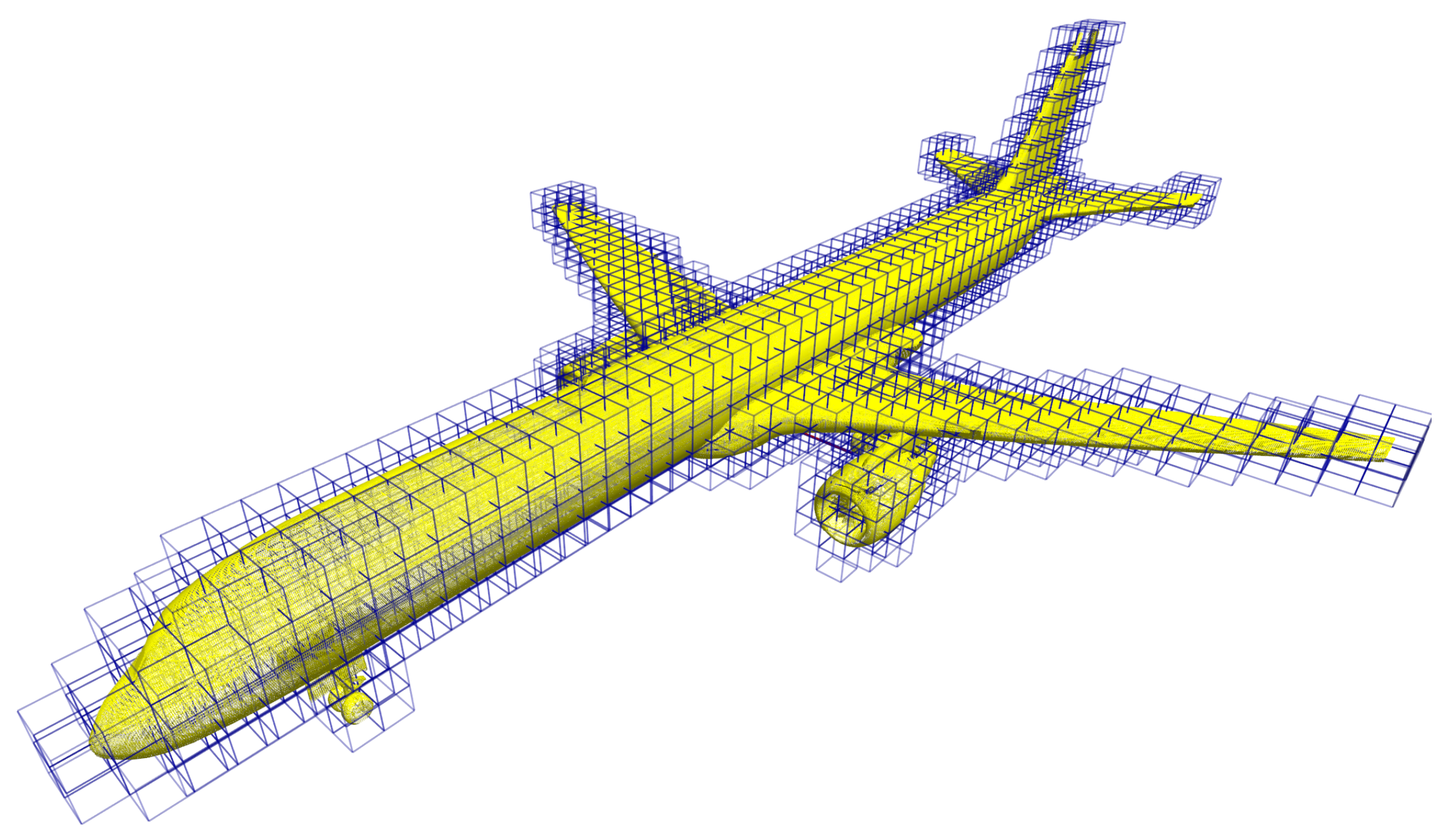
Taking the upper part of the fuselage as an example, based on the acquired coarse model of the aircraft in the first stage, 250 candidate viewpoints were generated with the working distance of 3.0 m from the aircraft surface and the voxel resolution of 1.0 m, as shown in Figure 8.
The algorithms were tested on a desktop computer with an Intel i7-8700 CPU, an Nvidia GeForce GTX 1070 GPU, and 32 GB memory. The combination of the SCP algorithm and the MMAS algorithm found a full-coverage scanning path consisting of 109 viewpoint frames with total length of 195.39 m, as shown in Table 1 and Figure 9a. Meanwhile, by considering six neighborhood viewpoints in the search, the MCTS algorithm found a scanning path consisting of 55 viewpoint frames with hyper parameters specified in Appendix B, and its total length is 152.37 m. The scanning path covers 85.89 % of the target area, as shown in Figure 9b. In terms of computational cost, the SCP and the MMAS algorithms took about 5 min to find the best path after around 550 iterations, while the MCTS algorithm took around 78 min for 1,000,000 iterations, which shows computational inefficiency, and this is a known issue of the MCTS algorithm with a large search space. However, the average frame coverage (the percentage of aircraft surface covered in one viewpoint frame) of the MCTS algorithm is 1.56%, which is better than the one of the SCP and MMAS algorithms (0.92%).
Increasing the number of neighborhood viewpoints will lead to more exploration in the MCTS algorithm, and thus require more computing resources. It is not a problem for an offline approach of planning the scanning path with a powerful computer; however, when the computing resource is limited or online path planning is required, reducing the number of neighborhood viewpoints is a simple way to reduce the learning cost and generate a scanning path more quickly, although the resulting path will be less optimal. In addition, increasing the terminated ϵ value will also result in more exploration in the MCTS algorithm, but the computed path will be more optimal. When the target area of interest is large and requires more viewpoints to cover, the solution found by MCTS tends to be less optimal; therefore, reducing the scope of search is a practical strategy in real-world aircraft scanning or inspection.
By following the planned scanning paths, the UAV–camera system can then perform close scanning to acquire a precise and dense digital model of the upper part of the fuselage, as shown in Figure 10a,b. The generated model following the scanning path computed by the combination of the SCP and MMAS algorithms covers the entire area of the upper part of the fuselage after 15 min flying. While it took around 9 min to scan by following the path computed by MCTS algorithm, the resulting model contains few gaps. This could be improved by using a camera with a larger FOV during the second-stage scanning. Another strategy to improve the MCTS coverage is to divide the large target area of interest into several smaller subregions, and solve the CPP problem for each subregion, as the MCTS algorithm tends to perform better for searching an area which requires less viewpoints to cover. An additional benefit of this strategy is that we could leverage multiple cheap UAV–camera systems to simultaneously scan the subregions, which further improves the efficiency of aircraft scanning and UAV’s common issue of short endurance.
In order to scan the aircraft, we divided the aircraft surface into several subareas so that the algorithms can compute a scanning path with higher coverage for each subarea. As the aircraft is symmetric, we computed scanning path on the left half of the aircraft surface, and mirrored the path to the right half of the aircraft surface. For scanning the belly of the aircraft, the viewpoints were generated at a safe distance of 2.0 m to the aircraft surface to ensure a feasible flying path for the UAV. By connecting all the path of subareas, the scanning path computed by the SCP and MMAS combined algorithm consists of 509 viewpoints with total length of 837 m, as shown in Table 2 and Figure 11. It covers 75% of the aircraft surface and requires around 59 min to complete the second-stage scanning. Meanwhile, the MCTS algorithm generated a path 689 m long which consists of 479 viewpoints and covers 68% of the aircraft, and the UAV needs to spend 53 min to complete the scanning. The second-stage scanning covers most of the surface of the aircraft body (excluding the landing gears and engines). The resulting dense models are shown in Figure 12.
During the digital experiment, we found that it is difficult to generate feasible viewpoints for the belly of the aircraft due to its confined space. In addition, the sharp features of wing edges may not be fully covered because the resolution for generating viewpoints is 1 m, which is relatively low for the sharp edges. In the future, we need to use a higher resolution to generate the viewpoints for the complex features around the aircraft wings and belly, which requires a close scanning on these areas in the first stage to generate more points for computing more accurate surface normal. Overall, the SCP and MMAS combined algorithm outperforms the MCTS algorithm in finding a scanning path for full coverage; however, the MCTS algorithm tends to find a path with less viewpoints, and thus requires shorter flying distance. Both methods can guide the UAV–camera system to scan the large aircraft within just one hour.
It is worthy of mentioning that in a physical experiment or application, the UAV–camera system operation may encounter potential issues such as malfunction, data lost due to bad communication network, large error in positioning due to imperfect configuration of the indoor GPS system, or dynamic obstacles such as a human entering the UAV’s workspace. All of these issues have not been covered in our study, but they must be addressed before a real flight test or practical use of the technology can be attempted.

6. Conclusions and Future Work

We developed a two-stage approach of a UAV-based 3D scanning system for exterior inspection or digitization of an aircraft. Such a created digital model can be used for detailed offline inspection, another downstream process in aircraft maintenance, such as visualization and defect analysis, or just for data capture for future reference. The UAV is equipped with a consumer-grade RGB-D camera and works with an indoor GPS system. The technology can significantly reduce human workload, eliminate human error, and improve work efficiency in scanning or inspecting an aircraft. It solved a CPP problem using an MCTS algorithm and an MMAS algorithm. Both algorithms can effectively find an approximate optimal path in terms of flying distance for automated full coverage scanning. This two-stage approach has been verified by dynamic simulation for scanning the upper part of an aircraft fuselage and the entire aircraft to quickly generate a dense digital model. Practical level of sensor errors and noise have been considered in the simulation tests. From the study, we found that the MCTS algorithm performs better in small search space than a large search space and, therefore, it is better to divide a large area of interest into several smaller areas before applying the MCTS algorithm. Such a divide-and-conquer strategy also possibly benefits using multiple UAVs to scan an aircraft simultaneously, which will be our future research. We also found that it is difficult to scan some belly areas of an aircraft using a UAV because the confined space poses a safety challenge to the flying UAV. Future research is needed to address this challenge.
The scanning work can be easily extended to aircraft online inspection, which requires a full coverage based on either a discrete or continuous path. Another future topic is to use a team of UAVs to perform scanning or inspection work, so that they can complement each other for team synergy and strength. The team can also be a combination of UAVs and UGVs because the UGVs tend to be more suitable than UAVs for scanning or inspecting the belly areas of an aircraft.

Author Contributions

Y.S. and O.M. conceived of the presented ideas. Y.S. implemented the software code and performed the simulated experiment. Y.S. took the lead in writing the manuscript. O.M. managed and advised the research, analysis, and documentation work of the project. All authors have read and agreed to the published version of the manuscript.

Funding

Yufeng Sun is supported by the UC Space Research Institute through a Graduate Research Fellowship.

Institutional Review Board Statement

Not applicable.

Informed Consent Statement

Not applicable.

Data Availability Statement

Not applicable.

Acknowledgments

This research was supported by the funding from the Space Research Institute of the University of Cincinnati.

Conflicts of Interest

The authors declare that they have no known competing financial interests or personal relationships that could have appeared to influence the work reported in this paper.

Appendix A. Characteristics of RGB-D Camera

Table A1. Sensor parameters.
ParameterValue
FOV ( H × V ) 69.4 ° × 42.5 °
Resolution (pixels) 640 × 480
Frame rate (fps)30
Depth range (m)0.15–10

Appendix B. Hyperparameters Used in MCTS Algorithm

Table A2. Hyperparameters in MCTS algorithm.
ParameterValue
Reward control parameter σ 0.9
Terminated ϵ 0.1
ϵ Decay rate0.99999
Maximum number of iteration1,000,000

References

  1. Drury, C.; Watson, J. Good practices in visual inspection. In Human Factors in Aviation Maintenance-Phase Nine, Progress Report, FAA/Human Factors in Aviation Maintenance; Applied Ergonomics Group Inc.: Williamsville, NY, USA, 2002; Available online: http://dviaviation.com/files/45146949.pdf (accessed on 20 February 2022).
  2. Donadio, F.; Frejaville, J.; Larnier, S.; Vetault, S. Human-robot collaboration to perform aircraft inspection in working environment. In Proceedings of the 5th International Conference On Machine Control And Guidance (MCG), Vichy, France, 5–6 October 2016. [Google Scholar]
  3. Miranda, J.; Larnier, S.; Herbulot, A.; Devy, M. UAV-based inspection of airplane exterior screws with computer vision. In Proceedings of the 14h International Joint Conference on Computer Vision, Imaging and Computer Graphics Theory and Applications, Prague, Czech Republic, 25–27 February 2019. [Google Scholar]
  4. Tzitzilonis, V.; Malandrakis, K.; Zanotti Fragonara, L.; Gonzalez Domingo, J.; Avdelidis, N.; Tsourdos, A.; Forster, K. Inspection of aircraft wing panels using unmanned aerial vehicles. Sensors 2019, 19, 1824. [Google Scholar] [CrossRef] [PubMed] [Green Version]
  5. Almadhoun, R.; Taha, T.; Seneviratne, L.; Dias, J.; Cai, G. A survey on inspecting structures using robotic systems. Int. J. Adv. Robot. Syst. 2016, 13. [Google Scholar] [CrossRef] [Green Version]
  6. Jing, W.; Deng, D.; Wu, Y.; Shimada, K. Multi-uav coverage path planning for the inspection of large and complex structures. In Proceedings of the 2020 IEEE/RSJ International Conference On Intelligent Robots And Systems (IROS), Las Vegas, NV, USA, 24 October–24 January 2020; pp. 1480–1486. [Google Scholar]
  7. Almadhoun, R.; Taha, T.; Dias, J.; Seneviratne, L.; Zweiri, Y. Coverage path planning for complex structures inspection using unmanned aerial vehicle (UAV). In Proceedings of the International Conference on Intelligent Robotics and Applications, Shenyang, China, 8–11 August 2019; pp. 243–266. [Google Scholar]
  8. Galceran, E.; Carreras, M. A survey on coverage path planning for robotics. Robot. Auton. Syst. 2013, 61, 1258–1276. [Google Scholar] [CrossRef] [Green Version]
  9. Wang, Y.; Chen, Q.; Zhu, Q.; Liu, L.; Li, C.; Zheng, D. A survey of mobile laser scanning applications and key techniques over urban areas. Remote Sens. 2019, 11, 1540. [Google Scholar] [CrossRef] [Green Version]
  10. Zollhöfer, M.; Stotko, P.; Görlitz, A.; Theobalt, C.; Nießner, M.; Klein, R.; Kolb, A. State of the art on 3D reconstruction with RGB-D cameras. Comput. Graph. Forum 2018, 37, 625–652. [Google Scholar] [CrossRef]
  11. Skorobogatov, G.; Barrado, C.; Salami, E. Multiple UAV systems: A survey. Unmanned Syst. 2020, 8, 149–169. [Google Scholar] [CrossRef]
  12. Mozaffari, M.; Saad, W.; Bennis, M.; Nam, Y.; Debbah, M. A tutorial on UAVs for wireless networks: Applications, challenges, and open problems. IEEE Commun. Surv. Tutor. 2019, 21, 2334–2360. [Google Scholar] [CrossRef] [Green Version]
  13. Bugaj, M.; Novák, A.; Stelmach, A.; Lusiak, T. Unmanned Aerial Vehicles and Their Use for Aircraft Inspection. In Proceedings of the 2020 New Trends in Civil Aviation (NTCA), Prague, Czech Republic, 23–24 November 2020; pp. 45–50. [Google Scholar]
  14. Sun, Y.; Zhang, L.; Ma, O. Robotics-Assisted 3D Scanning of Aircraft. In Proceedings of the AIAA Aviation 2020 Forum, Online, 15–19 June 2020; p. 3224. [Google Scholar]
  15. Norman, A.; Schönberg, A.; Gorlach, I.; Schmitt, R. Cooperation of industrial robots with indoor-GPS. In Proceedings of the International Conference on Competitive Manufacturing, Stellenbosch, South Africa, 3–5 February 2010; pp. 215–224. [Google Scholar]
  16. Wang, Z.; Mastrogiacomo, L.; Franceschini, F.; Maropoulos, P. Experimental comparison of dynamic tracking performance of iGPS and laser tracker. Int. J. Adv. Manuf. Technol. 2011, 56, 205–213. [Google Scholar] [CrossRef] [Green Version]
  17. Tao, F.; Zhang, H.; Liu, A.; Nee, A. Digital twin in industry: State-of-the-art. IEEE Trans. Ind. Inform. 2018, 15, 2405–2415. [Google Scholar] [CrossRef]
  18. Browne, C.; Powley, E.; Whitehouse, D.; Lucas, S.; Cowling, P.; Rohlfshagen, P.; Tavener, S.; Perez, D.; Samothrakis, S.; Colton, S. A survey of monte carlo tree search methods. IEEE Trans. Comput. Intell. AI Games 2012, 4, 1–43. [Google Scholar] [CrossRef] [Green Version]
  19. Stützle, T.; Hoos, H. Improving the Ant System: A detailed report on the MAX–MIN Ant System; Tech. Rep. AIDA-96-12; FG Intellektik, FB Informatik, TU Darmstadt: Darmstadt, Germany, 1996. [Google Scholar]
  20. Shen, Y.; Zhu, Y.; Kang, H.; Sun, X.; Chen, Q.; Wang, D. UAV Path Planning Based on Multi-Stage Constraint Optimization. Drones 2021, 5, 144. [Google Scholar] [CrossRef]
  21. Zhao, Y.; Zheng, Z.; Liu, Y. Survey on computational-intelligence-based UAV path planning. Knowl. Based Syst. 2018, 158, 54–64. [Google Scholar] [CrossRef]
  22. Zhang, H.; Xin, B.; Dou, L.; Chen, J.; Hirota, K. A review of cooperative path planning of an unmanned aerial vehicle group. Front. Inf. Technol. Electron. Eng. 2020, 21, 1671–1694. [Google Scholar] [CrossRef]
  23. Aggarwal, S.; Kumar, N. Path planning techniques for unmanned aerial vehicles: A review, solutions, and challenges. Comput. Commun. 2020, 149, 270–299. [Google Scholar] [CrossRef]
  24. Fendt, M. Airbus Launches Advanced Indoor Inspection Drone to Reduce Aircraft Inspection Times and Enhance Report Quality. Commercial Aircraft. 2018, Volume 10. Available online: https://www.airbus.com/en/newsroom/press-releases/2018-04-airbus-launches-advanced-indoor-inspection-drone-to-reduce-aircraft (accessed on 20 February 2022).
  25. Jing, W.; Polden, J.; Lin, W.; Shimada, K. Sampling-based view planning for 3d visual coverage task with unmanned aerial vehicle. In Proceedings of the 2016 IEEE/RSJ International Conference On Intelligent Robots And Systems (IROS), Daejeon, Korea, 9–14 October 2016; pp. 1808–1815. [Google Scholar]
  26. Bircher, A.; Alexis, K.; Burri, M.; Oettershagen, P.; Omari, S.; Mantel, T.; Siegwart, R. Structural inspection path planning via iterative viewpoint resampling with application to aerial robotics. In Proceedings of the 2015 IEEE International Conference on Robotics and Automation (ICRA), Seattle, WA, USA, 26–30 May 2015; pp. 6423–6430. [Google Scholar]
  27. Jing, W.; Deng, D.; Xiao, Z.; Liu, Y.; Shimada, K. Coverage path planning using path primitive sampling and primitive coverage graph for visual inspection. In Proceedings of the 2019 IEEE/RSJ International Conference on Intelligent Robots And Systems (IROS), Macau, China, 3–8 November 2019; pp. 1472–1479. [Google Scholar]
  28. Phung, M.; Quach, C.; Dinh, T.; Ha, Q. Enhanced discrete particle swarm optimization path planning for UAV vision-based surface inspection. Autom. Constr. 2017, 81, 25–33. [Google Scholar] [CrossRef]
  29. Silberberg, P.; Leishman, R. Aircraft Inspection by Multirotor UAV Using Coverage Path Planning. In Proceedings of the 2021 International Conference on Unmanned Aircraft Systems (ICUAS), Athens, Greece, 15–18 June 2021; pp. 575–581. [Google Scholar]
  30. Cabreira, T.; Brisolara, L.; Ferreira, P., Jr. Survey on coverage path planning with unmanned aerial vehicles. Drones 2019, 3, 4. [Google Scholar] [CrossRef] [Green Version]
  31. Kyaw, P.; Paing, A.; Thu, T.; Mohan, R.; Le, A.; Veerajagadheswar, P. Coverage path planning for decomposition reconfigurable grid-maps using deep reinforcement learning based travelling salesman problem. IEEE Access 2020, 8, 225945–225956. [Google Scholar] [CrossRef]
  32. Koubâa, A. Robot Operating System (ROS); Springer: Cham, Switzerland, 2017. [Google Scholar]
  33. Rusu, R.; Cousins, S. 3D is here: Point cloud library (pcl). In Proceedings of the 2011 IEEE International Conference On Robotics And Automation, Shanghai, China, 9–13 May 2011; pp. 1–4. [Google Scholar]
  34. Meyer, J.; Sendobry, A.; Kohlbrecher, S.; Klingauf, U.; Stryk, O. Comprehensive Simulation of Quadrotor UAVs using ROS and Gazebo. In Proceedings of the 3rd International Conference on Simulation, Modeling and Programming for Autonomous Robots (SIMPAR), Tsukuba, Japan, 5–8 November 2012. [Google Scholar]
Figure 1. Architecture of two-stage aircraft scanning system.
Drones 06 00087 g001
Figure 2. Octree representation of the coarse point cloud model of aircraft.
Drones 06 00087 g002
Figure 3. A viewpoint and its viewshed.
Drones 06 00087 g003
Figure 4. Examples of optimal scanning paths resulting from two different optimization techniques. (a) Scanning path found by the SCP and MMAS algorithms; (b) scanning path found by the MCTS algorithm.
Drones 06 00087 g004
Figure 5. Required number of iterations for different values of the hyperparameter σ .
Drones 06 00087 g005
Figure 6. Examples of optimal scanning paths on a large map. (a) Scanning path found by the SCP and MMAS algorithms; (b) scanning path found by the MCTS algorithm.
Drones 06 00087 g006
Figure 7. Digital experiment environment. (a) Boeing 757 mesh model; (b) quadrotor with an RGB-D camera.
Drones 06 00087 g007
Figure 8. Candidate viewpoints of the upper part of the aircraft fuselage.
Drones 06 00087 g008
Figure 9. Examples of scanning paths for the upper part of the aircraft: (a) A scanning path found using the SCP and the MMAS algorithms; (b) a scanning path found using the MCTS algorithm.
Drones 06 00087 g009
Figure 10. Dense models generated in the second-stage scanning. (a) Dense model generated using the SCP and MMAS algorithms; (b) dense model generated using the MCTS algorithm.
Drones 06 00087 g010
Figure 11. Scanning paths for the aircraft. (a) A scanning path found using the SCP and the MMAS algorithms; (b) a scanning path found using the MCTS algorithm.
Drones 06 00087 g011
Figure 12. Dense models of the aircraft generated in the second-stage scanning. (a) Dense model generated using the SCP and MMAS algorithms; (b) dense model generated using the MCTS algorithm.
Drones 06 00087 g012
Table 1. Computed scanning paths.
AlgorithmCoverage
Ratio (%)
Frame
Count
Computational
Cost (min)
Path
Length (m)
Coverage
per Frame (%)
SCP+MMAS1001095195.390.92
MCTS85.895578152.371.56
Table 2. Computed scanning paths for entire aircraft.
AlgorithmCoverage
Ratio (%)
Frame
Count
Path
Length (m)
Scanning
Time (min)
SCP+MMAS7550983759.7
MCTS6847969853.2
Publisher’s Note: MDPI stays neutral with regard to jurisdictional claims in published maps and institutional affiliations.

