Article

Inverted Docking Station: A Conceptual Design for a Battery-Swapping Platform for Quadrotor UAVs

by
Sudam Chamikara De Silva
1,
Maroay Phlernjai
1,*,
Suchada Rianmora
1 and
Photchara Ratsamee
2
1
School of Manufacturing Systems and Mechanical Engineering, Sirindhorn International Institute of Technology, Thammasat University, Pattaya 12120, Thailand
2
Cyber Media Center, Osaka University, Osaka 567-0047, Japan
*
Author to whom correspondence should be addressed.
Drones 2022, 6(3), 56; https://doi.org/10.3390/drones6030056
Submission received: 30 January 2022 / Revised: 16 February 2022 / Accepted: 19 February 2022 / Published: 23 February 2022
(This article belongs to the Special Issue Conceptual Design, Modeling, and Control Strategies of Drones)

Abstract

:
“Flight Time” and the “Scope of the mission” play major roles in using UAVs as they affect most industrial activities. Once the battery has depleted, the UAV has to land on the ground and human interaction is needed to change the battery with a fully charged one. Nowadays, several automatic battery swapping systems are catching interest in research. This research presents the novel concept of an Inverted Docking Station that allows a quadrotor UAV to attach to the ceiling during the automatic battery-swapping process. The proposed design consist of a docking station, a positioning system and gripper mechanisms. The proposed design allows the quadrotor to carry the load under the quadrotor and remain attached throughout the servicing period. A mathematical model and design guideline have been proposed, and a Finite Element Analysis (FEA) was performed to check that the developed platform is strong enough to withstand the above task. A ‘DJI TELLO’ small-scale quadrotor was chosen as a case study to demonstrate the proposed research. Finally the advantages and the limitations of the system are discussed.

1. Introduction

The flight time of Unmanned Aerial Vehicles (UAVs) becomes a major issue when considering the drawbacks of drones. This is due to the battery power of the drone, as it cannot provide enough power to contribute to longer-length missions such as surveillance, wildlife monitoring, and remote GIS applications [1]. Nowadays, most of the industries using drones use Li-Po batteries. These types of batteries usually provide a maximum of 30 min charge for a single drone cycle [2], depending on the specifications of the drones, sensors and actuators. Generally, it is known that charging a Li-Po battery will take around 1–2 h. So, the mission time will be directly affected if the batteries of the drones need to charged every 30 min. Battery swapping will take significantly less time than charging at the cost of a usually tedious manual operation and the need for more battery units in reserve [3]. To solve the insufficient power issues of the UAVs, several battery-charging stations or battery-swapping stations have been proposed. A battery-charging station can be a wireless charging system [4,5,6,7,8] or a wired charging dock [9,10,11,12,13,14] to charge the installed battery after the UAV lands on the docking station. In some cases, in-air charging facilities which use Photo Voltaic (PV) cells were attached to the UAV [15]. For automatic battery-swapping stations [16], after the UAV lands, the UAV is positioned in a manner that a robotic gripper can be used to properly swap out the used battery with a fully charged one. Usually, the swapping stations require the UAV to land with higher accuracy and therefore need a positioning system to help align and immobilize the drone during the swap [17]. Many positioning, charging, and swapping systems have been suggested and will be reviewed in detail in the literature review section.
Currently, battery-swapping systems require battery-swapping stations to be situated on the ground. However, when the drone is a “Package Delivering” drone, which carries the package under its body, it is required to unload the package first and then re-load the package after the battery is swapped [18]. Therefore, we may need another kind of system to load and unload the package. Rather than making such a system, in this paper, a new docking technique is to be implemented instead, as shown in Figure 1, and the novel concept of an “Inverted Docking Station” will be proposed to swap the battery of a quadrotor UAV which has inversely landed, as in Figure 2. It is advantageous to implement such mechanism as the goods do not need to be unloaded nor the package delivered before the battery is swapped. Overall, the research gap and contribution of this paper are summarized as follows.
Research Gap: A range of research on UAV docking stations has been focused around a ground-based docking concept. There is a research gap in the area of inversely docking the UAV, which allows battery swapping while carrying the load. In addition, to the best of our knowledge, a design guideline for a w-shaped positioning plate has not been presented before.
Contribution:
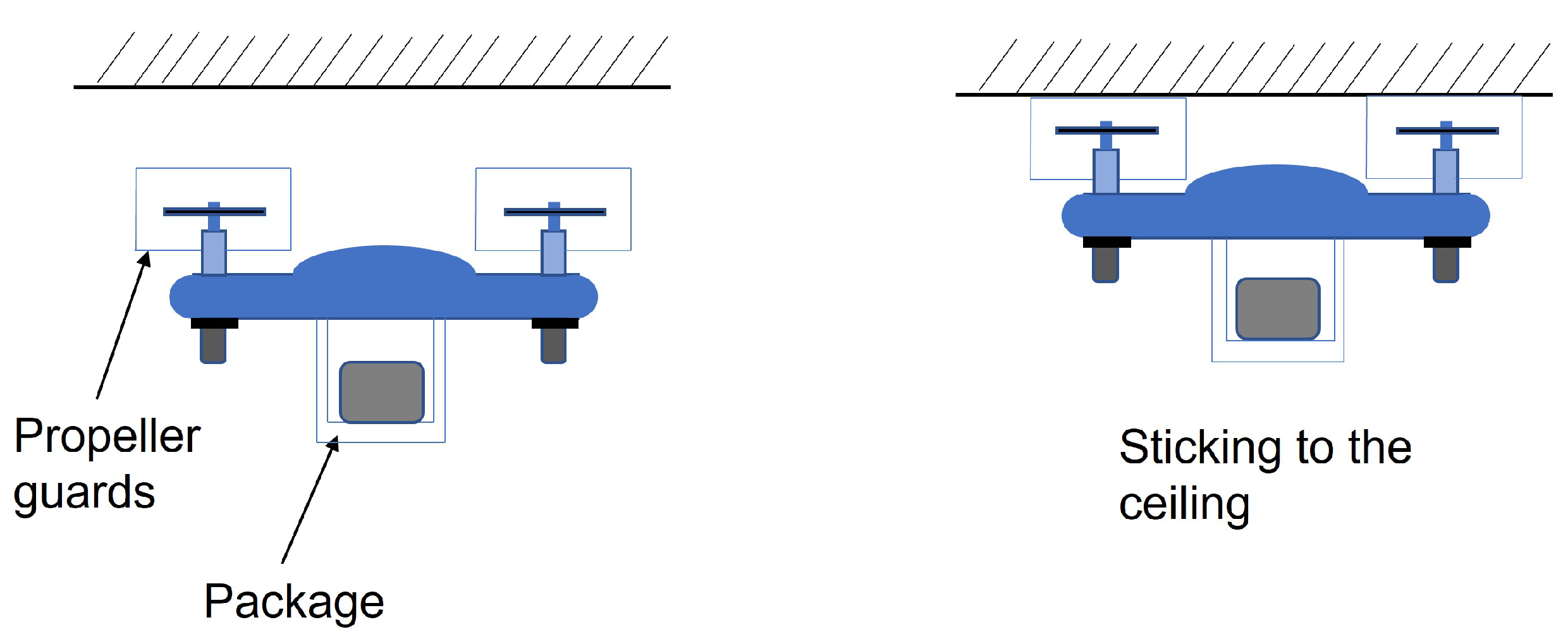
  • Propose a novel concept of inverted docking;
  • Present design guidelines and a mathematical model of a w-shaped positioning design for quadrotor UAVs with experimental landing error data;
  • Develop a 3D CAD model of the inverted docking station with detailed motion steps;
  • Simulate a motion study and Finite Element Analysis (FEA) of the designed 3D model.
The structure of the paper is as follows: existing battery-swapping systems and related designs will be discussed in Section 2; Section 3 will present the details of the inverted docking concept; Section 4 will present the design; Section 5 will show motion simulation with a CAD model; Section 6 will show the Finite Element Analysis (FEA) simulation results with discussion; and, finally, Section 7 will conclude the study.

2. Literature Review

To overcome this issue of battery life, researchers have already proposed several solutions. These approaches may be aimed at improving the power supply by including the development of batteries with high power density, hydrogen fuel cells, internal combustion engines, and solar panels. Generally, these power supplies can be divided into two categories, the generator type and energy-storage type. Generator-type power supplies will generate the required power on the fly, while energy-storage devices will provide the stored power to the drone. The energy-storage devices need to be recharged after they become depleted. [2,19].
The generator-type power supplies in UAVs provide a much higher energy density, so drones are able to have a much longer flying cycle [20]. In contrast to the generator type, energy-storage-type power sources are reliable for use with drones. However, commonly used Lithium Polymer (Li-Po) and Lithium Iron (Li-ion) for UAV greatly limit the flight time. When considering the power density of those two types of batteries, Li-Ion batteries will provide a much higher power density than the Li-Po batteries. However, when considering the size of the battery, much larger, so Li-Po batteries are used for most kinds of UAVs [21,22].
As the limited battery life of a UAV is a huge obstacle for many missions, drone battery-charging docks have been implemented [23]. In this study, these methods will be introduced and discussed showing the superiority of the “Battery Swapping Station” over other mechanisms. Normally, this kind of battery-swapping station contains two main parts, known as the “Landing and positioning Mechanism” and the “UAV Charging mechanism” [24].

2.1. Landing Platforms of UAVs

“Landing platforms” have been designed for the tasks of loading and unloading goods and packages, battery refiling/replacement, data exchanging, etc. [25]. To achieve the above tasks, precision landing is needed. Precision landing is difficult due to meteorological conditions and visibility. This means meteorological conditions, such as fog or dust storms, as well as the visibility conditions, such as low light, will affect the landing precision.
When paying attention to the landing mechanisms, there may be cases that the UAV has to land on to a fixed landing platform as well as a mobile platform. In [26], a novel method was proposed to develop a robust controller to land the drone on a sloped platform. There, they proposed a hybrid automation model which pivots a quadrotor through a slope. In [27], a method that used the “velocity vector field method” was implemented. These two methods have been separately implemented for fixed-wing type UAVs and rotary-wing type UAVs. There, the study was a remarkable one, as it needs only the relative position between the landing platform and the drone. In most cases, researchers use vision-based sensing methods to detect the exact landing position [28]. Further, the above method was developed to detect the differential kinematic of the UAV and to detect a reference speed and an image of the UAV [29].
Normally, the “Ground Effect” will act on the UAV to deviate that from a precise landing position. The ground effect induces perturbations of in-flight stability when the UAV operates near the ground [30]. Moreover, turning off the propellers of the UAV after the landing may cause the UAV to deviate from the exact position of landing when subjected to windy conditions.
The landing platforms can be divided into two main parts: the first have positioning devices and the second do not. In the next subsection of the study, it is important to have an idea of the positioning mechanisms used in UAV landing platforms.

2.2. Positioning Mechanisms

These types of positioning methods can be divided into two main categories: (a) active positioning methods, and (b) passive positioning methods. For the active positioning methods, single or several control methods and actuators may be used. In contrast, for the passive positioning methods, no such methods will be used, only gravity.

2.2.1. Active Positioning Mechanisms

Normally, active positioning techniques will use actuators to position the UAV and a specific locking will happen there. At a glance, the pros and cons of all the types of UAV active positioning mechanisms in landing platforms can be seen in Table 1.
In [31,32], an autonomous parallel position mechanism was used to position the UAV to the center position by activating the pushers synchronously. The importance of using this kind of positioning mechanism is that it can be used for a wide range of UAV sizes and the final position is not limited to just the center but is also adjustable by control of the parallel plates. On the other hand, it requires two actuators to activate. Moreover, a special control scheme is needed if the UAV has nonsymmetrical leg structure, such as a non-even number of legs. Several studies were conducted to improve those multipushing mechanisms to reduce the number of pushers. In [33,34], a w-shaped centering system for the positioning of a quadrotor was developed. As the two positioning plates clamp in, the UAV is positioned in the center position as it slides along the “V or W-shaped walls” of the positioning plates. The advantage of this method is that it only requires a single actuator to operate. In addition, the electrical contacts can be installed at the inner corners of the w-shaped plate, allowing wired charging and data transfer if needed. The disadvantages are that it cannot freely adjust the final UAV position other than the center and there is a lack of a clear design guideline for the w-shaped plates. Another type of active positioning mechanism is “Rotating positioner”, which aligns the UAV by means of rotating the legs around [35]. In this design, the mechanism can be easily activated by simple rotation, but the fixing of the UAV is looser than the previously mentioned parallel and w-shaped positioning mechanisms. Lastly, an innovative design based on “Iris diaphragm” was developed in [36]. This design can accommodate a wide range of UAV sizes with simple control. However, the complexity of the assembly and lack of orientation lock of the UAV are factors that need to be considered.

2.2.2. Passive Positioning Mechanisms

On the other hand, for passive positioning methods, it is known that the UAV will be positioned using passive interaction and movement in horizontal and vertical directions. Studies have implemented a gravitational-based positioning for UAVs by using “conical funnels”. In the study done in [37], a landing platform for the UAV was implemented using a “funnel-shaped” centering housing. This method was in correspondence to the plurality transformation of the UAV. Further, the system was accomplished with a serial data-transfer-method-based battery-recharging mechanism. In the study of [38], a three-phase power wireless charging unit was implemented and the funnel-based positioning mechanism was used. Further, the funnel consists of a wireless charger. In the study done in [39], funnels were divided into horizontal tires so that they will fold when the drone legs passed those tires. This will lead the UAV to stop at a required height so that the payload on it will be reduced. Normally this type of funnel positioning can be divided into three main categories as the UAV can be landed on funnels with respect to each of the legs; a single funnel for each of the legs or a single conical funnel for the drone body. Recently, in [40], a “Drone Fixing mechanism” was implemented conceptually to create a power station for the drones. Additionally, a cone-shaped landing platform was conceptually designed to position the drone by gravity. Rather than standing by the legs on a funnel, this research work proposed a hanging mechanism to position the UAV in a funnel. For this design, cone-like equipment was oriented in an upside-down direction. There, the drone consisted of a reattachable hanging device. The design was implemented as follows: when the UAV is tilting towards the center of the guide, the UAV will be moved in an upward direction. Nowadays, there are commercially available platforms that can land all the UAV legs in a one conical shape funnel. The UAV legs were made with bevel-shaped frames so that a better landing could happen. At the same time, there are positioning mechanisms where the landing platforms use “Ski-Type Legs”. Positioning happens either after landing the UAV or while the UAV is landing.
Table 2 shows the pros and cons of the “Passive” positioning mechanisms used in UAV landing platforms. The following information in Table 3 can be identified as the common pros and cons for all the types of positioning mechanisms in both types of landing platforms.

2.3. Battery-Charging Techniques for UAVs

Batteries have been used as the electrical power source of UAVs. In order to operate UAVs continuously within a given operation, the batteries should be either charged or replaced. In this section, UAV-charging techniques which have been done without human intervention are discussed. These charging techniques can be divided into two main parts: wired charging techniques and wireless charging techniques. In [10], a charging station was designed specifically for surveillance UAVs. The proposed system has a multiple-UAV-charging ability. However, some drawbacks such as short circuit problems have been identified. In contrast to the previous research, a mobile UAV-charging platform was developed in [11]. A separate navigation system was implemented as it needs to have a better controlling precision between the platform and the UAV. Further, the short circuit issues were eliminated by adding a separate fuse to the platform. In [12], a charging pad was developed for quad rotor UAVs, as the four legs of the UAV connected with the battery and the charger wires. An automata-based technique was implemented in [13] to develop the UAV charging platform, where it handles multiple UAVs without collisions. Further, in [14], economical consumption of the UAV charging stations, with respect to the terminal connection, modularity, complexity, and cost, was analyzed. Several wireless charging techniques have been used in order to charge UAV batteries. In [5], an indoor wireless charging platform was developed which has 50% of the power transfer efficiency of a typical WPT. Further, in [6], the above research was extended to achieve 75% power transfer efficiency by adding more transmitter and receiver coils to the system. In [7], asymmetrically coupled coils were used to make a system with WPT. The system optimized the coupling distances and the charging was varied accordingly. Further, in [8], a station based on magnetic resonance connections was implemented conceptually. There, the transmitter and receiver coils had the capability of aligning to an optimum position so that the charging efficiency was high. In contrast to all these, an air bone charging and docking technique has been implemented in [42].

2.4. Battery-Swapping Stations for UAVs

Turning to UAV technology, a battery change/swap will be needed as it will become depleted after a certain flying cycle. To change these batteries, we may need a battery-swapping mechanism with a gripper. There are two types of battery swapping procedures used in battery-swapping stations, known as “Hot battery swapping” and “Cold battery swapping”. When the battery swapping happens, the drone power will be disconnected when the battery taken out. However, the battery swapping can be performed with this condition as it will be the major task. This is called “Cold battery swapping” in the industry. In contrast, backup power can be given to the UAV while battery swapping happens. This will be a good solution to keep the real-time data that has been stored with the non-versatile memory of the drone. Scientifically, this is called “Hot battery swapping”.
In [43], an autonomous battery-swapping system was implemented. The system consists of a dock and station for battery swapping. A specific camera module with an IR beacon was used to perform the task accurately. The system was able to handle up to six batteries and improve the safety of the system in weather conditions such as flooding and sunlight. On the other hand, in [44], an automatic multi-rotor refueling system was developed with a “Hot battery swapping” ability. Overall, the abovementioned system can handle up to four batteries; three of them are already charged and the remaining is depleted. Another work in [45] has the capability of hot battery swapping and handling up to eight total battery buffers. Further, this system could enable fast hot battery swaps to ensure the success of long missions. In “Automatic Battery Replacement System for UAVs: Analysis and Design”, a battery-swapping platform was developed which covers the operation of handling a heterogeneous UAV fleet [46]. In [47], research was performed to develop an autonomous battery maintenance mechatronic system that significantly increases the operation time of UAVs. There, the depleted battery of the UAV is swapped with a replenished one, while the system offers a recharging facility for several other types of batteries. In this study, the recharging time and the battery queue time were allocated so that a UAV can receive a completely recharged battery. Moreover, a shore-power was provided to the UAV by a servo mechanism to achieve hot battery swapping.
On the other hand, DIY Drones in Denmark implemented an Automated Mind storms Battery-Swapping station for UAVs. There, a rod is responsible for taking the depleted battery from the UAV and swapping it with a charged battery while the UAV slides through a roller. Further, a conceptual design for a small-scale power station for UAVs was implemented that has the capability to load and unload up to six batteries. The designer aims to reduce the errors and stress of workers in battery-swapping stations.

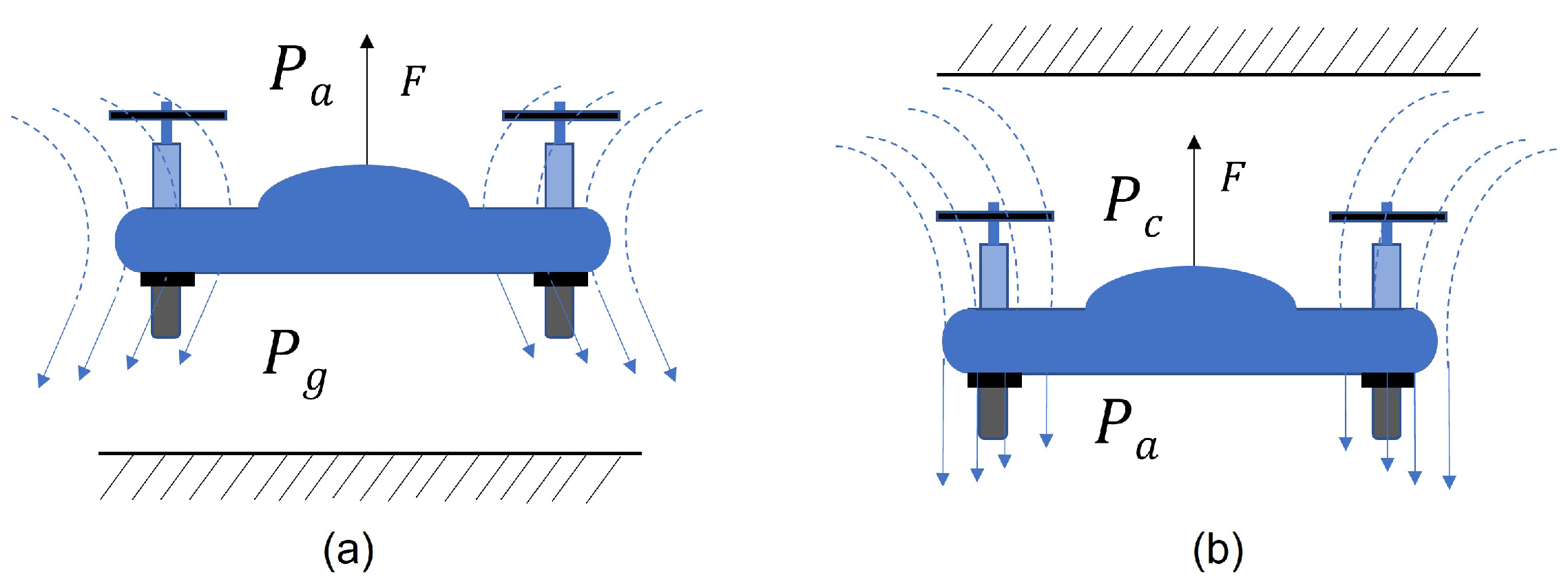
2.5. Ground and Ceiling Effects

Paying attention to UAVs, two important effects, “Ground effect” and “Ceiling effect”, should be taken into account. Simply, “Ground effect”, as illustrated in Figure 3a, affects the accuracy of the UAV landing when it flies near the ground. Ground effect is known as an enhancement of the force performance when a UAV flies near the ground [30]. In this case, P g denotes the pressure near to the ground and P a denotes the air pressure. When the UAV flies near to the ground, P g > P a , meaning there will be a cushioning effect on the UAVs.
This ground effect depends on several factors such as wingspan, chord length, angle of attack, flying speed, and wing loading factor [48]. Normally, research has been done based on the on-ground battery-swapping mechanisms. The “Ceiling effect” will affect “Multi-rotor copters” when they perch under the ceiling. As illustrated in Figure 3b, the spinning propellers of the copter will produce a pressure difference and the ceiling will disrupt the upstream wake [49]. In this case, P c represents the pressure near to the ceiling and P a represents the air pressure. It is known that P a > P c , so a pressure difference will occur. Due to this pressure difference, propellers will be attracted to the surface because of an aerodynamic force, and the copter will stick to the ceiling.
In the research carried out in [50], it was experimentally illustrated that the thrust force generated by the propeller of the drone will be increased when the propeller moves closer to the ceiling. On the other hand, the input power will remain unchanged, so that the power consumption will be much higher when the drone flies near to the ceiling. In such a case, it is understood that the battery power of the drone will rapidly decrease when it flies near to the ceiling. On the other hand, it was pointed out that the controller of the drone should be able to deal with a ceiling approach, as it should not bounce when it reaches to the ceiling. Further, the altitude and spatial stability should be retained in order to have proper contact with the ceiling. Considering all these criteria in landing and positioning mechanisms, ground effect and ceiling effect, our conceptual design will use the ceiling effect on a “quadrotor” which will stick to the ceiling so that battery swapping can be carried out using the proposed inverted docking station rather than using a typical docking station.

3. Concept of Inverted Docking Station

To develop the inverted docking station, the landing should be an inverted one, i.e., it will not land on the ground. Whenever the UAV needs to be recharged due to depletion of the battery, a specific message will be delivered to the pilot and the pilot will start to land the UAV for battery swapping. In contrast to a ground landing, a quadrotor UAV will stick to the ceiling first. After that, the UAV will be precisely positioned and will lockto the edges of the plate. Next, the battery swapping will happen. Finally, the UAV will continue its operation/mission. Figure 4, shown below, illustrates the idea which is explained above. Here, a propeller guard which covers the top area of the DJI TELLO propellers was selected. It is important to have a propeller guard which covers the area above the propeller, since hitting the ceiling with propeller would cause damage to the propeller and disrupt the ceiling effect acting on the UAV.

3.1. Overview of the Research

In this section, attention will be paid to the overall activities which are accomplished via the research objectives and also via the main tasks. The overall activities can be identified as the following.
  • Calculating the error of landing;
  • Designing the landing platform and the positioning mechanism based on the calculations;
  • Analyzing the gripping mechanism to achieve the loading and unloading of the battery from the quadrotor;
  • Creating a customized secondary gripping mechanism to change the orientation of the battery;
  • Identifying design limitations.;
  • Preparing a movable battery charging unit.

3.2. Scope of the Research

To develop the overall platform of the battery-swapping system, the quadrotor UAV model “DJI TELLO” is to be used. A w-shaped moving mechanism for the quadrotor to a specific orientation will be implemented to position the UAV. To land the quadrotor, a message should be received by the drone pilot, so a mobile-based application can be used for that. The battery-swapping part will be implemented with a robotic gripper and motor-controlled gripper positioner. The scope of the research can be summarized as follows.
Size of the UAV: The type of UAV used for this research was the ‘DJI RYZE TELLO’ model with a weight of 80 g without a payload and the dimensions were 98 × 92.5 × 41 mm. A 3D model of TELLO is shown in Figure 5. The DJI TELLO model was selected for this as a case study, due to its availability in the market and was used purely for the research purpose.
The Inverted Docking Location: We proposed a novel under-the-ceiling landing method. The inverted docking concept will be demonstrated with a model table-shaped docking platform with a height significantly greater than the default take-off height of the chosen UAV model (DJI TELLO).
The Docking Error Experiment: The selected UAV will be tested for its real data on how much it deviates from the center of the docking point. This docking error does not indicate the poor capability of the UAV, but is rather presented as a way to generalize a design guideline of the w-shaped positioning mechanism. It should be noted that all experiments were carried out in an indoor environment with no external wind conditions; also, no localization technique for docking was used to increase the docking accuracy.
Battery Characteristics: an FRSDG rechargable Lithium-ion 3.8 V 1100 mAh battery was used for the operations of the abovementioned DJI TELLO drone. The battery contains four charging terminals known as (+)ve terminal, (−)ve terminal, and two BSI terminals.
Battery-Swapping Mechanism: The design scope for the battery swapping is to be used with 2 simple pnuematic grippers: one mounted on motor-controlled sliding rails, and another working as a secondary gripper to rotate the gripping orientation of the battery to fit in a market-available charger. While designing our own battery charger is possible, this research focuses more on delivering the new concept of the inverted docking station.

3.3. Design Considerations and Guidelines

3.3.1. Error of Inverted Landing

Error of the inverted landing can be defined by conducting several trials of quadrotor UAV docking under-the-ceiling. Figure 6 shows the experiment settings. First, the UAV is positioned directly under a test table. Then, the UAV takes off vertically and is controlled to slowly ascend until it is firmly attached to the bottom surface of the table. The final attached position of the drone is recorded by a camera and compared to a perfectly precise position of the UAV marked under the test table. After analyzing the results of the landing, it was identified that the UAV rotated from the precise landing position as well as becoming offset from the position as in shown in Figure 6. The radius of the center shift (r) and the angle of rotation ( θ ) were measured. This procedure was repeated 10 times. Points p 1 , p 2 , p 3 , and p 4 denote the positions of each leg. Due to the center offset and rotational error given above, point p 1 is translated to p 1 and rotated to p 1 c c w , respectively. Table 4 shows the experimental data. The center of the UAV is assumed as the origin of the coordinates.
Variables r and θ shown in Figure 6 are the radius of shift and the angle of rotation respectively. Further, it was assumed that the angle of rotation in clockwise direction is (-) and counterclockwise direction is (+).
It should be noted that the above deviation of landing was measured without applying any localization technique to improve the landing accuracy. The authors do not intend to generalize the landing error data as a limit of the capability of the TELLO model.

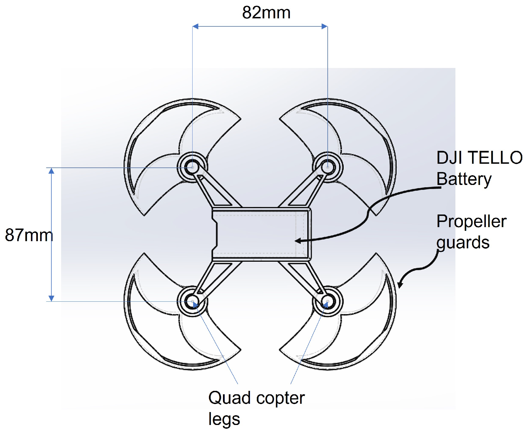
3.3.2. Designing the Positioning Plate

When considering the positioning of a quadrotor, w-shaped positioning plates have an advantage in that they can constrain the UAV and properly clamp its leg with fewer actuators compared to other positioning types as discussed in the literature review section. However, proper control strategies are needed and the UAV should land within the error range where the legs can be properly grasped within the slopes of w-shaped plates.
Let us imagine that the drone legs have been in contact with the w-shaped positioning plate walls as in Figure 7.
Here, F P and the F P are known as acting forces from the positioning plate to the UAV legs. When assuming translation of the drone legs along with this positioning mechanism, the two forces F X and F X should be equal. Designing the depth, angle, and width of this positioning plate plays an important role in this task and is greatly dependent on the UAV’s size. In general, minimum sliding friction would be beneficial for the position performance and a steeper angle θ should be preferable. However, adjusting the angle will also affect the acceptable UAV size of the plates.
In this paper, we now propose a generalized method to design a w-shaped positioning plate given the data on the landing error and the UAV size. When designing this kind of positioning plate, the following points should be clearly identified for a proper positioning.
  • UAV size measured from the leg centers l d , w d ;
  • Possible landing position of the legs;
  • Width of the positioning plate w;
  • Depth of the positioning plate d.
Given that DJI TELLO was chosen as the case study, the drone size is shown in Figure 8.
As for the possible landing position of the leg, we can calculate this based on the error of inverted landing acquired from the experiment in Section 3.3.1. According to Table 4, average values for the radius of shift and angle of rotation were identified as 30.3 mm and 6.6 degrees, respectively. Assuming this angle of error could occur in both the clockwise and counterclockwise directions, a mathematical simulation has been carried out to illustrate the possible landing area of each leg. Figure 9 shows the simulation results using the DJI TELLO model. The figure is generated by sweeping the arc p 1 c c w p 1 c w around the circumference of the center shift circle with radius r. The resulting swept area determines the possible leg position based on extreme center shift. Note that in the actual scenario when the UAV center shift is less than r, the outline of the swept areas can still provide an illustration to all the possible positions based on the experimental data. Therefore, the top and bottom extremes of each leg area can be used to design a proper width of the positioning plate as follows. Given this, there is no overlapping of areas among different legs.
w > ( l d 2 + w d 2 ) sin θ cos β + 2 r
β = arctan ( l d w d )
Next, the depth of the positioning plate can be determined by considering the clamped state of the quadrotor as shown in Figure 10. The general idea is that the greater the depth is, the smaller the slope angle α which affects the sliding friction along the w-plate. Therefore, a higher depth d is preferable in most cases. However, there is a limitation due the physical contact between the plate and the UAV body.
The depth d has to be less than a certain value as to avoid two plates colliding during the clamping procedure. This can be written as follows.
d ( w d t ) 2
The slope angle α is related to the designed value of the width w and the depth d of the positioning plate.
α = arctan ( w / 2 ) d
A general design guideline for this w-shaped plate is
  • Choose proper width w according to landing errors;
  • Choose plate angle α as small as possible to reduce contact friction;
  • Check the depth d to prevent collision.
Using the proposed guideline, the condition for the width (w) was w > 63.5 mm, and we chose an angle α of 60 degrees to make sure the plates did not collide when clamped to the UAV. Figure 11 shows the designed w-shaped position plate for the system.

3.3.3. Analyzing the Gripping Mechanism

The gripper in engineering is used as a method for material handling [51]. In this study, the gripper is remarkable as it can both load and unload the battery. It was determined that the automated gripping mechanism must be the same as the manual operation when the battery is gripped. To achieve optimum battery grip in the system, a two-way battery gripping is required, as first the gripper will detach the battery and then it will grab the battery.
The same operation can be used to insert the battery into the battery cage. However, the battery needs to be locked after being inserted into the battery cage of the drone. Figure 12 shows this operation.

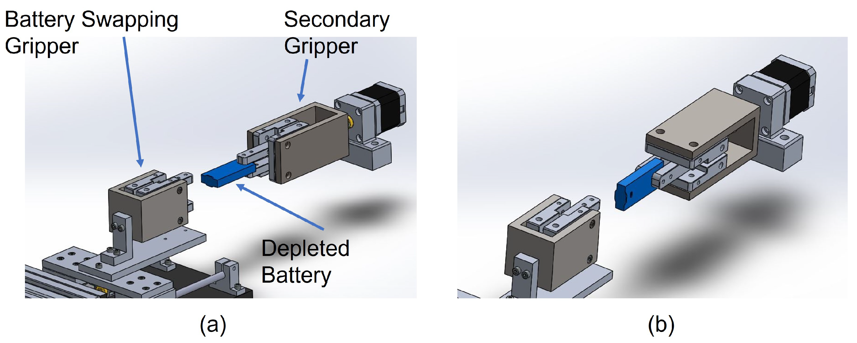
3.3.4. Need of a Secondary Gripper

In this system, a market-available drone battery charger was used for the charging process of the depleted battery. It was determined that the gripper jaws of the battery-swapping gripper should hit the battery in the charger when the battery-swapping operation happens continuously. Figure 13 describes this situation.
To overcome this issue, either the battery orientation should be changed or the battery charger orientation should be changed, as in Figure 14. However, the battery orientation cannot be changed as it is fixed to the drone. Although the battery charger changed its orientation, the battery orientation also needs to be changed, since it is a fixed one for the quadrotor UAV model.
For this case, a secondary battery gripper is needed to change the orientation of the battery, as Figure 15.

3.4. Definition of Working Sequence for the System

  • Docking: The UAV is inversely docked under the ceiling with the help of the ceiling effect;
  • Positioning: The UAV is then centered and locked by w-shaped positioning plates;
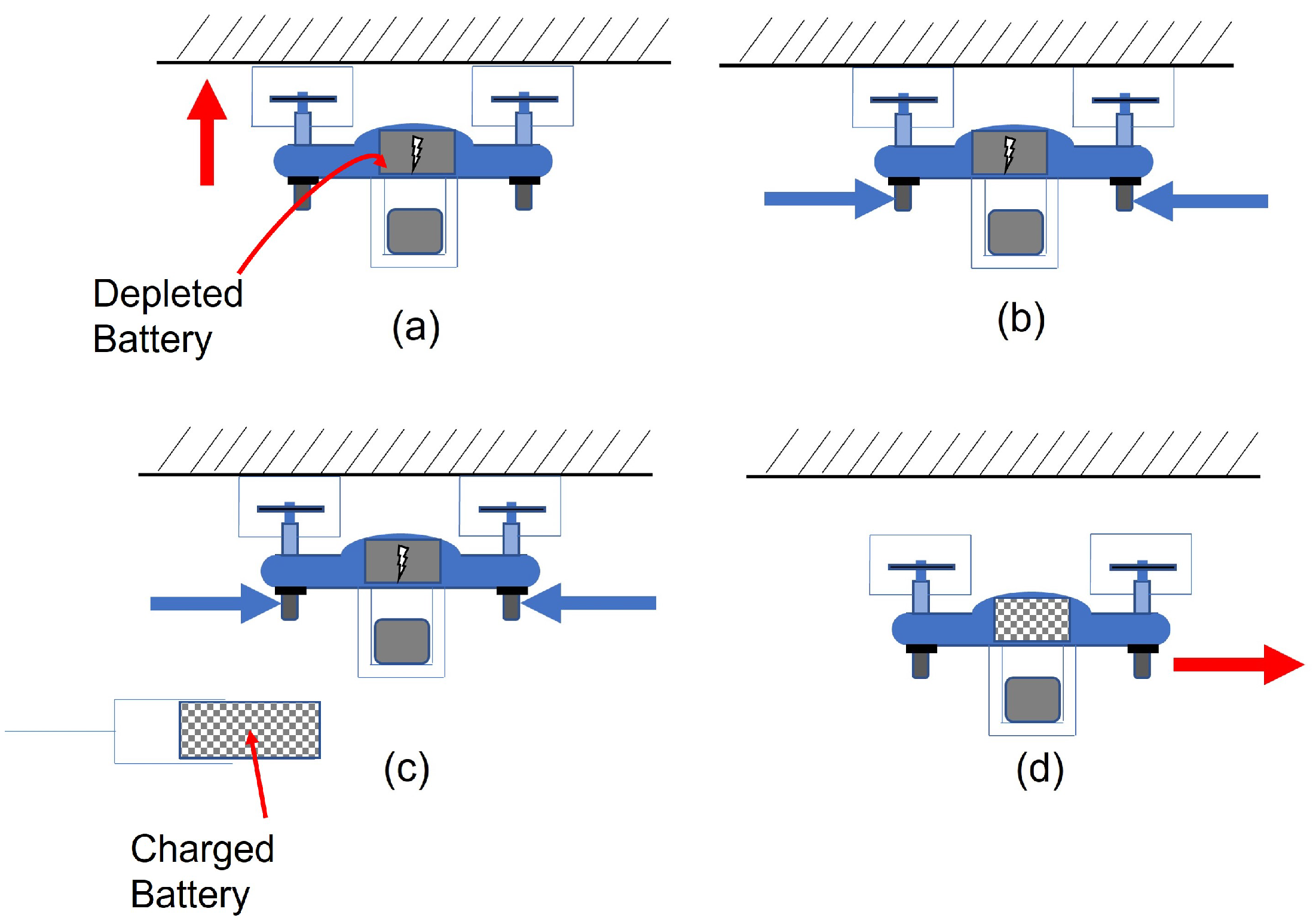
  • Battery swapping: The depleted battery should be removed, and a new battery is installed by the battery-swapping gripper;
  • Unlocking: The positioning plate releases the UAV from its locked position;
  • Flight: The UAV is now free to fly out from the station.
The above steps have been simulated, and more detailed steps are shown in Section 5.

4. Design of the System

When designing the above system, the design engineer should have certain concerns, such as cost-effectiveness, ease of dissembling, and ease of assembling. The proposed design of the battery-swapping system can be separated into three main groups: the landing and positioning platform; the battery-gripping platform; and the battery-charging platform, which is illustrated in Figure 16. In this section of the study, the material selection and other specific details of the above groups will be discussed.

4.1. Designing of the Landing Platform and Positioning Mechanism

As the process of replacing or swapping the depleted battery is the main purpose of the system, first it needs to land the quadrotor UAV. To do this, it needs to understand whether the drone will invert dock or not at the initial location within the area of interest. In this system, the goal is to stick the DJI TELLO quadrotor to the ceiling. Normally, the room ceiling height will be 2.7 m, but it is challenging to conduct the servicing at such height. In this case, the height needs to be reduced, and the flat area under a table-shaped structure should be used as the “ceiling”. In our design, the inverted landing height was chosen to be 1.8 m, as it was observed that the DJI TELLO quadrotor will hover at a height of 0.9 m when it powers up. Considering this criteria and the need for ease of service, the landing platform of the proposed inverted docking station was designed as in Figure 17a. It is important to mention that the “no-slip” condition of the ceiling has been imagined here. The landing error was found during the landing activity; thus, the landing platform was designed such that the positioning mechanism will place the DJI TELLO quadrotor at the center. The “W-shaped” positioning mechanism was designed to position the copter by legs sliding along the walls. The overall positioning platform can be determined as in Figure 17b,c.

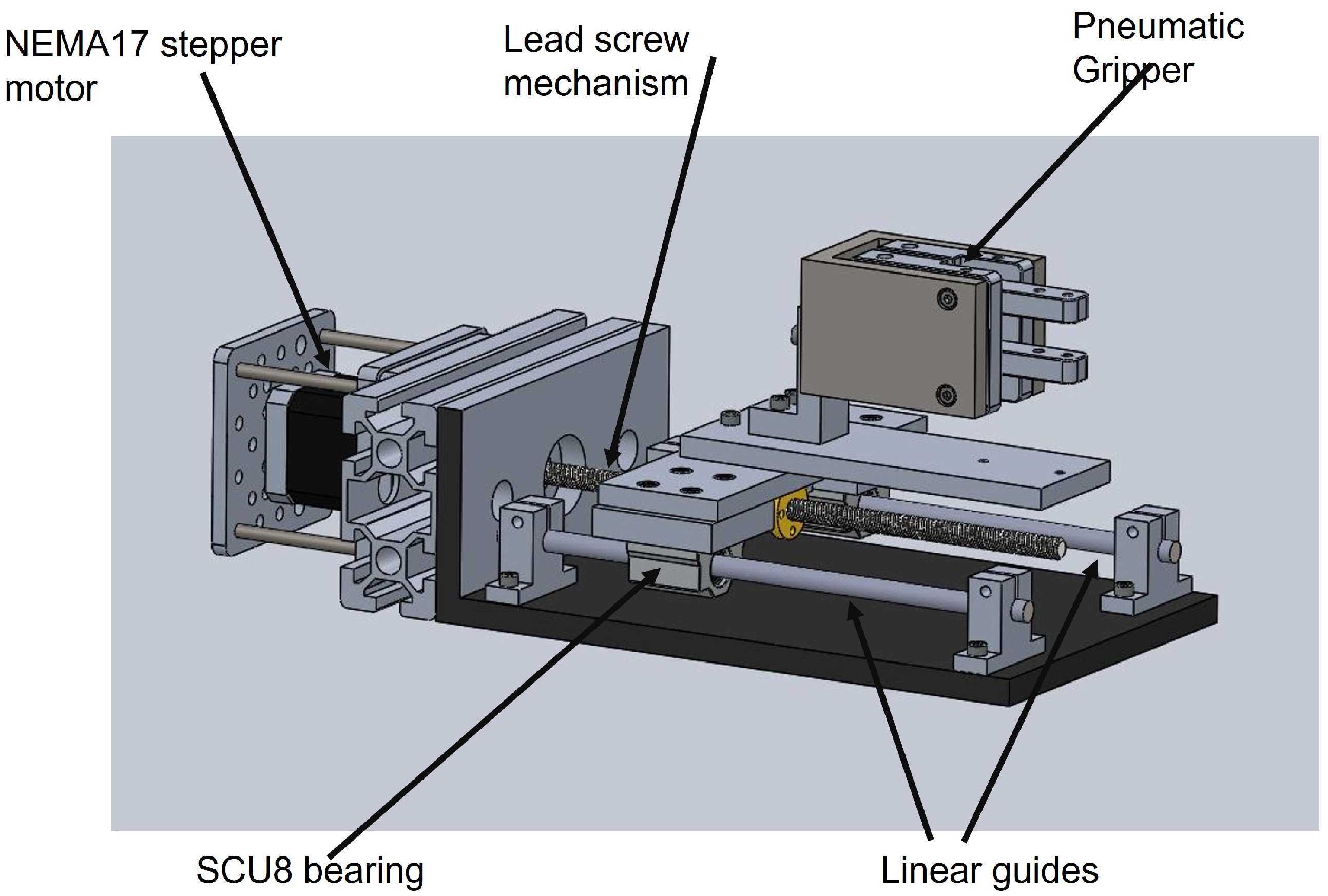
4.2. Battery Gripper

A gripper is a kind of device that enables the holding of an object to be manipulated. Comparing the “human hand” with a robotic manipulator, a “Gripper” will be on the border of the subject. Here, in this system, the battery-gripping mechanism plays a major role as it is a compulsory item for loading and unloading drone batteries. Moreover, to change the orientation of the drone battery, a secondary gripping mechanism is needed. Therefore, another compartment of the same gripper will be used to achieve that task. The gripper used here will be designed according to the size of the battery used in the drone. This will be driven by pneumatic power with a 1DOF configuration. Figure 18 shows the parts that have been used for the gripping mechanism.

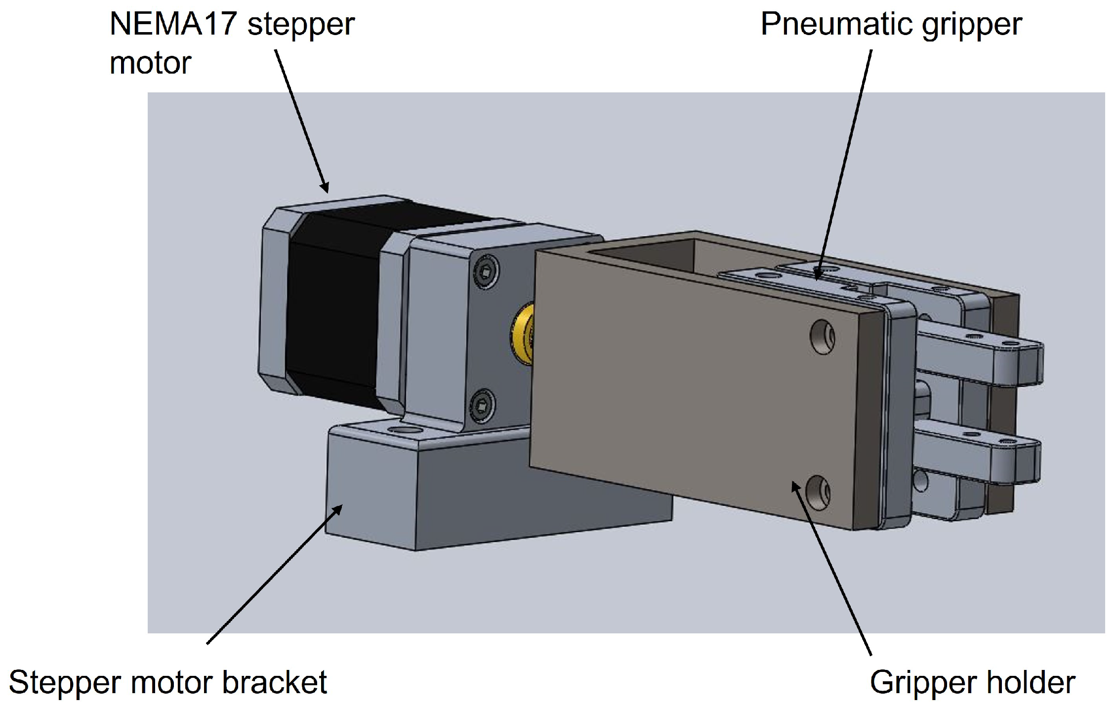
4.3. Secondary Battery Gripper

Without changing the gripper orientation, the orientaton of the battery needs to change. For this, a separate gripping mechanism is needed. This will fulfill the requirement of changing the orientation of the depleted battery when inserting it to he battery charger socket, as well the charged battery inserting again into the drone. Figure 19 shows the parts used for the secondary battery gripper.

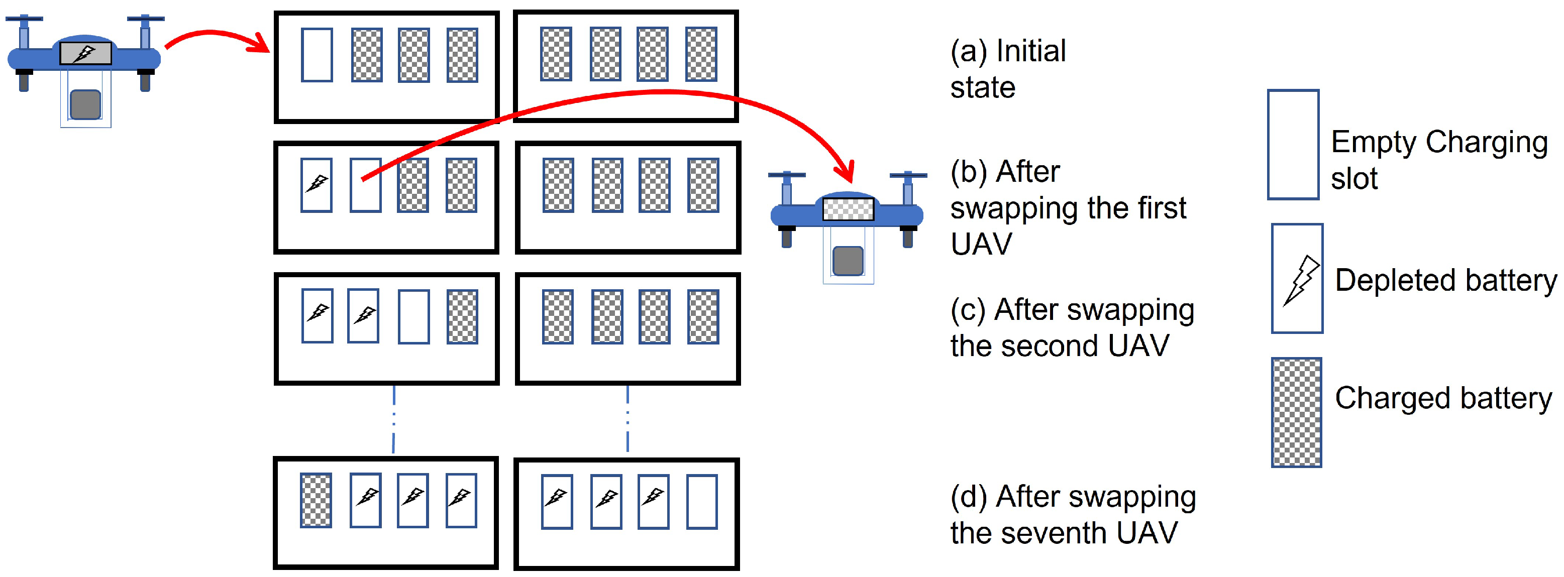
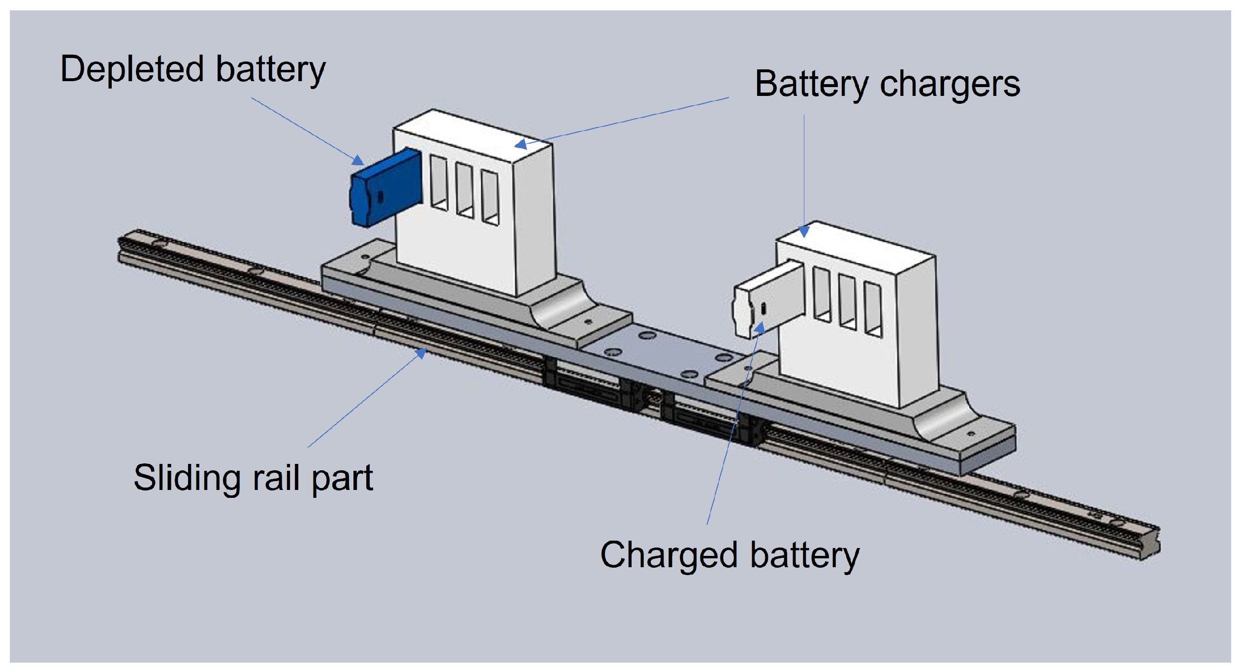
4.4. Battery Storage and Charging Unit

The battery storage and charging unit were designed according to the dimensions of the 3.8 V battery that was selected. The overall charging system has two charging units: one for the storage of the depleted batteries and the other for the charged batteries. It was observed that the drone can only fly for 13 min without the payload. Figure 20 shows the proposed idea for the operation of the battery-charging platform. In this scenario, we assumed that the UAV was in a payload condition (package delivery application) and since the payload was light, maximum flight time was be assumed to the same value. In addition, the total charging time for one battery was 90 min. Based on this approximation, it was designed with an existing four-charging-slot DJI TELLO battery charger, as in Figure 21, which shows the proposed CAD design for the battery charger platform. Figure 22 shows the overall assembly of the system.
According to Figure 20, the first charging slot of the charging unit is empty while other slots are loaded with charged batteries. After completing the first battery swapping process, that first slot will be filled with a depleted battery while the battery in the second charging slot is loaded into the UAV. Because it takes 90 min to charge a single depleted battery, completing the seventh battery swapping operation will lead to fully charging the depleted battery in the first slot.

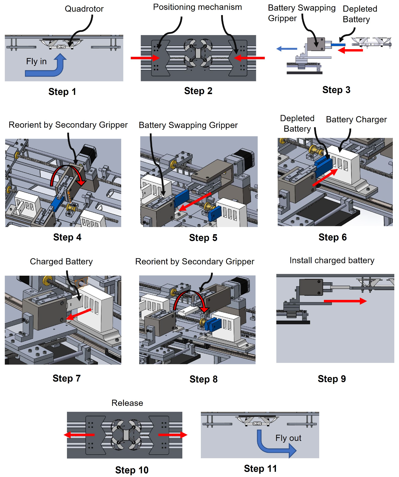
5. Motion Simulation of the Landing Platform Using CAD

Figures in this section are the 3D simulation results which were achieved by running the system in the animation mode of SOLIDWORKS 2020 software. The process starts as the drone is sticking to the ceiling. After that, the positioning mechanism is activated. The next step is to take the depleted battery out from the drone. Next, the depleted battery will be unloaded to the secondary gripper. After that, the orientation of the depleted battery in the secondary gripper will change. The next step is the unloading of the orientation-changed depleted battery to the battery-swapping gripper. Next, the depleted battery will be inserted in the battery charger, so that the charger will align with the battery-swapping gripper. After that, the depleted battery will be inserted in the battery charger. Next, the charged battery is loaded to the battery-swapping gripper. In order to do so, the charger will be aligned to the gripper. The next step is the grabbing of the charged battery. After that, the charged battery will be loaded to the secondary battery gripper. The orientation-changed battery in will be loaded to the battery-swapping gripper. Finally, this charged battery should be inserted in the drone.
The detailed steps of the simulation can be explained as follows:
  • Step 1: The quadrotor docks under the ceiling in an inverted manner by using the ceiling effect;
  • Step 2: The positioning plates clamp and center the UAV, keeping it still;
  • Step 3: The battery-swapping gripper removes the depleted battery using the method discussed in Section 3.3.3;
  • Step 4: The depleted battery orientation is changed after it is inserted into the secondary gripper as discussed in Section 3.3.4;
  • Step 5: The battery-swapping gripper takes out the reoriented depleted battery;
  • Step 6: The depleted battery is inserted to the battery charger after the charger aligned with the gripper;
  • Step 7: The swapping gripper takes a charged battery out of the charger unit. The in–out sequence of the battery was discussed in Section 3.3.3;
  • Step 8: The charged battery is reoriented by the secondary gripper;
  • Step 9: The battery-swapping gripper installs the charged battery to the quadrotor after the gripper is aligned with the battery socket of the UAV. The insertion steps were discussed in Section 3.3.3;
  • Step 10: The quadrotor is unlocked as the w-shaped positioning plates move back to initial state;
  • Step 11: The quadrotor flies out of the station.
All these steps are shown in Figure 23.

6. Results and Discussion

The research results are to be discussed in two major sections, known as the “Finite Element Analysis study (FEA)” of the platform and the locking of the drone while battery swapping happens. Later, the results will be discussed with the focus being on explaining how to construct this type of platform.

6.1. Results: Finite Element Analysis of the Landing Platform

Finite Element Analysis is the process of simulating the behavior of a part or assembly under a given condition. Simply, it shows how a certain product reacts to real-world forces: fluid-flow, heat, vibration, and other physical effects. When considering the umbrella of Mechanical Engineering, FEA will allow the user to identify the visualization of bending or twisting [52]. The software that we are using can show whether the product will break or work. Normally, the simulations in FEA will be created using a mesh of millions of smaller elements that combine to create the shape of the structure that is to be analyzed.
The proposed swapping platform contains three main parts, known as the landing platform, the battery-gripping mechanism, and the battery-charging mechanism. When paying attention to real-world scenarios, a proper material needs to be identified as the first step of designing this kind of mechanism. In this case, “Aluminum T5-6063” was used due to its high strength and low weight. To obtain further calculations, a proper drone model should be identified. The positioning mechanisms and the battery-gripping mechanism should be designed accordingly. The following Figures show the draft calculations of the maximum stress, and displacement of the design. In this scenario, the factor of safety (FOS) has been taken as 2, as was obtained from the parameters and the case study.
For the simulation, a total weight of 25 kg was applied. For the design of the landing platform, Aluminium T5-6063 was used. It is known that the yield strength of T5-6063 is 145 MPa. From that, the allowable stress can be calculated by dividing the yield strength from the FOS = 2, which is 77.5 MPa. The maximum Von Mises stress calculated from the FEA simulation was 0.7 MPa, lower than the allowable stress. From that, we are convinced that the proposed landing platform will not break.
The results that were achieved for the abovementioned FEA have been illustrated in Figure 24, Figure 25 and Figure 26.
For the landing platform, it is important to avoid bending from the center. In this case, 25 kg total force was applied to the table to perform the simulation in FEA. Here, the landing platform was fixed to the ground from the legs and the force was assumed to distribute equally along the setup. Further, a curvature-based mesh was used to create the mesh plot.
The battery-gripping operation and the secondary gripping operation were analyzed using FEA. They were checked to see whether the battery would break or not when the gripper jaws were in contact with the battery.

6.2. Results: Expected Battery Swapping Time Calculation

Data for the NEMA17 closed-loop stepper motor are in Table 5.
The following equations were used for the calculation of the motor speed.
  • Rounds per second (RPS) = ( α / 360 ) f
  • Angular velocity of the motor ( ω ) = R P S * 2 π
  • Linear velocity of the motor(v) = ( 2 π r ω ) / 60
where α denotes the step angle, f denotes the angular frequency, and r denotes the radius of the motor shaft.
The following assumptions were made for the calculation.
  • All charging ports of the charger will be filled with charged batteries;
  • The motor will be working with full power capacity;
  • Zero friction was assumed.
By substituting the values to the above equation, the value for the v can be obtained as 0.02 ms 1 . The total distance that all the actuators should travel will be 1.84 m. Dividing that value from the value v will give the expected total time for the battery swapping. By the above calculation, the expected total battery swapping time (t) = 1.5 min. All in all, the expected time was similar to the ones explained in Section 2. Future experiments with real-world items will lead us to adjust this swapping time to minimum one.

6.3. Discussion: No Tilting Feature of the UAV While Battery Swapping

Tilting of the drone happens due to numerous reasons such as motor faults, accelerometer faults, and controller errors. In the implementation of this mechanism, the drone can be tilted due to the bending moment that occurs between the positioning mechanism and the drone legs, as in Figure 27.
To stop this bending, a locking mechanism is needed to lock the positioner when in contact with the drone leg. At the same time, this locking mechanism can be used to keep the drone under the ceiling without falling. The most important thing is that the drone or the package should not be damaged throughout the operation of battery swapping. As this is to be a fully automated platform, no human interaction is needed, but an emergency shut down switch is to be installed to avoid damage to the drone.

7. Conclusions and Future Works

7.1. Conclusions

This research study proposed a novel concept: the inverted docking station. The overall goal of this research is to make an under-the-ceiling battery-swapping model which can safely swap the battery of a package-delivering drone. The mathematical model and general design guideline of the w-shaped positioning mechanism of a quadrotor were discussed and illustrated using computer-aided simulation. In addition, system-level design and detailed design of the inverted docking concept was presented with a 3D CAD model. In this paper, a small-sized quadrotor DJI TELLO was used as a case study to apply our design guideline. The constructed CAD model was virtually tested with Finite Element Analysis (FEA) and several related calculations were performed to clarify whether the proposed model is within the safety boundary. For the landing platform and the related equipment, “Aluminium 6063 T5” was used as it has a yield strength of 145 MPa. Next, the battery-grabbing mechanism and the related equipment were designed using the same material. From the values we obtained from the calculations, it has been concluded that the design is in a safe boundary. Some limitations of this proposed design are that the w-shaped positioning should work as long as the center shift error is not excessive. That is, the possible area of the legs are not overlapping with each other. If that is the case, and the center offset is high, another positioning method such as parallel plates may need to be considered. Moreover, the inverted docking requires that the UAV has top attachments that share the same height. Using the proposed concept with fixed-wing UAVs or other irregular-shape UAVs may face some difficulties.

7.2. Significance of the Research and Limitation

The advantage of the proposed method is that the package does not have to be unloaded before attempting the swapping operation. Therefore, the proposed concept can be very useful for the delivery application of UAVs. Additionally, the concept can be extended to various sizes of quadrotors by using the proposed design guideline for the w-shaped positioning plates with the landing error data. However, limitations still exist as different models mount their batteries differently. A universal battery-swapping method for all types of UAVs has not yet been identified.

7.3. Future Work and Suggestion

For future work, a prototype of the inverted docking station will be developed and tested with an actual UAV to validate the proposed concept. Actual inverted landing performance, such as landing errors with the positioning plates in the vicinity will also be investigated. As a suggestion for future research, an expansion of the inverted docking system to other multirotor models should be considered. Furthermore, the load limitation and stability of the UAV during the swap should be studied. Finally, a universal battery swapping socket can be implemented in order to swap to other kinds of batteries in UAVs.

Author Contributions

Conceptualization, M.P. and P.R.; Data curation, S.C.D.S.; Formal analysis, S.C.D.S.; Funding acquisition, M.P. and P.R.; Investigation, S.C.D.S.; Methodology, S.C.D.S.; Project administration, M.P.; Resources, S.R. and P.R.; Software, S.C.D.S.; Supervision, M.P., S.R. and P.R.; Visualization, M.P., S.R. and P.R.; Writing—original draft, S.C.D.S. and M.P.; Writing—review & editing, S.C.D.S., M.P., S.R. and P.R. All authors have read and agreed to the published version of the manuscript.

Funding

This study was supported by Thammasat University Research Fund, Contract No. TUFT 054/2563 and has been partly supported by the KAKENHI Fund for the Promotion of Joint International Research (fostering joint international research (B) No. JP20KK0086).

Institutional Review Board Statement

Not applicable.

Informed Consent Statement

Not applicable.

Data Availability Statement

Not applicable.

Conflicts of Interest

The authors declare no conflict of interest.

References

  1. Radiansyah, S.; Kusrini, M.D.; Prasetyo, L.B. Quadcopter applications for wildlife monitoring. IOP Conf. Ser. Earth Environ. Sci. 2017, 54, 012066. [Google Scholar] [CrossRef] [Green Version]
  2. Townsend, A.; Jiya, I.N.; Martinson, C.; Bessarabov, D.; Gouws, R. A comprehensive review of energy sources for unmanned aerial vehicles, their shortfalls and opportunities for improvements. Heliyon 2020, 6, e05285. [Google Scholar] [CrossRef] [PubMed]
  3. Hassija, V.; Saxena, V.; Chamola, V. Scheduling drone charging for multi-drone network based on consensus time-stamp and game theory. Comput. Commun. 2020, 149, 51–61. [Google Scholar] [CrossRef]
  4. Mostafa, T.M.; Muharam, A.; Hattori, R. Wireless battery charging system for drones via capacitive power transfer. In Proceedings of the 2017 IEEE PELS Workshop on Emerging Technologies: Wireless Power Transfer (WoW), Chongqing, China, 20–22 May 2017; pp. 1–6. [Google Scholar] [CrossRef]
  5. Junaid, A.B.; Lee, Y.; Kim, Y. Design and implementation of autonomous wireless charging station for rotary-wing UAVs. Aerosp. Sci. Technol. 2016, 54, 253–266. [Google Scholar] [CrossRef]
  6. Junaid, A.B.; Konoiko, A.; Zweiri, Y.; Sahinkaya, M.N.; Seneviratne, L. Autonomous Wireless Self-Charging for Multi-Rotor Unmanned Aerial Vehicles. Energies 2017, 10, 803. [Google Scholar] [CrossRef]
  7. Yang, C.; He, Y.; Qu, H.; Wu, J.; Hou, Z.; Lin, Z.; Cai, C. Analysis, design and implement of asymmetric coupled wireless power transfer systems for unmanned aerial vehicles. AIP Adv. 2019, 9, 025206. [Google Scholar] [CrossRef] [Green Version]
  8. Campi, T.; Dionisi, F.; Cruciani, S.; De Santis, V.; Feliziani, M.; Maradei, F. Magnetic field levels in drones equipped with Wireless Power Transfer technology. In Proceedings of the 2016 Asia-Pacific International Symposium on Electromagnetic Compatibility (APEMC), Shenzhen, China, 17–21 May 2016; Volume 1, pp. 544–547. [Google Scholar] [CrossRef]
  9. Mourgelas, C.; Kokkinos, S.; Milidonis, A.; Voyiatzis, I. Autonomous drone charging stations: A survey. In Proceedings of the PCI 2020: 24th Pan-Hellenic Conference on Informatic, Athens Greece, 20–22 November 2020; pp. 233–236. [Google Scholar] [CrossRef]
  10. Mulgaonkar, Y.; Kumar, V. Autonomous charging to enable long-endurance missions for small aerial robots. In Micro- and Nanotechnology Sensors, Systems, and Applications VI; George, T., Islam, M.S., Dutta, A.K., Eds.; International Society for Optics and Photonics, SPIE: Bellingham, WA, USA, 2014; Volume 9083, pp. 404–418. [Google Scholar] [CrossRef]
  11. Cocchioni, F.; Pierfelice, V.; Benini, A.; Mancini, A.; Frontoni, E.; Zingaretti, P.; Ippoliti, G.; Longhi, S. Unmanned Ground and Aerial Vehicles in extended range indoor and outdoor missions. In Proceedings of the 2014 International Conference on Unmanned Aircraft Systems (ICUAS), Orlando, FL, USA, 27–30 May 2014; pp. 374–382. [Google Scholar] [CrossRef]
  12. Song, B.D.; Kim, J.; Kim, J.; Park, H.; Morrison, J.R.; Shim, D.H. Persistent UAV service: An improved scheduling formulation and prototypes of system components. In Proceedings of the 2013 International Conference on Unmanned Aircraft Systems (ICUAS), Atlanta, GA, USA, 28–31 May 2013; pp. 915–925. [Google Scholar] [CrossRef]
  13. Leahy, K.; Zhou, D.; Vasile, C.I.; Oikonomopoulos, K.; Schwager, M.; Belta, C. Persistent surveillance for unmanned aerial vehicles subject to charging and temporal logic constraints. Auton. Robot. 2016, 40, 1363–1378. [Google Scholar] [CrossRef]
  14. Kemper, F.; Suzuki, K.; Morrison, J. UAV Consumable Replenishment: Design Concepts for Automated Service Stations. J. Intell. Robot. Syst. 2011, 61, 369–397. [Google Scholar] [CrossRef]
  15. Ahmad Shah, S.; Hamid, S.; Liyana, N.; Norhashim, N.; Sahwee, Z.; Rafael, A.; Zolkifli, I. Experimental evaluation of solar charge controller installed in a solar-powered Unmanned Aerial Vehicle (UAV). Def. S T Tech. Bull. 2021, 14, 198–210. [Google Scholar]
  16. Swieringa, K.A.; Hanson, C.B.; Richardson, J.R.; White, J.D.; Hasan, Z.; Qian, E.; Girard, A. Autonomous battery swapping system for small-scale helicopters. In Proceedings of the 2010 IEEE International Conference on Robotics and Automation, Anchorage, AK, USA, 3–7 May 2010; pp. 3335–3340. [Google Scholar] [CrossRef]
  17. Grlj, C.G.; Krznar, N.; Pranjić, M. A Decade of UAV Docking Stations: A Brief Overview of Mobile and Fixed Landing Platforms. Drones 2022, 6, 17. [Google Scholar] [CrossRef]
  18. Cokyasar, T.; Dong, W.; Jin, M.; Verbas, İ.Ö. Designing a drone delivery network with automated battery swapping machines. Comput. Oper. Res. 2021, 129, 105177. [Google Scholar] [CrossRef]
  19. Simic, M.; Bil, C.; Vojisavljevic, V. Investigation in Wireless Power Transmission for UAV Charging. Procedia Comput. Sci. 2015, 60, 1846–1855. [Google Scholar] [CrossRef] [Green Version]
  20. Belmonte, N.; Staulo, S.; Fiorot, S.; Luetto, C.; Rizzi, P.; Baricco, M. Fuel cell powered octocopter for inspection of mobile cranes: Design, cost analysis and environmental impacts. Appl. Energy 2018, 215, 556–565. [Google Scholar] [CrossRef]
  21. Ucgun, H.; Yuzgec, U.; Bayilmis, C. A review on applications of rotary-wing unmanned aerial vehicle charging stations. Int. J. Adv. Robot. Syst. 2021, 18, 17298814211015863. [Google Scholar] [CrossRef]
  22. Galkin, B.; Kibilda, J.; Dasilva, L. UAVs as Mobile Infrastructure: Addressing Battery Lifetime. IEEE Commun. Mag. 2019, 57, 132–137. [Google Scholar] [CrossRef] [Green Version]
  23. Choi, C.; Jang, H.; Lim, S.; Lim, H.; Cho, S.; Gaponov, I. Automatic wireless drone charging station creating essential environment for continuous drone operation. In Proceedings of the 2016 International Conference on Control, Automation and Information Sciences (ICCAIS), Ansan, Korea, 27–29 October 2016; pp. 132–136. [Google Scholar] [CrossRef]
  24. Park, C.W. A Study on Drone Charging System Using Wireless Power Transmission. Master’s Thesis, Busan University of Foreign Studies Graduate School, Busan, Korea, 2016. [Google Scholar]
  25. Xuan-Mung, N.; Hong, S.K.; Nguyen, N.P.; Ha, L.N.N.T.; Le, T.L. Autonomous Quadcopter Precision Landing Onto a Heaving Platform: New Method and Experiment. IEEE Access 2020, 8, 167192–167202. [Google Scholar] [CrossRef]
  26. Cabecinhas, D.; Naldi, R.; Silvestre, C.; Cunha, R.; Marconi, L. Robust Landing and Sliding Maneuver Hybrid Controller for a Quadrotor Vehicle. IEEE Trans. Control. Syst. Technol. 2016, 24, 400–412. [Google Scholar] [CrossRef]
  27. Gonçalves, V.M.; McLaughlin, R.; Pereira, G.A.S. Precise Landing of Autonomous Aerial Vehicles Using Vector Fields. IEEE Robot. Autom. Lett. 2020, 5, 4337–4344. [Google Scholar] [CrossRef]
  28. Saripalli, S.; Sukhatme, G. An Experimental Study of the Autonomous Helicopter Landing Problem. In Experimental Robotics VIII; Springer: Berlin/Heidelberg, Germany, 2004. [Google Scholar] [CrossRef] [Green Version]
  29. Lee, D.; Ryan, T.; Kim, H.J. Autonomous landing of a VTOL UAV on a moving platform using image-based visual servoing. In Proceedings of the 2012 IEEE International Conference on Robotics and Automation, Saint Paul, MN, USA, 14–18 May 2012; pp. 971–976. [Google Scholar] [CrossRef]
  30. Cui, E.; Zhang, X. Ground Effect Aerodynamics. In Encyclopedia of Aerospace Engineering; John Wiley & Sons, Ltd.: Hoboken, NJ, USA, 2010. [Google Scholar] [CrossRef]
  31. Enrique, J.C.M.; David, E.C.; David, S.J.; Ivan, M.; Fernando, C. Device and Method for Use with Unmanned Aerial Vehicles. U.S. Patent 9,481,458, 1 November 2016. [Google Scholar]
  32. Godzdanker, R.; Valavanis, K.P.; Rutherford, M.J. Intelligent Self-Leveling Docking System. W.O. Patent 2012,0648,91A3, 12 July 2012. [Google Scholar]
  33. Fox, Y.; Meir, K.; Krauss, R. Positioning and Locking System and Method for Unmanned Vehicles. U.S. Patent 2019,0202,578A1, 4 July 2019. [Google Scholar]
  34. Lushizou, D.; Ren, Y.; Jie, T.; Sun, Q. A Kind of Unmanned Plane Relay. U.S. Patent 2064,855,85U, 12 September 2017. [Google Scholar]
  35. Krauss, R.; Kliner, M. Unmanned Aerial Vehicle Charging Station with Centering Mechanism. W.O. Patent 2017,130,181A1, 3 August 2017. [Google Scholar]
  36. Çakici, F.; Leblebicioğlu, M.K. Control System Design of a Vertical Take-off and Landing Fixed-Wing UAV. IFAC-PapersOnLine 2016, 49, 267–272. [Google Scholar] [CrossRef]
  37. Antonini, R.; Fici, G.P.; Gaspardone, M. Landing Platform for Unmanned Aerial Vehicles. W.O. Patent 2015,117,216A1, 13 August 2015. [Google Scholar]
  38. Kim, J.; Song, C.-U. Three-Phase Wireless Power Transfer System And Three-Phase Wireless Chargeable Unmanned Aerial Vehicle System Based On The Same. U.S. Patent 2018,0056,794A1, 25 September 2018. [Google Scholar]
  39. A.R.Gabdullin, M.M.Galimov, A. Landing Place for Drone. R.U. Patent 27,1088,7c1, 14 January 2020.
  40. Alhadi, S.; Rianmora, S.; Phlernjai, M. Conceptual Design and Analysis of Small Power Station for Supporting Unmanned Aerial Vehicle (UAV) Deployment. Eng. J. 2021, 25, 51–71. [Google Scholar] [CrossRef]
  41. Barbasov, K.B.V. System of Landing of Unmanned Aerial Vehicle and Landing Vehicle of Verticle Take-off and Landing. RU Patent RU26,669,75c1, 13 September 2018. [Google Scholar]
  42. Miyazaki, R.; Jiang, R.; Paul, H.; Ono, K.; Shimonomura, K. Airborne Docking for Multi-Rotor Aerial Manipulations. In Proceedings of the 2018 IEEE/RSJ International Conference on Intelligent Robots and Systems (IROS), Madrid, Spain, 1–5 October 2018; pp. 4708–4714. [Google Scholar] [CrossRef]
  43. Liu, Z.N.; Liu, X.Q.; Yang, L.J.; Leo, D.; Zhao, H.W. An Autonomous Dock and Battery Swapping System for Multirotor UAV. 2018; preprint. [Google Scholar] [CrossRef]
  44. Lee, D.; Zhou, J.; Lin, W.T. Autonomous battery swapping system for quadcopter. In Proceedings of the 2015 International Conference on Unmanned Aircraft Systems (ICUAS), Denver, CO, USA, 9–12 June 2015; pp. 118–124. [Google Scholar] [CrossRef]
  45. Toksoz, T.; Redding, J.; Michini, M.; Michini, B.; How, J.; Vavrina, M.; Vian, J. Automated Battery Swap and Recharge to Enable Persistent UAV Missions. In Proceedings of the Infotech@Aerospace 2011, St. Louis, MO, USA, 29–31 March 2011. [Google Scholar] [CrossRef] [Green Version]
  46. Suzuki, K.; Filho, P.; Morrison, J. Automatic Battery Replacement System for UAVs: Analysis and Design. J. Intell. Robot. Syst. 2012, 65, 563–586. [Google Scholar] [CrossRef]
  47. Ure, N.K.; Chowdhary, G.; Toksoz, T.; How, J.P.; Vavrina, M.A.; Vian, J. An Automated Battery Management System to Enable Persistent Missions With Multiple Aerial Vehicles. IEEE/ASME Trans. Mechatron. 2015, 20, 275–286. [Google Scholar] [CrossRef]
  48. Matus-Vargas, A.; Gómez, G.; Martinez-Carranza, J. Ground effect on rotorcraft unmanned aerial vehicles: A review. Intell. Serv. Robot. 2021, 14, 1–20. [Google Scholar] [CrossRef]
  49. Wang, X.; Du, S.; Liu, Y. Research on Ceiling Effect of Quadrotor. In Proceedings of the 2017 IEEE 7th Annual International Conference on CYBER Technology in Automation, Control, and Intelligent Systems (CYBER), Honolulu, HI, USA, 31 July–4 August 2017; pp. 846–851. [Google Scholar] [CrossRef]
  50. Hsiao, Y.; Chirarattananon, P. Ceiling Effects for Hybrid Aerial-Surface Locomotion of Small Rotorcraft. IEEE/ASME Trans. Mechatronics 2019, 24, 2316–2327. [Google Scholar] [CrossRef] [Green Version]
  51. Cabas, R.; Balaguer, C. Design and development of a light weight embodied robotic hand activated with only one actuator. In Proceedings of the 2005 IEEE/RSJ International Conference on Intelligent Robots and Systems, Edmonton, AB, Canada, 2–6 August 2005; pp. 2369–2374. [Google Scholar] [CrossRef]
  52. Ali Abotiheen, M.H. Finite Element Analysis is A Powerful Approach To Predictive Manufacturing Parameters. J. Univ. Babylon 2017, 26, 229–238. [Google Scholar]
Figure 1. Inverted docking under the ceiling with Package; (Left) The UAV hovers under a ceiling surface. (Right) The UAV sticks to the ceiling using the ceiling effect.
Drones 06 00056 g001
Figure 2. Overall idea of the proposed model.
Drones 06 00056 g002
Figure 3. Force and air flow performance: (a) when drone flies near to the ground (b) when drone flies near to the ceiling.
Drones 06 00056 g003
Figure 4. Overall idea of the proposed study: (a) quadrotor UAV sticking to the ceiling; (b) positioning and locking of quadrotor; (c) swapping of the battery; (d) flying the drone.
Drones 06 00056 g004
Figure 5. DJI RYZE TELLO drone to be used for the experiment.
Drones 06 00056 g005
Figure 6. Inverted landing experiment: offset and rotation from the precise position.
Drones 06 00056 g006
Figure 7. Free body diagram of the drone legs and positioning plates when the drone leg contacts the positioning plate.
Drones 06 00056 g007
Figure 8. Size of the DJI RYZE TELLO drone.
Drones 06 00056 g008
Figure 9. Simulation of possible landing area at each leg with extreme center shift.
Drones 06 00056 g009
Figure 10. A quadrotor clamped by the positioning plates.
Drones 06 00056 g010
Figure 11. Dimensions of the designed positioning plate.
Drones 06 00056 g011
Figure 12. Conceptual figure of the battery-swapping operation: (a) Unlocking (b) Gripping (c) Attaching (d) Locking.
Drones 06 00056 g012
Figure 13. The conceptual idea of hitting the battery with the gripper jaw.
Drones 06 00056 g013
Figure 14. The conceptual idea of the battery charger orientation change.
Drones 06 00056 g014
Figure 15. Conceptual figure of the battery-swapping gripper and secondary battery gripper: (a) before secondary gripper operating; (b) after secondary gripper operating.
Drones 06 00056 g015
Figure 16. Proposed system-level design of the total system.
Drones 06 00056 g016
Figure 17. Table-shaped station with positioning mechanism (a) Whole model (b) View from Top (c) View from bottom.
Drones 06 00056 g017
Figure 18. Proposed system-level design of the battery-swapping gripper.
Drones 06 00056 g018
Figure 19. Proposed system-level design of the secondary battery gripper.
Drones 06 00056 g019
Figure 20. Proposed idea for the operation of battery-charging platform.
Drones 06 00056 g020
Figure 21. Proposed system-level design of the battery-charging platform.
Drones 06 00056 g021
Figure 22. Overall assembly designed.
Drones 06 00056 g022
Figure 23. CAD Simulation results.
Drones 06 00056 g023
Figure 24. Simulation Results for the landing platform: (a) Von Mises stress; (b) displacement; (c) strain.
Drones 06 00056 g024
Figure 25. Simulation results for the battery-swapping gripper: (a) Von Mises stress; (b) displacement; (c) strain.
Drones 06 00056 g025
Figure 26. Simulation results for the secondary battery gripper: (a) Von Mises stress; (b) displacement; (c) strain.
Drones 06 00056 g026
Figure 27. The conceptual design of the idea of tilting of the drone due to positioning: (a) activation of positioning; (b) after positioning; (c) tilting of the drone.
Drones 06 00056 g027
Table 1. Pros and cons of “Active” positioning techniques.
Positioning MechanismActivation TypeProsCons
Drones 06 00056 i001Parallel pushing [31,32].Supports a wide range of UAV sizes.
Can position the drone at any desired point.
Limited to even number of legs.
Separated 2-DOF pusher control.
Drones 06 00056 i002V- and W-shaped pushing [33,34].Simple control with 1-DOF.Limited to symmetrical leg structure.
Cannot easily change clamping positions.
Drones 06 00056 i003Aligned by rotating [35].Simple control with 1-DOF.The rotation center may obstruct the landing and limit UAV size.
Can be looser than other types.
Drones 06 00056 i004Iris Diaphragm [36].Support wide range of UAV sizes.Complex and harder to maintain.
No orientation lock.
Table 2. Pros and cons of “Passive” positioning techniques.
Positioning MechanismType of PositioningProsCons
Drones 06 00056 i005Funnels used for each leg [37].No moving devices or mechanisms.
Clamping can be done easily.
Limited to lower number of legs.
Drones 06 00056 i006One funnel used for all legs [38,39].Clamping can be done easily.However, the clamping is poor compared to previous method.
Drones 06 00056 i007One funnel used for the whole body of the UAV [38,39].Simple landing compared to previous two methods.Clamping is poor compared to previous two methods.
   Drones 06 00056 i008Overhead funnel positioning [41].Size of the UAV does not matter.Requires a more-advanced technology than others.
Table 3. Pros and cons of both positioning techniques.
Landing Platforms Using “Active” PositionersLanding Platforms Using “Passive” Positioners
The drone will be fixed to a particular position.Deviation can happen due to wind condition.
Landing precision is not compulsory.Landing precision is compulsory.
Proper controlling strategies should be used.Only gravitational force will be used to land and position.
Table 4. Inverted docking experiments: shift radius and rotational error legs.
TrialRadius of Shift r [mm]Angle of Rotational Error θ [degrees]
Initial0.00.0
11.017.4
23.012.1
31.4−59.1
470.7−12.1
565.630.0
660.828.2
763.230.2
820.622.6
920.6−1.0
1022.6−2.0
Average30.36.6
Standard Deviation22.827.4
Table 5. NEMA17 closed-loop stepper motor characteristics.
MotorNEMA17 Closed Loop Stepper
Motor Torque (T)200 steps/Rev
Step Angle ( α )1.8 degrees
Operation Frequency (f)1500 Hz
Publisher’s Note: MDPI stays neutral with regard to jurisdictional claims in published maps and institutional affiliations.

