1. Introduction
Over the past decade commercial drones, and quadcopters in particular, have become increasingly popular and affordable. In addition to their use in professional or casual photography, they have grown into a transformative force in diverse sectors, including inspection [
1,
2], mapping [
3,
4], exploration [
5], human–machine interaction [
6], search-and-rescue missions [
7,
8], and more. More recently, their combination with virtual and augmented reality (VR and AR, respectively) has yielded new experiences such as first-person-view (FPV) fights (
www.dji.com/gr/dji-fpv, accessed on 20 December 2021), AR training (
vrscout.com/news/dronoss-training-drone-pilots-with-ar/, accessed on 20 December 2021), and mixed reality games (
www.dji.com/newsroom/news/edgybees-launches-the-first-augmented-reality-game-for-dji-drone-users, accessed on 20 December 2021).
Learning to pilot a quadcopter effectively can be a challenging task: Conventional remote controllers are largely unintuitive, as they use two joysticks to control flight, with one corresponding to horizontal motions (pitch and roll) and the other to vertical (throttle) and rotational (yaw) motions. Additional wheels and buttons control the drone’s camera. While basic motions in relaxed circumstances are achievable with short training sessions, complex motions can be more difficult. Moreover, in challenging or stressful circumstances (e.g., in disaster response or under tight time constraints), the lack of intuitive controls add additional cognitive load on the pilot, affecting his/her safety and efficiency. In addition, the remote controller in itself, requiring the continuous use of both hands, can be restrictive. Although alternative remote controllers, such as the DJI motion controller, provide a less cumbersome solution, they cannot support the full range of motions executable by a traditional remote.
Another challenge stems from the difference in position and orientation between the drone and its pilot, which can make it difficult to match the drone’s camera feed with the pilot’s surroundings. In particular, especially when the drone is at some distance or out of direct line of sight, it can be challenging both to judge its position and orientation and have a direct understanding of where its camera is pointing at. Moreover, as the video feed is normally displayed on a screen attached to the remote, it requires users to constantly change their focus from the drone (in the air) to the screen (usually held at chest level, hence towards the ground), glancing from one to the other. This can be both tiring (mentally as well as visually) and adds to the cognitive load, as the user alternates between two different points of view. Although VR FPV mode eliminates the change of perspective, it leaves users unaware of their own surroundings, which can be prohibitive in many cases.
In this paper, we propose an AR solution that leverages gesture recognition, computer vision AI, and motion tracking techniques to provide a natural user interface for intuitive drone control and contextualized information visualization. Based on the Microsoft HoloLens 2 headset (
https://www.microsoft.com/en-us/hololens/hardware, accessed on 20 December 2021), the presented system allows users to pilot a drone using single-hand gestures, improves tracking the position of the drone in an AR environment, and provides video feed visualization in either the contextualized or FPV modes. It allows for a comfortable flight, as both hands are free and can be used for other tasks when not directing the drone. AR tracking improves drone visibility in longer distances or in low light conditions. The visualization of the drone’s video feed in the AR display means that users can view both the video and their surroundings without glancing towards different directions. In conjunction with tracking, a contextualized video view projects the video in the approximate location and/or direction of its contents, considering the drone’s location and orientation, resulting in a mixed reality view combining the virtual video feed with the real world. The main contributions of this work are as follows:
Gesture control for drones, supporting all drone and camera motions, including complex motions;
Drone tracking in AR, based on cumulative Inertial Measurement Unit (IMU) readings and an initial relative pose calibration, while exploring visual-based drift correction;
Visualization of the drone’s camera feed in AR in context with the real world, considering the relative pose between drone and user, with the additional option to explore and integrate depth estimation for more accurate placement.
A unified solution encompassing all of the above, consisting of a HoloLens 2 user interface app, an Android UAV interface app, and a Kafka message broker.
The rest of the paper is organized as follows:
Section 2 discusses earlier work related to the presented solution, in particular regarding drone gesture control, drone tracking, and the visualization of information in AR;
Section 3 presents the system’s architecture, including hardware, software, communication, and data flow;
Section 4 describes the primary technical tasks that were needed to realize the solution;
Section 5 discusses the testing of the system, including subjective and objective measurements and feedback; and finally,
Section 6 summarizes this work and outlines possible future developments.
3. Architecture
3.1. Overview
As stated in
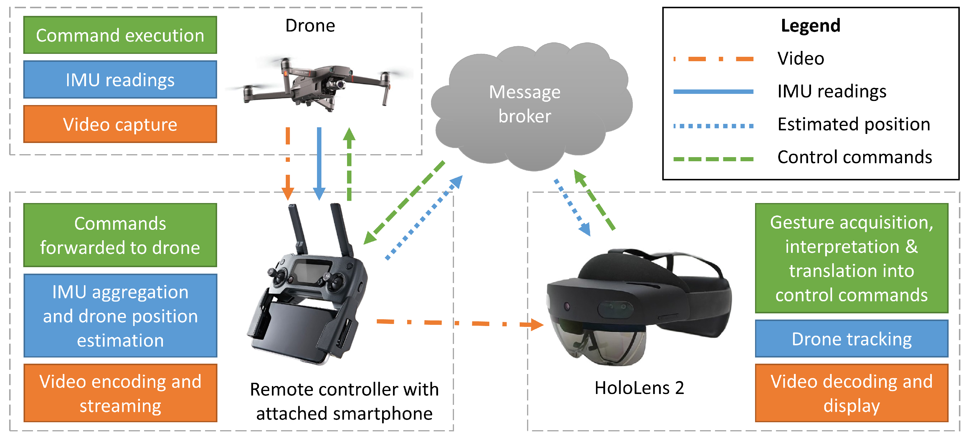
Section 1, the main focus of this work is to provide drone pilots with intuitive gesture control, drone tracking in AR, and a video feed displayed in context with the real environment. This section presents the system architecture developed (depicted in
Figure 1) to support these functionalities.
The two end-points of the system are the pilot and the drone. The pilot interacts with the system via an autonomous mixed reality headset that provides hand-tracking capabilities along with visualization in AR. A HoloLens application was developed to support gesture acquisition, give feedback to the pilot, display the received video feed and the drone’s tracked position in AR, and handle connectivity and common settings. The drone connects with the system via a direct wireless link with its remote controller, which is connected to a smartphone running a custom Android app to support the needed functionalities. These include transmitting telemetry data from the drone to the AR device and control commands from the AR device to the drone. The communication between the AR device and the drone is routed through a message broker, while the video data are streamed via a direct socket connection between the smartphone and the AR device.
There are three primary data flows pertinent to the desired functionalities:
Hand gestures are captured, interpreted, translated to drone commands, and forwarded to the drone.
Telemetry data are used to estimate the drone’s current position, which is then sent to the AR device.
Live video is captured by the drone’s camera, transmitted to the remote controller, and then streamed to the AR device directly.
The remainder of this section further describes the individual system components and their functionalities, while the next section (
Section 4) provides technical details regarding the main components of the solution.
3.2. Hardware
The main hardware devices used in the proposed solution are the drone, and the AR device used as a user-interface, both of which are briefly described below. Additional hardware, such as the smartphone connected to the drone’s remote and the computer server hosting the message broker, are generic and need no further elaboration.
Developing and testing the architecture was performed using DJI’s Mavic 2 Enterprise Dual and Mavic Mini drones. The DJI Mobile SDK platform offers high-level control of the aircraft and the camera–gimbal system, low latency video feed retrieval from the camera, and state information about the aircraft and the controller through various sensors, all of which are essential for development. For outdoor testing, we primarily used the larger Mavic 2 Enterprise Dual drone with its onboard obstacle avoidance system, which was important for safety reasons when implementing gesture control. For indoor testing, the smaller and lighter Mavic Mini was used.
Microsoft’s HoloLens 2 was used as an augmented reality platform. HoloLens is a head-mounted system that can display virtual objects in the real world, with the use of two see-through holographic displays. It has a plethora of onboard sensors to understand its surrounding environment (spatial mapping) including four RGB cameras, which combined with a Time-of-Flight Depth sensor, are used to track the user’s hands. In addition, two infrared cameras are tracking the user’s eyes, optimizing object rendering, and a microphone array can be used to issue voice commands. We capture hand tracking data through the HoloLens interface and translate them into UAV commands to control the drone and the camera. We also use the head tracking information the HoloLens provides to rotate the drone in accordance to head movement. HoloLens was selected because it provides three features necessary for the presented application: AR visualization, hand tracking, and autonomous operation (i.e., not tethered to a computer).
3.3. Communication
Information exchange between the different modules of the presented architecture is achieved via the Kafka (
https://kafka.apache.org/, accessed on 20 December 2021) message broker. We use Confluent’s implementation (
https://www.confluent.io/, accessed on 20 December 2021), which includes a built-in REST proxy and a corresponding API, which are necessary since there are no Kafka clients compatible with UWP (Universal Windows Platform) and the HoloLens. The broker’s contents are organized into topics, and each topic corresponds to different functionality of the system (e.g., control commands, positioning info, etc.). The messages abide by the JSON protocol, which is natively supported by Kafka, and their structure is strictly defined. This not only ensures compatibility between modules but also provides significant modularity since new message types can be added, removed, or modified in future versions since they comply with the same JSON structure. Finally, our modules use HTTP operations (POST, GET) to produce and consume the stated messages.
3.4. Augmented Reality Application
Drone control commands: This module is responsible for capturing the gesture/voice interactions of the user, translating them to specific control commands (i.e., pitch, roll, yaw, and throttle values), and sending them to the the Android app via the Kafka broker.
Drone tracking: The drone tracking module is responsible for monitoring the spatial relation between the real world elements (the drone and the app user) and its virtual representatives. Drone tracking is the backbone for many feedback cues (visual, textual, contextualized videos) that provide the user with enhanced spatial perception. Tracking is possible following an initial calibration process and an IMU-based approach.
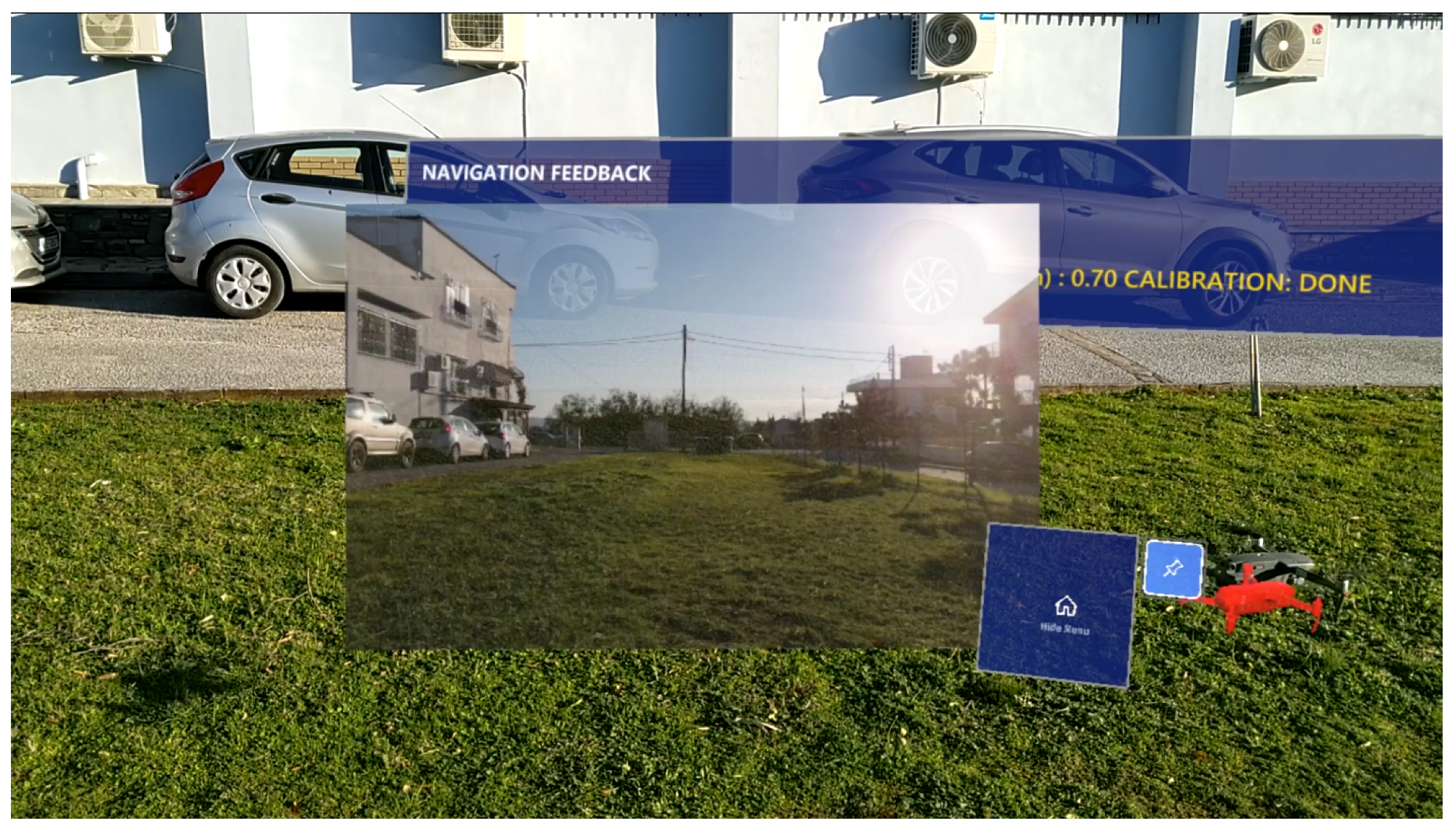
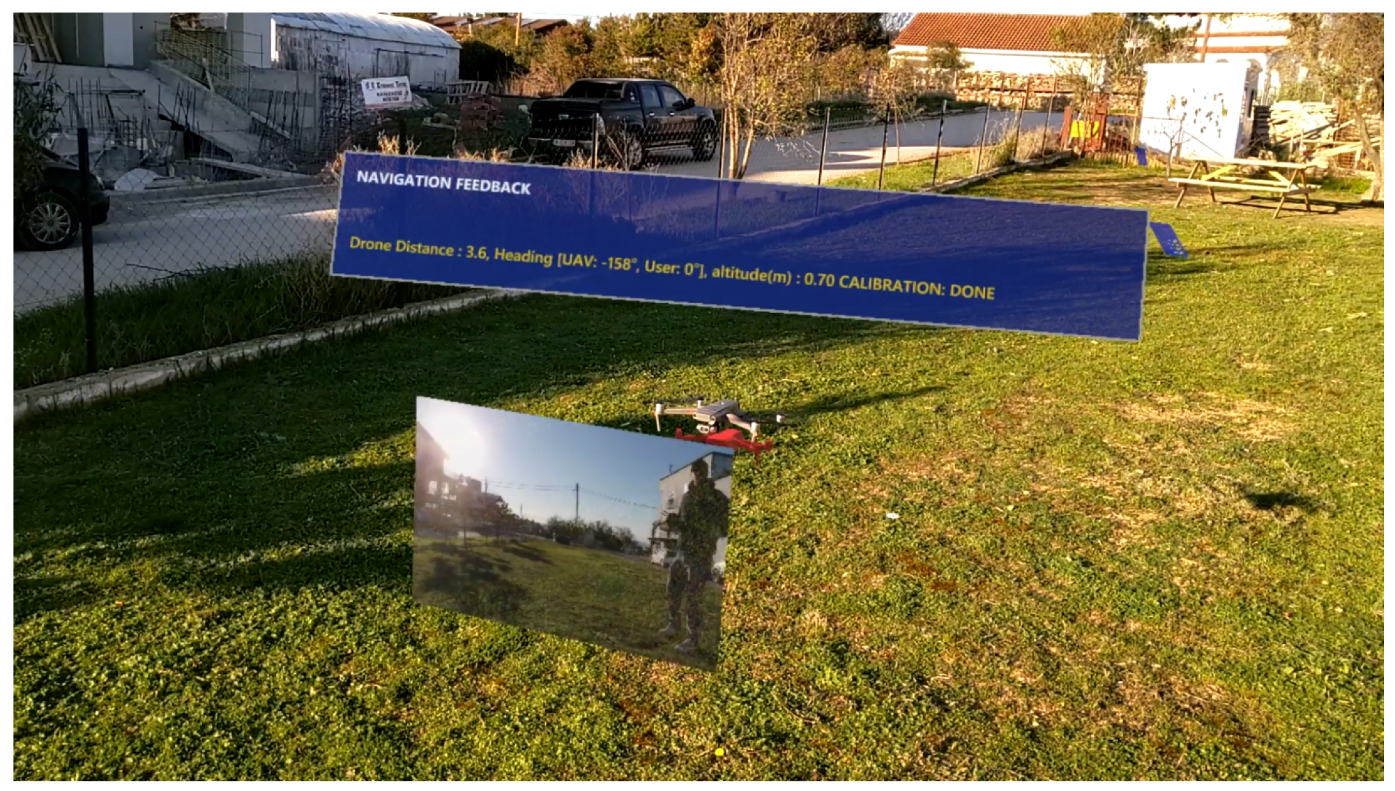
Video feedback: The live video feed from the drone’s camera is projected on a canvas inside the augmented environment. The user can simultaneously be aware of his/her surroundings in the real environment while also viewing the drone’s video feed in his/her field of view (FoV). With minimal head movement and loss of focus, the user can perceive the surrounding environment from two different viewpoints. This video projection is modifiable and can either be placed in the center of the user’s FoV as shown in
Figure 2 (FPV mode) or on a smaller panel projected from the drone’s virtual counterpart (
Figure 3). The center placement is useful in tasks where higher detail of the drone’s camera feed is required. This contextualized video feed mode is called “egocentric” view with the drone at the center and allows for easier perception of what the drone “sees” during the flight and of the spatial correspondence between the drone’s and the user’s point of view. In contrast, the FPV mode is useful in tasks where higher detail of the drone’s camera feed is required. In addition, when using a drone equipped with an infrared camera, the user can choose between three different modalities, visible (RGB), infrared (IR), or fused (MSX).
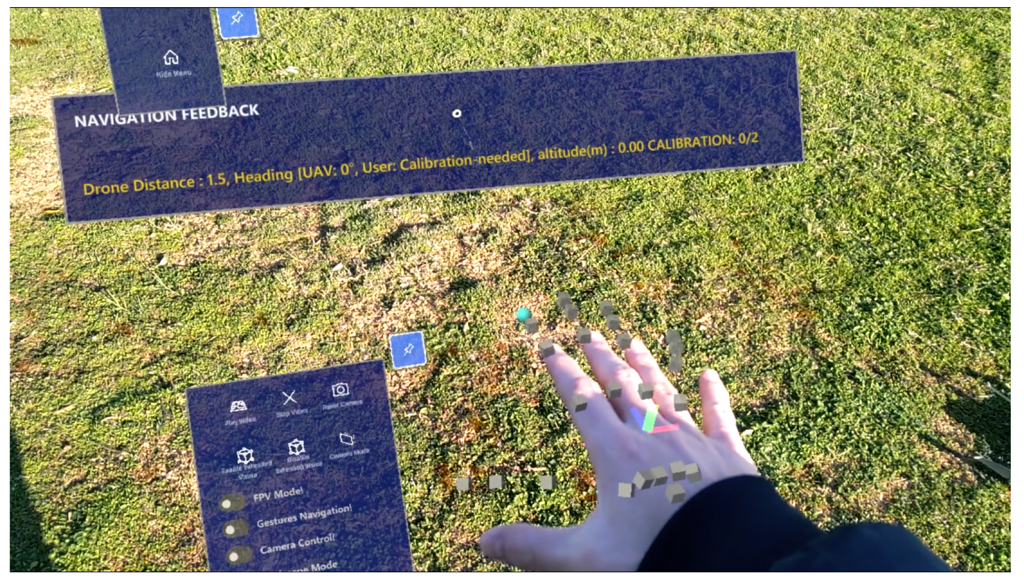
AR feedback and visualization: GUI elements and various visualization features were added in the AR application to provide feedback and various controls. Emphasis was given to creating an easy-to-use application and increasing the SA of the user. In more detail:
- –
Visualization of the virtual hand joints overlaying on top of the user hands, making it possible for the user to directly check if his/her hands are correctly perceived by HoloLens (
Figure 4).
- –
Drone visualization based on the drone tracking module. A virtual drone is overlaid on top of the real drone so that the user is aware of the drone’s relative position even if it is not in a direct line of sight (e.g., behind a wall or building) or too far to be easily visible with a naked eye.
- –
An extensive virtual menu that includes all high level commands and toggles for enabling the application features is present in the lower part of the application view. The menu can be be hidden in order to not obstruct the user’s field of view.
- –
A navigation feedback panel is placed at the top part of the application’s window. In the feedback panel, the current perceived navigation commands are listed alongside with other drone- and user-related information such as the drones’s flying altitude and horizontal distance from the user, the drone heading, and the user heading.
3.5. UAV Interface Application
An application was developed to act as a communication bridge between the DJI drone and the rest of the system architecture. We chose the Android platform since it was the most mature and versatile Mobile SDK platform DJI had to offer at the time of development. The app is installed on an Android smartphone connected to the remote controller via a USB cable. The drone connects to the remote controller via DJI’s proprietary communication protocol, OcuSync, while the smartphone connects to the rest of the system by WiFi or a commercial mobile network. The app’s primary responsibilities are:
Receiving control commands from Kafka and forwarding them to the drone;
Collecting the drone’s IMU readings, aggregating them to estimate its position, and posting this to Kafka at regular intervals;
Sending the drone’s live video feed directly to the HoloLens via network sockets.
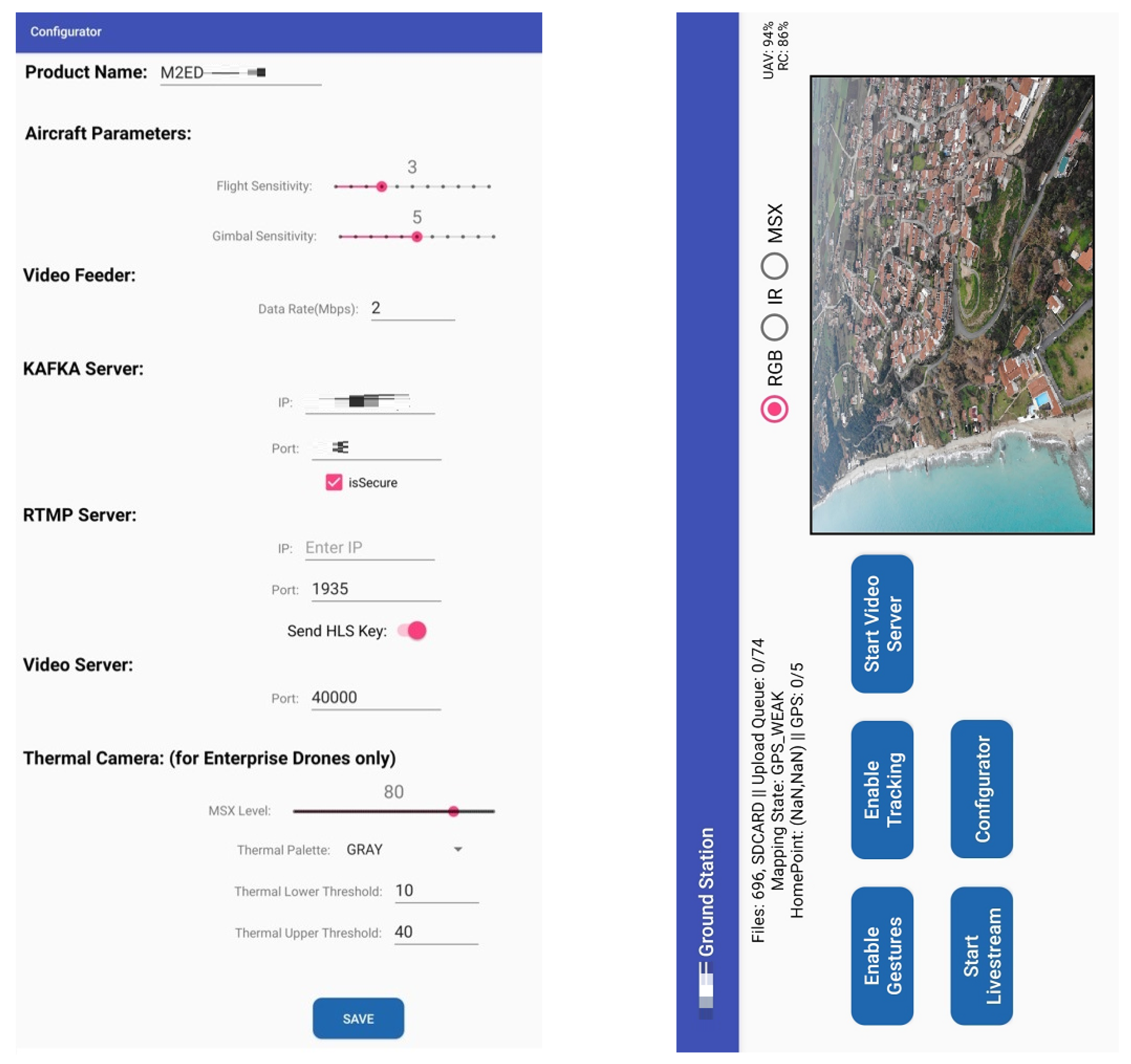
The application, depicted in
Figure 5, displays practical information (e.g., battery status of the aircraft and of the remote controller), along with a live view of the drone’s camera feed. Buttons are also present to perform various actions. The “Configurator” button exposes the user to a settings page shown on the left pane of
Figure 5, where several parameters can be configured, including connection settings, the sensitivity of the drone to gesture commands, and infrared visualization options.
4. Methodology
The realization of the presented solution can be broken down into five tasks, each regarding a different aspect of the gesture control or the AR visualization pipeline:
Gesture definition, in which an appropriate set of hand gestures was selected to control the drones, meeting requirements relating both to usability and control. This was the focus of earlier work ([
32]), refined and updated for the current work;
Gesture acquisition, in which users’ hand gestures must be captured, interpreted, translated to flight or camera control commands, and forwarded to the drone via the UAV interface Android app;
Drone position tracking in AR, in which the drone’s motions must be tracked in reference to the virtual world, based on aggregated IMU reading and optionally improved by visual cues;
Calibration, in which the virtual environment must be aligned with the real world, in terms of both translation and rotation, so that virtual objects can be displayed in the context of the environment. Calibration is necessary both for tracking and displaying the drone in AR and displaying a contextualized video feed, which depends on tracking;
Video transmission and visualization, in which the drone’s video feed must be transmitted to the HoloLens and displayed in AR in (near) real time, via the UAV interface Android app.
The rest of this section describes in detail each of these five tasks, presenting the methodologies followed, noting weaknesses, and outlining possible future improvements.
4.1. Gesture Definition
4.1.1. Requirements and Considerations
In order to develop a viable alternative drone control system, it should allow users to perform the same motions as a regular handheld remote: pitch, roll, yaw, throttle, and their combinations, as well as camera motions. Similarly, it should allow users to define the sensitivity of each command, and by extension, the amplitude of the corresponding motion.
Designing Natural User Interfaces (NUI), such as gestures, some additional requirements must be taken into account to achieve intuitive interaction. Peshkova et al. [
33] explained that the gestures should be related to each other while following a single metaphor. In the same study, the use of multi-modal interaction, such as a combination of gesture and speech commands, is encouraged in order to increase naturalness. Hermann et al. [
11] additional requirements were highlighted including avoidance of non-ergonomic positions (as described in [
34]) and the presence of some form of feedback. In an AR environment, several forms of feedback can be integrated in the real-world view of the user as overlaid virtual objects.
Hence, UAV gesture control has three primary aims:
To provide an easy-to-learn and intuitive interface;
To be physically comfortable and ergonomic;
To allow the full extent of drone motions, including combination motions and variable velocities.
4.1.2. Gesture Vocabulary
In a previous user study and survey [
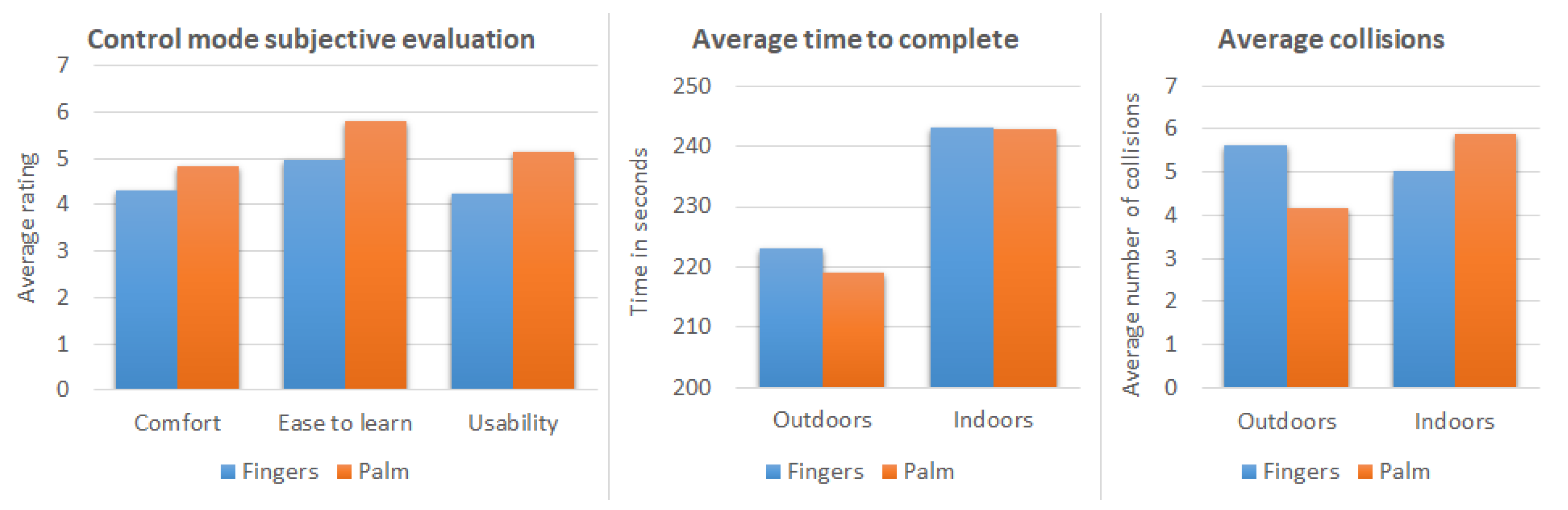
32], we tested two sets of gesture vocabularies, a finger-based and a palm-based vocabulary in a simulated drone navigation environment. Users were required to navigate a virtual drone in an outdoor and an indoor environment. In the finger-based mode, each gesture is defined by which fingers are extended, and the velocity value is defined by the pointing direction of a selected extended finger. In the palm-based mode, the operator uses the positioning and orientation of his/her open palm (all finders extended) to control the drone. The subjective study results showed a clear user preference for the palm-based control, which was described as more comfortable and easier to learn and use. The objective metrics showed faster task completion using the palm-based controls, however, finger-based control offered more precise navigation. The overall objective score showed that the palm-based control has a slightly better performance.
The study results are aligned with findings in [
33] that intuitive NUIs should be based on a common metaphor. In this case, the metaphor chosen is that the drone corresponds to the user’s hand, and hence mimics and follows all its movements. Therefore, raising the hand up higher will correspond to an ascend (increase throttle) command; a tilt of the hand will correspond to the drone assuming a similar angle (pitch and/or roll); a horizontal rotation will correspond to yaw; and so on. This metaphor, validated by the user study, addresses the first aim of gesture control.
The second aim of gesture control is to avoid non-ergonomic, physically stressing hand gestures. It may be noted that even easy-to-perform gestures can be tiring when performed repeatedly or may oblige users to hold their hand/arm steady in the same height for a long time. In order to avoid the latter, we applied a relative gesture vocabulary based on a varying reference position. One key gesture is used as a reset and calibration command. When the user performs this key hand gesture, the current hand pose is set as the neutral (resting) position, and all following gestures are interpreted relative to this. This allows users to chose the resting position that is most comfortable to them and even define new resting positions in preparation for certain maneuvers.
Hence, a user wishing to command the drone to ascend may define a low resting position, allowing her to move her hand higher with no discomfort. Later, in preparation for a descent, a higher resting position may be chosen so that the user can lower her hand easily. The reset and calibration command is tied to the user opening the palm and extending the fingers. Hence, after a brake and stop command (closed fist), a new resting position is always defined before the user issues a new command. While the hand is closed and no commands are issued, users can position their hand in preparation for the next gestures safely.
This palm-based gesture set was expanded in later work to include take-off and landing gestures [
35]. Similar to a handheld remote, these gestures are mapped to hand positions assumed and held over a couple of seconds. To differentiate them from the other UAV control commands, take-off and landing use an upwards-facing palm. The full palm gesture vocabulary used for drone navigation is shown in
Figure 6. Moreover, the user’s other hand can be used to control the camera gimbal, where the same set of gestures are mapped to camera pitch and yaw.
It can be noted that the selected gesture set can be used to perform any UAV motion achievable with the traditional handheld remote. Velocities of UAV commands are mapped directly to the angles or distances relative the resting position, allowing for a continuous control ranging from no motion at all to fast motion. Combination motions, such as pitching forward while yawing a little to the left and slowly descending are easily achievable. This can be further substantiated, as the human hand, like all real-world objects, has six degrees of freedom (translation and rotation along three axes), while a quadcopter’s control has four (pitch, roll, yaw, and throttle). This demonstrates that movements are independent of each other and can hence be freely combined. Naturally, the same holds for the camera-controlling hand. Therefore, the third aim of gesture control is addressed.
4.1.3. Drone Control Features
The drone control module was implemented following an agile development process; starting from a set of basic features, continuous testing and user feedback led to the refinement of the user requirements. Initially, the hand gesture drone control was implemented and three additional features, hand gesture camera control, periscope mode, and high-level voice control commands were added.
The primary task was to accurately navigate the drone using the selected palm gestures. It should also be noted that when no gesture is performed or when the user hand is not visible, no command is sent, and the drone stops. Inside the AR application, visual cues were displayed providing feedback to facilitate the navigation task. Drone navigation is performed using the user’s right hand by default, however, this can be a parameter.
In the hand gesture camera control, the unassigned user hand, by default the left hand, is used for controlling the view direction of the drone’s camera. This feature is controlling the camera gimbal, which is able to perform 2DoF movements: rotation up/down (pitch) and rotation right/left (yaw). The gesture vocabulary used for camera control is similar to the vocabulary for drone navigation, however, there are less defined gestures since the camera’s possible movements are fewer; by tilting the open palm left or right, the camera turns to the corresponding direction in the vertical axis while, by tilting the palm up or down, the camera rotates in the corresponding direction in the horizontal axis.
Periscope mode is an additional form of gesture control, which does not involve the use of hands but it is based on the user’s head direction. When Periscope mode is enabled, the drone viewing direction follows the user’s head direction in real time. For example, when the user rotates his head to look 90° east, the drone rotates to the exact same direction. Periscope is an auxiliary feature allowing for a quick and intuitive inspection of the surrounding environment that has collected very positive reviews from the end-users.
Finally, voice commands are used to perform high-level commands such as resetting the camera direction. Voice commands are completely optional, as all the commands can be alternatively performed by buttons and controls available in the virtual application menu, however, they offer a multi-modal tool of interaction and at the same time allow the user to use their hands for controlling the drone or perform an other task and at the same time dictate the desired command using speech.
4.2. Gesture Acquisition
4.2.1. Background
Our early research [
32] into gesture acquisition for drone control considered two different hardware peripherals: the AvatarVR glove (
https://avatarvr.es/, accessed on 20 December 2021), a wearable with embedded IMU and touch sensors, and the LeapMotion controller (
https://developer.leapmotion.com/, accessed on 20 December 2021), an infrared LED and camera device. The former was found to falsely report finger curl when rotating the hand, which made it incompatible with the open hand metaphor described in the previous subsection; hence, it was discarded for the current application. The LeapMotion controller performed well in a lab setting but the lack of wireless portability (as it needs a USB connection) and its inability to track hands in an sunlit outdoor environment were important limiting factors. However, it served well for the initial development phase of the solution, as it includes a Unity API. Most of the gesture recognition and interpretation functions were based on the LeapMotion API and later adapted for the HoloLens.
Google’s MediaPipe Hands [
36] was also considered for purely RGB-camera-based gesture acquisition. This has proved robust in a wide range of lighting conditions, making it suitable both indoors and outdoors. However, as it is compatible with Unix and Android systems only, the integration of this modality into the HoloLens has not been realized. It has been used with a webcam for training on a computer simulator, and it could be considered for future developments on different AR devices or standalone gesture control applications not including AR visualization.
4.2.2. Gesture Acquisition and Interpretation in HoloLens 2
Gesture recognition for the palm-based control in HoloLens 2 utilized the MRTK Unity3D plugin and more specifically, the Hand-tracking API. The MRTK hand-tracking API did not provide (at least during the time of the development) high-level functions for recognizing extended fingers or an open/closed palm. The main values provided are handedness (left or right hand), joint transform (the position and orientation in the 3D space), and joint type (e.g., index tip, index distal, metacarpals, etc.). As a result, the development of palm navigation had to start by implementing a Gesture Recognizer component able to detect an open palm gesture in real-life conditions where fingers are quite often occluded or not completely straight, etc. The gesture recognizer component is based on the work provided by Rob Jellinghaus (
https://github.com/RobJellinghaus/MRTK_HL2_HandPose/, accessed on 20 December 2021), but is heavily modified to adjust to our case needs. The code takes into account finger–eye alignment and co-linearity between finger pairs to cope with finger occlusions. It also uses ratios between different hand’s parts instead of absolute measurements to be able to handle different hand sizes. Since in the palm-based control we are only interested in two classes of gestures, open/extended palm and closed palm, the gesture detector does not have to be very precise in recognizing gesture details. For that reason, the gesture classification criteria are modified to match the needs of the application: The criterion for an open palm classification is the detection of an extended thumb and at least three extended fingers. This way, the recognizer is more sensible in recognizing an open palm gesture, which is the main state of interest.
When the Gesture Recognizer module detects an open palm, the hand joints’ information (position and rotation) is processed by the Palm Navigation module that calculates the navigation commands (pitch, yaw, roll, throttle, and take off/landing) and their amplitude (or velocity values) based on the hand joints’ current and past rotation angles. As mentioned in
Section 4.1.2, in order to avoid physical stress, the reference null position can change every time the user performs the reset command (closed palm gesture). The next open palm position after the reset command corresponds to the reference position and the joint angles and position at that point are stored as the neutral (or zero) transforms for the future commands.
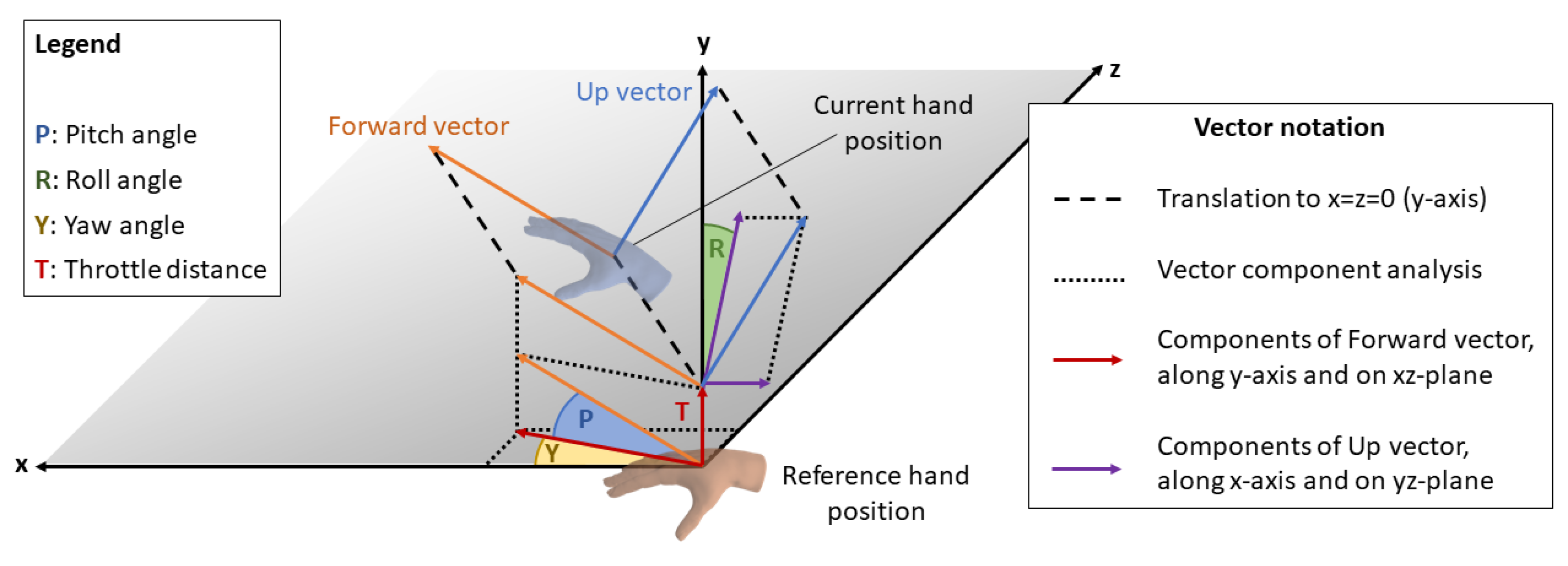
In particular, three components of the hand’s position are relevant: the hand’s Up normal vector, perpendicular to the palm; the hand’s Forward normal vector, perpendicular to Up, and facing forward, along the direction of the middle finger; and the hand’s vertical position. An overview of the vectors and their correspondence with the drone control values is shown in
Figure 7. Interpretation is relative to the reference hand position. The current position’s normals are translated to the
y-axis and analyzed into components. Pitch is computed by the angle of the Forward vector to the
xz-plane. Yaw is tied to the angle of the Forward vector’s
xz-component to the
x-axis. Roll is computed by the angle of the Up vector’s
yz-component to the
y-axis. Throttle is proportionate to the vertical (
y-axis) distance between the current position and the reference. All commands allow for a “neutral zone”, so that minor or involuntary motions are not translated to a drone command.
4.3. Drone Position Tracking in AR
Drone tracking is used to monitor the physical location of the drone during a flight. In our case, this information is utilized in two different ways: to assist monitoring and piloting the drone when it is out of line of sight or too distant to distinguish it clearly using a virtual drone marker in the AR environment and to position the AR video canvas according to the drone’s location and orientation and hence in context with the real environment.
Drones are commonly equipped with two positioning mechanisms: GPS and IMU. GPS is commonly used to provide an approximate location-based satellite communication. However, it presents two major drawbacks: It is only available outdoors, and its precision is limited, ranging from 2.5 m to 10 m or more [
14]. This precision can be inadequate for flights that require precision. Hence, the presented system relies on IMU readings. The DJI SDK offers no access to low-level IMU measurements; instead, it combines the readings from multiple sensors, including magnetometer, gyrospope, and accelerometer measurements to report the estimated velocity of the drone, at regular intervals. Velocity is reported in a North–East–Down (NED) coordinate system, with an origin point at the drone’s starting location. The reported velocity measurements
V are collected by the Android UAV interface app, multiplied by the interval time
T to yield translations in distance, and summed to provide the estimate position of the drone
D at time
t, relative to its starting point:
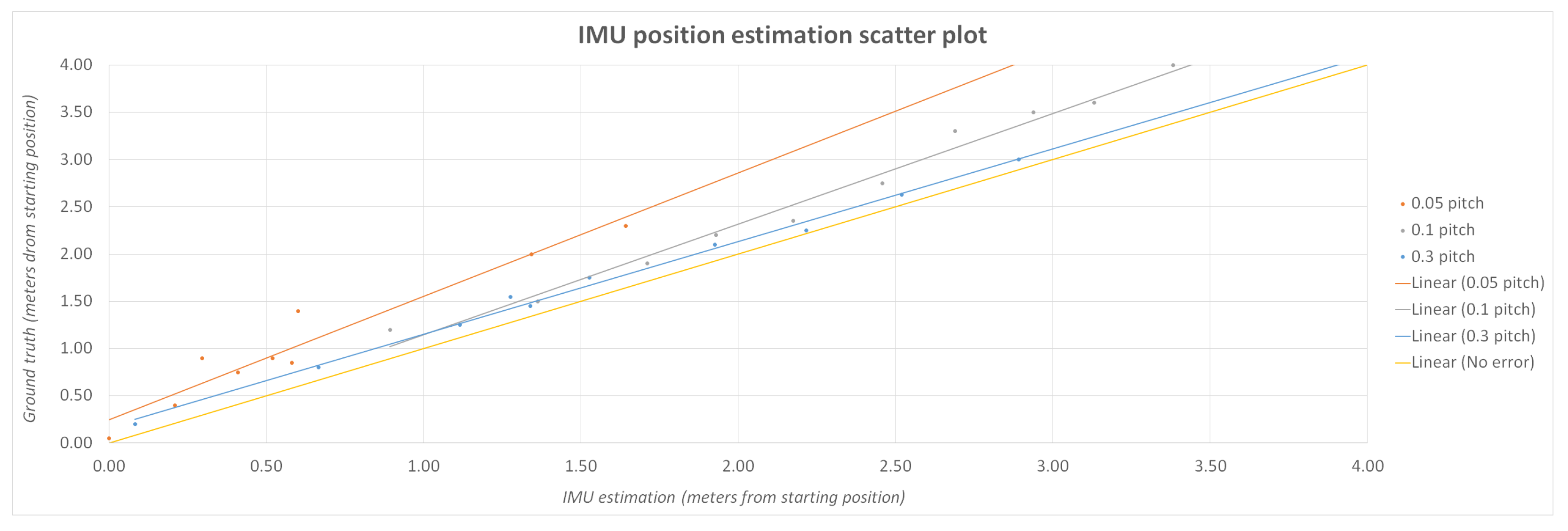
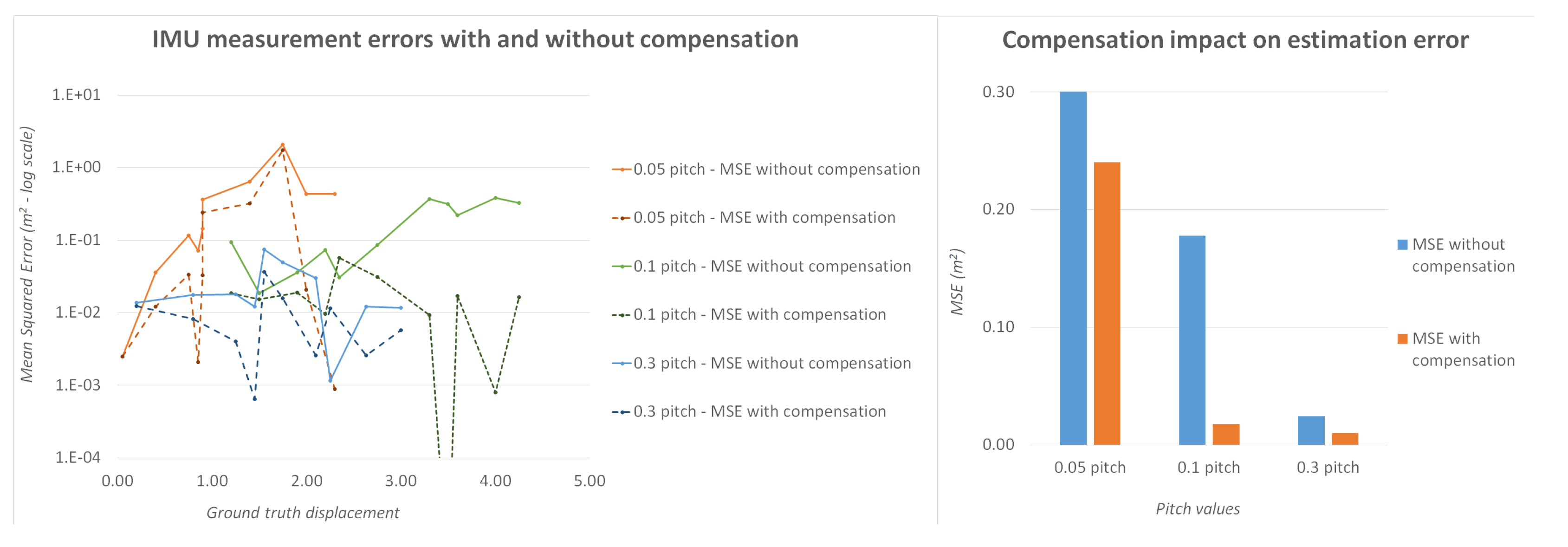
The above assumes that between reports, velocities remain constant, which is not the case when performing maneuvers. However, with a 100 ms reporting period, these errors are negligible. A more significant drawback to this procedure is the low precision — two decimal places—at which velocities are reported by the SDK. This makes for an average error of
m/s. Naturally, this becomes more significant at lower velocities, where it can account for up to 16% of the real velocity. Even without compensation, the position as derived by aggregated IMU readings is more accurate than GPS over short periods of time and short distances. With the error-correcting compensation described in
Section 5, the accuracy improves significantly and is adequate for both locating and guiding the drone, perhaps excluding very precise maneuvering in tight spaces. For longer distances, GPS reading can be used correctively to ensure that the aggregated IMU drift is capped to the GPS precision.
The application posts the position related data presented in JSON format on the Kafka broker. The post frequency is four times per second in order to consume less network and computational process power. On the client side, the HoloLens application connects to the Kafka broker and consumes these messages on a specific topic. Based on the message information, it renders a virtual drone-like object into the augmented reality environment, overlaying the position of the real drone. In order to achieve this coupling, a prior calibration process is required to align the HoloLens’s internal coordinate system with that of the drone.
4.4. Calibration of the AR Environment
Tracking a real object in augmented reality and visualizing it in context with the real environment requires a correspondence between two different coordinate systems: one based in the real world and one based in the virtual world, which will be superimposed on the real world to provide the AR graphics. As outlined in
Section 4.3, the drone’s position is continuously estimated based on aggregated IMU readings and its heading is supplied directly by its onboard compass. Hence, the calculated pose is expressed in relation to a system of coordinates with the drone’s starting location as an origin point and its
y-axis aligned with the north.
The HoloLens does not use its internal compass to orient its internal coordinate system, and the compass readings are not readily available to Unity apps. Therefore, the AR elements, including the virtual drone marker and the video panel, must be expressed in relation to the internal coordinate system, with an origin and y-axis direction equal to that at the user’s location and heading, respectively, at the time of launching the application.
In order to link the two coordinate systems and place the virtual drone marker in the corresponding position of the physical drone and, by extension, for the video panel to be displayed correctly in context with the environment, a calibration procedure should be performed. The calibration process aims to calculate the relative translation and rotation between the two systems. Even though both real and virtual objects are mobile in 3D, with six DoF, the drone’s altitude is tracked and reported independently via its altimeter. Hence, this can be viewed as a 2D problem of axis rotation and translation.
Keeping elementary linear algebra in mind [
37], for two 2D coordinate systems with the same alignment (no rotation) and an offset of
, if
are the coordinates of a point in one system, then its coordinates in the rotated system will be:
Meanwhile, for two 2D coordinate systems with the same origin point (no translation) and a rotation of
, if
are the coordinates of a point in one system, then its coordinates in the rotated system will be:
In the generic case of both translation and rotation, we have:
Hence, using the real-world drone and its virtual marker in the AR coordinate system as the common point, we can link the two coordinate systems following a calibration procedure. The following text describes both the default, manual calibration method and two vision-based alternatives.
4.4.1. Manual Two-Step Calibration
The manual two-step calibration method relies on users performing the HoloLens’s “air tap” gesture to mark the drone’s location to the HoloLens app.
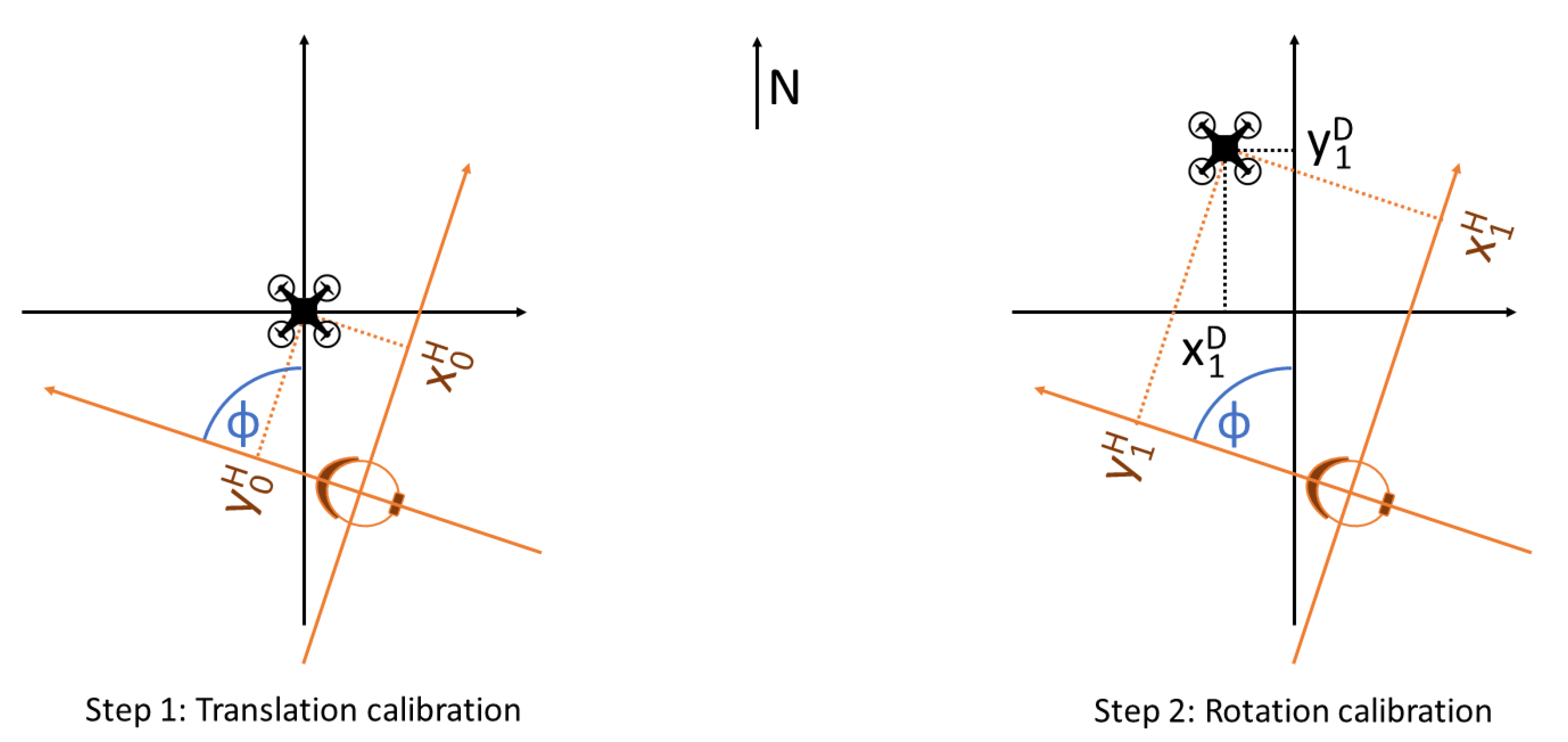
In the generic case, the HoloLens app will launch with the user some distance away from the drone and facing a random direction, forming an angle
with the north.
Figure 8 shows the two different coordinate systems and the devices’ starting location with different colors. In order to translate coordinates from one system to the other, we need to calculate the coordinates of the origin of one with respect to the other (translation vector) and the angle
, which can form the rotation matrix.
During the first step of calibration, the drone has not yet moved, and the user air-taps its present (starting) position, as shown in
Figure 8 on the left. That position’s HoloLens coordinates
are then captured and stored and form the translation vector.
To capture the rotation angle, the drone is moved from its starting position. The new position’s HoloLens coordinates
are captured with a second air-tap. At the same time, the new position’s Drone coordinates
are calculated based on the aggregated IMU readings.
Figure 8, on the right, shows this second step. Hence, Equation (
4) yields:
The only unknown being
, the above can yield:
Therefore, Equation (
6) can be used to obtain rotation angle
, given any non-zero displacement
. Knowing both translation and rotation, any future drone-system coordinates can be translated to HoloLens system coordinates to allow visualization in AR.
4.4.2. Visual Drone Pose Estimation
Instead of relying on user information (air-taps) a drone’s relative pose (position and orientation) may be inferred from visual data, captured live from the HoloLens’s onboard camera. To that end, we propose a method that exploits the latest advances in deep learning to automatically retrieve the 6DoF pose of a drone from a single image. An early version of this architecture, described in more detail in [
23], uses a CNN encoder backbone followed by three fully connected layers that output two predictions, one for the translation components and one for the rotation. The translation prediction uses an
loss, while the rotation prediction aims to minimize the angular difference
. The two loss functions are weighted by a balancing hyperparameter
and combined to form the training loss function.
The newest update employs a state-of-the-art architecture, HRNet [
38], as a landmark regression network to predict the eight landmark image positions. Then, we retrieve the pose using the predicted 2D–3D correspondences. However, this approach does not permit end-to-end training, as the pose retrieval step is not differentiable. Towards this end, we exploited the recently introduced BPnP algorithm [
39], which has been proved to be effective for the pose estimation task [
40].
For training our models and evaluating their performance, we have compiled and made publicly available the UAVA dataset (also in [
23]), an extensive set of synthetic, photorealistic images of drones in indoor and outdoor environments, which provides ground truth annotations of 2D keypoints, pose, depth maps, normal maps, and more.
Accurate visual drone pose estimation can automate and simplify the calibration process, as both distance (step 1) and orientation (step 2) can be estimated by a single image, automatically, without user input. Visual recognition of the drone and its pose by HoloLens is robust at distances of a maximum of 5–10 m, depending on drone model and size. In addition, this method can be used to periodically correct the position computed by the aggregated IMU readings, offsetting IMU drift and any other errors. With the current version specifications of HoloLens, such an algorithm cannot run continuously in real time. However, even sparse inferences, performed every 5–15 s, can keep IMU drift at a minimum and improve tracking.
4.4.3. QR Code Reading
An alternative to the visual estimation of the drone’s pose is to rely on QR codes pasted on the physical drones. The HoloLens provides a built-in capability to detect and read QR codes robustly. Hence, by pasting a QR code on top of the drone, the HoloLens can detect its starting position (analogous to step 1 in the manual calibration process) automatically, with no need of human intervention. While the air-tap determines a single point and hence provides only position information, the QR code is an object, and its detection can provide both position and orientation. Hence, in conjunction with the heading provided by the drone’s compass, both steps of the manual calibration process can be completed in a single QR code read.
Naturally, a QR code pasted on a drone’s top is easily readable at short distances (perhaps a maximum of 2 m), i.e., while the drone is landed and the user stands close to it. Hence, while this method can provide fast and automated calibration, it cannot be used for correcting the drone’s position during flight and offsetting IMU drift, as is the case with
Section 4.4.2.
4.5. Video Transmission and Visualization
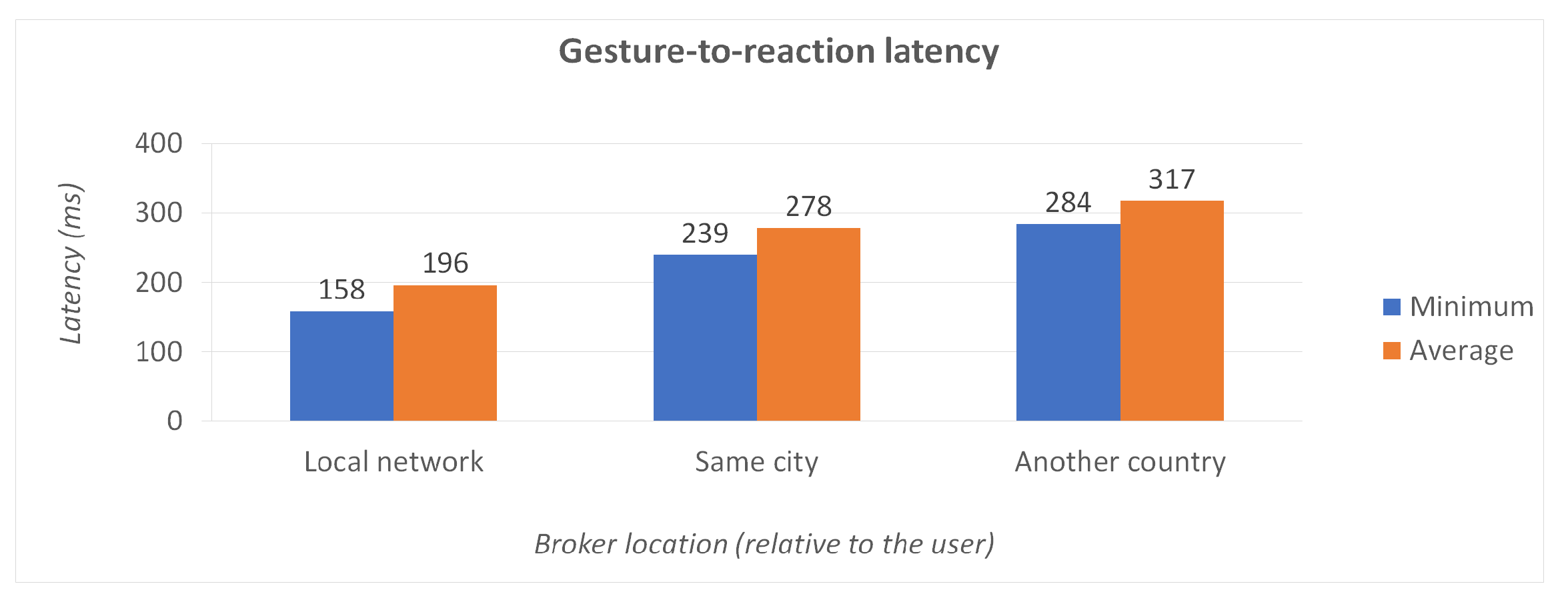
When implementing the live streaming feature of the drone’s camera video feed to HoloLens 2, we had to consider specific requirements regarding latency and frame rate. In order for the video stream to be usable for piloting, it had to be low in latency and high in frame rate. Overall latency is the sum of two values: the latency from the drone to the remote controller, which depends on the drone manufacturer and the streaming protocols used, and the latency from the remote controller to the HoloLens, via the UAV interface app, which depends on the presented solution. In this case, DJI uses OcuSync for video transmission, which adds a nominal latency of 120 to 270 ms. The following text focuses on the latency between the remote controller and the HoloLens.
Ideally, the overall latency should be low enough to allow easy and safe control based solely on the video feed (e.g., in FPV mode) and frame rate should be high enough for the video to be viewable as a continuous stream. Therefore, we set targets for <350 ms overall latency (hence 120 ms for the Android-to-HoloLens latency) and >15 frames per second (FPS).
4.5.1. Video Streaming
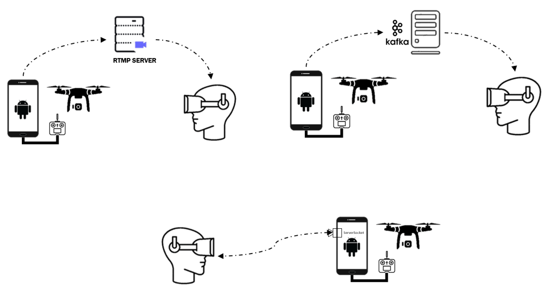
Several methods and streaming protocols were considered for the transmission of live video to the HoloLens, including Real-Time Messaging Protocol (RTMP), Real-time streaming protocol (RTSP), sending frames as individual messages through Kafka, and direct connection via network sockets.
RTMP is a flash-based video streaming protocol routing the video stream through a server and supported natively by the DJI SDK. However, RTMP induces high latency, ranging from one to several seconds, depending on the the network conditions and server location and capabilities. This makes RTMP a good choice for non-reactive video watching (e.g., for a spectator) but unsuitable for remote control. RTSP and HLS (Http Live Streaming) exhibit similar behavior, and hence they were discarded for use in the presented solution.
Sending video frames through Kafka was implemented in an effort to simplify the architecture by routing all data through the same hub (Kafka). Two flavors were tested: sending encoded frames directly from the UAV interface app to the HoloLens and decoding the frames first on Android and then forwarding the decoded data to the HoloLens. Naturally, the first flavor minimizes bandwidth requirements, while the second minimizes the processing strain on the HoloLens. On a local (Wi-Fi) network, bandwidth is less of a concern, hence latency was reduced when streaming decoded frames. However, the frame rate has proved to be too low (at about 11 FPS) in both cases. This is attributed to the HoloLens using a REST API to connect to Kafka (as there are no clients available for UWP), which induces an overhead for each message request. Therefore, this approach was also discarded.
The solution finally selected made use of Network Sockets. This type of connection is Point-to-Point, meaning that once the connection is established, no additional overhead is required for the flow of data. With this implementation, in contrast to the two previous methods, there is no intermediate server between the drone and the HoloLens. The Android device running the UAV interface app acts as a server with the HoloLens being the client. To test this approach, we connected the drone and the HoloLens to alleviate network bottlenecks. We measured the Android-to-HoloLens latency below 100 ms and the frame rate exactly 30 FPS, which is the native frame rate of the drone’s camera. Since both requirements were met, this method is the most appropriate for piloting the drone through the live video feed from the camera.
4.5.2. Video Decoding
On the HoloLens side, the decoding process starts when the connection has been established. For the purposes of the decoding task, we have implemented a dedicated library using the FFmpeg tool, namely, Decoder, to handle video frames. The library has been implemented as a dynamic-link library for the Microsoft Windows operating system and built for UWP architecture compatible with HoloLens 2.
The Android app feeds the AR app with h.264 encoded frames. In the AR application decoding and visualization of the received video frames are handled in two background processing threads. The first thread runs the Decoder module while the second thread is responsible for the frame visualization. Decoding is performed in a 30Hz (native) rate while rendering in 15Hz for performance reasons and efficient management of computational resources. Rendered frames are displayed in a virtual projection panel. In contextualized video mode, this panel is placed in front of the drone, in the direction its camera is facing, while in FPV mode it is centered on the user’s field of view.
During development, different methods of video streaming were implemented and tried (as shown in
Figure 9). These included RTMP streaming (top left), sending video frames through Kafka (top right), and a direct connection using web sockets (bottom). The latter was finally selected, as it yields the lowest latency and requires no intermediaries.
6. Conclusions and Future Steps
6.1. Conclusions
In this paper, we have presented a unified system for AR-integrated drone use, encompassing gesture control, tracking, and camera feed visualization in context with the user’s environment. We have outlined the overall system architecture as well as individual components, described the mechanics of the vital tasks necessary for its function and conducted both objective and subjective evaluation experiments. Different aspects of the proposed solution were evaluated, with the results described in
Section 5, including gesture selection and usability; drone responsiveness in terms of time lag; drone tracking accuracy and the efficacy of compensation; and video transmission quality.
Although the presented implementation focused on specific hardware (the HoloLens and DJI drones), the underlying logic and architecture are modular and not tied to the current hardware choices. As mentioned in the
Section 4.2, the same gesture control methodology has been implemented and tested successfully with alternative hardware, including a regular webcam or smartphone camera. Hence, integration with different drone models or AR hardware is possible and mostly a matter of implementation.
The presented system has largely achieved its objectives, and future plans include both refinements and wider validation. In particular, gesture control has proved both intuitive and accurate, providing the same level of control as a traditional handheld remote. However objective evaluation with real drones (i.e., not a simulator) has not yet been completed and is scheduled for the near future. This should be in comparison with the handheld remote controller, with pilots being asked to place the drone in a specified position. Measurements could include accuracy (distance from the specified position) and time (to achieve that position). In addition, more complex drone behaviors can be tied to either specific gestures or virtual buttons in future implementations; such behaviors can include flying in a circular or other pattern or returning to land either at the take-off location or near the user.
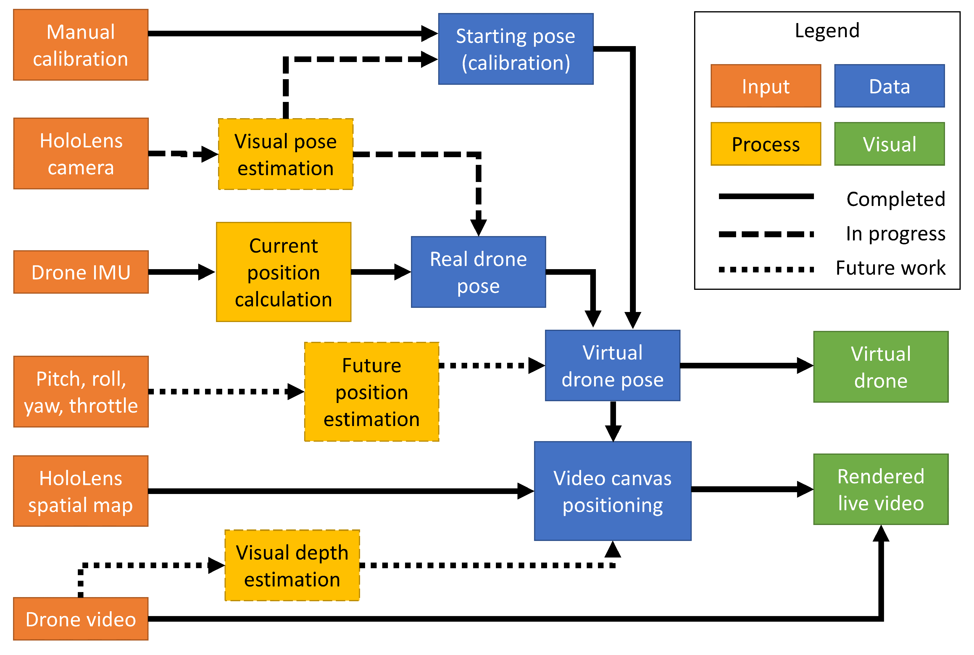
6.2. AR Tracking and Visualization Present and Future Vision
Work into the AR components—drone tracking, calibration, and visualization—of the presented solution is still ongoing. While the currently developed system is a working prototype, a number of possible future improvements have been outlined and planned for the medium term.
Figure 14 presents our vision for such future additions.
Regarding calibration, the working prototype uses a manual, two-step calibration, which can prove both tiresome and challenging for inexpert users. Hence, work is already in progress to calibrate initial drone pose with a largely automated, visual method. Two options are currently considered, as outlined in the
Section 4.4: a visual drone pose estimation AI and the reading of QR codes pasted on the drones. The former should also provide intermittent visual recognition of the drone during flight, correcting the IMU readings and eliminating any accumulated drift.
In addition, it can be noted that the position as tracked in AR will always lag some time behind that of the real drone, as IMU readings must be collected, read, and aggregated, a position estimated and forwarded to the HoloLens and there displayed. A future module could raw input from the flight control of the drone (pitch, roll, yaw, and throttle) and estimate a future position for the drone, offsetting the lag of data transmission and processing.
Finally, the AR video canvas is currently displayed a set distance in front of the virtual (tracked) drone. However, the actual distance between the drone and the objects in its field of view might range from a couple of meters to hundreds. A depth estimation algorithm could gauge this distance and position the video canvas appropriately, for a more realistic display in context with the environment.


 ,
, 


