Article

Simultaneous Astronaut Accompanying and Visual Navigation in Semi-Structured and Dynamic Intravehicular Environment

1
College of Aerospace Science and Engineering, National University of Defense Technology, Changsha 410073, China
2
College of Control Science and Engineering, Zhejiang University, Hangzhou 310000, China
3
Huzhou Institute, Zhejiang University, Huzhou 313000, China
*
Author to whom correspondence should be addressed.
Drones 2022, 6(12), 397; https://doi.org/10.3390/drones6120397
Submission received: 17 October 2022 / Revised: 25 November 2022 / Accepted: 3 December 2022 / Published: 6 December 2022
(This article belongs to the Special Issue Advances in UAV Detection, Classification and Tracking)

Abstract

:
The application of intravehicular robotic assistants (IRA) can save valuable working hours for astronauts in space stations. There are various types of IRA, such as an accompanying drone working in microgravity and a dexterous humanoid robot for collaborative operations. In either case, the ability to navigate and work along with human astronauts lays the foundation for their deployment. To address this problem, this paper proposes the framework of simultaneous astronaut accompanying and visual navigation. The framework contains a customized astronaut detector, an intravehicular navigation system, and a probabilistic model for astronaut visual tracking and motion prediction. The customized detector is designed to be lightweight and has achieved superior performance (AP@0.5 of 99.36%) for astronaut detection in diverse postures and orientations during intravehicular activities. A map-based visual navigation method is proposed for accurate and 6DoF localization (1~2 cm, 0.5°) in semi-structured environments. To ensure the robustness of navigation in dynamic scenes, feature points within the detected bounding boxes are filtered out. The probabilistic model is formulated based on the map-based navigation system and the customized astronaut detector. Both trajectory correlation and geometric similarity clues are incorporated into the model for stable visual tracking and trajectory estimation of the astronaut. The overall framework enables the robotic assistant to track and distinguish the served astronaut efficiently during intravehicular activities and to provide foresighted service while in locomotion. The overall performance and superiority of the proposed framework are verified through extensive ground experiments in a space-station mockup.

1. Introduction

Human resources in space are scarce and expensive due to launch costs and risks. There is evidence that astronauts will become increasingly physically and cognitively challenged as missions become longer and more varied [1]. The application of artificial intelligence and the use of robotic assistants allow astronauts to focus on more valuable and challenging tasks during both intravehicular and extravehicular activities [2,3,4]. Up to now, several robotic assistants of various types and functionalities have been developed to improve astronauts’ onboard efficiency and help perform regular maintenance tasks such as thermal inspection [5] and on-orbit assembly [6]. These robots include free-flying drones designed to operate in microgravity such as Astrobee [7], Int-Ball [8], CIMON [9], IFPS [10], BIT [11], and more powerful humanoid assistants such as Robonaut2 [12] from NASA and Skybot F-850 [13] proposed by Roscosmos. Although different designs and principles are adopted, robust intravehicular navigation and the ability to work along with human astronauts constitutes the basis for their onboard deployment.
Firstly, to provide immediate service, the robotic assistant should be able to detect and track the served astronaut with high accuracy and efficiency. The recent advances in deep learning have made it possible to solve this problem. Extensive research has been carried out in terms of pedestrian detection [14] and object detection [15,16] by predecessors based on computer-vision techniques. However, the problem of astronaut detection and tracking has some distinctive characteristics due to the particular onboard working environment. On one hand, astronauts can wear similar uniforms and present diverse postures and orientations during intravehicular activities. This can cause problems for general-purpose detectors that are designed and trained for daily life scenes. On the other hand, the relatively fixed and stable background, and the limited range of motion in the space station are beneficial to customizing the astronaut detector. In terms of astronaut motion tracking and prediction, the problem cannot be simply resolved by calibrating intrinsic parameters as with a fixed surveillance camera. The robotic assistant can move and rotate at all times in the space station. Both the movement of the robot and the motion of the served astronauts will change the projected trajectories on the image plane. The trajectories must be decoupled so that the robot can distinguish the actual movement of the served astronauts. Our previous works [17,18] have mainly focused on the astronaut detection and tracking problem from a simplified fixed point of view.
An effective way to decouple motion is to incorporate the robot’s 6DoF localization result so that the measured 3D positions of the astronauts can be transformed into the inertial world frame of the space station. Many approaches can be applied to achieve 6DoF localization in the space station. SPHERES [19] is a free-flying research platform propelled by cold-gas thrusters in the International Space Station (ISS). A set of ultrasonic beacons are mounted around the experimental area to provide localization with high efficiency, which resembles a regional satellite navigation system. However, the system can only provide the positioning service within a cubic area of 2 m and may suffer from the problem of signal occlusion and multi-path artifact [20]. The beacon-based approach is more suitable for experiments than service-robot applications. Int-Ball [8] is a spherical camera drone that can record HD videos under remote control currently deployed in the Japanese Experiment Module (JEM). It aims to realize zero photographing time by onboard crew members. Two stereoscopic markers are mounted on the airlock port and the entrance side for in-cabin localization. The accuracy of the marker-based method depends heavily on observation distance. When the robot is far away from the marker, the localization accuracy drops sharply. Moreover, if the robot conducts large-attitude maneuvering, the makers will move out of the robot’s vision, and an auxiliary localization system has to take over.
From our perspective, the robotic assistant should not rely on any marker or auxiliary device other than its proprietary sensors for intravehicular navigation. This ideology aims to make the robot’s navigation system an independent module and to enhance its adaptability to environmental changes. The space station is an artificial facility with abundant visual clues, which can provide ample references for localization. Astrobee [7] is a new generation of robotic assistants propelled by electric fans in the ISS. It adopts a map-based visual navigation system which does not rely on any external device. An intravehicular map of the ISS is constructed to assist the 6DoF localization of the robot [21]. The team has also studied the impact of light-intensity variations on the map-based navigation system [22]. However, they did not consider the coexistence of human astronauts and the problem of dynamic scenes introduced by various intravehicular activities. These problems are crucial for IRA to work in the manned space station and to provide satisfactory assistance.
To resolve the problem, this paper proposes the framework of simultaneous astronaut-accompanying and in-cabin visual navigation. The semi-structured environment of the space station is utilized to build various registered maps to assist intravehicular localization. Astronauts are detected and tracked in real time with a customized astronaut detector. To enhance the robustness of navigation in dynamic scenes, map matches within the bounding boxes of astronauts are filtered out. The computational workload is evenly distributed within a multi-thread computing architecture so that real-time performance can be achieved. Based on the robust localization and the customized astronaut detector, a probabilistic model is proposed for astronaut visual tracking and short-term motion prediction, which is crucial for the robot to accompany the served astronaut in the space station and to provide immediate assistance. Table 1 compares our proposed approach and existing methods in the literature. The incorporation of the intravehicular navigation system enables astronaut visual tracking and trajectory prediction from a moving point of view, which is one of the unique contributions of this paper.
The rest of this paper is organized as follows. In Section 2, the problem of astronaut detection in diverse postures and orientations is discussed. In Section 3, we focus on the problem of map-based intravehicular navigation in both static and dynamic environments. In Section 4, the astronaut visual tracking and short-term motion prediction model is presented. Experiments to evaluate the overall design and comparative analyses are discussed in Section 5. Finally, we summarize in Section 6.

2. Astronaut Detection in Diverse Postures and Orientations

In this section, we address the problem of astronaut detection during intravehicular activities, which is an important component of the overall framework. A lightweight and customized network is designed for astronaut detection in diverse postures and orientations, which achieved superior performance after fine-tuning with a homemade dataset.

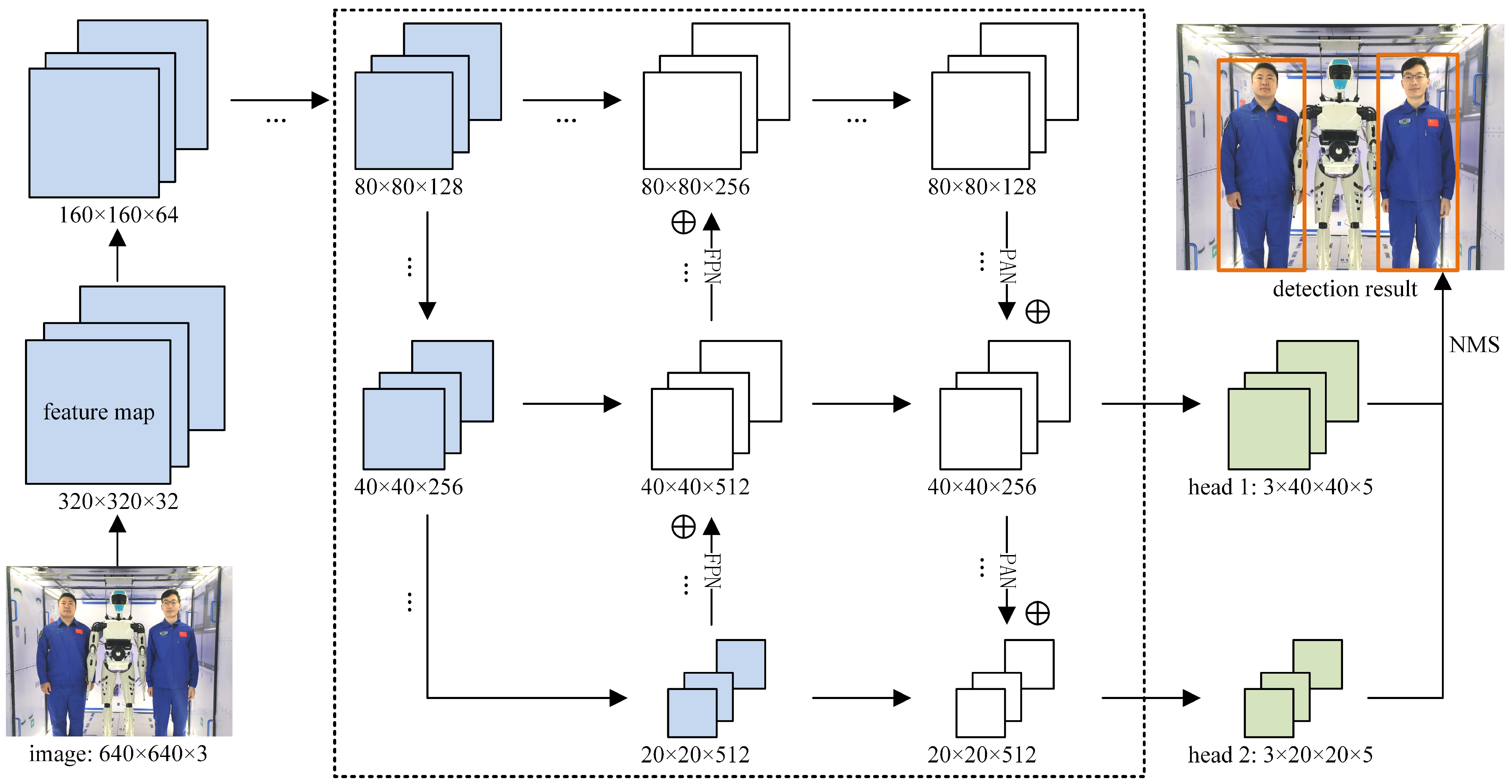
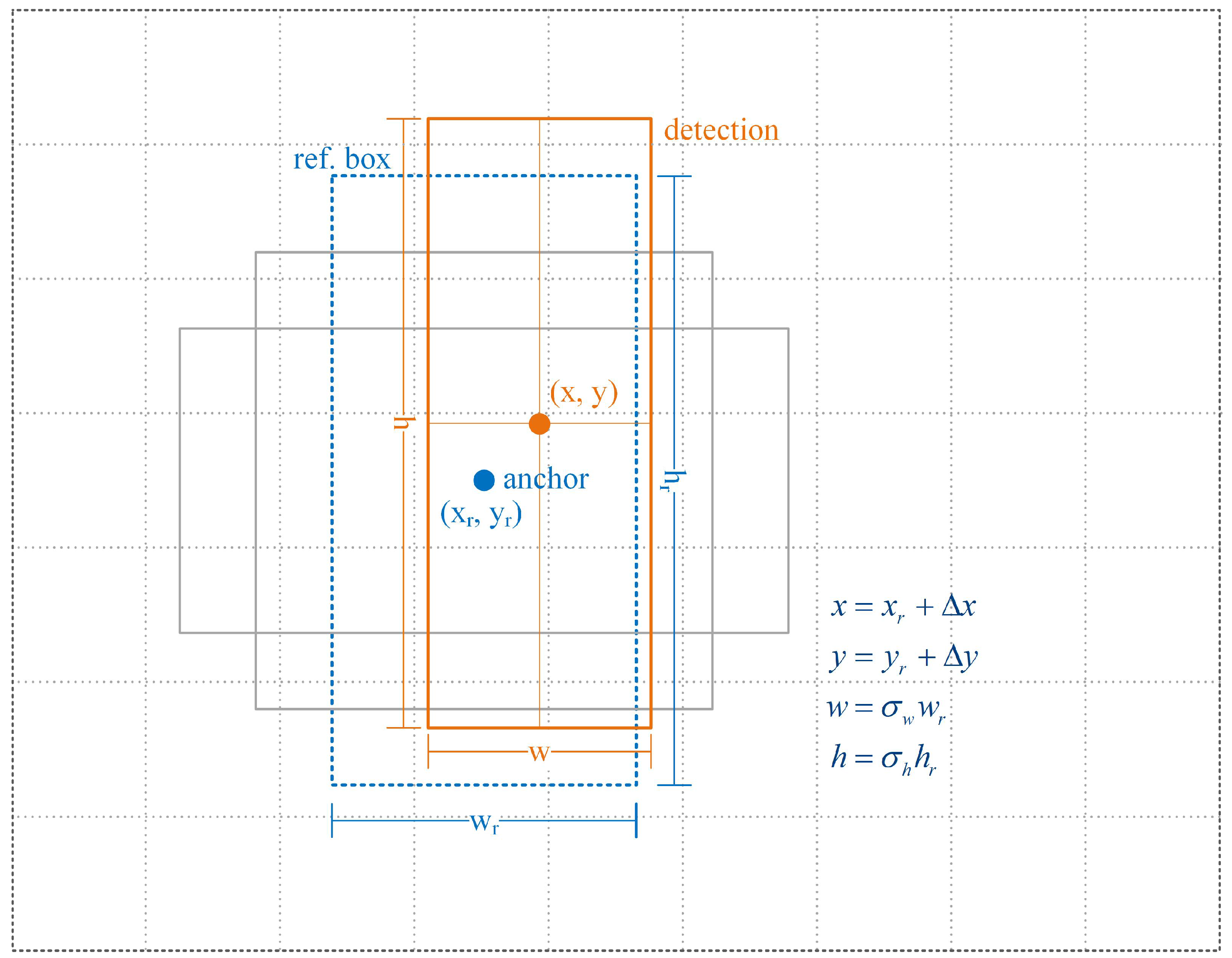
2.1. Design of the Customized Astronaut-Detection Network

The special intravehicular working environment has introduced some new features to the astronaut-detection problem, which can be summarized as
(1)
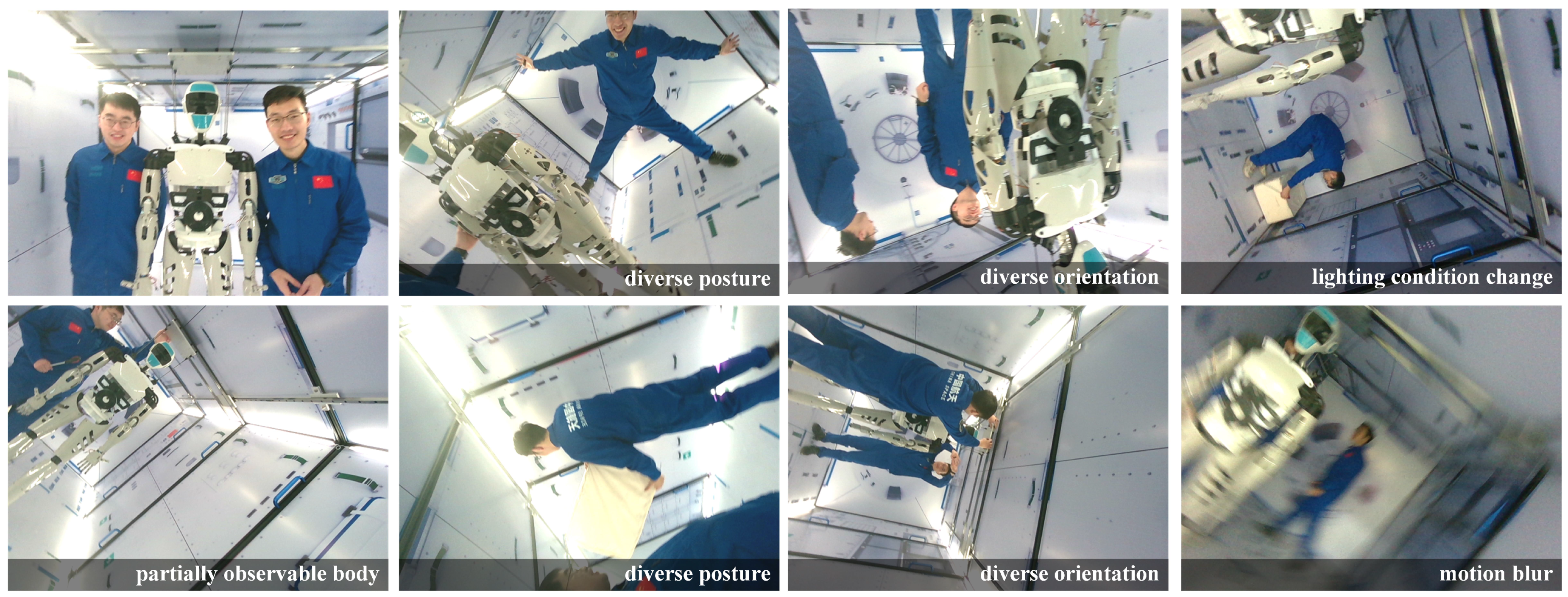
Astronauts can present diverse postures and orientations during intravehicular activities, such as standing upside down and climbing with handrails.
(2)
Astronauts may wear similar uniforms, which are hard to distinguish.
(3)
Images can be taken from any position or orientation by IRA in microgravity.
(4)
It is possible to simplify the astronaut detector while maintaining satisfactory performance by utilizing the relatively fixed and stable background and the limited range of motion in the space station.
(5)
There is a limited number of crew members onboard the space station at the same time.
To achieve satisfactory performance, the astronaut-detection network should be equipped to cope with the above features and be lightweight enough to provide real-time detections. Anchor-based and one-shot object-detection methods [15,23], such as the Yolo network, are widely used in pedestrian detection for their balance between accuracy and efficiency. However, these networks do not perform well in the astronaut-detection task. Many false and missed detections can be found in their results. This poor performance is due to the fact that the structures of those networks are designed for general-purpose applications and the parameters are trained with daily life examples. There lies a gap between the networks’ expertise and the actual application scenarios.
To fill the gap, we proposed a lightweight and customized astronaut-detection network based on the anchor-based technique. The main structure of the network is illustrated in Figure 1, where some repetitive layers are collapsed for better understanding. Input to the network is the color image taken by the robot with a resolution of 640 × 480. Layers in blue are feature-extraction modules characterized by abundant residual blocks [24], which can mitigate the notorious issue of vanishing and exploding gradients. The raw pixels are gradually compressed to the feature maps of 80 × 80, 40 × 40, and 20 × 20, respectively. Layers in the dashed box apply structures of feature pyramid network (FPN) and path aggregation network (PAN) [25] to accelerate feature fusion in different scales. The residual blocks, FPN, and PAN structures have introduced abundant cross-layer connections, which improves the network’s overall fitting capacity. Green layers on the right-hand side are the anchor-based detection heads that output the final detection results after non-maximum suppression.
Considering the limited number of served astronauts and their possible scales on the images, only two detection heads are designed, which also reduces the parameters and improves the network’s real-time performance. The detection head with a 20 × 20 grid system is mainly responsible for astronaut detection in proximity, while the other head with a 40 × 40 grid system mainly provides smaller scale detections when astronauts are far away. As shown in Table 2, three reference bounding boxes of different sizes and shapes are designed for each anchor to adapt to the diverse postures and orientations of astronauts during intravehicular activities. A set of correction parameters ( Δ x , Δ y , σ w , and σ h ) are estimated with respect to the most similar reference boxes to characterize the final detection, as shown in Figure 2. Each reference box also outputs the confidence p of the detection. The two detection heads provide a total of 6000 reference boxes, which is sufficient to cover all possible scenarios in the space station. To summarize, the astronaut-detection problem is modeled as a regression problem fitted by a lightweight and customized convolutional network with 7.02 million trainable parameters.

2.2. Astronaut-Detection Dataset for Network Fine Tuning

The proposed network cannot maximize its performance before training with an appropriate dataset. General-purpose datasets such as the COCO [26] and the CrowdHuman [27] dataset mismatch the requirements. The incompatibility may be found in the crowdedness of people, the diversity of people’s postures and orientations, and the scale of the projections, etc. Even though various data-augmentation techniques can be employed in the training process, it is difficult to mitigate the mismatches between the daily life scenes and the actual working scenarios in the space station.
To address the problem, we built a space-station mockup of high fidelity on the ground, and created a customized dataset for astronaut detection and visual tracking. Volunteers are invited to imitate the intravehicular activities of astronauts in the space-station mockup. During data collection, we constantly moved and rotated the camera so that bodies in the captured images show diverse perspectives. As shown in Figure 3, the proposed dataset incorporated a variety of scenes such as diverse postures and orientations of astronauts, partially observable human bodies, illumination variations, and motion blur. In total, 17,824 labeled images were collected, where 12,000 were used as the training dataset while the remaining 5824 were used as the testing dataset.

2.3. Network Pre-Training and Fine Tuning

The astronaut detector is trained in two steps. In the pre-training phase, the network is fed with a cropped COCO dataset for 300 epochs. The cropped dataset is made by discarding crowd labels and labels that are too small or not human from the COCO 2017 dataset. The pre-training process will improve the detector’s generalization ability and reduce the risk of over fitting by incorporating large numbers of samples. In the second step, the pretrained model is fine-tuned with the customized astronaut-detection dataset for 100 epochs to obtain the final detector with superior accuracy. The objective function is kept the same in both steps and is formulated as a weighted sum of the confidence loss and the bounding-box regression loss.
L o s s = 1 A i = 1 A j = 1 G L c o n f p i , p ^ i j + λ c ^ i j L l o c l i , l ^ i j
where L c o n f ( · ) is the cross-entropy confidence loss, L l o c ( · ) is the bounding-box regression loss related to the prediction l i and the matched target l ^ i j where the CIOU [28] criterion is adopted, c ^ i j is 1 if the match exists, λ is the weight parameter set to 1, G is the number of ground truth label, and A is the total number (6000) of reference bounding boxes.
After the two-step training, the proposed detector achieved superior detection accuracy (better than 99%) and recall rate (better than 99%) in the testing dataset, which outperforms the general-purpose detector and the pre-trained detector. Detailed analyses will be discussed in Section 5.
The proposed astronaut detector will play an important role in the robust intravehicular visual navigation in the manned space station to be discussed in Section 3, and support the astronaut visual tracking and motion prediction to be discussed in Section 4.

3. Visual Navigation in Semi-Structured and Dynamic Environments

In this section, we focus on the problem of robust visual navigation in the semi-structured and dynamic intravehicular environment, which is the other component of the overall framework. The problem is addressed using a map-based visual navigation technique that does not rely on any maker or additional device. The semi-structured environment makes it unnecessary to use a SLAM-like approach to explore unknown areas, and a map-based method is more practical and reliable. Moreover, compared with possible long-term environmental changes, the ability to cope with instant dynamic factors introduced by various intravehicular activities is more important.

3.1. Map-Based Navigation in Semi-Structured Environments

A proprietary RGB-D camera is used as the only sensor for mapping and intravehicular navigation. The RGB-D camera can not only provide color images with rich semantic information, but also the depth value of each pixel, which can improve the perception of distance and eliminate scale uncertainties.
(A)
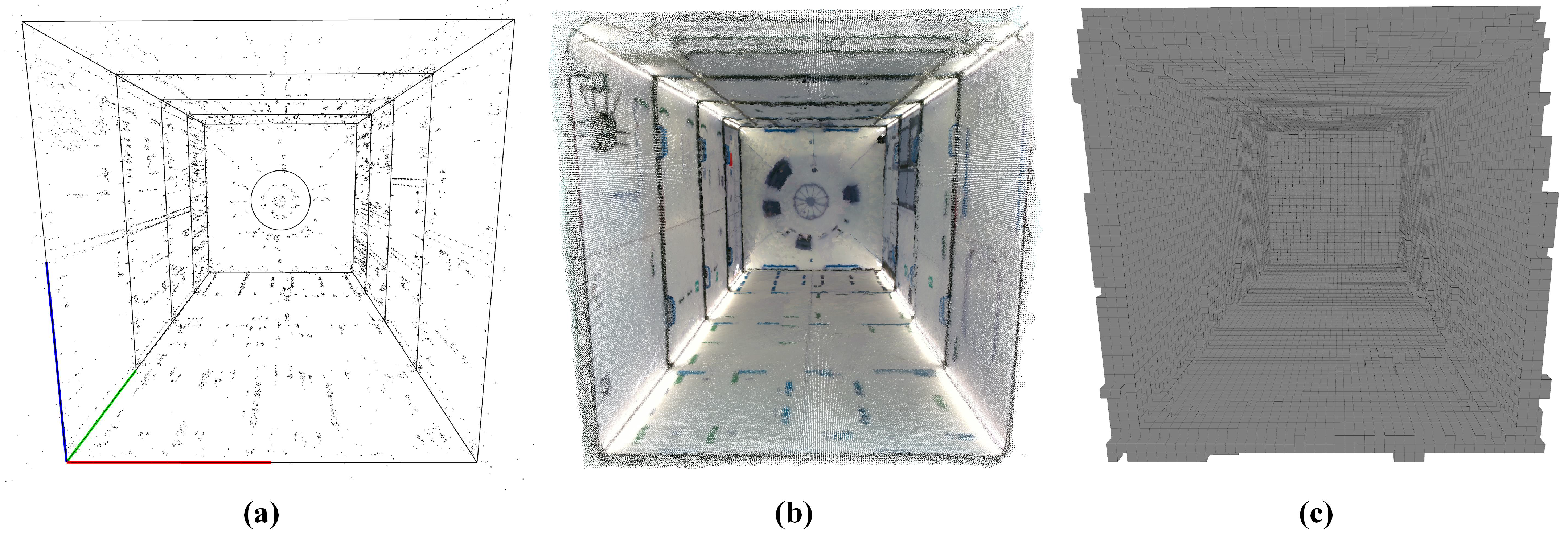
Construction of the visual navigation map
In the mapping phase, the RGB-D camera is used to collect a video stream inside the space-station mockup from various positions and orientations. The collected data covered the entire space so that few blind areas are introduced. Based on the video stream, three main steps are utilized to build the final maps for intravehicular navigation.
(1)
Build initial map using standard visual SLAM technique.
(2)
Maps are optimized to minimize the distortion and the overall reprojection error.
(3)
The optimized maps are registered to the space station with a set of known points.
The initial map can be constructed using the Structure from Motion (SFM) technique [29] or standard visual SLAM technique. In our case, a widely used keyframe-based SLAM method [30] is adapted to build the initial point cloud map of the space station. The very first image frame is set as the map’s origin temporarily. The point-cloud map contains plenty of distinguishable map points for localization and keyframes to reduce redundancy and assist feature matching. By searching enough associated map points in the current image, the robot can obtain its 6DoF pose with respect to the map.
In the second step, the map is optimized several times to minimize the overall measurement error, so that the map’s distortion can be reduced as much as possible, and higher navigation accuracy can be achieved. The optimization problem is summarized as the minimization of reprojection error of associated map points in all keyframes.
X j , R k , t k = arg min k = 1 K j = 1 M ρ c k j x k j π R k X j + t k 2
where X j is the coordinate of the jth map point, R k and t k are the rotational matrix and translational vector of the kth keyframe, π ( · ) is the camera projection function with known intrinsic parameters, x k j is the pixel coordinate of the matched feature point in the kth keyframe with respect to the jth map point, and c k j is 1 if the match exists. ρ ( · ) is the robust Huber cost function to reduce the impact of error matches.
The constrained space in the space station allows for minimal distortion of the maps after global optimization as compared with applications in large-scale scenes. In the third step, a set of points with known coordinates are utilized to transform the optimized map to the world frame of the space station. Various types of maps can be constructed accordingly for different purposes such as localization, obstacle avoidance and communication [31]. Figure 4 presents three typical maps registered to the space-station mockup. All maps have an internal dimension of 2 × 4 × 2 m. The point-cloud map shown in Figure 4a contains, in total, 12,064 map points with distinctive features, and 209 keyframes which are used to accelerate feature matching for pose initialization and re-localization. Figure 4b,c illustrates the dense point-cloud map and the octomap [32] constructed concurrently with the sparse point-cloud map. The clear definition and the straight contours of the mockup in the dense point cloud and the distinguishable handrails in the octomap proved the high accuracy of the maps after global optimization (2), which guarantees the accuracy of the map-based navigation system.
(B)
Map-based localization and orientation
With prebuilt maps, two steps are carried out for intravehicular localization and orientation. In the first step, the robot tries to obtain an initial estimate of its 6DoF pose from scratch. This is achieved by comparing the current image with each similar keyframe in the sparse point-cloud map. Initial pose will be recovered using a PnP solver when enough 2D–3D matches are associated. With an initial pose estimation, local map points are then projected to the current image to search more 2D–3D matches for pose-only optimization, which will provide a more accurate localization result. The pose-only optimization problem can be summarized as the minimization of reprojection error with a static map.
{ R , t } = arg min j = 1 M ρ c j x j π R X j + t 2
where R and t are the rotational matrix and translational vector of the robot with respect to the world frame, x j is the pixel coordinate of the matched feature point with respect to the jth map point, and c j is 1 if the match exists.
When the robot succeeds to localize itself for several consecutive frames after initialization or re-localization, frame-to-frame velocity is utilized to provide the initial guess to search map points, which saves time and helps improve computational efficiency.

3.2. Robust Navigation during Human–Robot Collaboration

The robotic assistant usually works side by side with human astronauts to provide immediate service. In the constrained intravehicular environment, astronauts can take a field of vision in front of the robot. Astronauts’ various intravehicular activities can also occlude the map points and introduce dynamic disturbance to the navigation system. In such a condition, the robot may be confused to search enough map points for stable in-cabin localization. The poor localization will, in turn, create uncertainties for the robot to accomplish various onboard tasks.
To address the problem, we proposed the integrated framework of simultaneous astronaut accompanying and visual navigation in the dynamic and semi-structured intravehicular environment. The framework can not only solve the problem of robust navigation in dynamic scenes during human–robot collaboration, but also assist in tracking and predicting the short-motion of the served astronaut to provide more satisfactory and foresighted assistance.
As shown in Figure 5, the framework adopts a multi-thread computing architecture to ensure real-time performance. The main thread in the red dashed box is mainly responsible for image pre-processing and in-cabin visual navigation, whereas the sub thread in the blue dashed box is mainly responsible for astronaut detection, visual tracking, and trajectory estimation. Specifically, while the main thread is working on frame registration and feature extraction, the sub thread tries to detect astronauts in the meantime. The first-round information exchange between the two threads is carried out at this point. Then, feature points within the detected bounding boxes are filtered out to avoid large areas of disturbances to the visual navigation system.
While the main thread is working on 6DoF pose initialization and optimization, the sub thread is idle and can perform some computations such as astronaut skeleton extraction. The second-round information exchange i8s carried out once the main thread has obtained the localization result. The optimized 6DoF pose together with the detected bounding boxes are utilized for astronaut visual tracking and motion prediction in the sub thread, which will be discussed in Section 4.
The computational burden of the proposed framework is evenly distributed where the main thread uses mainly CPU resources and the sub thread consumes mainly GPU resources. The overall algorithm is tested to run at over 30 Hz with a GS66 laptop (low-power i9@2.4 GHz processor and RTX 2080 GPU for notebook).

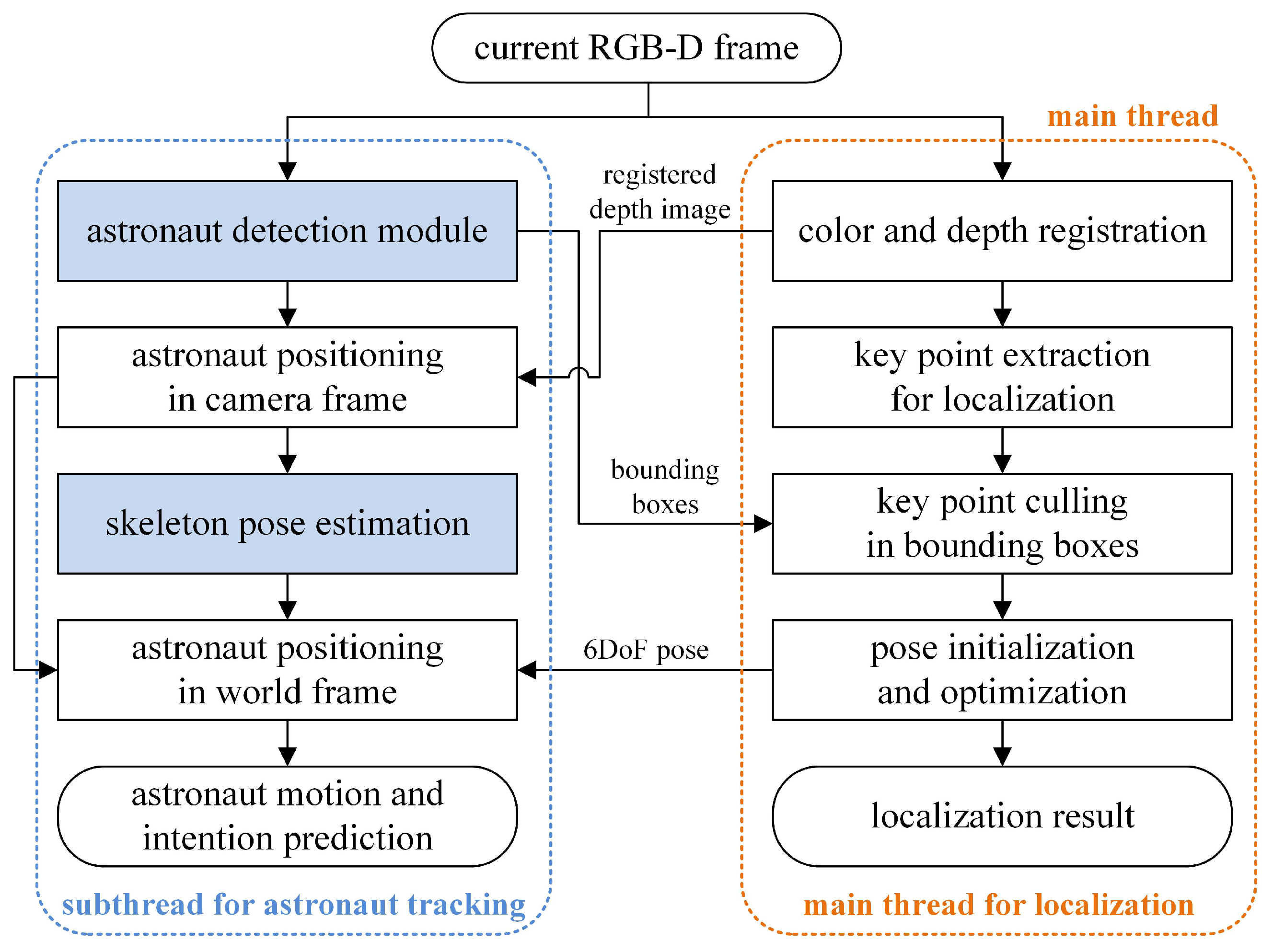
4. Astronaut Visual Tracking and Motion Prediction

Astronaut visual tracking and motion prediction help the robot track and identify the served astronaut and provide immediate assistance when required. The solution to the problem is based on the research into astronaut detection in Section 2 and the research into robust intravehicular navigation in Section 3.
Specifically, the astronaut visual-tracking problem is to detect and track the movement of a certain target astronaut in a sequence of images, which is formulated as a maximum a-posteriori (MAP) estimation problem as
i = arg max P k p β i k , β t k 1 , i = 1 , 2 , , M
where M is the number of detected astronauts in the current (or kth) frame; β i k and β i k 1 are the ith bounding box in the current frame and the target to be matched in the previous frame, respectively; and P k ( · β i k , β t k 1 ) defines the probability of the match. We seek to find the bounding box with the largest posterior probability. If no bounding box is matched for a long time or the wrong bounding box is selected, the tracking task fails.
The posterior probability in Equation (4) is determined by a variety of factors. For example, when the 3D position of β i k is close to the predicted trajectory of the served astronaut, or the bounding boxes overlap, there is a high match probability. On the contrary, when the 3D position of β i k deviates from the predicted trajectory or the geometry mismatches, the probability will be small. According to the above factors, the overall posterior probability is decomposed into the trajectory correlation probability P predicton k , and the geometric correlation probability P geometry k and other clues P others k include identity identification probability.
i = arg max P k p β i k , β t k 1 = arg max P predicton k p β i k P geometry k p β i k , β t k 1 P others k p β i k , β t k 1
(A)
Matching with predicted trajectory
The served astronaut’s trajectory can be estimated and predicted using the astronaut detection result in the image flow and the robot’s 6DoF localization information.
Firstly, the 3D position of the astronaut in the robot body frame [ x b , y b , z b ] T is obtained using the camera’s intrinsic parameters. The coordinates are averaged over a set of points within a small central area in the bounding box to reduce the measurement error. Then, by incorporating the 6DoF pose R , t of the robot (3), the astronaut’s 3D position can be transformed to be represented in the world frame of the space station [ x w , y w , z w ] T .
x w y w z w = R T x b y b z b t
The space station usually keeps three axes stabilized to the earth and orbits every 1.5 h. We assume the space station to be an inertial system when modeling the instant motion of astronauts. The motion is formulated as a constant acceleration model for simplicity. For example, when the astronaut moves freely in microgravity, a constant speed can be estimated and the acceleration is zero. When the astronaut contacts with the surroundings, a time-varying acceleration can be estimated by introducing a relatively large acceleration noise in the model. The above motion model and corresponding measurement model are defined as
x w k = A x w k 1 + w z k = H x w k + v
where A R 9 × 9 is the state transition matrix that determines the relationship between the current state x w k R 9 and the previous state x w k 1 , vector z k is the measured 3D position of the astronaut represented in the world frame, H R 3 × 9 is the measurement matrix, w is the time-invariant process noise to characterize the error of the simplified motion model, and v is the time-invariant measurement noise determined by the positioning accuracy of the served astronaut. The process and measurement noise are assumed to be white Gaussian with zero means and covariance matrices of Q and R, respectively.
The nine-dimentional state vector contains the estimated position, velocity, and acceleration of the served astronaut represented in the world frame as
x w k = x w k y w k z w k v x , w k v y , w k v z , w k a x , w k a y , w k a z , w k R 9
The trajectory of the served astronaut can be predicted with the above constant acceleration model. The update interval is kept the same as the frequency of the overall astronaut-detection and visual-navigation framework at 30 Hz.
x w k = A x w k 1 P k = A P k 1 A T + Q
where P is the state covariance matrix. We propagate Equation (9) for a few seconds to predict the short-term motion of the served astronaut.
With estimated trajectories, a comparison is made between the prediction and each bounding box in the current image frame. There would be a high correlation probability if the 3D position of a certain bounding box is close to the predicted trajectory of the target astronaut. The trajectory correlation probability is defined as
P predicton k p β i k = e α 0 z i k x w k ( 1 : 3 )
where z i k is the measured position of the astronaut in the ith bounding box and α 0 is a non-negative parameter.
Once the match is verified together with other criteria, the measurement will be used to correct the motion model of the target astronaut.
K k = P k H T ( H P k H T + R ) 1 x w k = x w k + K k ( z k H x w k ) P k = ( I K k H ) P k
(B)
Matching with geometric similarity
Besides trajectory correlation, the geometric similarity of the bounding boxes can also provide valuable information for visual tracking. The overall algorithm runs at 30 Hz, and, thus, we assume few changes between consecutive frames to be introduced. Many criteria can be used to characterize the similarity between bounding boxes. We selected the most straightforward IOU (intersection over union) criterion. When a certain bounding box in the current image frame overlaps heavily with the target in the previous frame, there would be a high matching probability. The geometric correlation probability is defined as
P geometry k p β i k , β t k 1 = e α 1 ( 1 I O U )
where α 1 is a non-negative parameter, and a larger α 1 will give more weight to the IOU criterion.
(C)
Matching with other clues
Some other clues can also be incorporated to assist astronaut visual tracking. For example, face recognition is helpful for initial identity confirmation and tracking recovery after long-time loss. The corresponding posterior probability is formulated as
P others k p β i k , β t k 1 = 1.0 , matched 0.5 , not sure 0.0 , not matched
During the experiments, we only applied the trajectory and geometric correlation probabilities into the framework. The face-recognition part is out of the scope of this paper, and can be referenced from our previous work [18].

5. Experimental Results and Discussion

Experiments were carried out to evaluate each component of the proposed framework in Section 5.1 (astronaut detection) and Section 5.2 (visual navigation) respectively. The overall performance is verified and discussed in Section 5.3.

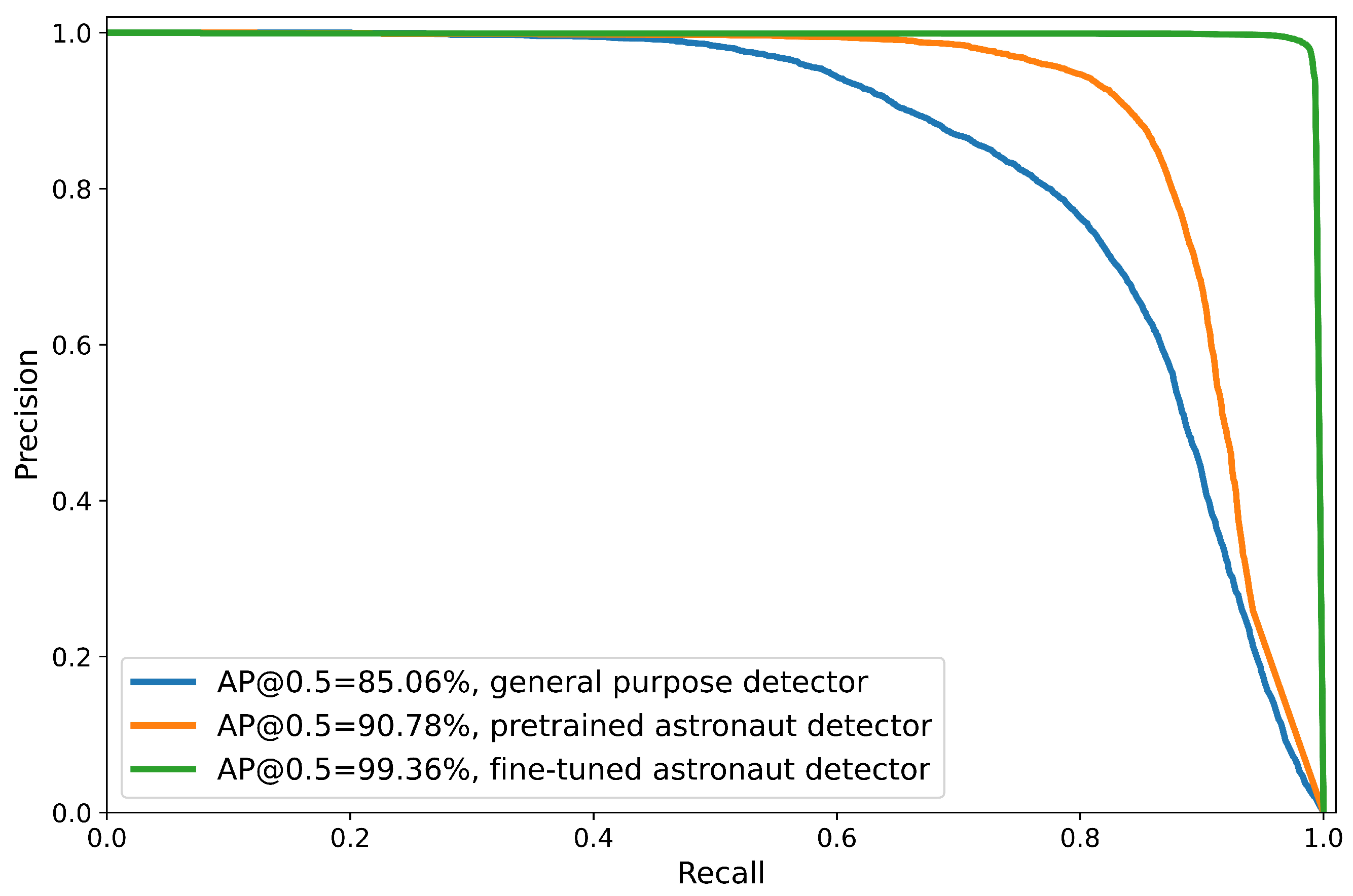
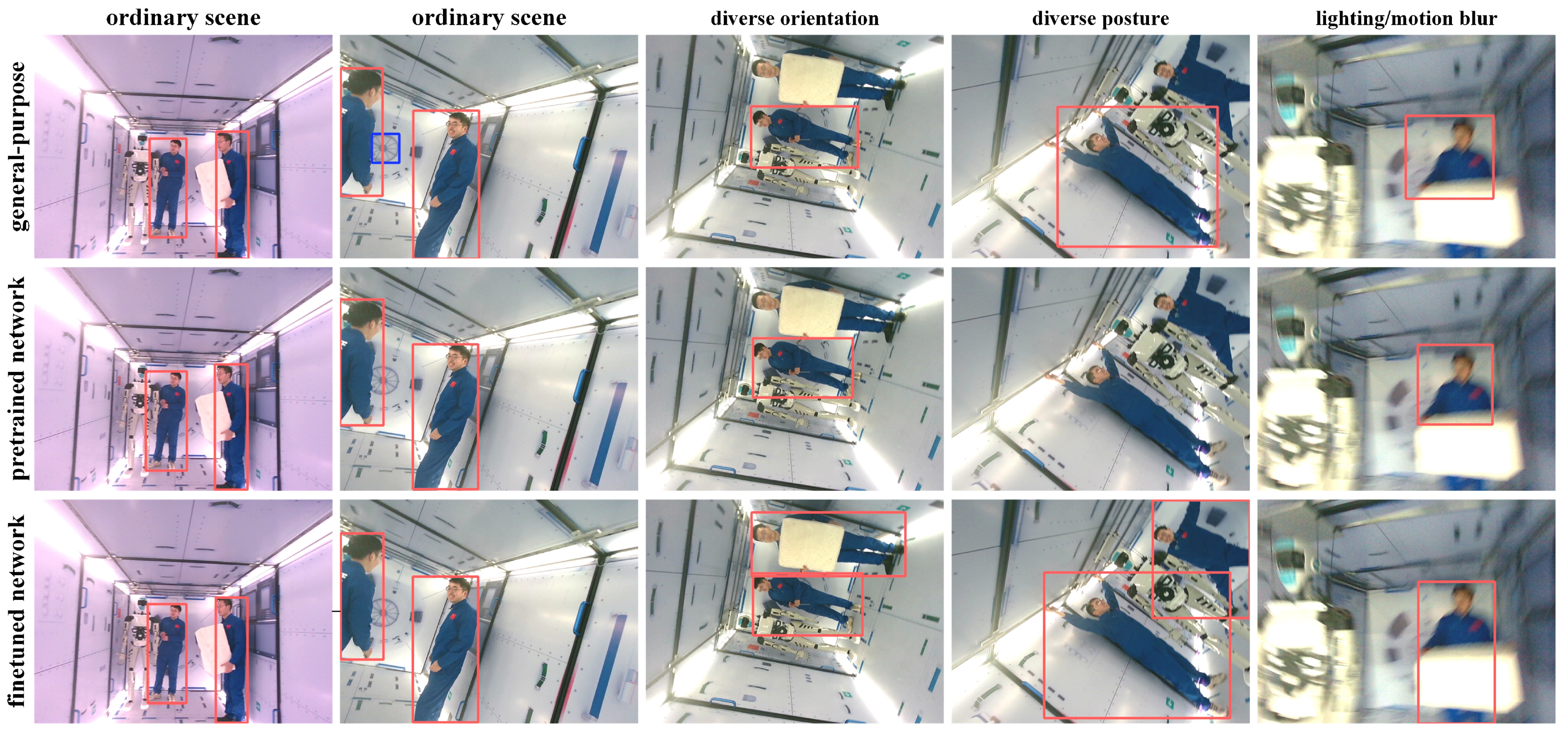
5.1. Evaluation of the Customized Astronaut Detector

The performance of the proposed astronaut-detection network is evaluated in the testing dataset (5824 images) collected in the space-station mockup. As shown in Figure 6, the fine-tuned detector shows an AP@0.5 of 99.36%, which outperforms the general-purpose detection network (85.06%) and the pretrained detector (90.78%). The superior performance of the astronaut detector benefited from the customized network structure designed for intravehicular applications and the proposed astronaut-detection dataset to mitigate possible domain inconsistency.
Figure 7 presents some typical results for comparative studies. All three networks achieved satisfactory detection when volunteers are close to the upright posture. The general-purpose network may give some false bounding boxes that do not exist in the mockup, such as a clock. When astronauts’ body postures or orientations are significantly different from daily life scenes on the ground, both the general-purpose detector and the pretrained detector degrade. A large number of missed detections and poor detections can be found. On the other hand, the fine-tuned astronaut detector still guarantees its performance when dealing with the challenging task. It is worth mentioning that all networks showed satisfactory performance to cope with illumination variation and motion blur without implementing image-enhancement algorithms [33].
The proposed astronaut detector showed superior performance to cope with the rich body postures and orientations. The estimated pixel coordinates of the bounding boxes are also more accurate than its competitors. The proposed detector runs at over 80 Hz on a GS66 laptop, proving the sufficiency for real-time performance.

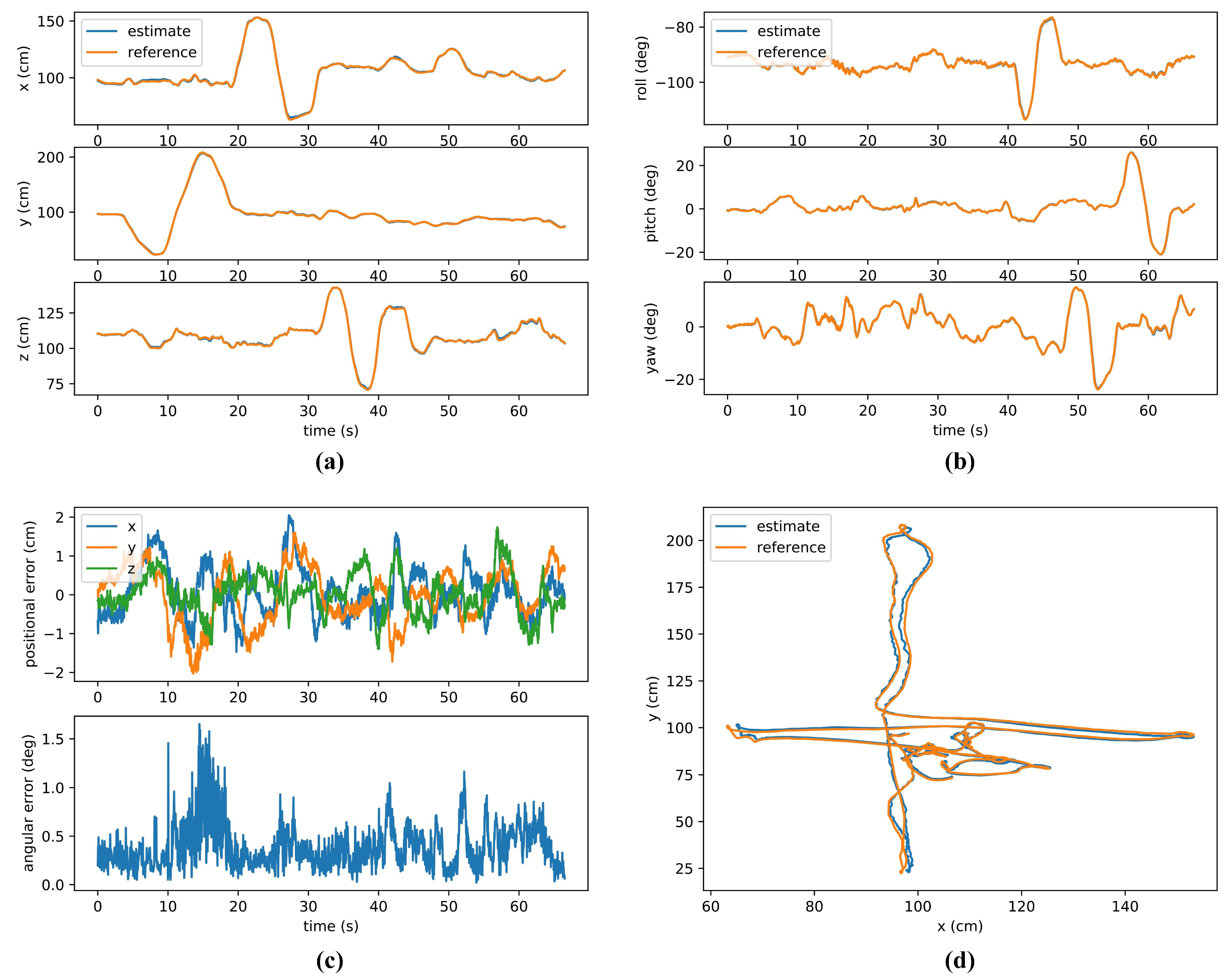
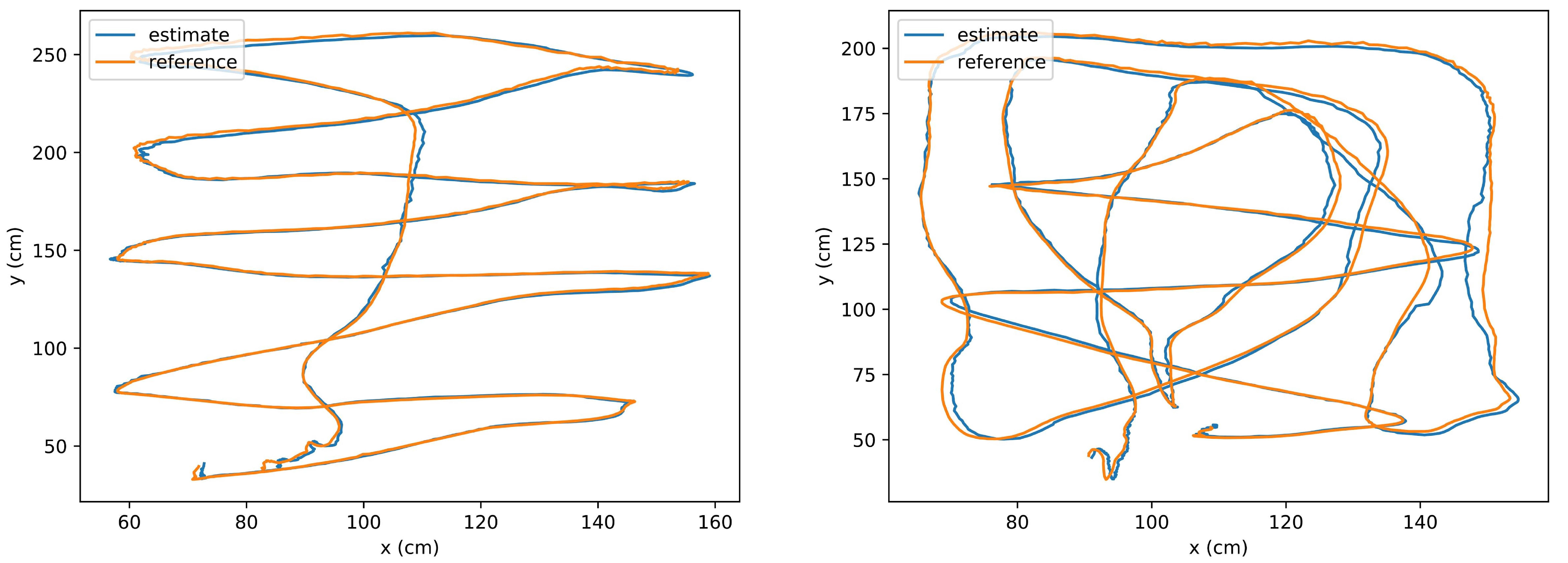
5.2. Evaluation of Map-Based Navigation in Semi-Structured and Dynamic Environments

Experiments were conducted in the mockup to test the accuracy and robustness of the proposed map-based navigation system in both static and dynamic scenarios. As shown in Figure 8a, the mockup has an internal dimension of 2 × 4 × 2 m and has high fidelity to a real space station. The handrails, buttons, experiment cabinets, and airlock provided stable visual references for visual navigation.
(A)
Performance in static environment
During the experiment, the RGB-D camera is moved and rotated constantly to collect video streams in the mockup. Four large (60 × 60 cm) Aruco markers [34] are fixed to the back of the camera to provide reference trajectories for comparison. Figure 9 presents the results in a static environment. As shown in Figure 9a,b, we performed a large range of motion in all six translational and rotational directions consecutively. The estimated 6DoF pose almost coincides with the reference trajectories. Figure 9c presents the corresponding error curves. The average positional error is less than 1cm (the maximum error does not exceed 2 cm) and the average three-axis angular error is less than 0.5°. The camera’s overall trajectory during the experiment is shown in Figure 9d. Two other random trajectories were also collected and analyzed as shown in Figure 10 where identical performance was achieved, proving the feasibility of the proposed navigation method.
(B)
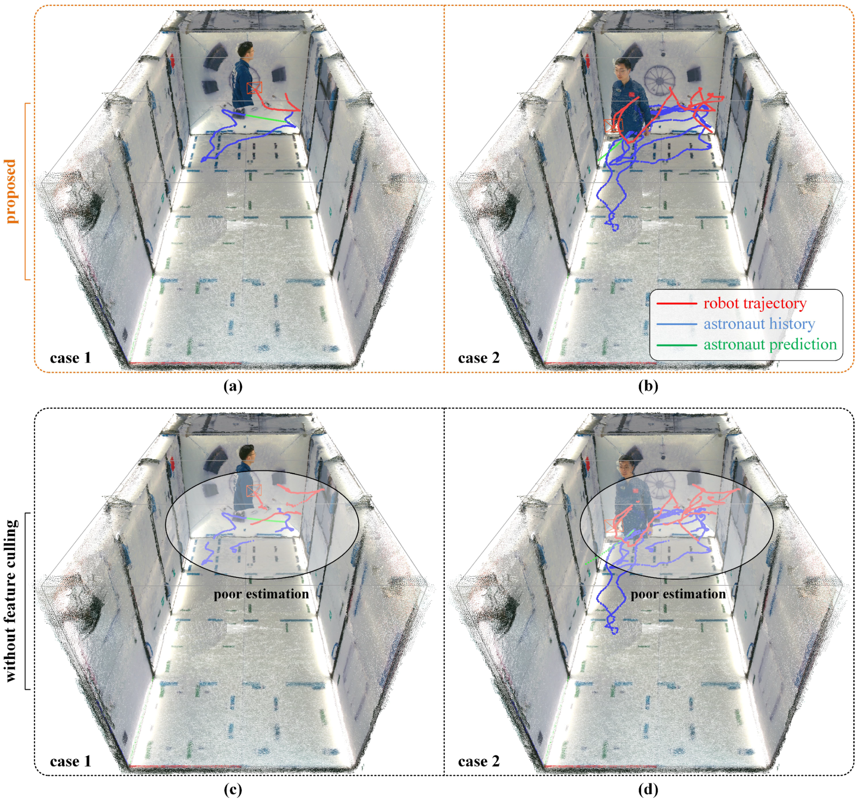
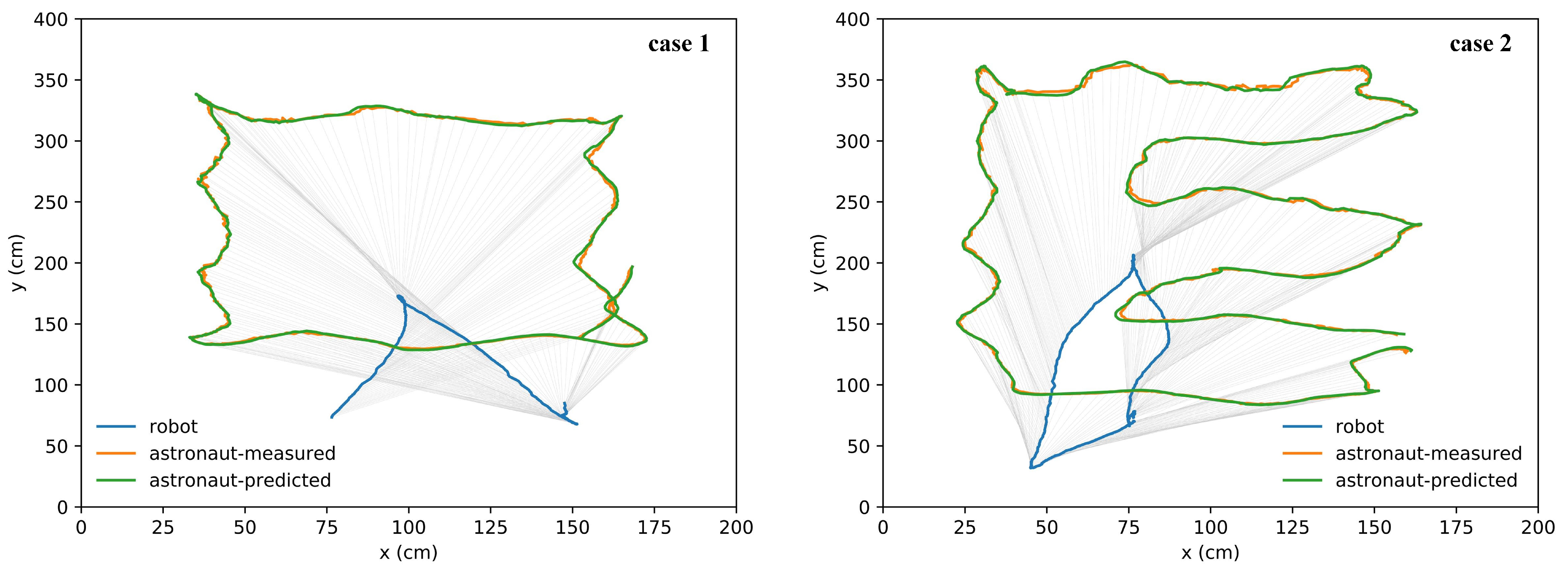
Performance in dynamic environment
Next, we evaluate the map-based navigation in dynamic scenes when the robot works along with human astronauts. As shown in Figure 8b, the humanoid robotic assistant Taikobot [35] we developed previously is used this time. The RGB-D camera mounted in the head of Taikobot is used both for astronaut detection and intravehicular navigation. During the experiment, the robot moves along with a volunteer astronaut in the mockup to provide immediate assistance. The astronaut can occasionally require a large field of vision in front of the robot during intravehicular activities. As shown in Figure 11a,b, the robot navigates robustly and smoothly in the dynamic environment with the proposed framework. Based on the stable localization result of the robot, the trajectories of the served astronaut are also estimated and predicted in the meantime, which will be discussed in Section 5.3.
By comparison, when we remove the feature-culling module in the framework, the robot becomes lost several times with the same data input as shown in Figure 11c,d. The degradation in the navigation system is caused by the dynamic feature points detected on the served astronauts, which makes it difficult for the robot to locate sufficient references for stable in-cabin navigation. As we can see, the poor localization result also led to poor trajectory estimation of the astronaut.

5.3. Verification of Simultaneous Astronaut Accompanying and Visual Navigation

Based on the robust intravehicular navigation system and the customized astronaut detector, the trajectory of the served astronaut can be identified, estimated and predicted efficiently.
Firstly, we present the results when only one astronaut is served. Figure 12 gives two typical scenarios where the robot moves along with one astronaut in the mockup. The red and green curves are the measured and predicted trajectories of the served astronaut, respectively. The blue curves are the estimated trajectories of the robot by (3). During the experiments, the astronaut was kept within the robot’s perspective. In both scenarios, the robot can navigate smoothly in the dynamic scenes, and the astronaut is tracked stably in the image flow at all times. The predicted trajectories of the astronaut are identical to the measurements. By applying the proposed motion model, the predictions are also smoothed compared with the raw measurements.
When multiple astronauts coexist, the robot is able to track a certain astronaut to provide a customized service. The task is more challenging compared with the previous examples. Figure 13 presents the results of two typical scenarios where the robot works along with two astronauts at the same time. We take case 4 to discuss in detail. As shown in the picture series in Figure 13, when the robot has confirmed (red bounding box) the target astronaut (astronaut A), the other astronaut (astronaut B) enters in the field of view of the robot. The robot can distinguish the target astronaut from astronaut B by utilizing the trajectory correlation and geometric similarity criteria (5). The robot tracks the target astronaut robustly even though the two astronauts move closely and overlap. The most challenging part occurs when astronaut B moves in between the robot and the target astronaut. When astronaut A is completely obscured from the robot, tracking loss is inevitable. However, when astronaut A reappears in the image, the robot recovers the tracking immediately. It is worth mentioning that only the trajectory and geometry criteria are used in the tracking process, which have minimal computing burden. Other criteria such as face recognition can also be incorporated into the framework for tracking recovery after long-time loss.

6. Conclusions

This paper proposed the framework of simultaneous astronaut accompanying and visual navigation in the semi-structured and dynamic intravehicular environment. In terms of the intravehicular navigation problem of IRA, the proposed map-based visual-navigation framework is able to provide real-time and accurate 6DoF localization results even in dynamic scenes during human–robot interaction. Moreover, compared with the other map-based localization methods of IRA in the literature, we achieved superior accuracy (1~2 cm, 0.5°). In terms of the astronaut visual tracking and short-term motion-prediction problem, the proposed MAP model with geometric similarity and trajectory correlation hints enables IRA to distinguish and accompany the served astronaut with minimal calculation from a moving point of view. The overall framework provided a feasible solution to address the problem of intravehicular robotic navigation and astronaut–robot coordination in the manned and constrained space station.

Author Contributions

Conceptualization, Q.Z. and Y.Z.; methodology, Q.Z. and Y.Z.; software, Q.Z.; validation, Q.Z.; formal analysis, Q.Z.; investigation, Q.Z.; resources, L.F. and Y.Z.; data curation, Q.Z. and L.F.; writing—original draft preparation, Q.Z.; writing—review and editing, L.F. and Y.Z.; visualization, Q.Z. and L.F.; supervision, L.F. and Y.Z.; project administration, L.F. and Y.Z.; funding acquisition, Y.Z. All authors have read and agreed to the published version of the manuscript.

Funding

This work is supported by Huzhou Institute of Zhejiang University under the Huzhou Distinguished Scholar Program (ZJIHI—KY0016).

Institutional Review Board Statement

Not applicable.

Informed Consent Statement

Not applicable.

Data Availability Statement

The data presented in this study are available on request from the corresponding author. The data are not publicly available due to intellectual-property protection.

Conflicts of Interest

The authors declare no conflict of interest.

Abbreviations

IRAIntravehicular robotic assistants
CIMONCrew interactive mobile companion
IFPSIntelligent formation personal satellite
SPHERESSynchronized position hold engage and reorient experimental satellite
ISSInternationall Space Station
JEMJapanese experiment module
FPNFeature pyramid network
PANPath aggregation network
IOUIntersection over union
CIOUComplete intersection over union
COCOCommon object in context
RGB-DRed green blue-depth
SFMStructure from motion
SLAMSimultaneous localization and mapping
PnPPerspective-n-point
APAverage precision
MAPMaximum a posteriori

References

  1. Sgobba, T.; Kanki, B.; Clervoy, J.F. Space Safety and Human Performance, 1st ed.; Butterworth-Heinemann: Oxford, UK, 2018; pp. 357–376. Available online: https://www.elsevier.com/books/space-safety-and-human-performance/sgobba/978-0-08-101869-9 (accessed on 10 October 2022).
  2. Russo, A.; Lax, G. Using artificial intelligence for space challenges: A survey. Appl. Sci. 2022, 12, 5106. [Google Scholar] [CrossRef]
  3. Miller, M.J.; McGuire, K.M.; Feigh, K.M. Information flow model of human extravehicular activity operations. In Proceedings of the 2015 IEEE Aerospace Conference, Big Sky, MT, USA, 7–14 March 2015. [Google Scholar]
  4. Miller, M.J. Decision support system development for human extravehicular activity. Ph.D. Thesis, Georgia Institute of Technology, Atlanta, GA, USA, 2017. [Google Scholar]
  5. Akbulut, M.; Ertas, A.H. Establishing reduced thermal mathematical model (RTMM) for a space equipment: An integrative review. Aircr. Eng. Aerosp. Technol. 2022, 94, 1009–1018. [Google Scholar] [CrossRef]
  6. Li, D.; Zhong, L.; Zhu, W.; Xu, Z.; Tang, Q.; Zhan, W. A survey of space robotic technologies for on-Orbit assembly. Space Sci. Technol. 2022, 2022, 9849170. [Google Scholar] [CrossRef]
  7. Smith, T.; Barlow, J.; Bualat, M. Astrobee: A new platform for free-flying robotics on the international space station. In Proceedings of the 13th International Symposium on Artificial Intelligence, Robotics, and Automation in Space, Beijing, China, 20–22 June 2016. [Google Scholar]
  8. Mitani, S.; Goto, M.; Konomura, R. Int-ball: Crew-supportive autonomous mobile camera robot on ISS/JEM. In Proceedings of the 2019 IEEE Aerospace Conference, Yellowstone Conference Center, Big Sky, MT, USA, 2–9 March 2019. [Google Scholar]
  9. Experiment CIMON—Astronaut Assistance System. Available online: https://www.dlr.de/content/en/articles/missions-projects/horizons/experimente-horizons-cimon.html (accessed on 10 October 2022).
  10. Zhang, R.; Wang, Z.K.; Zhang, Y.L. A person-following nanosatellite for in-cabin astronaut assistance: System design and deep-learning-based astronaut visual tracking implementation. Acta Astronaut. 2019, 162, 121–134. [Google Scholar] [CrossRef]
  11. Liu, Y.Q.; Li, L.; Ceccarelli, M.; Li, H.; Huang, Q.; Wang, X. Design and testing of BIT flying robot. In Proceedings of the 23rd CISM IFToMM Symposium, Online, 20–24 September 2020; Available online: http://doi.org/10.1007/978-3-030-58380-4_9 (accessed on 10 October 2022).
  12. NASA Facts Robonaut 2, Technical Report. Available online: https://www.nasa.gov/sites/default/files/files/Robonaut2_508.pdf (accessed on 10 October 2022).
  13. Meet Skybot F-850, the Humanoid Robot Russia Is Launching into Space. Available online: https://www.space.com/russia-launching-humanoid-robot-into-space.html (accessed on 10 October 2022).
  14. Chen, L.; Lin, S.; Lu, X.; Cao, D.; Wu, H.; Guo, C.; Liu, C.; Wang, F. Deep neural network based vehicle and pedestrian detection for autonomous driving: A survey. IEEE Trans. Intell. Transp. Syst. 2021, 22, 3234–3246. [Google Scholar] [CrossRef]
  15. Bochkovskiy, A.; Wang, C.Y.; Liao, H. YOLOv4: Optimal speed and accuracy of object detection. arXiv 2020, arXiv:2004.10934. [Google Scholar]
  16. Avdelidis, N.P.; Tsourdos, A.; Lafiosca, P.; Plaster, R.; Plaster, A.; Droznika, M. Defects recognition algorithm development from visual UAV inspections. Sensors 2022, 22, 4682. [Google Scholar] [CrossRef] [PubMed]
  17. Zhang, R.; Wang, Z.K.; Zhang, Y.L. Astronaut visual tracking of flying assistant robot in space station based on deep learning and probabilistic model. Int. J. Aerosp. Eng. 2018, 2018, 6357185. [Google Scholar] [CrossRef]
  18. Zhang, R.; Zhang, Y.L.; Zhang, X.Y. Tracking in-cabin astronauts Using deep learning and head motion clues. Int. J. Aerosp. Eng. 2018, 9, 2680–2693. [Google Scholar] [CrossRef]
  19. Saenz-Otero, A.; Miller, D.W. Initial SPHERES operations aboard the International Space Station. In Proceedings of the 6th IAA Symposium on Small Satellites for Earth Observation, Berlin, Germany, 23–26 April 2008. [Google Scholar]
  20. Prochniewicz, D.; Grzymala, M. Analysis of the impact of multipath on Galileo system measurements. Remote Sens. 2021, 13, 2295. [Google Scholar] [CrossRef]
  21. Coltin, B.; Fusco, J.; Moratto, Z.; Alexandrov, O.; Nakamura, R. Localization from visual landmarks on a free-flying robot. In Proceedings of the 2016 IEEE/RSJ International Conference on Intelligent Robots and Systems, Seoul, Republic of Korea, 8–9 October 2016. [Google Scholar]
  22. Kim, P.; Coltin, B.; Alexandrov, O. Robust visual localization in changing lighting conditions. In Proceedings of the 2017 IEEE International Conference on Robotics and Automation, Marina Bay Sands, Singapore, 29 May–3 June 2017. [Google Scholar]
  23. Xiao, Z.; Wang, K.; Wan, Q.; Tan, X.; Xu, C.; Xia, F. A2S-Det: Efficiency anchor matching in aerial image oriented object detection. Remote Sens. 2021, 13, 73. [Google Scholar] [CrossRef]
  24. He, K.; Zhang, X.; Ren, S.; Sun, J. Deep residual learning for image recognition, In Proceedings of the 2016 IEEE Conference on Computer Vision and Pattern Recognition, Las Vegas, NV, USA, 26 June–1 July 2016.
  25. Liu, S.; Qi, L.; Qin, H.; Shi, J.; Jia, J. Path aggregation network for instance segmentation. In Proceedings of the 2018 IEEE Conference on Computer Vision and Pattern Recognition, Salt Lake City, UT, USA, 19–21 June 2018. [Google Scholar]
  26. COCO Common Objects in Context. Available online: https://cocodataset.org/ (accessed on 10 October 2022).
  27. Shao, S.; Zhao, Z.; Li, B.; Xiao, T.; Yu, G.; Zhang, X.; Sun, J. CrowdHuman: A benchmark for detecting human in a crowd. arXiv 2018, arXiv:1805.00123. [Google Scholar]
  28. Zheng, Z.; Wang, P.; Ren, D.; Liu, W.; Ye, R.; Hu, Q.; Zuo, W. Enhancing geometric factors in model learning and inference for object detection and instance segmentation. IEEE Trans. Cybern. 2020, 52, 8574–8586. [Google Scholar] [CrossRef] [PubMed]
  29. Jiang, S.; Jiang, C.; Jiang, W. Efficient structure from motion for large-scale UAV images: A review and a comparison of SfM tools. ISPRS J. Photogramm. Remote. Sens. 2020, 167, 230–251. [Google Scholar] [CrossRef]
  30. Mur-Artal, R.; Tardos, J.D. ORB-SLAM2: An open-source SLAM system for monocular, stereo and RGB-D cameras. IEEE Trans. Robot. 2017, 33, 1255–1262. [Google Scholar] [CrossRef] [Green Version]
  31. Koletsis, E.; Cartwright, W.; Chrisman, N. Identifying approaches to usability evaluation. In Proceedings of the 2014 Geospatial Science Research Symposium, Melbourne, Australia, 2–3 December 2014. [Google Scholar]
  32. Hornung, A.; Wurm, K.M.; Bennewitz, M.; Stachniss, C.; Burgard, W. OctoMap: An efficient probabilistic 3D mapping framework based on octrees. Auton. Robot. 2013, 34, 189–206. [Google Scholar] [CrossRef] [Green Version]
  33. Irmak, E.; Ertas, A.H. A review of robust image enhancement algorithms and their applications. In Proceedings of the 2016 IEEE Smart Energy Grid Engineering Conference, Oshawa, ON, Canada, 21–24 August 2016. [Google Scholar]
  34. Romero-Ramirez, F.J.; Muñoz-Salinas, R.; Medina-Carnicer, R. Speeded up detection of squared fiducial markers. Image Vis. Comput. 2018, 76, 38–47. [Google Scholar] [CrossRef]
  35. Zhang, Q.; Zhao, C.; Fan, F.; Zhang, Y. Taikobot: A full-size and free-flying humanoid robot for intravehicular astronaut assistance and spacecraft housekeeping. Machines 2022, 10, 933. [Google Scholar] [CrossRef]
Figure 1. Architecture of the lightweight and customized astronaut-detection network. Layers in blue are the feature-extraction modules. Layers in the dashed box are characterized by abundant cross-layer connections for feature fusion. Layers in green are the two anchor-based detection heads.
Drones 06 00397 g001
Figure 2. A set of correction parameters is estimated with respect to the most similar reference boxes to characterize the final detection.
Drones 06 00397 g002
Figure 3. Examples in the customized astronaut-detection dataset.
Drones 06 00397 g003
Figure 4. Various maps constructed and registered to the space-station mockup. (a) The (sparse) point-cloud map. (b) The dense point-cloud map. (c) Octomap for obstacle avoidance and motion planning.
Drones 06 00397 g004
Figure 5. Computational work flow of the integrated framework of simultaneously astronaut accompanying and visual navigation in the semi-structured and dynamic intravehicular environment.
Drones 06 00397 g005
Figure 6. Comparison of the precision-recall curves of three detectors in the task of astronaut detection in the space-station mockup.
Drones 06 00397 g006
Figure 7. Astronaut-detection performance of the general-purpose network, pretrained network and the fine-tuned astronaut detector on the testing dataset.
Drones 06 00397 g007
Figure 8. The ground experimental environment. (a) The space-station mockup of high fidelity. (b) The humanoid robotic assistant Taikobot used in the experiment.
Drones 06 00397 g008
Figure 9. Localization and orientation performance of the proposed map-based navigation system in static environment. (a) Position curves in world frame. (b) Euler angle curves with respect to the world frame. (c) Positional error and three-axis angular error. (d) The estimated trajectories in the XY plane of the space-station mockup.
Drones 06 00397 g009
Figure 10. Two random trajectories tested in the space-station mockup (static environment).
Drones 06 00397 g010
Figure 11. Localization performance of the map-based navigation system in dynamic environment. Red lines are the estimated trajectories of the robotic assistant. Blue and green lines are the estimated and predicted trajectories of the served astronaut, respectively. (a,b) performance of the proposed framework. (c,d) performance without feature culling.
Drones 06 00397 g011
Figure 12. Experimental results of simultaneous astronaut tracking and visual navigation when the robotic assistant accompanies one astronaut.
Drones 06 00397 g012
Figure 13. Experimental results of simultaneous astronaut tracking and visual navigation when multiple astronauts coexist in the space-station mockup. The red bounding boxes in the sequentially numbered pictures denote the target astronaut. The dotted curves in the two sketches denote the routes of astronaut B.
Drones 06 00397 g013
Table 1. Comparison between our proposed approach and existing methods in the literature.
Robotic AssistantNavigation MethodAccuracyAdditional DevicesDynamic SceneDrawbacks
SPHERES [19]radio-based0.5 cm/2.5°ultrasonic beaconsyeslimited workspace
Astrobee [7]map-based5~12 cm/1°~6°not requirednofor static scene
Int-Ball [8]marker-based2 cm/3°markeryeslimited field of view
CIMON [9]vision-based////
IFPS [10]map-based1~2 cm/0.5°not requirednofor static scene
Robonaut2 [12]/////
Skybot F-850 [13]/////
Proposedmap-based1~2 cm/0.5°not requiredyes/
Table 2. Detection-head specifications of the lightweight and customized astronaut detector.
Detection HeadGrid SystemPrior Bounding BoxesRatioPredictions for Each Anchor
140 × 40[100, 200]1/2 Δ x , Δ y , σ w , σ h , p i ×3
[200, 100]2/1
[150, 150]1/1
220 × 20[200, 400]1/2 Δ x , Δ y , σ w , σ h , p i ×3
[400, 200]2/1
[300, 300]1/1
Publisher’s Note: MDPI stays neutral with regard to jurisdictional claims in published maps and institutional affiliations.

