
High Performance Convertible Coleopter Drones


Aerospace Engineering Department, University of Kansas, Lawrence, KS 66045, USA
Drones 2022, 6(11), 346; https://doi.org/10.3390/drones6110346
Submission received: 19 August 2022
/
Revised: 31 October 2022
/
Accepted: 3 November 2022
/
Published: 8 November 2022
(This article belongs to the Special Issue Conceptual Design, Modeling, and Control Strategies of Drones-II)
Abstract
:This paper opens with an historical overview of efforts to develop micro-, mini-, and organic aerial vehicles (MAVs and OAVs) in the 1990’s. Although conceived during WWII, coleopters would not see serial production for 60 years. The paper continues with programmatic aspects of hovering coleopter development of the 1990’s and describes the technical motivations behind in-flight conversion from hover-mode to missile-mode flight and the record-setting XQ-138 family of convertible coleopters. As the first commercially successful family of such aircraft, the XQ-138 was taken from initial concept through configuration design, detailed design, patenting, prototyping, proof-of-concept, production, flight testing, qualification, and eventually high rate production, all with private funding. The paper lists basic engineering drivers, covers fundamental sizing methods, presents weight fraction data, and describes flight test procedures, locations, conditions, and results. High-speed flight test data show the stock aircraft achieving speeds in excess of 164 mph (263 kph) with endurances in excess of an hour at that speed with a special dash-optimized version reaching 288 mph (463 kph) for a few minutes. Videos from flight testing and live-fire exercises are shown at Redstone Arsenal, Eglin Air Force Base, and Fort Benning test ranges under extreme conditions. The paper concludes with an assessment of civil and military variants for a variety of military missions and commercial uses.
1. Introduction
In the 1980s and early 1990s, US drug-enforcement agencies were facing an ever-growing problem: more and more deadly tunnels on the southern border. While smugglers’ tunnels were nothing new, agents were encountering large numbers of booby traps and increasingly dangerous explosive devices, some of which had cost the lives of agents and working animals. In response, the US Department of Defense (DoD) Counterdrug Technology Office (CDTO) requested proposals for a small aircraft with no dimension greater than 6″ (15 cm) that could proceed down into subterranean tunnels, video the surroundings in low or no light, move up to 20 m underground in any direction, and hover for as long as a day. The winning proposal was submitted by Dr. Gary Lee of Lutronix Corporation, Del Mar, California. Therefore, in 1994 the DoD issued a contract for what would lead to its first Micro Aerial Vehicle (MAV).
1.1. The US Department of Defense’s First Micro Aerial Vehicle (MAV)
At the same time, pioneering work on high-speed micro-flight-control actuators and subscale aircraft was underway. The world’s first fixed-wing aircraft using all adaptive materials for flight control had just been flown in the Adaptive Aerostructures Laboratory (AAL) of Auburn University, and would soon be followed by the first adaptive rotary-wing aircraft [1,2]. At Lutronix, multiple attempts at achieving even staggering vertical flight with a micro camera assembly had all failed and a new technological approach was needed. Reference [3] introduced Lutronix to adaptive aerostructures. The result would be some of the world’s fastest and lightest flight control actuators. At only 380 mg, with a corner frequency over 42 Hz, the Flexspar family of flight control actuators would become a critical enabling technology behind the Kolibri, the DoD’s first MAV. One particularly outstanding characteristic of the Flexspar actuators was that they operated at nearly 100 V with currents typically under 5 mA. Special electrical motors were wound to operate at several hundred Volts. This meant that the electrical tether weight and volume would be greatly reduced to just a few mg/m and it would become so flexible and supple that trailing it behind the aircraft would be no trouble. Figure 1 shows three of the most important enabling components of the Kolibri: (i) a Tokin 16DIO piezoelectric gyro, (ii) CMOS mini-camera, (iii) piezoelectric Flexspar micro-stabilator, and the integration of these components into the Lutronix Kolibri.
The performance of the Kolibri exceeded all specifications and resulted in a number of flight demonstrations for sponsors. By today’s standards, flight of an aeromechanically stable 6″ (15 cm) tethered aircraft with a blurry 240 × 320 B/W camera would be a non-event, but 25 years ago, it was a first. Figure 2 is a good reminder of just how primitive things were at the time and shows the Kolibri (i) on the ground during a preflight check, (ii) airborne at a loading dock with bystander, (iii) hovering and translating with a trailing tether, and (iv) the view from the on-board camera.
Following the successes of the Lutronix Kolibri program, DARPA TTO engaged Lutronix for the next, natural evolutionary stage of aircraft development: freeflight. In 1998, DARPA TTO Program Manager Jim McMichaels laid out a mission profile that included a vertical takeoff and flight carrying a color micro video camera at 240 × 320, transmitter, operable in winds up to 18 kts, rain through 1″/h (2.5 cm/h), and 15 min. endurance. Lutronix evolved three aircraft to meet the specification: The LuMAV1, 2, and 3. The last iteration of the aircraft used a 141 W (0.19 hp) Norvel 0.061 powerplant and grid fins for pitch and roll control and active turning vane flaps for yaw control. The aircraft was made from a single ply of graphite-epoxy composite prepreg cloth cured at 350 °F (177 °C). The high-temperature cure was to accommodate powerplant exhaust within a muffler bay which wrapped around the powerplant. The rotor guard housed the electronics and power supply so as to pull the center of gravity as high as possible. The high c.g. position increased the tail volume coefficient and therefore control authority. The aircraft total gross weight was 15.5 oz (441 g).
The September 2000 DARPA TTO MAV fly-off in Quantico, Virginia featured a handful of flightworthy aircraft and several dozen displays from component suppliers and related technology companies. AeroVironment’s Black Widow was the top-performing fixed-wing aircraft, not only meeting the 6″ (15 cm) size requirements, but also completed multiple racetrack patterns. The Lockheed Skunkworks aircraft was twice that size and caught fire. The only successful VTOL MAV was the Lutronix LuMAV3, which flew with full 240 × 320 video feed displayed live. Pilot Ken Fidler flew against 8–12 kt farfield gusts for an audience of dignitaries and military leaders as shown below in Figure 3, which shows (i) undergraduate research assistant Stacey Lamb performing preflight tests, (ii) the LuMAV3A in hovering flight at 9 m altitude, (iii) flight demonstration at Quantico, Virginia for a DARPA fly-off, September 2000.
1.2. DARPA Organic Aerial Vehicle (OAV) Competition and Problems with Basic Physics
Following the successes of the LuMAV program, DARPA TTO solicited larger aircraft to be developed as Organic Aerial Vehicles (OAV) on the Future Combat System (FCS), which was under development for the US Army at the time. The OAV specification called for greater hover endurance, greater payloads, higher resistance to gusts, and most importantly a large increase in range and dash speeds. To answer the RFP, a new company was formed around Lutronix personnel: Micro Autonomous Systems (MASS). As it was also headed up by Dr. Gary Lee, MASS was well positioned to take on the new OAV RFP, but with a more robust approach.
With geometric constraints loosened to allow for aircraft up to 12″ (30.5 cm) in diameter and 3 ft. (91 cm) long, much more robust designs were considered. Given the geometric constraints and desired performance, a coleopter was a natural choice. Open-rotor aircraft were simply non-viable as the specification included a “wall-strike” condition, wherein the aircraft had to be able to hit a wall with 15 g’s of acceleration and stay airborne. Only the rotor shielding aspects of a rotor guard could suitably satisfy this condition. Other characteristics included noise limitations. By shielding the powerplant and rotor by a properly designed rotor guard with internal noise-mitigating features, the noise specification could be met. The history of previous coleopter programs, designs, and physics played a big role in laying out the MASS aircraft. The SNECMA Coléoptère and the Hiller VZ-1 families were two leading families as both made it to flight test, and both were beset with successes and failures. Figure 4 shows both families of coleopters including (i) the VZ-1 in hovering flight, (ii) the US Patent covering the VZ-1 patent, and (iii) the SNECMA Coléoptère being erected for flight.
The biggest problem faced by early coleopters was discovered in the flight test of the aforementioned aircraft and presented in the proposal submitted by MASS to DARPA TTO wherein it was explained in great detail. In short, there is a form of debilitating instability that tends to pitch coleopters aftward as the aircraft moves faster and faster in forward flight. To maintain reasonable hover efficiency, the upper lip of a coleopter must be gently curved. Ideally, the lip will take the shape of a quasi-isentropic inlet such as those used for jet engine testing. If the aircraft is designed to convert or fit within geometric constraints, then the radius of the lip shrinks.
Aircraft such as the VZ-1 and Coléoptère were short coupled (i.e., possessed a comparatively short distance between the c.g. and aerodynamic center of the lower aerodynamic effectors) with large lip radii. As a result, forward flight speeds were extremely limited. Nonetheless, broad lips such as those of both the Coléoptère and the VZ-1 were in the order of 10% duct diameter. It is this very feature that allows it to hover with nontrivial hover power reductions, but at a price. The more quickly the aircraft translates through the air in hover mode, the faster the air moves over the upwind lip of the rotor guard, and slower over the downwind lip. This generates strong suction over the upwind lip and weak suction over the downwind lip, in turn producing ever-increasing pitchback instability with increasing airspeed. This pitchback instability is extremely hard to correct for if the aircraft is short coupled as the control power is limited. Figure 5 shows the compounding problem that the aft control effectors must apply forces in the direction of disturbance. This exacerbates the stationkeeping error, which in turn makes it harder if not nearly impossible to both hold aircraft attitude and spatial position in gust fields.
Figure 5 shows sequence of events that occurs in a short-coupled coleopter-type aircraft when exposed to a strong lateral gust: (i) the aircraft is exposed to a gust field which hits the airframe from the side, (ii) a large lateral drag force is generated by the crossflow component of flow. This crossflow forces the aircraft downstream. More debilitating is that the upstream lip forms a strong suction peak while the downstream rotor guard lip encounters an increase in static pressure. This combination of lip suction differential between upwind and downwind lips generates a pitchback moment, which sends the aircraft downwind further. (iii) The flight control system applies corrective moments which force the aircraft to translate further downwind. (iv) In some circumstances, the control forces are so great that the aircraft pitch attitude can be tilted to allow the thrust vector to drag the aircraft upstream, at which time the aircraft eventually flies against the wind. System-level lag often induces the aircraft to experience excessive lateral deviations and has been shown in many flight tests; such corrections can easily induce crashes. In short, Figure 5 shows that stationkeeping with a short-coupled coleopter configuration is a serious challenge due to the inherent pitchback instability and challenges control effector configuration.
If one were to estimate the position of the lateral aerodynamic center in hover mode, it is typically from 8 to 28‰ above the rotor guard lip on many aircraft configurations such as the VZ-1 and Coléoptère depending on lip radius. This means that to achieve aeromechanical stability in hover, the center of gravity must be above that point. Making problems of inherent aeromechanical stability hover worse is the presence of a central upper fuselage. As crosswinds hit the fuselage, they often separate on the leeward side of the fuselage, generating a low dynamic pressure “burble” of air. This low energy, unsteady inflow, is in turn ingested on the downwind side of the rotor which decreases thrust generation from that quadrant. The flow on the upwind side of the fuselage experiences just the opposite flow dynamic which increases thrust on the upwind quadrant of the rotor, thereby increasing pitchback instabilities substantially. In aircraft design parlance, the lateral aerodynamic center in hover-mode flight is effectively boosted as high as 75‰ above the rotor guard lip, independent of lip diameter. With an aerodynamic center this high, stable flight in gust fields while station keeping is often simply impossible.
Although the MASS design team worked hard to warn DARPA reviewers of the basic physics presented by popular coleopter configurations being presented, they funded the development of aircraft with precisely these problems. The result was predictable: in September of 2003 during a flight demonstration at Ft. Eustis, Virginia, the iSTAR was hit by light crosswinds and entered a catastrophic dive in front of a crowd of assembled military commanders, dignitaries, and press. The engineering team explained: “We didn’t have the control authority needed for the prevailing conditions”. “Unfortunately, this effect limited the forward speed to a mere 26 kph (16 mph) and caused erratic handling in windy conditions” [8]. Sadly, neither the funding agency, nor the DoD, nor the wider technical community fully absorbed the lessons presented so publicly as this configuration was (and still is) regularly funded and pursued from time to time. Many short-coupled ducted fan designs such as the one described above have been studied with special attention paid to pitchback instability because it is the primary “show-stopper” for this class of aircraft [9]. Other works examine static aerodynamics of short-coupled coleopter designs independent of fully free-body aeromechanical modes [10,11]. This is understandable as the demonstrated dangers of conversion testing (described above) often lead to complete hull loss given the problems with pitchback instabilities. Several studies examined issues around ducted fans from purely computational standpoints. No doubt because of tremendous computational cost, studies such as this are typically carried out independently of aeromechanical considerations, concentrating instead on aerodynamic issues [12]. Still other works looked more broadly at the aerodynamics of ducted fans when coupled to lifting surfaces and when ganged together in configurations using a multitude of ducted fans [13]. Other authors are clearly aware of the pitchback instability issues as they lay out the entire coleopter design, even going so far as to place a center of pressure above the entire aircraft when in a hover state (representing pitchback instability) [14]. Some important attempts were made to include aeromechanics analysis by coupling CFD solutions to control loops through gust fields and transition [15,16]. Some authors have worked on optimization of short-coupled electric ducted fan UAVs considering only the steady-state, static case without aeromechanical considerations [17]. More hybrid approaches to estimating short-coupled ducted fan UAV operations in hovering flight were carried out using numerical methods [18]. Another excellent approach to the problem of aeromechanical issues is to increase the control authority of short-coupled ducted fan aircraft is by boosting the flow turning levels at the duct exit while employing ever-more sophisticated controllers, as seen in Ref. [19].
1.3. Hover, Conversion and Dash Stability—A Workable Coleopter Configuration from 1944
Whenever a technologist wishes to explore “new” and/or “innovative” aerospace configurations, it is always wise to look back to German wartime concepts. More often than not, it will be discovered that what is considered “novel” today was actually conceived (and often reduced to practice) between 1933 and 1945. Such is the case with coleopters. As WWII raged on, German civil infrastructure, especially runways were being obliterated by Allied bombing raids. Desperate for a counter, the Luftwaffe solicited designs for aircraft that could dash as fast as allied fighters and yet require no runway. This of course meant that such aircraft could be based anywhere and deployed from otherwise innocuous-looking buildings, then take off vertically [20].
In response, the Heinkel Wespe (Wasp) in 1944 and later the Lerche (Lark) were designed as point interceptors to defend critical infrastructure. Conceived and evolved by Heinkel designers Dr. Ing. Kurt Reiniger and Dr. Ing. Gerhard Schulz, the aircraft were well ahead of their time in terms of configuration, but could not be realized during the war because various subsystems were not yet mature. Still, the Heinkel designs (Figure 6, below) would prove invaluable in advising the configurations of later coleopters [21].
The primary technologies that would have enabled the Wespe and Lerche are related to stability and control. The first problem they would have experienced is the lack of a workable stability, control, and auto-land system. As was discovered in the Convair XFY-1 Pogo program, human factors, substandard instrumentation, and no automation made tailsitter VTOL operations dangerous and led to multiple incidents and accidents [22,23,24]. The Wespe and Lerche would have suffered from the same dynamics. The second big issue is the high level of control coupling and related lack of control effector orthogonality. Pitch, roll, and yaw are highly coupled in every flight mode: takeoff, conversion, dash. Such coupling would have unnecessarily complicated flight control computers, which were not available in the 1940s. Other than those two major issues, the design would have been fundamentally workable. The mission profile envisioned by the Heinkel designers was highly innovative for the day, as seen in Figure 7.
While the mission profile above was highly advanced for 1944, the physics associated with the landing conversion could only be determined by actual flight testing (as was shown in the XQ-138 program). Even the best wind tunnel testing and CFD codes of today would have an exceedingly difficult time capturing the highly coupled, separated flow, rotor–airframe–empennage interactions. What was done right in the Lerche and Wespe designs (given the benefit of nearly 80 years of hindsight) was almost everything else. Unlike the iSTAR, the Heinkel designers understood full well the importance of proper aerodynamic center placement and inherent aeromechanical stability in hover, transition, and high-speed flight. Their positioning of the empennage indicates that a nontrivial amount of wind tunnel testing was done, as the XQ-138 (to be discussed later) wound up with almost precisely the same location and tail volume coefficient after hundreds of hours of flight test and dozens of design changes so as to optimize the empennage position on experimental flight test aircraft in the field.
The second feature that was also clearly an artifact of painstaking wind tunnel and hover stand testing was the rotor guard aspect ratio. When such rotor guards are optimized only for one condition such as hover, their aspect ratios frequently decrease to 1 or lower. Because the Wespe and Lerche were designed to intercept Allied bombers and fighters, a low aspect ratio rotor guard would have unnecessarily introduced large increments in wetted area. This in turn would drive parasite drag. Minimizing the rotor guard wetted area would have been important for maintenance of high dash speeds. An outstanding compromise allowing for very good hover performance, a suitably large cross-sectional area to support transition, and a minimal wetted area for dash would have been an aspect ratio between 3 and 4 as was shown during the execution and painstaking optimization of the XQ-138. The Wespe and Lerche aspect ratios were 3.6–4 (depending on variant). Clearly, the Heinkel engineers knew what they were doing.
Figure 7 highlights the dramatic differences between convertible coleopters and fixed- and rotary-wing drones. Rotary-wing drones are typically optimized to achieve efficient hover performance and stationkeeping in a gusty environment without real consideration of high dash speeds. Fixed-wing drones are typically optimized to achieve good loiter times in reasonable atmospheric conditions for minimal power at relatively low speeds. The convertible coleopters on the other hand have two primary optimization points: efficient hover and efficient high-speed dash in one aircraft. Figure 7 shows Heinkel’s scheme to address both hover and dash requirements via conversion.
2. A Utilitarian Coleopter Configuration: The XQ-138
The XQ-138 is the product of years of study of historical aerospace configurations, their successes (and failings), and very specific customer needs. In this case, the US Federal Government had a need for “Organic Aerial Vehicles” (OAVs) to operate from their new Future Combat System, take off and land vertically, and travel several tens of miles at high speeds under a wide range of atmospheric conditions.
2.1. XQ-138 Design Drivers and Overall Configuration
With the lessons learned from the Heinkel, Hiller, Piasecki, SNECMA, and Convair aircraft and many others, MASS engineers embarked on the design of a convertible coleopter that could operate in real atmospheric conditions—wind, dust, rain, snow etc. Although DARPA chose the iSTAR configuration for the OAV, MASS was part of the Boeing team and as such was introduced to Singapore Technologies Aerospace. ST Aero. Managers saw promise in the configuration and funded its development. The first step in the development of the new aircraft was to solidify the mission profile, as shown below in Figure 8.
The reader will note that the speeds are comparatively high with respect to typical subscale UAVs of today while the specified range is low for aircraft that fly like airplanes. Clearly, the mission profile above satisfied both FCS needs (which are tactical, not strategic) and was compatible with the Singaporean defense posture [25,26,27]. Of course, different mission profiles can be generated and will simply result in a differently shaped and sized aircraft. As was the case of the mission profile shown in Figure 7, a basic mistake (or misleading maneuver) in the XQ-138 Mission Profile is that the dash-to-descent/land conversion is incorrect. At the onset of the project, it simply was not known that such an instantaneous maneuver with a coleopter was not possible. That maneuver takes time and must be done carefully so as not to induce a catastrophic divergence as will be shown in the following section. The mission specification called for flight in up to 12″/h (30 cm/h) in rain (monsoon rains) as well as a 15 g wall strike tolerance as well as resistance to a combat shotgun at 15 m and autonomous GPS guidance. The profile above resulted in the aircraft shown in Ref. [28] and Figure 9 below:
The XQ-138 was a direct predecessor and functional prototype of the successful coleopter the ST Aerospace Fantail family of UAVs [29].
Although the outstanding work of Dr. Ing. Kurt Reiniger and Dr. Ing. Gerhard Schulz that took place 57 years earlier clearly advised the design, one major deviation is noteworthy: the empennage. Two factors influenced the selection and configuration of the empennage: First, a fuselage length constraint of 28″ (71 cm) meant that the aircraft would be a bit stubbier than it would have been naturally so as to fit within a launch tube of limited length. The second one is the use of grid (or “lattice”) fins. Although the Soviets are generally given credit for implementing grid grid fins on fielded weapon systems, as they were (and are) used on the N-1 rocket and SS-10 ICBM to name a few, real credit should be shared a few years back [30,31,32]. The concept of box fins dates to before WWI with the work of aviators such as Voisin [33]. It was discovered that end-plated empennages maximized normal force gradients for a given design space and made them highly resistant to high angle of attack stall. Many munitions employed as early as WWI used ribbed ring-tails which did precisely this [34,35], The empennages evolved further during WWII to those found on weapons such as the Fritz-X [36].
Clearly, enclosed empennages with internal members providing structural support and/or control were and are nothing new. Indeed, they are even found today on fielded air-to-air missiles, air-to-ground gravity weapons, and satellite-launching rockets [37,38,39]. Given that grid fins are used in aerospace systems that are length constrained (such as submarine-launched ICBMs) as they allow for greater static margins, such a choice is natural for the XQ-138. The grid fins were also arranged so as to decouple the controls. Figure 10, below, shows two of the principal flight modes of the high-speed variant of the XQ-138: missile-mode and hover-mode flight. The missile-mode Flight shown in Figure 10 lays out aeromechanical axes as is customary in traditional textbooks such as Ref. [40]. As the aircraft undergoes a 90 deg rotation to hover-mode Flight as shown in Figure 10, the axes flip so that the X-axis no longer controls aircraft roll (as in missile-mode Flight), but instead controls aircraft yaw. The Z axis also swaps, but pitch is always controlled around the body Y-axis.
If one thinks of the stream tube being ejected from rotor guard and divides an inner core and outer annulus of approximately the same mass flow rates, then the inner core can be used for pitch and yaw control in forward flight. The two pairs of orthogonal grid fins are accordingly used to turn that inner core, thereby achieving decoupled pitch and yaw control. Similarly, the turning vane flaps are used to swirl the outer annulus of flow, thereby achieving decoupled roll control. It should be noted that there is no coupling between any of the axes in pitch, yaw or roll control.
As with most aircraft designs, the XQ-138 convertible coleopter configuration is independent of size. It is essentially a “rubber” aircraft design. If a given mission specification and profile are not challenging, the aircraft design shrinks. The more challenging (greater range, payload, dash speed etc.), the larger the aircraft grows. Figure 11 shows three different sizes that the aircraft were tested. While the 11″ (28 cm) rotor aircraft is the most capable and meets the mission profile, the other sizes also perform quite well. All of the aircraft were made primarily from graphite-epoxy composite structures throughout with other aerospace materials used appropriately throughout. Boron was used to stiffen the rotor guards and prevent ovality deformations. Kevlar was used as turning vane flap hinges.
2.2. XQ-138 Structural Layouts and Weight Trending
The sizes, weights, volumes, and form factors of the components that make up the XQ-138, like all aircraft, are highly dependent on scale. Table 1 shows the weights established for the major three major sizes of the XQ-138 family of coleopters, the 11″, 6″, and 4″ (28 cm, 15 cm, and 10 cm) rotor diameter aircraft. Component weight fractions in terms of takeoff weight (WTO), and operating empty weight (WOE) were calculated as seen in Table 1.
The principal reasons why scale so significantly affects the aircraft weights is multifold: first, the design load cases differ with scale. The principal loads experiences by the aircraft come not from in-flight airloads, but handling, landing, crash, and wall-impact. The ply layers and thicknesses on the central fuselage on the XQ-138(11), for example, were set by hand-crush loads during engine start. The landing gear-to-rotor guard junctures were designed to accommodate run-on high descent landings. As the aircraft shrinks, the square-cube comes into play along with manufacturing limits. The XQ-138(6) and (4) are so small that a single graphite ply more than satisfies those loads, but going below a singly ply, is not feasible. Second, powerplants do not scale linearly with size, especially on this scale.
Because internal combustion and electric powerplants follow different trend lines, the scaling of powerplants is even more challenged. Third, all electronics supporting the missions is subject to scaling. With larger sizes comes more lift capacity and volume, so more capable optics assemblies, IR, UV and other sensors can be lofted. As the size decreases, larger weight fractions are needed to support flight via more challenged transmitters, receivers, and GNC packages. By examining the above data graphically, the trends become far more obvious. Structures, propulsion, and SAS systems along with communication and power grow as a fraction of Max. Gross Weight at Takeoff (MGWTO) with decreasing size for the reasons mentioned above. As a result, the useful load is reduced further and further until it effectively disappears (and the micro-versions of the aircraft at some point become non-viable) as seen in Figure 12 (below).
3. Bench, Hover Stand, and Flight Testing
The XQ-138 program was formally kicked off in the summer of 2001 with a goal of making its flight debut in the Asia Aerospace Airshow in February 2002. Flight testing of the XQ-138 first commenced on 5 December 2001 and has continued to this day with highly modified variants of a number of different scales.
3.1. Bench and Hover Stand Testing
Hover stand testing was conducted on a wide variety of powerplants, ducts, and duct configurations. Figure 13 shows an XQ-138 prototype being tested in the hover stand which included a 16 channel 32 bit National Instruments NiDAQ board receiving signals from thrust, pitch, and yaw channels. Sampling was conducted raw at 1 k/s, and then samples were filtered to exclude stand structural dynamics. The models were mounted “upside down” so as to remove the downstream surface to more than 10 rotor diameters. Upstream and lateral obstructions were eight rotor diameters away from the rotor guard.
3.2. Launch, Conversion/Divergence, and Dash-Speed Testing
Launch testing was conducted from both bare ground and a launch tube. A hexagonal launch tube measuring 36″ (91 cm) × 18″ (46 cm) in minor diameter was fabricated, used for ground testing, and eventually installed on an FCS prototype vehicle. Figure 14 shows (i) Mr. (now Dr.) Christoph Burger with the launcher during the fabrication stage prior to aircraft loading and (ii) the author and the pilot, Mr. Ken Fidler installing the launcher on top of the FCS prototype vehicle near the gun pitch mechanism.
Launch testing was conducted at Auburn University, Alabama campus, Fort Benning, Georgia, Redstone Arsenal, Alabama, and Eglin Air Force Base, Florida. Launch procedures were evolved experimentally by the flight test team. Within the launch tube, the aircraft was supported by three graphite-epoxy rails on which the XQ-138 was slid and latched for retention at the bottom of the launcher which could be released upon remote command. The reader may note six oval holes at the base of the launcher which were intended to allow for rotorwash and engine exhaust to escape during engine run-up. The most important characteristic which was determined was the required thrust margin as a function of atmospherics. Near-field and farfield atmospheric data were gathered to aid in thrust margin mapping. In addition to launch mapping, hover-out-of-ground-effect (HOGE) testing for stationkeeping was conducted in the same flight test card. This series of tests were conducted to determine the relationship between atmospherics and thrust margin for stationkeeping within a 1 m cube out-of-ground effect.
Hover testing on a thrust stand was conducted prior to flight testing out of ground effect so as to establish full power thrust levels (which, of course vary with atmospheric conditions: temperature, humidity etc.). Then, once max. thrust levels were established, the aircraft was loaded with varying payloads so as to sweep through thrust margins, ranging from a thrust-to-weight ratio (T/W) of 1.0 up to 1.8. Figure 15 shows launch testing from the remote-controlled FCS prototype on Redstone Arsenal’s TOW range. Figure 15 shows (i) the XQ-138 being launched from the tube, then (progressing to the right), (ii) flying out at close to maximum power while pitching over and (iii) the aircraft accelerating and climbing as it flies downrange, (iv) the XQ-138 as a spec far downrange which it attained in a little over 10 s, (v) the aircraft coming in for a controlled landing, and (vi) the aircraft landed on the pad close to where it was launched from the FCS prototype.
Conversion testing took place over several years as the flight test datasets were quite rich. Converting from vertical flight modes to missile-mode flight was easy as this form of conversion typically occurred at full throttle as the aircraft approached the hover-mode power bucket. No adverse flight control issues were ever experienced during vertical takeoff to missile-mode conversion. The same cannot be said for conversion the other way.
The most violent and catastrophic flight states and associated crashes experienced in the XQ-138 development program were at extremely high angles of attack which induced gross flight path divergence during powered missile-mode to hover-mode flight conversion. The divergence was so complete that, once entered, the aircraft tumbled uncontrollably in pitch at extremely high angles of attack. The purpose of conversion testing was to establish the angle of attack limits. The physics of the airflow surrounding the XQ-138, inducing the violent, unstable pitchbreak are seen below in Figure 16.
The first flight path divergence ever experienced in the XQ-138 program was captured on video at 30 frames/s. Figure 17 below shows the tumbling divergence as the angle of attack far exceeded the stable flight limits. Figure 17 shows only 11 frames which took place over just 1.6 s, but sufficient to destroy the fourth flightworthy flight test aircraft produced. The figure shows the XQ-138 entering the frame from the right at 255 ft/s (174 mph, 280 kph, 151 kts). The aircraft then began a high angle of attack pullup with reduced power. At the fifth frame the local angle of attack exceeded 80 deg, which initiated the tumble. The following frames show the tumbling flight path divergence leading to impact with the ground and a hull loss.
3.3. Range Testing
Range testing was conducted at Eglin Air Force Base, Florida, Fort Benning, Georgia, and several other ranges. The first series of tests conducted at Eglin involved flying in parallel with a Javelin missile during a live-fire exercise against a T-72 tank during a battle-damage assessment exercise on the Hellfire Range. Live-fire flight testing of 40 mm submunition delivery was also conducted on the McKenna Military Operations in Urban Terrain (MOUT) range of Fort Benning, Georgia. Figure 18 shows a still of the XQ-138 Firing the 40 mm charge (to the left) while a recoil slug is propelled to the right. The right frame of Figure 18 shows the XQ-138 in a stable hover firing the recoil slug to the right, expelling the 40 mm charge to the left. The upper left frame shows the charge traveling downrange. The lower left frame shows the detonation of the charge.
Vertical descent testing was conducted to determine the limit of the vertical descent rates which could be sustained and maintain stable flight. The descent limits occurred when the recirculation zone approached the empennage, thereby reducing the dynamic pressure to the point that stable flight could not be sustained. An Omega HHF-SD-1 hot-wire anemometer was placed at the mid-span position of the empennage to measure local dynamic pressure during descent. Descent testing was conducted between hover and 70% of the steady hover inflow velocity, Vh, which was 30.8 ft/s (9.4 m/s).
4. Experimental Technique, Blade Treatment, and Hover and Free Flight Test Data
Hover and free-flight testing took place over several years and involved the use of 3″, 4″, 6″, 11″, and 18″ (7.6 cm, 10.2 cm, 15.2 cm, 27.9 cm, and 45.7 cm) rotor diameter XQ-138 aircraft. The purpose of the testing was to determine the effects of Reynolds number and scaling in real environments on the installed characteristics of the aircraft.
The current states of the most accurate CFD models and wind tunnel testing are not advanced enough to capture the real behavior of aircraft such as the XQ-138 in flight with a high level of fidelity for a number of reasons. First, the XQ-138 operates in a very low Reynolds number flight regime, which in and of itself gives computational models problems. Wind tunnel testing is only dubiously meaningful as wall effects, intermittent gusts, and dynamic aeromechanical maneuvers are difficult to generate and take into account. Given that the surface treatment affects manufacturing structures that protrude from an otherwise ideal surface by 0.1–0.3‰ and are randomly distributed in a semi-structured pattern across the surface, capturing their effects would be difficult is not impossible even by the best CFD codes. Compounding these difficulties are the effects of real engines, real rotor–stator interactions, real tip–duct interactions, and real exhaust streams with real cooling drag over real flight control surfaces in a real atmosphere; accordingly, experimental testing in free flight conditions is a must, and the results are as follows.
4.1. Blade Treatment
At the onset of the investigation, it was noted that the performance of the XQ-138 (and all subscale aircraft for that matter) is highly Reynolds number dependent. This was made evident from the first tests conducted on the Kolibri back in 1997 and only became more pronounced and important as the program progressed. Although many rotor, propeller, and blade manufacturing companies use highly advanced codes to lay out their products, there exists an incongruity between what is planned and what is sold. Once a rotor, propeller, or blade goes through the mass production process, there are manufacturing artifacts that typically detract from its performance. Accordingly, most propellers and rotors used in high-level competitions are “reworked”, often during the blade balancing process. Mr. Ken Fidler, the pilot of the MASS team, was a highly ranked competition RC pilot when he worked for the company. He was accustomed to “reworking” propellers for world-class events. Two sets of artifacts are shown to dramatically alter blade performance. The first is the existence of a mold seam protruding from the leading edge of the blade. This feature exists because nearly all molding processes use a multi-component clamshell mold with a top and bottom that allow for a slight amount of resin bleed into a small seam at the leading edge of the propeller. Resin flows in there, forming a small amount of flashing upon mold removal. In the case of the Master Airscrew products, this feature has been measured to protrude from 4–9 mils (100–230 µm) from the leading edge of the airfoil, measuring 3–5 mils (75–130 µm) thick. Figure 19 shows the untreated and treated propellers that were compared. The blades are shown in Figure 19, i.e., the sectioned stock propeller and the treated propeller (right) with no blade root pitch mechanism.
The leading edge flashing clearly disturbs the flow and acts like a trip-strip, which is found on full-scale inhabited aircraft. In most flight regimes this is not important as the flashing typically lies not far from the leading-edge stagnation zone. However, at maximum thrust conditions when the blades are at high angles of attack, the flashing prematurely trips the flow, causing it to separate. The micrographs of Figure 20 clearly show the rather pronounced leading-edge flashing. The roots of the blade sections shown in Figure 19, which were cut at the 35% blade radius, were polished to 1500 grit, showing the internal structure of the blades and the outer mold line profiles. Clearly, the treated blades removed the leading edge flashing.
The second major feature that is subject to treatment is the upper surface of the propeller section. While a leading edge flashing is a rather profound artifact that is comparatively easy to see and remove, surface treatment of the blades is more finessed. From Figure 21 it can be seen that the surface of the propeller has 1–3 mil (25–76 µm) spanwise fiber impressions running mostly spanwise. These features are invisible to the naked eye, but are certainly present in the micrograph and are shown to adversely affect propeller performance. Treatment consisted of even chordwise smoothing of the blade till the upper surface coating was completely removed between roughly the 8‰ and 27‰. The surface was left comparatively smooth as shown below in Figure 21, which shows (i) the untreated propeller blade close-up (left), then (ii) structural fiber impressions going mostly spanwise between 0.001–0.003″ (25–76 µm) in height, and (iii) the treated propeller surface showing surface artifacts below 0.0001″ (3 µm) removed.
The treated surface was so well prepared that surface artifacts were measured at less than 0.1 mil (3 µm) and exposed the bare fiber-matrix composite. Of course, the importance of surface treatment can only be shown experimentally and most definitively on the installed aircraft. Four different blades were mounted on the XQ-138(11) and tested in a variety of atmospheric conditions with an OS-32(H) driving the blades. The most important feature for hover performance is to determine the maximum installed thrust, which was accordingly measured on the thrust stand of Figure 13. Following thrust stand testing, free-hover testing was conducted to verify the accuracy of the thrust stand readings. Ten engine run-ups through maximum power settings were conducted between 70 and 78 °F (21–25 °C) and between 60% and 90% humidity using a 45% nitromethane, 45% methanol, 10% synthetic oil mixture. Data were collected at 1 kHz for 10 s at each power setting with the maximum thrust being recorded. Figure 22 shows the results for all four runs both on the thrust stand and free flight. It should be noted that thrust-stand and free flight results differed by less than 0.13%. This indicates that although thrust-stand linkages were present during testing, they corrupted the results by less than 0.13%. It should also be noted that the configuration tested was not an idealized, perfectly clean configuration. Rather, the configuration tested was the full-flight test aircraft with all components including excrescences, engine head, starter, fuel lines, turning vanes, hinges, and turning vane flaps included.
Clearly, surface treatment of the blades profoundly affected the performance of the propulsion system, in this case, by a full 10% in terms of maximum thrust generated. Accordingly, all of the propeller blades used in this study underwent the same kind of treatment as shown above.
4.2. Hover, Takeoff, and Stationkeeping Performance
The next set of tests involved using the entire lines of Master Airscrew and APC propellers and others. The propellers were tested in two main geometries. The first geometry was using stock propellers with blade tips that were matched to the inner diameters of the rotor guards. Refs. [41,42] show the list of all of the propellers that were tested. The second set of propellers was tested with the outer 0.5″ (1.27 cm) removed so as to leave a broad chord blade tip right up against the inside of the rotor guard. Blade tip-to-duct spacing was kept under 0.1% of rotor radius for all tests. The XQ-138 was also fitted with a 1.5 caliber tangent ogive boattail to determine the amount of boattail drag in hover. Figure 23 shows nontrivial variation in the maximum measured, installed Figures of Merit, M, which is defined traditionally as in Reference [43], but considering the outer duct diameter as defining the area, A (rather than the inside rotor dimensions).
Disk loadings (T/A) were varied between 6 and 12 psf (288–574 Pa), with solidities varying between 8% and 18% and pitch angles varying between 2 and 12 degrees. Each propeller was driven to its maximum thrust generation point with the figure of merit calculated at that point, which was also its maximum M point. The instrumentation described in Section 3.1 was used to measure the performance of the aircraft with all flight control surfaces installed. The reader should note that testing of a full flightworthy aircraft configuration including head cooling, turning vane effectors, fasteners, hinges, and stators is significantly different than an idealized duct or electric-powered thrust stand model. The aircraft tested were in full flightworthy configurations and included base drag components.
From Figure 23, it is clear that size matters quite a bit. Reynolds number effects come into play given that all other major characteristics are held constant, including the foremost blade treatment (all blades were treated the same as prescribed above). Figure 23 shows a nearly 20% improvement in figures of merit between 3″ (7.6 cm) and 18″ (45.7 cm) rotor diameters. The effect of the fuselage boattail was also profound. The engine exhaust was routed through a muffler assembly in the lower fuselage, and then ejected at the center of the aft fuselage. The flow speed of the engine exhaust was measured at under 120 ft/s (36.6 m/s) in all conditions. The engine exhaust of the tangent-ogive equipped aircraft was ejected at the center of the tip of the ogive. A 15% increase in the installed figure of merit was profound and a strong indicator that the aft fuselage contributed heavily to the crossflow fuselage drag. Figure 23 is laid out as a designer’s tool so as to allow for a quick determination of power requirements as a function of scale, atmospheric density, and thrust requirements for real (that is, not-idealized) aircraft in full mission-capable configurations.
Although figure of merit and maximum thrust available are extremely important characteristics of any rotorcraft, many novice designers make the mistake of sizing the aircraft to perform at a given condition with no thrust margin. Real atmospherics demonstrate that this is inappropriate; as such, a hypothetical zero-margin aircraft is simply not able to maintain steady HOGE if hit by a gust. Proper design techniques are more nuanced and include the effects of the installed freeflight characteristics and a real atmosphere. Flight testing was conducted to determine the correlation between the peak gust intensity (Vgust) and the thrust-to-weight ratio (T/W) for the XQ-138 family of aircraft executing a 6 ft (2 m) stationkeeping maneuver in the hover-out-of-ground effect (HOGE). Figure 24 was conducted on the XQ-138(11), but verified on the XQ-138(6) to show that Reynolds number effects do not change the basic relationship. Figure 24 is laid out as a designer’s tool to further guide sizing. The flight test procedures were simple and repeated many dozens of times: (1) The aircraft was loaded to various thrust-to-weight ratios (T/W) ranging from 1.05 through 1.4, accounting for maximum thrust variations due to changes in temperature, density, and humidity. (2) The aircraft was then lofted and placed in a hover out of ground effect roughly 8–10 rotor diameters off a safety net, which was placed roughly 3 ft (1 m) above the ground. (3) The aircraft was then exposed to a variety of naturally occurring atmospheric conditions including gusts which ranged up to 40 kts. (4) As the third-person flight pilot was engaged to execute stationkeeping within 6.5 ft (2 m), the gust intensity at which stationkeeping was carried out within the specification was noted. (5) Following the flight, the aircaft was brought in for a stable landing.
To start using Figure 24 as a designer’s tool, the designer must determine what atmospheric gust percentile flight is desired. From Mil-F-8785c [44], peak gust intensities between sea-level and 3000 ft (914 m) can be examined in terms of the probability of exceedence. From Figure 24, if a designer wishes to design an aircraft for the one-in-a-million gust, then the peak gust intensity level to design for will range from roughly 10.5 to 16.5 kts (5.4–8.5 m/s). The relationship for stable hover conditions can then be used to find the minimum T/W ratios, which will range between 1.13 and 1.17 at sea level and 3000 ft (914 m) altitude, respectively. Accordingly, the designer should err on the conservative side and use a minimum thrust-to-weight ratio of 1.17. From this number, the designer can then look up the maximum figure of merit from Figure 23 to determine the relationship between the propeller/duct diameter, local atmosphere, and power required for sizing.
4.3. Dash-to-Hover Conversion
Dash-to-hover conversion, as shown in Figure 17, can be one of the most dangerous flight states; accordingly, the transition corridor boundary is critical to establish. More than 100 flight tests were conducted at the edge of the boundary to determine the relationship between nondimensional forward flight speed and angle of attack that induces divergence. High-rate angle of attack and sideslip vanes were mounted on the sides of the rotor guard, orthogonal to each other and at the 50% cord points. These angle of attack and sideslip vanes measured the local angle of attack and sideslip angles during flight testing. Two profound trends were noticed during flight testing: (i) the instantaneous angle of attack is that angle of attack experienced by separated flows typically due to the highly chaotic flow field generated around the aircraft during transition and (ii) the steady-state angle of attack is the mean angle of attack experienced by averaging the flow measurements over a 500 ms time period. Flights were carried out to test the edge of the transition envelope. As the aircraft approached the boundary, the onboard flight data recorders measured α and β at 1 kHz with 0.1° resolution. If the aircraft diverged, then recovery was managed by a tail-mounted drogue chute, which was then dropped and the aircraft proceeded to land. If no divergence was measured, then the flight test continued until divergence was hit at increasingly faster flight speeds. Figure 25 shows the instantaneous and steady-state data collected along with two different boundaries for “safe” flight conditions.
From Figure 25, it can be seen that steady-state angles of attack should be kept below 60° under low-speed flight conditions and 20° at high speeds to avoid catastrophic divergence. That said, Figure 25 can be designed into flight directors to safeguard transition maneuvers. Maximum flight test speeds, Vflt, went up to 350 ft/s (107 m/s) at Vflt/Vih = 8:1.
4.4. Vertical Descent
The last of the flight tests that could have resulted in hull loss conducted was vertical descent (negative climb) following dash-to-hover transition. This most important flight test was conducted with hot-wire anemometry at the center of the empennage as described in Section 3.3 with a flight test pilot operating the aircraft in third-person flight. The aircraft was taken to 500 ft (150 m) AGL in a steady hover. Then, the power was reduced and the aircraft descended. As the aircraft was descending, the dynamic pressure over the fins was measured along with descent rate and the pilot’s ratings of the aircraft. As the aircraft descended increasingly faster, the dynamic pressure over the empennage eventually decreased to the point that the empennage was fundamentally ineffective. Clearly, the aircraft had entered the challenging “vortex ring state” as described in Ref. [43]. Unlike a conventional helicopter which could count on longitudinal and lateral cyclic for pitch and roll control, the XQ-138 can only depend on its empennage for such control. Near the hover condition (−0.1 < Vc/Vh < 0), pilots reported excellent handling qualities commensurate with forward flight-control authority and controllability, as seen in Figure 26.
As the descent speed increased to 0.2Vh, the aircraft became less controllable. At a descent rate of 0.4Vh, the aircraft had nontrivial handling issues, but was still controllable. As the descent rate passed 0.5Vh, the stagnation zone was clearly intermittently passing over the empennage. Pilots reported extreme problems with flight control and several crashes ensued. As a result, the pilots recommended descent rates no higher than 0.5Vh so as to maintain stable flight.
4.5. Dash Speed Testing
The last of the flight tests conducted was dash speed. The powerplant was carefully instrumented with both torque and RPM sensors so as to track shaft power. An adjustable pitch propeller was used to optimize the blade pitch angle with flight speed throughout the envelope. True airspeed was measured via an on-board air data system and confirmed using atmospheric data and GPS track information. More than 50 flight tests were conducted to verify the dash speeds of the two different versions of the XQ-138. As shown in Figure 23 there is the “stock” aircraft with a blunt tail and a version fitted with a 1.5 caliber tangent ogive to reduce base pressure drag. This “low-drag” version of the aircraft obviously improved hover performance, but dramatically lowered total parasite drag levels by nearly 33%. Figure 27 and Figure 28 show the drag components of the aircraft which were deduced from dive testing (generating no lift) and horizontal flight performance. The aircraft was tested between 5.9 and 6.1 lbf (2.67–2.76 kg) of total aircraft gross weight (due to fuel burn during flight).
Clearly, the performance of the Stock XQ-138 at 210 ft/s (143 mph, 230 kph) and the low-drag XQ-138 at 240 ft/s (164 mph, 263 kph) is significantly higher than most subscale hovering UAVs and drones can reach, which typically tops out around 40–50 mph (64–81 kph) [45,46,47]. Fast electric drones can reach speeds in this order of magnitude for a very short period of time, typically only a few minutes [48,49,50]. The XQ-138 can sustain this speed for nearly an hour, giving it outstanding range. Higher-power versions of the XQ-138 have been tested through 250 kts (422 ft/s, 288 mph, 463 kph) in a dash (for just 3.8 min). When electric VTOL drones are designed for reasonable endurance times (in excess of 20 min), the top speeds drop appreciably to just 30–50 mph (48–80 kph) [51].
Aside from the outstanding high speed and dash performance, the reader may note a rapid decrease in power required for maintenance of flight as the aircraft moves increasingly faster in forward flight, pitches over, and breaches 30 ft/s. This “power bucket” is a well known phenomenon and mirrored in both helicopter and airplane performance. Unlike helicopters, the fraction of power required at the bottom of the bucket is less than a sixth of the power required for hover. From Ref. [43], it can be seen that the bottom of typical helicopter power buckets are 40–60% of the required hover power.
5. Differences in Design Procedures between Conventional and Convertible UAVs
Because properly designed convertible UAVs simultaneously possess superior hover and high-speed dash characteristics while maintaining good gust rejection and station keeping properties, their design procedures differ markedly from conventional short-coupled coleopters, multicopters, and fixed-wing UAVs. The data presented in Chapter 4 fill in some of the greatest unknowns in the technical community, especially with respect to hover margins required and transition corridor establishment, which are necessary to lay out functional coleopters. To highlight the great differences in overall design procedures, the design procedures used to lay out two conventionally configured UAVs and the XQ-138 were contrasted.
When one considers configured UAVs such as those shown in Figures 16 and 17 of Ref. [52], it is easy to see that these multi-copters are designed for limited performance. Variants of the above-referenced QuadSparrow are designed to perform in mostly hovering flight for novelty purposes or commercial videography [53]. The Quadsparrow is also designed to have good market appeal and as a side benefit of positive aesthetics, associated with “clean lines,” they are very aerodynamic with lower hover cross-flow drag than other conventional quadcopters such as those of the DJI and Autel families. Nonetheless, they are essentially laid out using similar driving characteristics. They are not designed to convert in flight to dash at high speeds as they lack suitable control effectors for pitch and yaw control in something resembling missile-mode flight. Still, they are illustrative of overall design procedures for a multicopter.
Conventionally configured airplane-type UAVs and drones have been flown for more than a century. World War I target drones were among the first to be serially produced, fielded, and used to support combat training and front-line operations [54]. Most of these fixed-wing drones were relatively easy to size and configure given very well known aerodynamics and aeromechanics and no need for sophisticated stability augmentation systems. An example configured airplane-type UAV, Mothra, was designed as a flight demonstrator for adaptive flight control mechanisms and followed many of the conventional sizing procedures [55]. These procedures are essentially a mirror of how full-scale fixed-wing aircraft are laid out in well-established volumes such as Ref. [56].
Unlike conventionally configured multi-copters and fixed-wing airplane drones, convertible drones are designed a bit differently. Unlike airplanes, which have wings that are typically sized by launch/takeoff conditions, convertible drones have no need for large wings. Instead, properly designed convertible aircraft shed large wings and the associated wetted area and rely upon rotor lift for takeoff. This lends them far greater top-end speeds than airplane-configured UAVs. Similarly, conventional multicopters struggle with the fabled pitchback instability as they struggle to move in forward flight. Convertible aircraft push straight through low-speed flight regimes with a properly structured transition, then achieve high-speed flight. The necessity of maintenance of low-profile and parasite drag in high-speed flight modes also helps in hover as crossflow drag components in hover are typically far lower than conventionally configured multicopters. While convertible coleopters such as the XQ-138 clearly exhibit outstanding performance, there are other classes of convertible aircraft that also perform well, such as the QuadHawk family of aircraft shown in Figure 4 of Ref. [52]. Figure 29 shows these three representative families for comparison: (i) multicopter, (ii) airplane, and (iii) convertible drones.
As one considers the dramatic differences between these three families of UAVs and the extremely wide range of design drivers between them, the general differences in design procedures can be contemplated. While it is impossible for this author to surmise how all aircraft of these three categories have been designed through history, the three representative aircraft shown above in Figure 29 were professionally designed using modern design methods laid out in volumes such as Refs. [43,56,57] These design methods all start with well-defined mission specifications and profiles (such as the one presented in Figure 8). From the mission specification and profile and market and/or user surveys, an optimization function (OF) is then derived. Following the establishment of the OF, for each general family of aircraft, historical trends supporting initial sizing using techniques described in Refs. [58,59] are used so as to capture time-dependent trends and project into the future. At this point the three aircraft families generally deviate, as shown in Figure 30 below. Conventional multicopters are typically centered on meeting hover and endurance specifications. Fixed-wing airplane designs are most often driven by launch (or takeoff), range, speed, and endurance specifications. Convertible aircraft must meet hover, rate-of-climb (ROC), transition, range, speed, and endurance specifications, all for a given useful load. Accordingly, the innermost cores of the nested design loops are typically centered on these considerations for each aircraft type. There are a myriad of other specifications that typically come into play, from atmospherics to cost to airspace compatibility and much more. These are taken into account via the outer iteration loop. Finally, for each converged design solution recorded, it is generally compared to previous solutions and judged against the optimization function (OF) for fitness. After a number of specified cycles, the “most fit” design is typically selected and that converged design is recorded as shown below. Occasionally one aspect is maximized like speed, which leads to designs like those shown in Figure 30 on the left hand side and in Ref. [60].
Figure 30 highlights the top-level view of aircraft designs of three representative aircraft types. It is hoped that the information presented in this paper will help establish the inner most loop integrities for future convertible drone designs.
6. Intellectual Property Status
Just prior to the departure of the MASS team for the first public debut of the XQ-138 at the 2002 Asia Aerospace airshow in Singapore, a US Patent was filed on 22 February 2002. The patent issued as US 6,502,787 [28] on 7 January 2003. The rights were assigned to Micro Autonomous Systems and Singapore Technologies Dynamics. In February of 2022 the 20 year term of patent protection expired. While other convertible aircraft have been developed, also with exceptional performance, such as those in Refs. [52,58], the XQ-138 design has now entered the public domain.
7. Conclusions
It is noted that the XQ-138 configuration of convertible coleopter has been extensively tested on a wide variety of flight test ranges in challenging circumstances, high-gust fields, and for multiple live-fire exercises. It is shown that the XQ-138 configuration of convertible coleopter possesses good hover performance in terms of efficiency and controllability as it maintains integrated figures of merit ranging from 38% to 45% on 3–11″ (7.6–28 cm) rotor diameter aircraft. Integrated hover efficiency has been shown to increase substantially with increasing size, the addition of a 1.5 caliber boattail fairing, and propeller blade treatment, which involves removal of manufacturing artifacts. Such modifications to the aircraft are shown to increase hover efficiency more than 25% when combined. It is shown that a thrust-to-weight ratio of just 1.18:1 is enough to allow for stable HOGE 2 m stationkeeping resisting one-in-a-million gust fields as per Mil-F-8785C. The pitch-up boundary marks the angle of attack range beyond which radical flight path departure is highly likely. It is shown that this pitch-up boundary, when measured in terms of steady-state angle of attack, ranges from 60° of pitch angle at low speeds to just 20° at high speeds. Finally, it is shown that post-hover-mode transition to vertical descent is stable with good flight control authority through descent rates of up to 50% of the rotor inflow velocity, 0.5Vh. Beyond that level, the aircraft becomes essentially uncontrollable. The stock XQ-138 family of drones clocked a maximum speed of 210 ft/s (143 mph, 230 kph) and the low-drag variant of the aircraft was measured as topping out at 240 ft/s (164 mph, 263 kph). Given the efficiency of the aircraft configuration, it was also shown that the XQ-138 could maintain these speeds for over an hour with 100% of the useful load being taken up by fuel. One dash-optimized variant of the aircraft flew for 3.8 min at 250 kts (422 ft/s, 288 mph, 463 kph).
8. Future Work
Although the patent protections for the XQ-138 family of coleopters have run out and the configuration is now in the public domain, there exists outstanding opportunities for more general commercialization by interested parties. Some of the potential civil markets include high-speed-to-hover-capable crop inspection drones, wildfire-penetrating drones, hurricane and tornado research aircraft, and first-person racing aircraft. The number of military applications are too great to list in this small space.
Funding
Funding for this work was provided via Micro Autonomous Systems (MASs) Inc., Del Mar, CA, USA.
Data Availability Statement
Flight test data is archived in hard-copy form at the Micro Autonomous Systems (MASS) facilities.
Acknowledgments
The author wishes to acknowledge Gary Lee for his astute guidance of the program, Kenneth Fidler for outstanding piloting, Christoph Burger for skilled fabrication of aircraft and Stacey Lamb for her work on the Lutronix MAVs.
Conflicts of Interest
The author declares no conflict of interest.
Nomenclature
| Symbol | Definition | Units |
| A | Rotor Disk Area | ft2 (m2) |
| Fr | Weight Fraction (Wi/WTO) | % |
| M | Figure of Merit | % |
| MGWTO | Maximum Gross Weight at Take Off | lbf (N, gmf) |
| OWE | Operating Empty Weight | lbf (N, gmf) |
| P | Power | hp (ft-lbf/s, W) |
| q | Dynamic Pressure | psf (psi, Pa) |
| Rn | Reynolds Number | ~ |
| ROC | Rate of Climb | fpm (m/s) |
| S | Wing Area | ft2 (m2) |
| T | Thrust | lbf (N, gmf) |
| TAS | True Airspeed | kts, (ft/s, m/s, mph, kph) |
| V | True Airspeed | kts, (ft/s, m/s, mph, kph) |
| W | Weight | lbf (N, gmf) |
| α | Angle of Attack | deg. |
| β | Sideslip Angle | deg. |
| φ | Rotor Diameter | in (cm, m) |
| ρ | Air Density | slug/ft3 (kg/m3) |
| Subscripts | ||
| av. | Available | |
| c | Climb | |
| E | Empty | |
| flt. | Flight (speed) | |
| gust | Gust (speed) | |
| ih | Induced in Hover | |
| h | Hover | |
| max. | Maximum | |
| min. | Minimum | |
| OE | Operating Empty | |
| rq’d | Required | |
| s | Shaft | |
| TO | Takeoff | |
| Acronyms | ||
| AAL | Adaptive Aerostructures Laboratory | |
| AGL | Above Ground Level | |
| APC | Advanced Precision Composites | |
| B/W | Black-and White (camera) | |
| CDTO | US CounterDrug Technology Office | |
| CFD | Computational Fluid Dynamics | |
| DARPA | US Defense Advanced Research Projects Agency | |
| DoD | US Department of Defense | |
| FCS | Future Combat System | |
| GPS | Global Positioning System | |
| GNC | Guidance Navigation and Control | |
| H | Helicopter | |
| HIGE | Hover In Ground Effect | |
| HOGE | Hover Out of Ground Effect | |
| ICBM | International Continental Ballistic Missile | |
| IR | Infrared | |
| LuMAV | Lutronix Micro Aerial Vehicle | |
| MASS | Micro Autonomous Systems | |
| MAV | Micro Aerial Vehicle | |
| MOUT | Military Operations in Urban Terrain | |
| NiDAQ | National Instruments Digital Acquisition System | |
| OAV | Organic Aerial Vehicle | |
| OF | Optimization Function | |
| OS | Ogawa Seisakusho | |
| Q | Uninhabited | |
| RFP | Request for Proposal | |
| SAS | Stability Augmentation System | |
| SNECMA | Société Nationale d’Études et de Construction de Moteurs d’Aviation | |
| STP | Standard Temperature and Pressure | |
| UAV | Uninhabited Aerial Vehicle | |
| UV | Ultraviolet | |
| VTOL | Vertical Takeoff and Landing | |
| TOW | Tube-Launched Optically Tracked, Wire Guided | |
| TTO | Tactical Technology Office | |
| WW | World War | |
| X | Experimental | |
References
- Barrett, R.M. Adaptive aerostructures: The first decade of flight on uninhabited aerial vehicles. In Proceedings of the Smart Structures and Materials 2004: Industrial and Commercial Applications of Smart Structures Technologies, San Diego, CA, USA, 16–18 March 2004; Volume 5388. [Google Scholar]
- Barrett, R.M. 20 Years of Adaptive Aerostructures in Flying Missiles, Munitions and UAVs. In Proceedings of the ASME 2014 Conference on Smart Materials, Adaptive Structures and Intelligent Systems, Newport, RI, USA, 8–10 September 2014. [Google Scholar]
- Proctor, P. Adaptive Rotor Makes First Flight. Aviation Week and Space Technology, 31 March 1997; 47. [Google Scholar]
- Smithsonian Institution. Hiller Model 1031-A-1 Flying Platform; Smithsonian Institution: Washington, DC, USA, 1955; Available online: https://airandspace.si.edu/collection-objects/hiller-model-1031-a-1-flying-platform/nasm_A19610070000 (accessed on 12 August 2022).
- Robertson, A.C.; Joseph Stuart, R.A.W., III. Vertical Take-Off Flying Platform. U.S. Patent 2,953,321, 27 February 1956. [Google Scholar]
- George, E.; Rodgers, F. French Military Aircraft Types Today. Naval Aviation News, 1 October 1959; 24. [Google Scholar]
- Lee, G. Organic Aerial Vehicle Phase I Proposal to DARPA TTO for Solicitation No. PS01-01; Lutronix Corporation: Del Mar, CA, USA, 2001. [Google Scholar]
- Barrett, R. Developmental History of a New Family of Subscale Convertible, High Performance UAVs. In Proceedings of the Micro Aerial Vehicles—Unmet Technological Requirements, Schloß Elmau, Germany, 22–24 September 2003. [Google Scholar]
- Graf, W.; Fleming, J.; Ng, W. Improving Ducted Fan UAV Aerodynamics in Forward Flight. In Proceedings of the 46th AIAA Aerospace Sciences Meeting and Exhibit, Reno, NV, USA, 7–10 January 2008. paper no. AIAA-2008-430. [Google Scholar]
- Deng, S.; Wang, S.; Zhang, Z. Aerodynamic performance assessment of a ducted fan UAV for VTOL applications. Aerosp. Sci. Technol. 2020, 103, 105895. [Google Scholar] [CrossRef]
- Ryu, M.; Cho, L.; Cho, J. Aerodynamic Analysis of the Ducted Fan for a VTOL UAV in Crosswinds. Trans. Jpn. Soc. Aeronaut. Space Sci. 2016, 59, 47–55. [Google Scholar] [CrossRef] [Green Version]
- Jiang, Y.; Zhang, B.; Huang, T. CFD Study of an Annular-Ducted Fan Lift System for VTOL Aircraft. Aerospace 2015, 2, 555–580. [Google Scholar] [CrossRef] [Green Version]
- Zhang, T.; Barakos, G. Review on ducted fans for compound rotorcraft. Aeronaut. J. 2020, 124, 941–974. [Google Scholar] [CrossRef]
- Cai, H.; Ang, H. Design and Analysis of a Ducted Fan UAV. J. Vibroeng. 2011, 13, 1392–8716. [Google Scholar]
- Weiwei, F.; Yanxuan, W.; Yang, C.; Zhengjie, W. Dynamic analysis and CFD calculation of a differential control type for ducted fan UAV. In Proceedings of the 2014 International Conference on Modelling, Identification and Control, Melbourne, Australia, 3–5 December 2014. [Google Scholar]
- Zhang, W.; Fan, N.J. Dynamic Analysis of a Ducted Fan UAV in Forward Flight. Appl. Mech. Mater. 2012, 224, 510–513. [Google Scholar] [CrossRef]
- Moaad, Y.; Alaaeddine, J.; Jawad, K.; Tarik, B.K.; Lekman, B.; Hamza, J.; Patrick, H. Design and optimization of a ducted fan VTOL MAV controlled by Electric Ducted Fans. In Proceedings of the 8th European Conference for Aeronautics and Aerospace Sciences (Eucass), Madrid, Spain, 1–4 July 2019. [Google Scholar]
- Cai, H.; Zhang, Z.; Deng, S. Numerical Prediction of Unsteady Aerodynamics of a Ducted Fan Unmanned Aerial Vehicle in Hovering. Aerospace 2022, 9, 318. [Google Scholar] [CrossRef]
- Omar, Z. Intelligent Control of a Ducted-Fan VTOL UAV with Conventional Control Surfaces; Royal Melbourne Institute of Technology: Melbourne, Australia, 2010. [Google Scholar]
- Herwig, D. Luftwaffe Secret Projects: Ground Attack & Special Purpose Aircraft; Midland Publishing Ltd.: Shepperton, UK, 2004. [Google Scholar]
- Nowarra, H.J. Die Deutsche Luftrüstung 1933–1945: Band 2 Flugzeugtypen Erla-Heinkel; Bernard & Graefe Verlag: Koblenz, Germany, 1993; Volume 2, pp. 259–260 + 272. [Google Scholar]
- Allen, F. Bolt Upright: Convair’s and Lockheed’s VTOL fighters. Air Enthus. 2007, 127, 13–20. [Google Scholar]
- Rogers, M. VTOL: Military Research Aircraft; Orion Books: New York, NY, USA, 1989. [Google Scholar]
- Winchester, J. Concept Aircraft: Prototypes, X-Planes and Experimental Aircraft; Grange Books: Kent, UK, 2007. [Google Scholar]
- Tay, B. Is the SAF’s Defence Posture Still Relevant as the Nature of Warfare Continues to Evolve? Pointer J. Singap. Armed Forces 2016, 42, 25–32. [Google Scholar]
- Tan, A.T.H. Singapore’s Defence: Capabilities, Trends and Implications. Contemp. Southeast Asia 1999, 21, 451–474. [Google Scholar] [CrossRef]
- Cohen, E.A.; Huxley, T. Defending the Lion City: The Armed Forces of Singapore; Allen and Unwin: Singapore, 2000. [Google Scholar]
- Barrett, R.M. Convertible vertical take-off and landing miniature aerial vehicle. U.S. Patent 6,502,787, 7 January 2003. [Google Scholar]
- Parmar, T. Drones in Southeast Asia. 14 August 2015. Available online: https://dronecenter.bard.edu/drones-in-southeast-asia/ (accessed on 3 September 2022).
- Harkins, H. Russian/Soviet Submarine Launched Ballistic Missiles: Nuclear Deterrence/Counter Force Strike; Centurion Publishing: Washington, DC, USA, 2019. [Google Scholar]
- Zanfirov, A. Russia Ballistic Missiles; Watch Publishing: Lagos, Nigeria, 2020. [Google Scholar]
- Johnston, M.; Stevens, N.; Shiadinsky, A.; Bezyaev, I.; Antipov, V. For the Moon and Mars, N-1 A Reference Guide to the Soviet Superbooster; ARA Press: Livermore, CA, USA, 2014. [Google Scholar]
- Praed, B.M. Aviation the Pioneer Years; Studio Editions: London, UK, 1990. [Google Scholar]
- Science Photo Library. German Aeroplane Bomb, World War I, Library of Congress, 16 January 1915. Available online: https://www.sciencephoto.com/media/493149/view/german-aeroplane-bomb-world-war-i (accessed on 14 August 2022).
- Deutsche Digitale Bibliothek. 50 kg Carbonit-Bombe, Deutsches Reich; Stiftung Deutsches Historisches Museum: Berlin, Germany, 2018; Available online: https://www.deutsche-digitale-bibliothek.de/item/IVTUL56GEVIPLXDCOXEKTFMQHWDG5IQR (accessed on 14 August 2022).
- Christopher, J. The Race for Hitler’s X-Planes; The Mill: Gloucestershire, UK, 2013. [Google Scholar]
- Barrie, D. Russia’s High-Speed Air-To-Air Missile Upgrade; International Institute for Strategic Studies (IISS): London, UK, 2019; Available online: https://www.iiss.org/blogs/military-balance/2019/07/russia-high-speed-air-to-air-missile-upgrade (accessed on 12 August 2022).
- The MOAB: The Mother of All Bombs Comes with The Mother of All Price Tags Too. Special Operations Forces Report (SOFREP). 10 February 2022. Available online: https://sofrep.com/news/the-moab-the-non-nuclear-bomb-that-gave-isis-a-taste-of-their-own-medicine/ (accessed on 12 August 2022).
- Seemangal, R. SpaceX Test-Fires New Falcon 9 Block 5 Rocket Ahead of Maiden Flight. Popular Mechanics, 4 May 2018. [Google Scholar]
- Roskam, J. Airplane Flight Dynamics; DAR Corporation: Lawrence, KS, USA, 2000. [Google Scholar]
- APC Propellers. Performance Data; APC Propellers: Woodland, CA, USA, 2022; Available online: https://www.apcprop.com/technical-information/performance-data/ (accessed on 17 August 2022).
- Master Airscrew. Master Airscrew Products; Master Airscrew: Rancho Cordova, CA, USA, 2022; Available online: https://www.masterairscrew.com/?gclid=CjwKCAjwo_KXBhAaEiwA2RZ8hMe1MZUW4aw5Bqv1ULCJrGxmdunEBJSi_-hqnXDLf1VOc3uPB6VLuxoCfIQQAvD_BwE (accessed on 17 August 2022).
- Leishman, J.G. Principles of Helicopter Aerodynamics, 2nd ed.; Cambridge University Press: New York, NY, USA, 2005. [Google Scholar]
- The United States Air Force. MIL-F-8785C, Military Specification: Flying Qualities of Piloted Airplanes; The United States Air Force: Washington, DC, USA, 1980. [Google Scholar]
- DJI. PHANTOM 4 PROSpecs. 24 July 2022. Available online: https://www.dji.com/phantom-4-pro/info (accessed on 3 September 2022).
- Abbott, J. Autel EVO Lite + Review. 15 August 2022. Available online: https://www.space.com/autel-evo-lite-plus-review (accessed on 3 September 2022).
- Parrot, Inc. Parrot Technical Specifications. 18 January 2021. Available online: https://www.parrot.com/us/drones/anafi-usa/technical-specifications (accessed on 3 September 2022).
- Drone Racing League (DRL). 179.78 MPH SPEED MACHINE. 3 September 2022. Available online: https://thedroneracingleague.com/racerx/#:~:text=179.78%20MPH%20SPEED%20MACHINE&text=After%20months%20of%20trial%20and,GUINNESS%20WORLD%20RECORDS%E2%84%A2%20title (accessed on 3 September 2022).
- Tech Force. 3 World’s Fastest Drones 2021!—Over 200 mph. 21 February 2021. Available online: https://www.youtube.com/watch?v=xc8apK_1Kkc (accessed on 3 September 2022).
- Rotor Drone Pro. DRL Racer Sets New World Speed Record! 11 April 2019. Available online: https://www.rotordronepro.com/drone-racing-league-drl-sets-new-speed-world-record-quadcopter/ (accessed on 3 September 2022).
- Project GoPro. 5 Fastest Drones in the World for Racing Like Crazy. 17 August 2021. Available online: https://projectgo.pro/fastest-drone/ (accessed on 3 September 2022).
- Barrett, R.M.; Honea, R.B.; Bramlette, R.B. Aerial Vehicles and Methods of Use. U.S. Patent US 9,878,257, 30 January 2018. [Google Scholar]
- Bramlette, R.; Johnston, T.; Barrett, R. Design, Construction, and Flight Testing of the World’s Fastest Micro-Scale Quadcopter. In Proceedings of the 55th AIAA Aerospace Sciences Meeting, Grapevine, TX, USA, 9–13 January 2017. [Google Scholar]
- Everett, H.R. Unmanned Systems of World Wars I and II; MIT Press: Cambridge, MA, USA, 2015. [Google Scholar]
- Barrett, R. Adaptive Flight Control Actuators and Mechanisms for Missiles, Munitions and Uninhabited Aerial Vehicles (UAVs). In Advances in Flight Control Systems; Balint, A., Ed.; Intech: Rijeka, Croatia, 2011; pp. 1–22. [Google Scholar]
- Roskam, J. Airplane Design: Parts I–VIII; DAR Corporation: Lawrence, KS, USA, 2000. [Google Scholar]
- Prouty, R. Military Helicopter Design Technology; Jane’s Information Group: London, UK, 1989. [Google Scholar]
- Barrett, R.M. Statistical Time and Market Predictive Engineering Design (STAMPED) Techniques for Aerospace Preliminary Design: Regional Turboprop Application. J. Aeronaut. Aerosp. Eng. 2014, 3, 2–4. [Google Scholar] [CrossRef]
- Barrett, R. Statistical Time and Market Predictive Engineering Design (STAMPED) Techniques for Preliminary Aircraft Sizing. In Proceedings of the Challenges in European Aerospace (CEAS), Delft, The Netherlands, 7–11 September 2015. [Google Scholar]
- Barrett, R.M.; Honea, R.B.; Bramlette, R.B. Aerial Vehicle. U.S. Patent US D776,571 S, 17 January 2017. [Google Scholar]
Figure 1.
Three critical enabling components and the author with the Lutronix Kolibri, the DoD’s first Micro Aerial Vehicle (1997).
Figure 1.
Three critical enabling components and the author with the Lutronix Kolibri, the DoD’s first Micro Aerial Vehicle (1997).

Figure 2.
Frames from the Kolibri flight test, September 1997, for DoD CDTO Sponsor (https://www.youtube.com/watch?v=gT3scJLlWXU, accessed on 6 September 2022).
Figure 2.
Frames from the Kolibri flight test, September 1997, for DoD CDTO Sponsor (https://www.youtube.com/watch?v=gT3scJLlWXU, accessed on 6 September 2022).

Figure 3.
LuMAV3 preflight with undergraduate research assistant (UGRA) Stacey Lamb and DARPA flight demo., pilot Ken Fidler, Quantico, VA, September 2000. (https://www.youtube.com/watch?v=87E__Z-2da8&t=1s, accessed on 6 September 2022).
Figure 3.
LuMAV3 preflight with undergraduate research assistant (UGRA) Stacey Lamb and DARPA flight demo., pilot Ken Fidler, Quantico, VA, September 2000. (https://www.youtube.com/watch?v=87E__Z-2da8&t=1s, accessed on 6 September 2022).


Figure 5.
Adverse dynamics of short-coupled coleopters exposed to lateral gusts and the associated pitchback instability [7].
Figure 5.
Adverse dynamics of short-coupled coleopters exposed to lateral gusts and the associated pitchback instability [7].

Figure 6.
Heinkel Lerche II Point Interceptor Concept Aircraft (1944). https://www.youtube.com/watch?v=2PGa6e5a4LU, accessed on 6 September 2022.
Figure 6.
Heinkel Lerche II Point Interceptor Concept Aircraft (1944). https://www.youtube.com/watch?v=2PGa6e5a4LU, accessed on 6 September 2022.

Figure 7.
Heinkel Wespe and Lerche basic mission profile.

Figure 8.
MASS XQ-138 mission profile.

Figure 9.
XQ-138 convertible coleopter layout.

Figure 10.
High-speed XQ-138 variant body aeromechanical axes in Missile and hover-mode Flight.

Figure 11.
Three XQ-138 convertible coleopter sizes.

Figure 12.
Weight fraction trends for the XQ-138 family of coleopters.

Figure 13.
XQ-138 hover stand testing conducted by Mr. Nathan Howard.

Figure 14.
XQ-138 launcher fabrication (with Dr. Christoph Burger, Chief Engineer), and mounting on the FCS prototype with the author and Mr. Ken Fidler (Chief Pilot).
Figure 14.
XQ-138 launcher fabrication (with Dr. Christoph Burger, Chief Engineer), and mounting on the FCS prototype with the author and Mr. Ken Fidler (Chief Pilot).

Figure 15.
XQ-138 undergoing launching testing at the redstone arsenal TOW range, (launch, conversion, flyaway, recovery, and landing). (https://www.youtube.com/watch?v=6448lIxJ3pE&t=24s, accessed on 6 September 2022).
Figure 15.
XQ-138 undergoing launching testing at the redstone arsenal TOW range, (launch, conversion, flyaway, recovery, and landing). (https://www.youtube.com/watch?v=6448lIxJ3pE&t=24s, accessed on 6 September 2022).

Figure 16.
Adverse aerodynamics of XQ-138 high α pitchback leading to divergence.

Figure 17.
1.6 s unstable pitchback entry and associated flight path divergence.

Figure 18.
Live fire exercise on the McKenna MOUT Range, Fort Benning. (https://www.youtube.com/watch?v=1CCbo_hWS-U, accessed on 6 September 2022). (https://www.youtube.com/watch?v=PbUX0OXJqtE&t=3s, accessed on 6 September 2022).
Figure 18.
Live fire exercise on the McKenna MOUT Range, Fort Benning. (https://www.youtube.com/watch?v=1CCbo_hWS-U, accessed on 6 September 2022). (https://www.youtube.com/watch?v=PbUX0OXJqtE&t=3s, accessed on 6 September 2022).

Figure 19.
Untreated and treated Master Airscrew/Windsor 11 × 4 blades.

Figure 20.
Untreated and treated Master Airscrew/Windsor 11 × 4 blade profiles at the 35% propeller radius.
Figure 20.
Untreated and treated Master Airscrew/Windsor 11 × 4 blade profiles at the 35% propeller radius.

Figure 21.
Untreated and treated Master Airscrew/Windsor 11 × 4 blade surfaces.

Figure 22.
Maximum installed thrust measured on the XQ-138(11) with untreated and treated Master Airscrew/Windsor 11 × 4 blade surfaces, OS-32(H) powerplant.
Figure 22.
Maximum installed thrust measured on the XQ-138(11) with untreated and treated Master Airscrew/Windsor 11 × 4 blade surfaces, OS-32(H) powerplant.

Figure 23.
Installed measures of figures of merit with propeller and duct inner diameter, with and without 1.5 caliber tangent boattail.
Figure 23.
Installed measures of figures of merit with propeller and duct inner diameter, with and without 1.5 caliber tangent boattail.

Figure 24.
Stable 2 m hover out of ground effect (HOGE) 2 m stationkeeping. Thrust-to-weight ratio with atmospheric conditions as per Mil-F-8785c.
Figure 24.
Stable 2 m hover out of ground effect (HOGE) 2 m stationkeeping. Thrust-to-weight ratio with atmospheric conditions as per Mil-F-8785c.

Figure 25.
Steady-state and instantaneous maximum angle of attack flight path behavior during full-power dash-to-hover conversion.
Figure 25.
Steady-state and instantaneous maximum angle of attack flight path behavior during full-power dash-to-hover conversion.

Figure 26.
Nondimensional climb ratio and empennage dynamic pressure ratio.

Figure 27.
Available power and required trends of the stock XQ-138 at STP, 5.9–6.1 lb gross weight, and max. speed at 210 ft/s (143 mph, 230 kph).
Figure 27.
Available power and required trends of the stock XQ-138 at STP, 5.9–6.1 lb gross weight, and max. speed at 210 ft/s (143 mph, 230 kph).

Figure 28.
Available power and required trends of the low-drag XQ-138 at STP, 5.9–6.1 lb gross weight, and max. speed at 240 ft/s (164 mph, 263 kph).
Figure 28.
Available power and required trends of the low-drag XQ-138 at STP, 5.9–6.1 lb gross weight, and max. speed at 240 ft/s (164 mph, 263 kph).

Figure 29.
Three general families of UAVs: (i) conventional hovering multicopters and coleopters (QuadSparrow), [53] (ii) conventional fixed-wing airplanes (Mothra) [55], and (iii) convertible aircraft (XQ-139) [52].

Figure 30.
General design methods used for the QuadSparrow multicopter, Mothra airplane, and XQ-139 convertible drones [52,53,55].


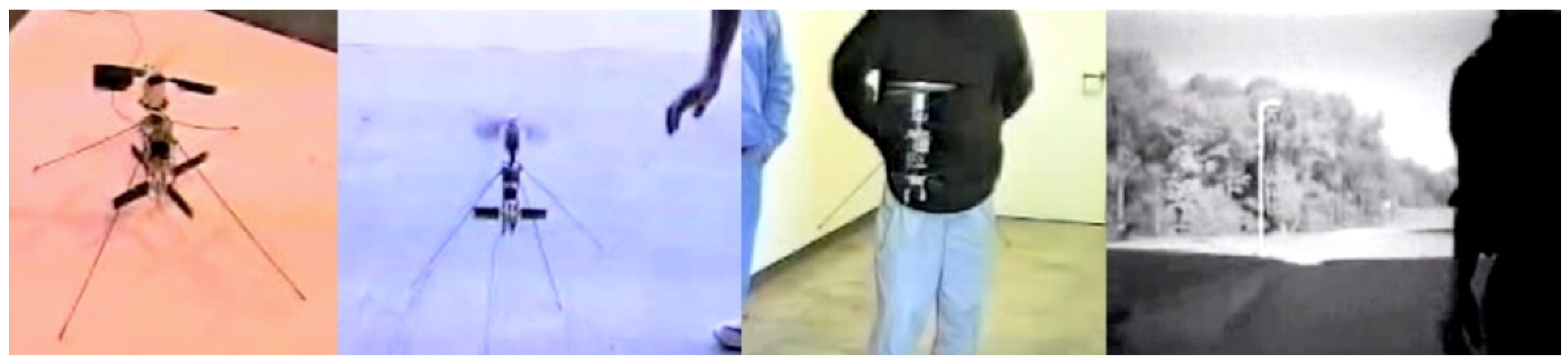
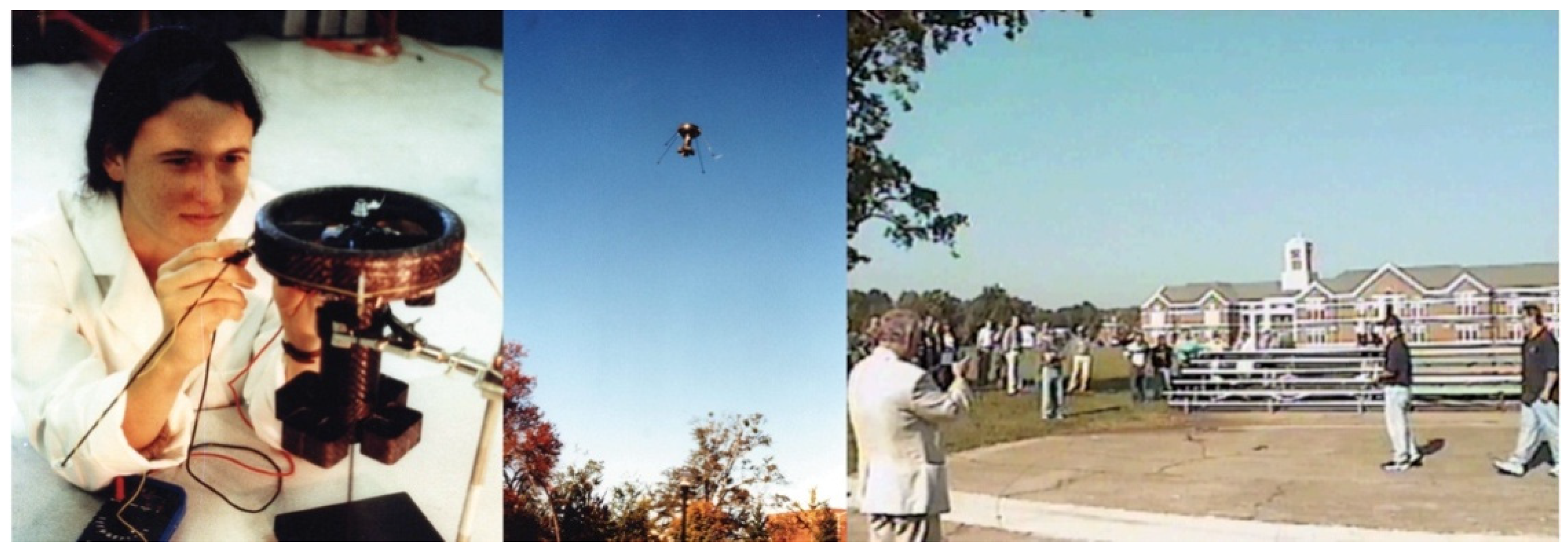
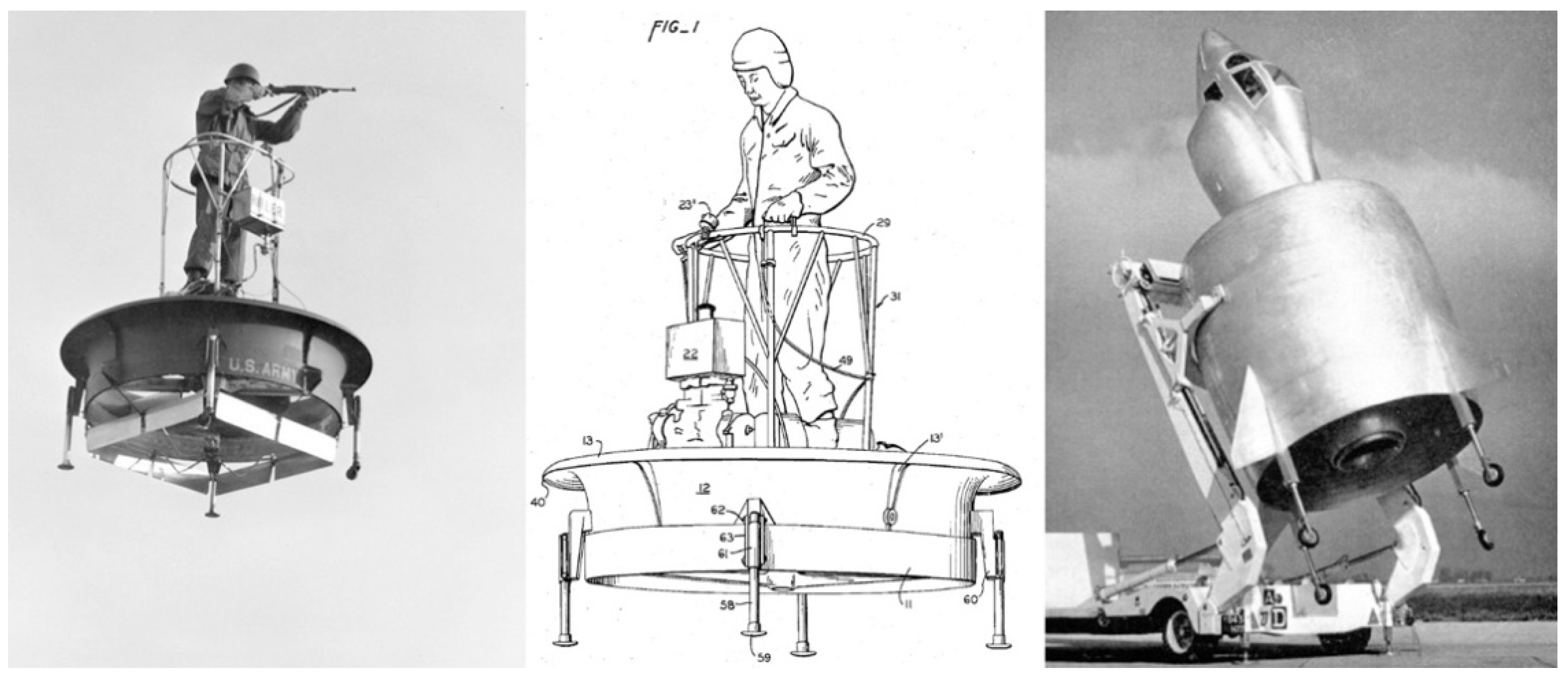
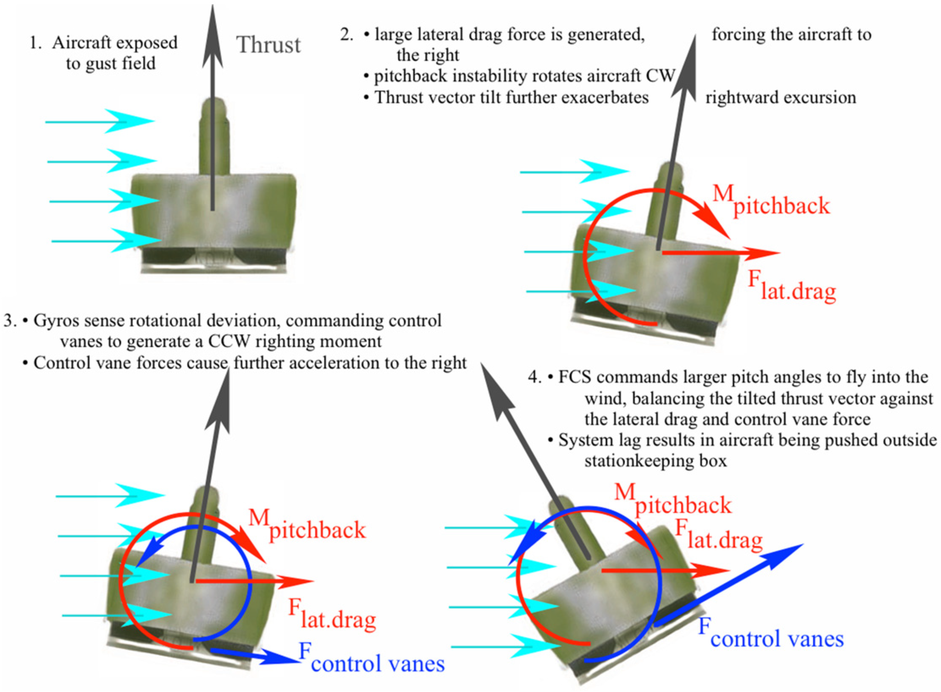
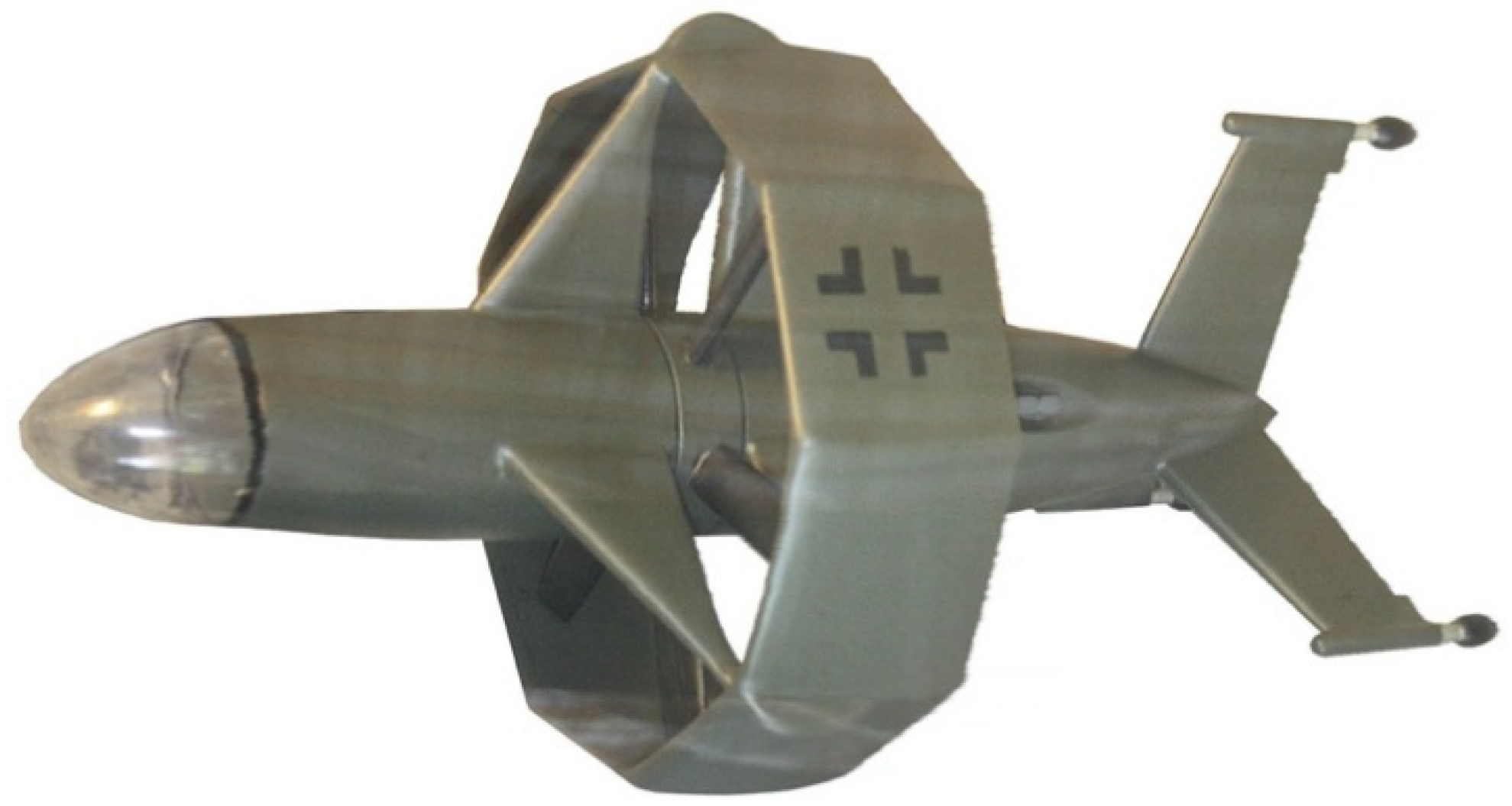
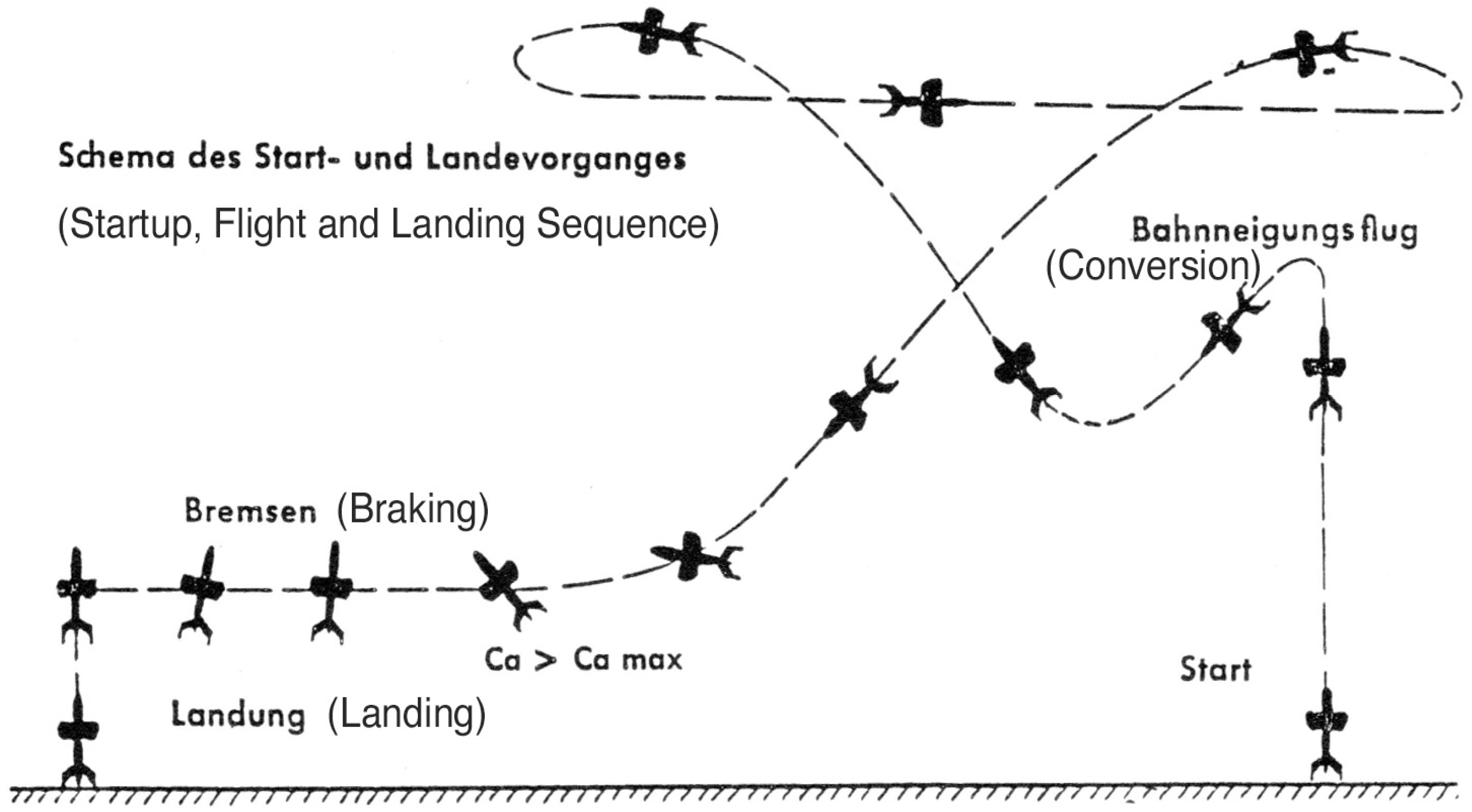
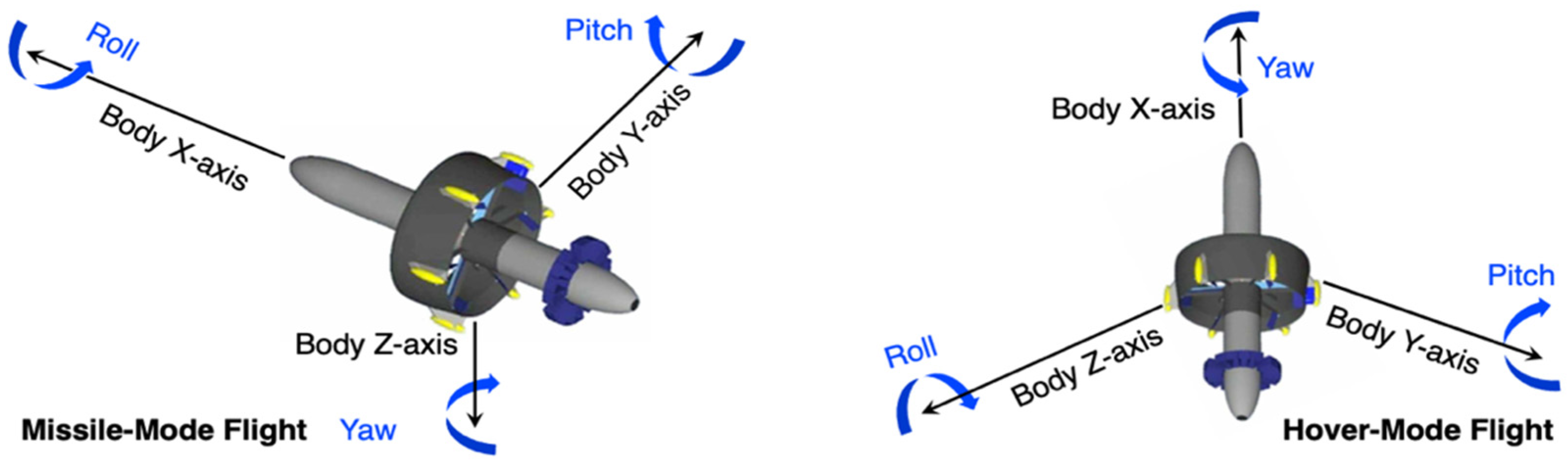
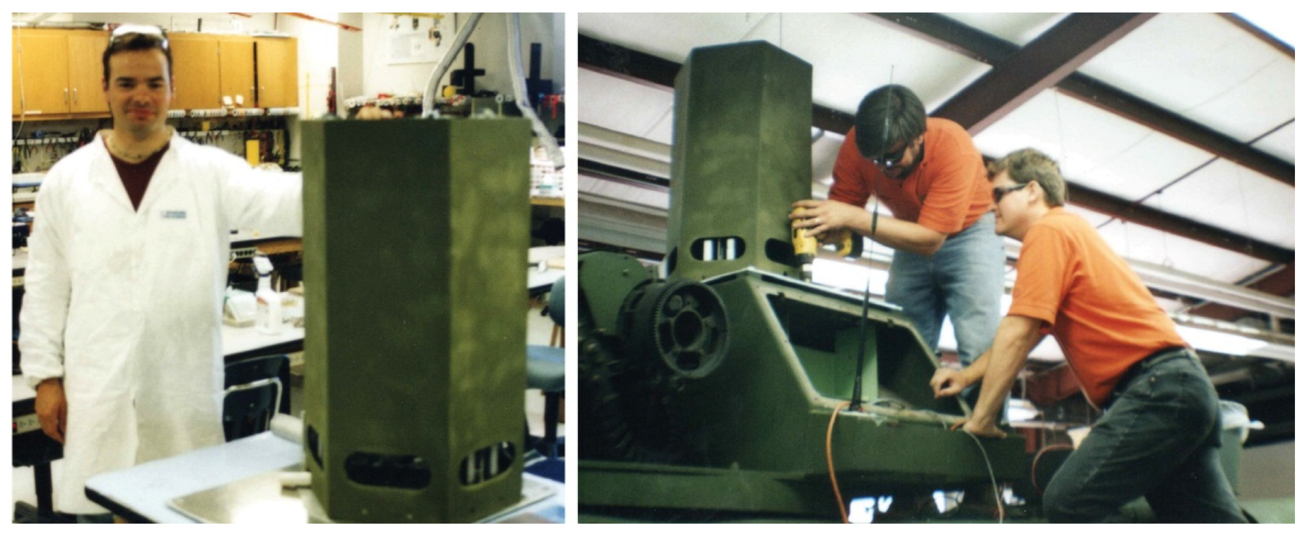
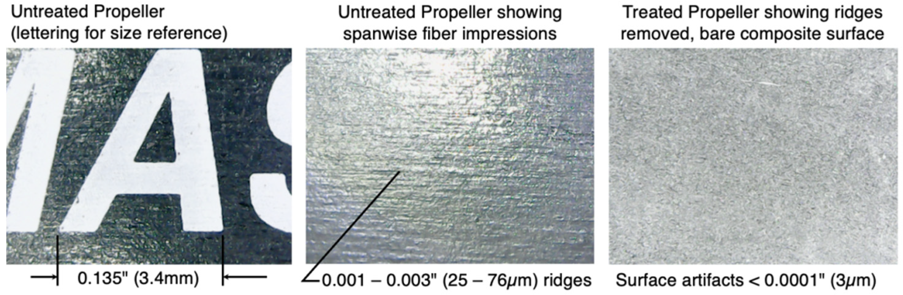
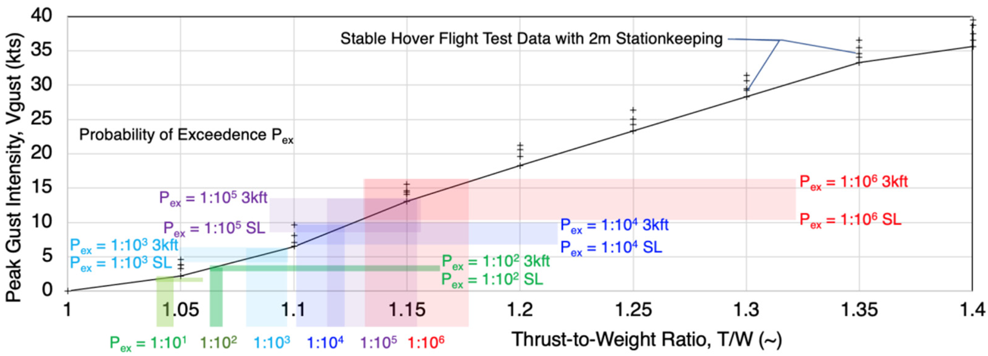
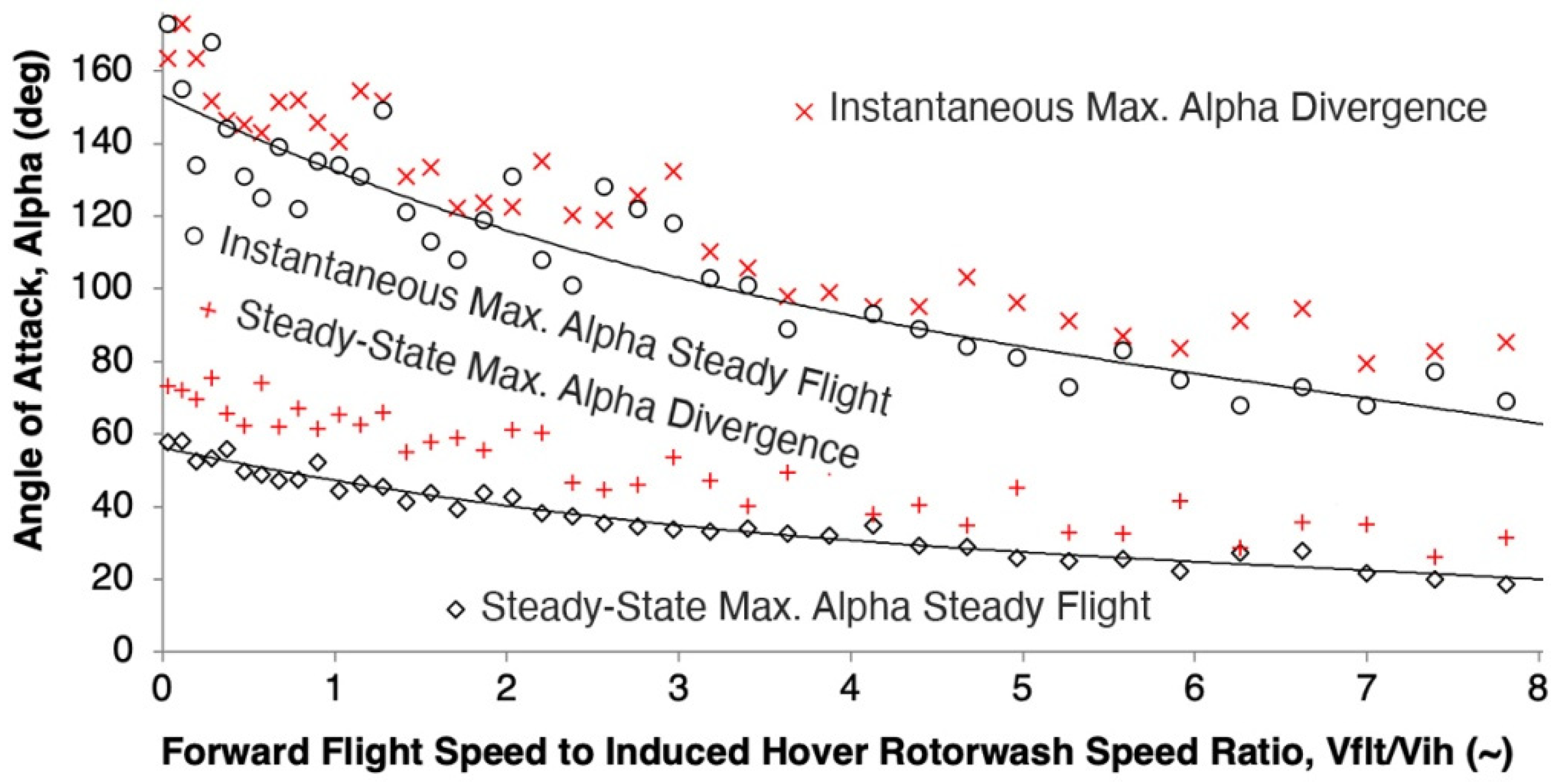
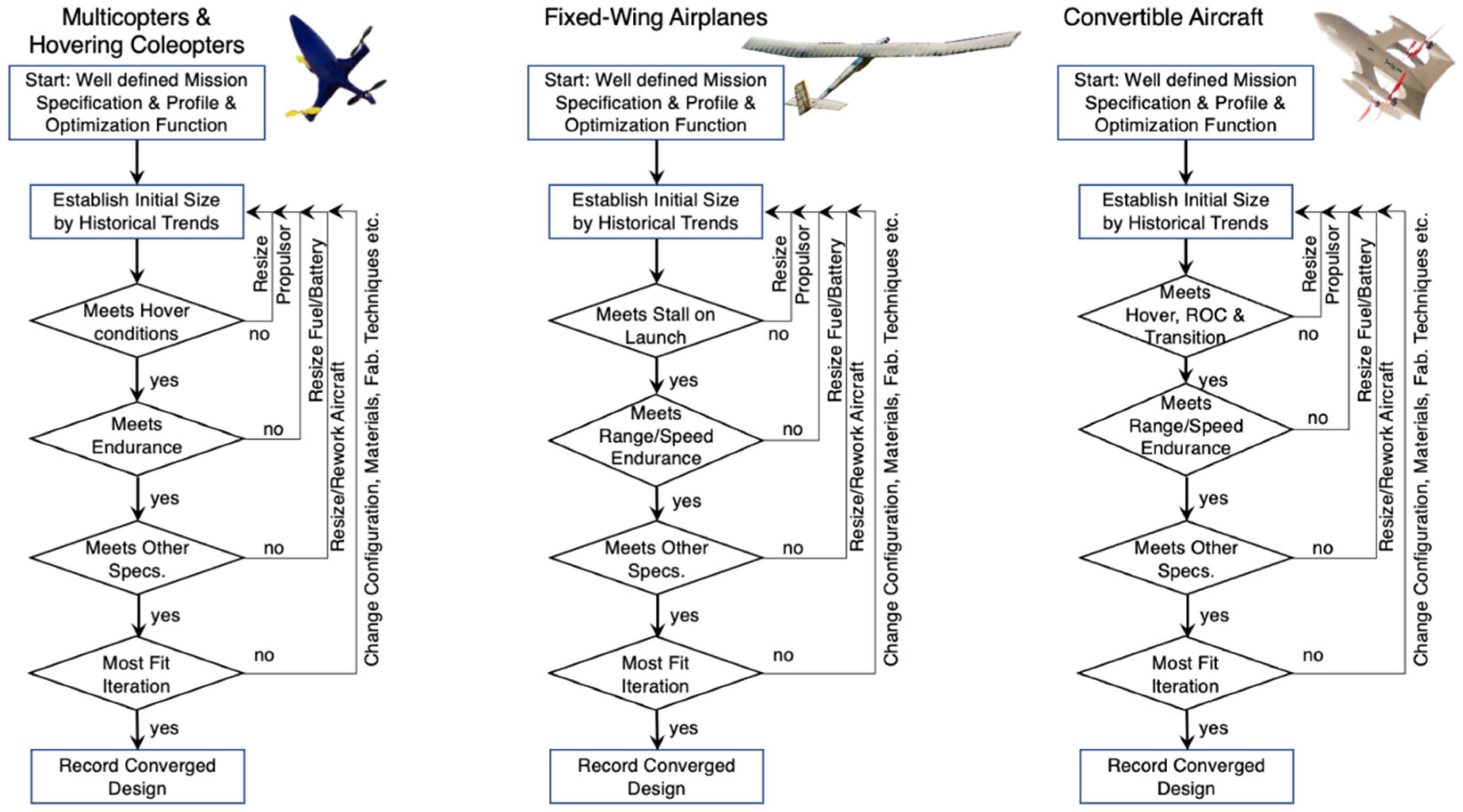
Table 1.
Weights and weight fractions of three members of the XQ-138 family of coleopters.
| XQ-138(11) | XQ-138(6) | XQ-138(4) | |||||||
|---|---|---|---|---|---|---|---|---|---|
| Mass | WTO | WOE | Mass | WTO | WOE | Mass | WTO | WOE | |
| (g) | Fraction | Fraction | (g) | Fraction | Fraction | (g) | Fraction | Fraction | |
| Structure | 771 | 31.4% | 46.9% | 136 | 36.0% | 46.3% | 44 | 38.1% | 41.7% |
| fuselage and rotor guard | 607 | 24.7% | 36.9% | 103 | 27.2% | 35.0% | 29 | 25.1% | 27.5% |
| muffler hard points | 12 | 0.5% | 0.7% | 4 | 1.1% | 1.4% | 3 | 2.6% | 2.8% |
| grid fins | 36 | 1.5% | 2.2% | 6 | 1.6% | 2.0% | 2 | 1.7% | 1.9% |
| undercarriage | 78 | 3.2% | 4.7% | 13 | 3.4% | 4.4% | 4 | 3.5% | 3.8% |
| fasteners | 28 | 1.1% | 1.7% | 5 | 1.3% | 1.7% | 2 | 1.7% | 1.9% |
| servo x-frame | 5 | 0.2% | 0.3% | 2 | 0.5% | 0.7% | 1 | 0.9% | 0.9% |
| mechanical and electrical conn. | 5 | 0.2% | 0.3% | 3 | 0.8% | 1.0% | 3 | 2.6% | 2.8% |
| Flight Control Actuators | 50 | 2.0% | 3.0% | 9 | 2.4% | 3.1% | 3.4 | 2.9% | 3.2% |
| pitch and yaw servos | 4 | 0.2% | 0.2% | 1 | 0.3% | 0.3% | 0.3 | 0.3% | 0.3% |
| p&y servo fasteners, wires, etc. | 10 | 0.4% | 0.6% | 2 | 0.5% | 0.7% | 0.6 | 0.5% | 0.6% |
| roll servos | 12 | 0.5% | 0.7% | 2 | 0.5% | 0.7% | 1 | 0.9% | 0.9% |
| roll servo fasteners, wires, etc. | 24 | 1.0% | 1.5% | 4 | 1.1% | 1.4% | 1.5 | 1.3% | 1.4% |
| Propulsion | 464.65 | 18.9% | 28.3% | 73 | 19.3% | 24.8% | 30 | 26.0% | 28.5% |
| Nvl 061, OS-32, BME-80 engines | 256 | 10.4% | 15.6% | 42 | 11.1% | 14.3% | 16 | 13.9% | 15.2% |
| starter | 98 | 4.0% | 6.0% | 10 | 2.6% | 3.4% | 2 | 1.7% | 1.9% |
| throttle linkage | 6 | 0.2% | 0.4% | 2 | 0.5% | 0.7% | 1 | 0.9% | 0.9% |
| trapped fuel and oil | 4.65 | 0.2% | 0.3% | 2 | 0.5% | 0.7% | 1 | 0.9% | 0.9% |
| fuel tank, filler and lines | 32 | 1.3% | 1.9% | 5 | 1.3% | 1.7% | 2 | 1.7% | 1.9% |
| muffler and silicone diverter | 22 | 0.9% | 1.3% | 4 | 1.1% | 1.4% | 3 | 2.6% | 2.8% |
| Rotor | 28 | 1.1% | 1.7% | 5 | 1.3% | 1.7% | 3 | 2.6% | 2.8% |
| throttle servo | 18 | 0.7% | 1.1% | 3 | 0.8% | 1.0% | 2 | 1.7% | 1.9% |
| SAS/Coms/Power Package | 357.2 | 14.5% | 21.7% | 76 | 20.1% | 25.9% | 28 | 24.3% | 26.6% |
| autopilot, gyros and mounts | 185 | 7.5% | 11.3% | 40 | 10.6% | 13.6% | 15 | 13.0% | 14.2% |
| receiver and mounts | 62 | 2.5% | 3.8% | 12 | 3.2% | 4.1% | 6 | 5.2% | 5.7% |
| power switch | 5.6 | 0.2% | 0.3% | 4 | 1.1% | 1.4% | 1 | 0.9% | 0.9% |
| substrate and connectors | 8.6 | 0.3% | 0.5% | 2 | 0.5% | 0.7% | 2 | 1.7% | 1.9% |
| power conditioning | 48 | 2.0% | 2.9% | 9 | 2.4% | 3.1% | 2 | 1.7% | 1.9% |
| SAS batteries | 48 | 2.0% | 2.9% | 9 | 2.4% | 3.1% | 2 | 1.7% | 1.9% |
| Sensor/Payload | 85 | 3.5% | 5.2% | 15 | 4.0% | 5.1% | 0 | 0.0% | 0.0% |
| primary payload/camera | 15 | 0.6% | 0.9% | 3 | 0.8% | 1.0% | 0 | 0.0% | 0.0% |
| primary video transmitter | 46 | 1.9% | 2.8% | 8 | 2.1% | 2.7% | 0 | 0.0% | 0.0% |
| video batteries | 24 | 1.0% | 1.5% | 4 | 1.1% | 1.4% | 0 | 0.0% | 0.0% |
| Fuel | 730 | 29.7% | 44.4% | 69 | 18.3% | 23.5% | 10 | 8.7% | 9.5% |
| MGWTO (gmf, lbf, %) | 2457.9 | 100.0% | 100.0% | 378 | 100.0% | 100.0% | 115.4 | 100.0% | 100.0% |
| WOE (gmf, lbf, %) | 1642.9 | 66.8% | 294 | 77.8% | 105.4 | 91.3% | |||
Publisher’s Note: MDPI stays neutral with regard to jurisdictional claims in published maps and institutional affiliations. |
© 2022 by the author. Licensee MDPI, Basel, Switzerland. This article is an open access article distributed under the terms and conditions of the Creative Commons Attribution (CC BY) license (https://creativecommons.org/licenses/by/4.0/).
Share and Cite
MDPI and ACS Style
Barrett-Gonzalez, R. High Performance Convertible Coleopter Drones. Drones 2022, 6, 346. https://doi.org/10.3390/drones6110346
AMA Style
Barrett-Gonzalez R. High Performance Convertible Coleopter Drones. Drones. 2022; 6(11):346. https://doi.org/10.3390/drones6110346
Chicago/Turabian StyleBarrett-Gonzalez, Ronald. 2022. "High Performance Convertible Coleopter Drones" Drones 6, no. 11: 346. https://doi.org/10.3390/drones6110346