Article

Flying Washer: Development of High-Pressure Washing Aerial Robot Employing Multirotor Platform with Add-On Thrusters

by
Ryo Miyazaki
1,*,
Hannibal Paul
2,
Takamasa Kominami
2,
Ricardo Rosales Martinez
2 and
Kazuhiro Shimonomura
2,*
1
National Institute of Advanced Industrial Science and Technology (AIST), Tsukuba 305-8560, Japan
2
Department of Robotics, Ritsumeikan University, Kusatsu 525-8577, Japan
*
Authors to whom correspondence should be addressed.
Drones 2022, 6(10), 286; https://doi.org/10.3390/drones6100286
Submission received: 1 September 2022 / Revised: 29 September 2022 / Accepted: 29 September 2022 / Published: 2 October 2022
(This article belongs to the Special Issue Applications of UAVs in Civil Infrastructure)

Abstract

:
In this study, we propose a multirotor aerial robot for high-pressure washing tasks at high altitudes. The aerial robot consists of a multirotor platform, an add-on planar translational driving system (ATD), a visual sensing system, and a high-pressure washing system. The ATD consists of three ducted fans, which can generate force in all directions on the horizontal plane. The ATD also allows the multirotor to suppress the reaction force generated by the nozzle of a high-pressure washing system and inject water accurately. In this study, we propose a method to precisely inject water by installing an ATD in the multirotor and using its driving force to suppress the reaction force and move the multirotor while keeping its posture horizontal. The semi-autonomous system was designed to allow the operator to maneuver the multirotor while maintaining a constant distance from the wall by the sensor feedback with onboard LiDAR or stereo camera. In the experiment, we succeeded in performing the high-pressure washing task in a real environment and verified that the reaction force generated from the nozzle was actually suppressed during the task.

1. Introduction

In recent years, multirotor unmanned aerial vehicles (UAV) have been used in a wide range of fields, including civil engineering, agriculture, industrial infrastructure, security, and remote sensing. In addition, as a next-generation application, research and development on “aerial manipulation” are being conducted all over the world to realize high-altitude work with physical contact by mounting a robotic arm on a multirotor, which is called an “aerial manipulator” [1,2]. The development of aerial manipulators is expected to be applied to work at heights, including the inspection of industrial infrastructures, such as bridges, high-voltage power lines, tunnels, wind turbines, and dams. The work area of the multirotor in aerial manipulation is divided into upper, lateral, and lower parts of the aircraft [3]. Perching, twisting work at high places [4,5], and percussion inspection work on walls [6] have also been reported. However, the typical type of multirotor requires tilting the body frame to generate thrust in the horizontal direction. In addition, the posture is tilted when horizontal forces are generated, such as horizontal movement, braking, and maintaining the aircraft position against crosswinds. The motion changes the position and attitude of the end-effector mounted on the multirotor while positioned on the horizontal plane. Moreover, to generate a stable force on the target object, it is necessary to keep the multirotor in a tilted position, and it can cause the multirotor to crush. Thus, to improve the performance of the aerial manipulator, realizing independent position and attitude control need to be realized.
To perform the position and attitude control of a multirotor independently, which is impossible with a typical multirotor, several studies on novel platform development are reported. A method in which the propeller of a multirotor is tilted from the horizontal plane has been theoretically analyzed [7], developed [8], and performed outdoors [9]. The other method in which the propeller is equipped with a single [10] or multi [11] tilt mechanism that can exert a wrench in any orientation while maintaining efficient flight configurations is presented. Moreover, a novel multi-linked type of multirotor is developed [12] and used to perform a manipulation task [13]. In these studies, new aerial robot hardware structures and control techniques are needed to put them to practical use.
On the other hand, many flight controllers that can fly typical multirotors with high stability are already on the market and are widely being used. Therefore, we focused on utilizing a typical multirotor and proposed an add-on planar translational driving system (hereafter, ATD), which consists of three ducted fans arranged to generate thrust in the horizontal direction and is able to translate the multirotor by keeping the attitude horizontal [14]. In addition, the design of the controller is very simple, and fine positioning can be easily achieved. By retrofitting the ATD to a commercially available and reliable multirotor platform, the performance can be enhanced, which requires aerial manipulation, such as accurate positioning and stable force generation for the manipulation task. Therefore, it is expected to be applied to various types of tasks at high altitudes.
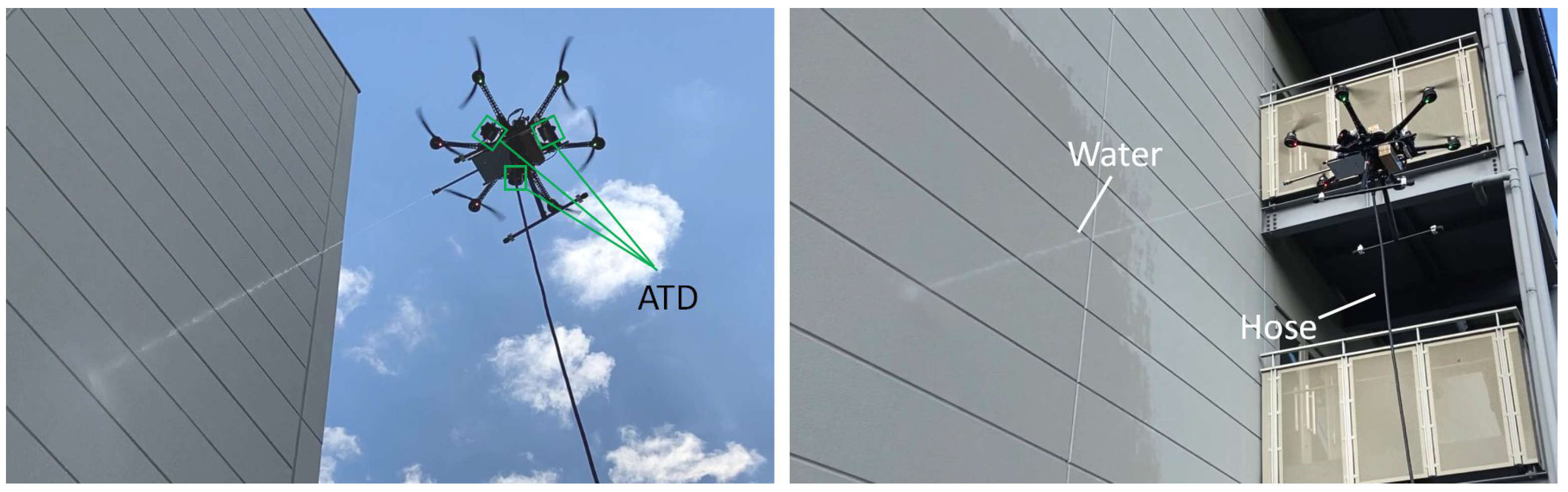
In this study, we focused on a high-pressure washing task (see Figure 1), which is one of the applications employing ATD. High-pressure washing tasks at high altitudes are usually carried out using a crane or cable-suspended gondola, and it is a very dangerous operation for the workers, with the risk of crashing [15]. Thus, it can effectively reduces accidents by replacing workers with multirotors. In order to realize the high-pressure washing task, it is necessary to generate an appropriate force to support the high-pressure washer nozzle while injecting water and to accurately inject water toward the target location. In [16], a three-dimensional hybrid kinematics-force (HKF) model for fluid force estimation coupled with position optimization of an aerial robot capable of high-pressure fluid ejection is presented. The reaction force from the water ejection is suppressed by the UAV body itself. In our case, by installing the ATD on the multirotor platform, the driving force from the ATD allows the multirotor to suppress the reaction force from the high-pressure washer and translates the multirotor by staying horizontal. A case in which a vertical propeller was added to a multirotor UAV so that it could generate horizontal force to conduct a percussion inspection was reported [17]. In our case, it requires a multirotor to generate a stable horizontal force in all directions.
In this study, we mainly redesigned the ATD and developed a multirotor system for high-pressure washing tasks. The system was designed for performing washing tasks semi-autonomously; it allows the multirotor to keep a constant distance from the target while facing perpendicular to the wall. The design concepts of the proposed multirotor are presented in Section 2. Section 3 presents the configuration of the designed system. Section 4 presents the sensor feedback of the multirotor for the washing task. Section 5 evaluates the outdoor experiment to verify if the reaction force is actually suppressed and if the attitude of the multirotor was kept horizontal while spraying the water. In addition, we also performed a washing task in a real environment for the validity of the proposed system. Section 6 concludes this paper and discusses future work.

2. Design Concept

2.1. Challenges in High-Pressure Washing Tasks

The following issues need to be addressed in order to realize high-pressure washing tasks using a multirotor platform. First, as shown in Figure 2A, the high-pressure washer generates a force in the direction of retracting the multirotor when water is injected. In order to maintain the position of the multirotor while injecting water, the multirotor must be tilted, but it changes the direction of the water injection. One way to maintain the position of the multirotor without changing its posture is to add an extra thruster. Second, a single thruster is sufficient to inject water while the multirotor is hovering, but it requires the multirotor to generate force in an oblique direction in order to perform the washing task while moving the multirotor, as shown in Figure 2B. In this case, the add-on thruster is required to be able to generate force in all directions on the horizontal plane.
In order to address the issues described above, in this study, we propose a method of installing an ATD in a multirotor. The ATD consists of three ducted fans and is placed perpendicular to the multirotor. The three ducted fans are the minimum configuration to keep the multirotor attitude horizontal and translate in all directions. In addition, the ATD can be installed at a height close to the center of gravity of the multirotor so that they can be moved without interfering with each other. On the other hand, the nozzle of the high-pressure washer can be placed at the same height as the ATD, and the driving force of the ATD can suppress the force generated during water jetting. Furthermore, since the ATD can generate force in all directions in the horizontal plane, it can move the multirotor while injecting water. Thus, the multirotor is equipped with ATD to suppress the force generated when water is injected, and since it can inject water without changing its posture while translating, the operator can easily apply water to targeted areas during washing tasks.

2.2. Measurement of Force in High-Pressure Washing

In order to design the ATD, it is necessary to check how much force will be applied to the multirotor during water injection. In addition, to determine the optimal distance between the multirotor and the washing target, the washing power of the water jet was also measured. The experimental setup of the force measurement is shown in Figure 3A and is conducted with reference to [16]. The high-pressure water pump used in the washing system is a Karcher K2 Classic with a maximum permissible pressure of 8 MPa, a discharge water volume of 330 L/h, with a motor of 1 kW. The nozzles of the high-pressure cleaner are attached with a turbo nozzle lance and are equipped with a slider that can push the force gauge. The measured force from the force gauge ( F 1 , see Figure 3A) can be equal to the force acting on the multirotor. Four different types of nozzles (0 , 15 , 25 , 40 , see Figure 3A) were used for the measurements. To measure the washing force ( F 2 , see Figure 3A), we set a force sensor at the same height as the nozzle. Measurements were taken while increasing the distance by 0.5 m.
The measurement results are shown in Figure 3B,C. Figure 3B shows the generated force while injecting the water. When the high-pressure pump was switched on, a constant force was generated in about 0.5 s, and when it was switched off, the force disappeared within 0.5 s. When the nozzle is at 0 degrees, a constant force of about 3 N is generated, and when the nozzle is at 15, 25, and 40 degrees, a steady force of about 5 N is generated. In our nozzle sets, the diagram of the spout of 0 degrees is 3.5 mm, and the others are 2.5 mm. This could be the reason why the 0-degree nozzle produced smaller measurement results than the other nozzles used. In addition, according to the measurement result, the water pressure can be calculated and was 7.4 MPa. Moreover, we also confirmed that the measurement result of F 1 did not change whether the water stream hits a wall or not. It is known that when the distance between the nozzle and the wall is sufficiently larger than the nozzle diameter, the reaction force of the water jet is almost constant. In this experiment, the nozzle diameter d was 3.5 mm (in the case of the 0-degree nozzle), the distance l between the nozzle and the wall was at least 0.5 m, and in the case of 0.5 m, it is l / d = 142.85 , which is a sufficiently large value. If the nozzle-to-wall distance is the same or less than the nozzle diameter, the reaction force should increase.
Figure 3C shows the relationship between washing power and the distance to the washing target. When the nozzle is at 0 degrees, the force showed a gradual decrease until 3 m and a sharp decrease after that. When the nozzle is at 15, 25, and 40 degrees, the force showed a sharp decrease until 1 m and a gradual decrease after that. Jet force ( F 2 ) is proportional to flow rate, velocity immediately after exiting the nozzle, and atmospheric velocity attenuation coefficient, which decreases with increasing injection distance. It is also considered that the larger the nozzle angle, the greater the water spread and the greater the decrease in impact force. In addition, in reference to the results in Figure 3B, the jet force is considered to be about 5 N just after the water is ejected from the nozzle. In other words, between 0 and 0.5 m, the larger the angle of the nozzle, the greater the attenuation of the jet force. Therefore, for the 0 type of nozzle, a constant distance between the nozzle and washing target can be set to less than 3 m. Moreover, for the 15 , 25 , 40 type of the nozzle, the distance from the nozzle to the wall should be set to less than 1 m to keep the washing power. Thus, if safety is also a consideration, the nozzle position must be extended from the multirotor, and a longer lance should be used.

2.3. Add-on Planar Translational Driving System

In this study, compared with our previous work [14], we improved the arrangement of the ducted fan in the ATD and made it fit inside the multirotor, as shown in Figure 4A,B and it is designed to be lighter and more compact. Table 1 shows the specification of the designed ATD, and the total weight of the ATD is 0.83 kg, including the ESC. According to force measurement results (see Figure 3), we used the ducted fan, which can generate a maximum thrust of 1.3 kg with a diameter of 70 mm; this much thrust can be enough to suppress the force while injecting the water. These ducted fans are arranged in a configuration so that they are mounted at 120 degrees in the horizontal plane around the UAV and set at a height close to the center of gravity of the multirotor so as not to generate movement in the vertical direction. The model of the ATD is shown in Figure 4C and represents the area of the driving force that the ATD can generate with the roll and pitch directions of the aircraft as the reference coordinate system. The region of the force vector that can be generated from any two ducted fans can be divided into S 1 , S 2 , and S 3 and is shown in the following equation.
S 1 : = { F 2 F = α F 1 + β F 2 ; α , β 0 ; α + β 1 }
S 2 : = { F 2 F = α F 1 + β F 3 ; α , β 0 ; α + β 1 }
S 3 : = { F 2 F = α F 2 + β F 3 ; α , β 0 ; α + β 1 }
In order to control the ATD, it is necessary to find the force output of each ducted fan for any desired output force F. Thus, the force F can be determined in the regions of S 1 , S 2 , and S 3 , and the output F 1 , F 2 , and F 3 of each ducted fan can be obtained as follows.
A = k 1 k 1 0 0 ( F S 1 ) 2 k 0 0 0 k 1 ( F S 1 ) , F 1 F 2 F 3 = A F x F y 0 0 2 k 0 k 1 ( F S 3 )
± k is the slope of each region in the coordination(see Figure 4C), and in our case, it is ± 3 / 3 because the ducted fans are displaced by 120 degrees. The input thrust of the ducted fan u i with its output thrust F i follows u i F i , and can be defined by the following equation.
F i = ζ u i + C ( 0 u i 100 , i = 1 , 2 , 3 )
To verify ζ and C, we measure the output force of the ATD by pushing the force gauge. The thrust input of the ducted fan was set at 80% and reduced by 5% to 20%. The output force data were recorded for a duration of 3 s for each input. Figure 4D shows the measurement result. According to the result, an asymptotic line can be found by the output value at each input. Thus, ζ and C can be estimated by 0.1319 and −0.0706, respectively.

3. Configuration of the Aerial Robot System

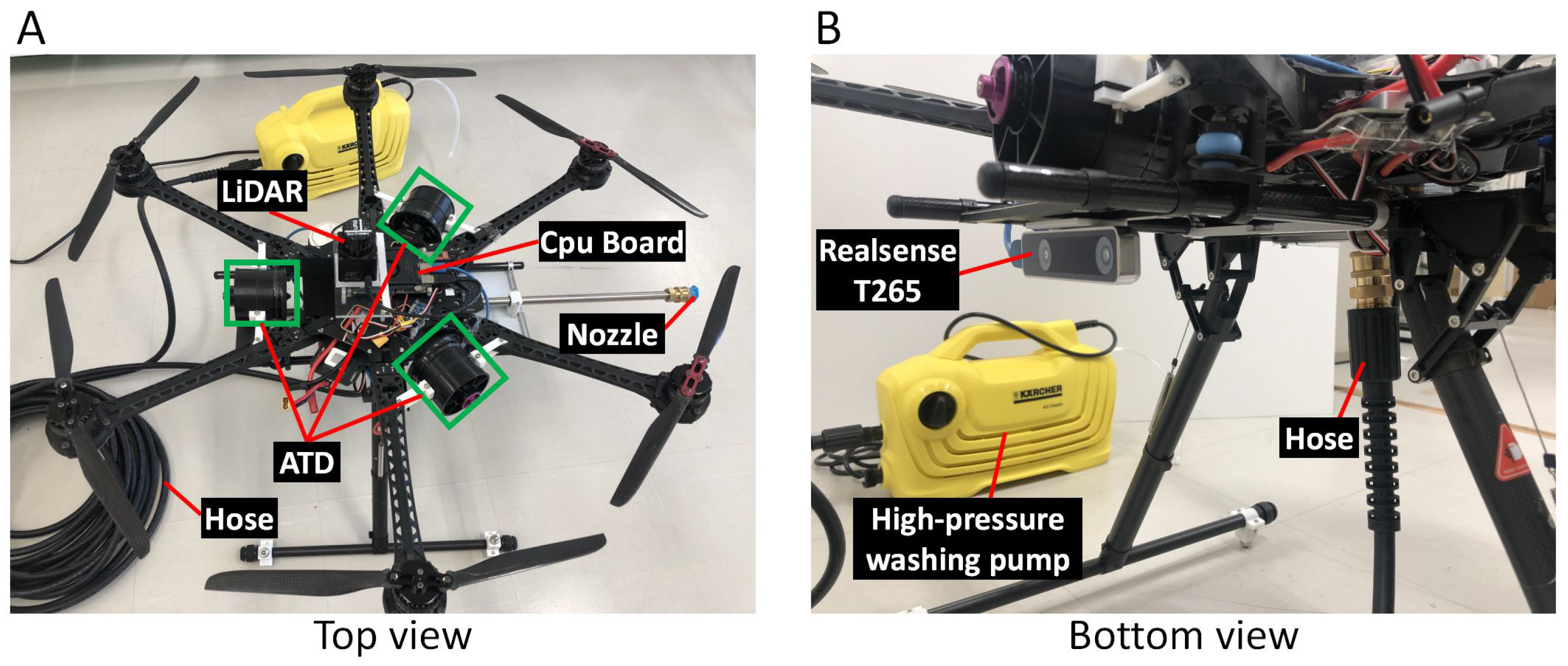
The proposed aerial robot is shown in Figure 5. The robot consists of a multirotor platform, an onboard computer with sensors (a LiDAR and a stereo camera), and a high-pressure washing system; the ATD module, described in Section 2, is mounted on the multirotor, as shown in Figure 5A. The multirotor platform used is a DJI S800 (DJI, Guangzhou, China) airframe with a DJI A3 (DJI, Guangzhou, China) flight controller. The frame diameter of the airframe and propeller is 0.8 m and 0.38 m, respectively. The onboard computer is a LattePanda Alpha 864 (DFRobot, Shanghai, China), which is used to control the multirotor, ATD, and position estimation. The multirotor is equipped with a Realsense T265 stereo camera for multirotor position feedback. The LiDAR used is a URG-04LX-UG01 for detecting the washing target surface and the angle between the multirotor and wall. The nozzle lance is fixed with the roll direction of the multirotor, and the water supply hose is designed to be connected to another side of the turbo nozzle lance, as shown in the right figure of Figure 5B.
The proposed aerial robot system was constructed as shown in Figure 6. The control system of the multirotor and the ATD are designed to be operable from the RC transmitter via the onboard computer. The flight controller and the onboard computer communicate via SDK. It allows the flight status to be received from the flight controller and sends control commands from the onboard computer. Control inputs to the multirotor include roll angle u r o l l , pitch angle u p i t c h , yaw angular velocity u y a w , throttle u t h r o t t l e , and brake functions u b r e a k . The ATD is equipped with an I2C interface (PCA9685), which receives control input from the onboard computer and controls the ducted fans through ESC. The low level control system is constructed based on Equations (1)–(5) and is designed so that ATD control can be achieved by providing input thrust in the roll and pitch directions only ( u = [ u x u y ] T ). Thus, we designed flight control modes by using the above-mentioned control inputs, and can be handled by a switch in the RC transmitter, namely normal control mode and ATD control mode. These control modes are described as follows:
  • Normal control mode: It allows the operator to control the multirotor manually, which is the same as typical operation. Control inputs of the multirotor with ATD can be given as follows
    u b r a k e = 1 , u r o l l = K θ m a x u c h 1 , u p i t c h = K θ m a x u c h 2 u y a w = K y a w u c h 3 u t h r o t t l e = K t h u c h 4 u = [ 0 0 ] T ( u c h 5 = 1 )
  • ATD control mode: It allows the operator to control the multirotor semi-autonomously and translate it with the fixed attitude of the airframe. The ATD controller is designed based on the RC input of joysticks and sensor feedback (LiDAR or stereo camera) for operating the multirotor and keeping a constant distance between the multirotor and the washing target. A brake function of ATD is designed by using velocity data from the stereo camera to stop the multirotor immediately after the operation. Furthermore, a reasonable fixed input value is added to the ATD controller in order to suppress the reaction force during water injection. The control inputs of the multirotor with ATD can be given as follows.
    u b r a k e = 0 , u r o l l = 0 , u p i t c h = 0 u y a w = K p y a w e y a w + K d y a w e ˙ y a w u t h r o t t l e = K f t h e z K v z v z u = K f m a x u c h 1 K v v x K f m a x e y K v v y + u e q ( u c h 5 = 0 )
In Equations (6) and (7), u c h i ( i = 1 , 2 , , 5 ) is the input value of the control stick from the RC transmitter converted to a range of ± 1 . In Equation (6), K θ m a x and K t h are parameters to make the input range of the RC transmitter correspond to the maximum output range of the multirotor. The parameters were set to enable input of a maximum of 25 deg in the roll and pitch directions and a maximum of 2 m/s in the vertical direction. In Equation (7), K p y a w and K d y a w are the control gain of the PD controller on the yaw axis and decided to be experimental. e y a w can be calculated by the IMU sensor from the flight controller or LiDAR sensing. u e q is an input value to suppress the reaction force during water jetting. Based on the force measurement results shown in Figure 3B and Figure 4D, we set u e q to generate a thrust force of 3 to 5 N during water jetting. e y indicates the error between the target position and the current position (same direction as water jetting), which can be calculated by odometry of a stereo camera or LiDAR sensing. To keep the multi-rotor at its current height when not in operation, we designed position error e z , which is in the vertical direction as follows.
e z = P t a r z P z ( u c h 4 = 0 ) u c h 4 ( u c h 4 0 ) , P t a r z = P z ( u c h 4 0 )
In Equation (8), P t a r z and P z show the target position and the current position in the vertical direction, respectively.

4. Sensing System for Position Control

To control the multirotor semi-autonomously, the sensor feedback from the LiDAR (see Figure 5A) and the stereo camera (see Figure 5B) can be used. If the washing target is a wall, LiDAR can be used to find its angle and the distance to the wall in front of the UAV. However, the LiDAR can not work correctly if the washing target has the property of being reflective or passing light such as glass or metals. In this case, odometry data from the stereo camera can be used if the initial positional relationship between the multirotor and the washing target is known.
In the case of using LiDAR, the data from the LiDAR is obtained in the form of a 1D array. The array size depends on the angular resolution and view angle of the LiDAR. Each of the array elements corresponds to the distance from the center of the LiDAR to the object at that particular angle in meters. In this study, we used URG-04LX-UG01 (Hokuyo, Japan), with an angular resolution of 0.352 degrees and a total view range of 240 degrees. It is capable of detecting objects from 0.02 to 4 m at 1 mm accuracy. If the distance at a given angle is more than 4 m, the value will be represented as infinity. These values are filtered and removed to obtain only the object distance in the visible range. It is difficult to process the data in 1D form, and, therefore, they are converted into points in a 2D plane using a 2D rotation matrix.
To obtain the information about the wall, it is necessary to detect and separate the wall from the obtained LiDAR data. We assume that when the algorithm starts, the wall is in front of the UAV because the operator activates the wall detection algorithm when it is actually in front of a wall and needs to be turned off otherwise. According to this assumption, segmentation is performed considering the point directly in front of the UAV as one of the points in the wall, moving to the points to the right from that seed point. By computing the distance between the neighboring points, it is decided whether to include the point in the segment or not. When a discontinuity is found, the procedure is repeated again, this time from the seed point to the points to its left. Once the visible wall segment is detected in the data, a linear least square fit is performed on the segmented data to fit a line onto it. This is assuming the detected wall segment is flat, and no other walls are connected to it in the visible range of the LiDAR data.
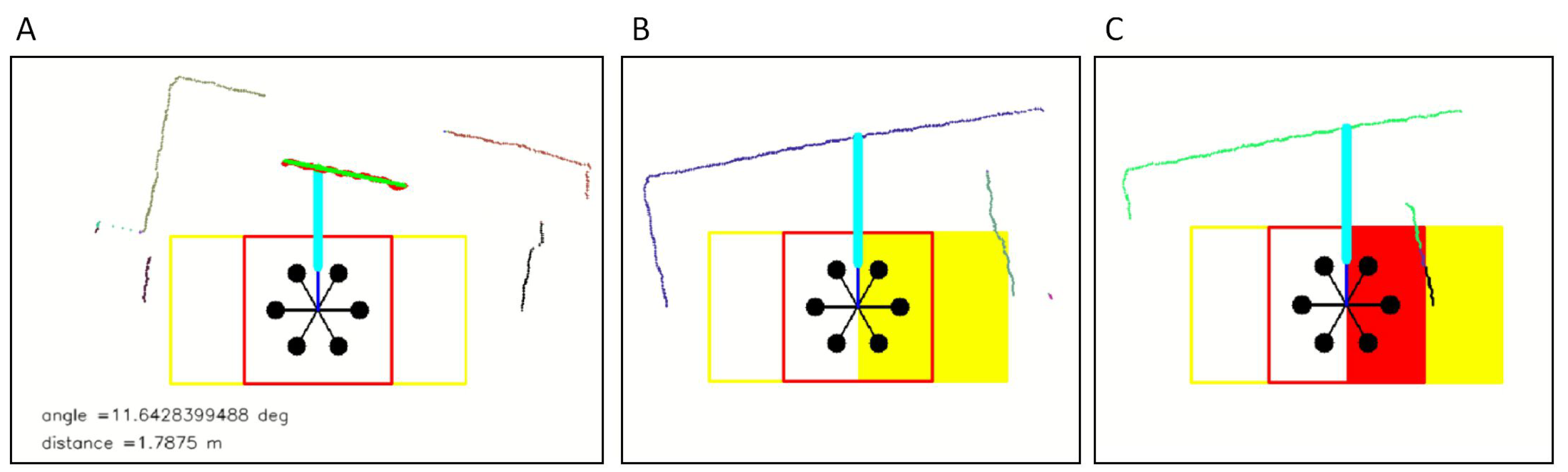
From the fitted line it is possible to find its angle and the distance to the wall (line segment) in front of the UAV. This information is necessary to angle the UAV and maintain the distance during washing. The results of these processes are shown in Figure 7.
However, in addition to the information about the wall, it is necessary to sense the obstacle around the UAV to avoid a crash. In order to do that, a rectangular region around the UAV is considered called the ‘warning region’ (2 m × 1 m). The size of the region depends on the size of the UAV. The width is considered wider than the height because the UAV moves sideways during washing and requires monitoring in sideward directions. If there are any obstacles sensed in this region (see Figure 7B), the UAV can be automatically controlled to move in the opposite direction. Another region, smaller than the above-mentioned region, is used as the ‘critical region’ (1 m × 1 m). If there are any obstacles in this region (see Figure 7C), the UAV is immediately made to halt to avoid a crash. The operator can take control over the UAV.
On the other hand, in the case of using the stereo camera, we used sensor feedback from the camera mounted on the bottom of the multirotor. In this study, we used a Realsense T265 camera. It includes two fisheye lens’, an image sensor, IMU sensor BMI055(Bosch, Germany) and Intel Movidius Myriad 2 VPU(Intel, America), and an optimized V-SLAM algorithm. Through the Intel Realsense SDK, we can get the odometry and IMU data. By measuring the distance between the wall and the initial position of the multirotor, we can estimate the current distance and angle to the wall while flying.
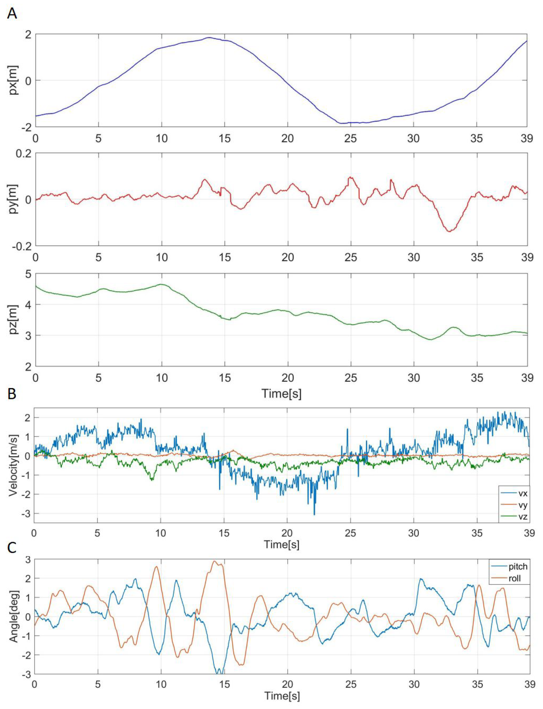
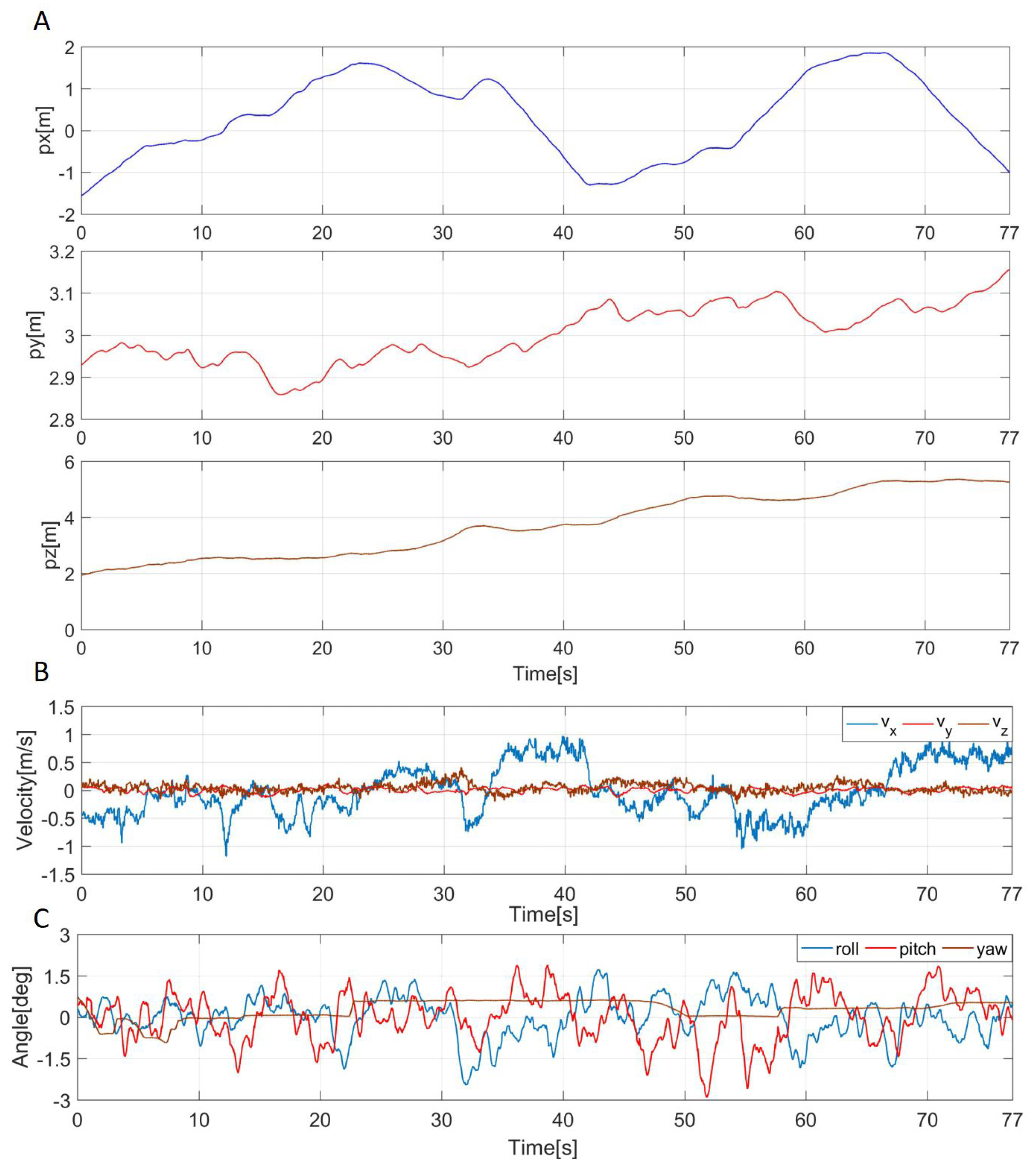
To verify the effectiveness while using LiDAR and the stereo camera as sensor feedback, we perform indoor experiments, as shown in Figure 8. The multirotor was controlled to keep a constant distance to the wall, and it was set to 1.6 m. The heading direction of the multirotor was set to stay vertical to the wall, and we operated the multirotor to move to the right (see Figure 8). In the experiment, we used LiDAR feedback at first and repeated the same experiment by using camera feedback. The experimental results are shown in Figure 9. In the case of using LiDAR (see Figure 9A), the position error was in ±0.05 m, and there was an error of about 0.05 m with the camera that took measurements at the same time. In addition, the multirotor was able to move while remaining perpendicular to the wall within an error range of about ±1 deg. The angle estimated from the IMU sensor had an error of about ±1 deg compared to the LiDAR but showed similar behavior. On the other hand, in the case of using camera feedback (see Figure 9B), the experimental results are similar to the case of using LiDAR feedback. Through the experiment, we verified that both the LiDAR and camera feedback can be used for multirotor control, and it worked as expected. Table 2 shows the pros and cons of different parameters of the two sensor systems used for testing.

5. Experiment

5.1. Water Injection Test While Flying

An outdoor flight experiment was conducted to confirm whether the developed aerial robot could move while maintaining a horizontal posture while suppressing the reaction force generated by the water jet. The experimental procedure was as follows: First, the multirotor was flown, and the flight mode was switched to ATD control mode. Then we turned on the high-pressure pump and started spraying water. After confirming the operation of the multirotor in the hovering state, the multirotor was moved in a zigzag route while maintaining its position in the water jet direction.
Figure 10 shows a continuous image of the multirotor movement (see Figure 10A) and its trajectory (see Figure 10B). During the experiment, the wind velocity was 2∼3 m/s. The experimental results are shown in Figure 11. Figure 11A shows a time series of the graph in Figure 10B. As shown in the figure, the position was controlled within a range of about ±0.05 m in the direction of the water jet (py). In addition, the position temporarily shifted by 0.2 m from the target position for 30 to 35 s. This was caused by the water hose getting caught on the fuselage, but it quickly converged to the target position and did not affect the flight. Figure 11B shows the velocity of the multirotor during water injection, which was estimated from the velocity data obtained from the stereo camera. During the flight, the velocity change in the direction of the water jet was within about ±0.05 m/s. Based on the above, it was confirmed that the reaction force generated during water jetting was actually suppressed. Figure 11C shows the attitude change of the multirotor during the flight. This result shows that the roll and pitch angles of the multirotor UAV changed within ±2 degrees during the flight, and the posture was kept almost horizontal.

5.2. Washing Task

In order to verify the effectiveness of the developed aerial robot for high-pressure washing tasks using the proposed method, a demonstration experiment was conducted in a real environment. The experimental procedure was the same as the water jetting experiment. A constant distance between the multirotor and the wall was set to 3 m. The multirotor was controlled to inject water vertically against the wall. Figure 12 shows a continuous image of the multirotor movement (see Figure 12A) and its trajectory (see Figure 12B). During the experiment, the wind velocity was 3∼4 m/s.
The experimental results are shown in Figure 13. Figure 11A shows a time series of the graph in Figure 12B. The multirotor was able to maintain its position with an accuracy of ±0.1 m relative to the target position. The error was larger than in the previous water jetting experiment, and the reason was that the wind velocity was larger than before. In addition, the wind velocity was not constant because the building blocked the wind in some areas. Figure 13B shows the velocity of the multirotor during water jetting; the velocity change in the direction of the water jet is within about ±0.05 m/s. It was confirmed that the reaction force generated by the water jetting was actually suppressed during the washing task. Figure 13C shows the attitude change of the multirotor during the flight. The roll and pitch angles of the multirotor UAV changed by ±2 degrees during the flight, and the posture was also considered as kept almost horizontal. The yaw value shown in the graph indicates the angle between the direction of the multirotor and the wall surface, which could be controlled with an error of about ±1 deg. In addition, according to the experiment results of water injection testing and washing task, the similarity of the two experimental results suggests that the reaction force generated by the water jet would be constant regardless of the presence or absence of a wall. On the other hand, it was confirmed that the developed aerial robot can perform high-pressure washing tasks up to 12 m from the ground (see Figure 14). This experimental video can be available at the Supplementary Materials. Moreover, the weight of the hose is 200 g/m, and considering the loadable weight of the UAV, it is estimated to be between 15 and 20 m. considering the weight of the UAV’s payload, 15 to 20 m seems to be the limit. Based on the above, it was verified that the proposed method can be used for washing tasks while facing the wall vertically and keeping a constant distance from the wall.

6. Discussions and Conclusions

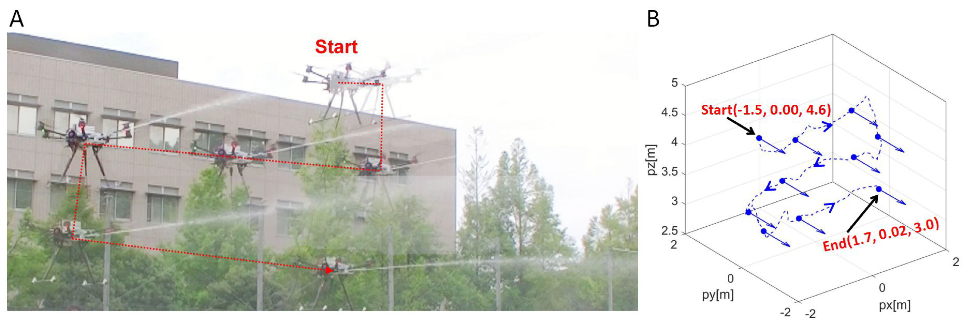
In this study, we proposed the application of a multirotor system to a high-pressure washing task. To achieve this, it is necessary to suppress the reaction force generated by the nozzle of the high-pressure washer while accurately spraying water. In order to solve these problems, we proposed a method of mounting an Add on Planar Translational Driving System (ATD) on a multirotor. By using the ATD, it allows the multirotor to move while maintaining a horizontal posture and to spray water accurately. In addition, the reaction force during water injection can be suppressed by the driving force of the ATD. Based on the proposed method, the force acting on the multirotor and the washing force during water jetting was measured. Then the ATD was developed based on the measurement results, and we measured the thrust of the ducted fan and confirmed that the reaction force of the water jet was within the range of the driving force of the ATD. Finally, the ATD and the nozzle of the high-pressure washer were mounted on the multirotor to construct the system. The sensing system was constructed using LiDAR and stereo cameras, and indoor experiments were conducted to verify the effectiveness of the sensor feedback. In the flight experiment, water jetting was performed while flying the multirotor in ATD flight mode, and it was confirmed that the aircraft could move while maintaining a horizontal attitude and, at the same time, suppressing the reaction force. Further demonstrations were conducted, and it was confirmed that the washing task can be performed while maintaining a constant distance and vertically facing the wall surface. Thus, the validity of the application of the proposed method to high-pressure washing tasks was verified.
In this study, we applied the multirotor system to a high-pressure washing task semi-autonomously. However, the motion planning and automation for mapping, positioning, and flying along the target trajectory for walls of various shapes will be future tasks. On the other hand, it was confirmed that the non-uniformity of wind velocity distribution during the washing task affects the positioning accuracy, and the robustness of the position control should be improved in the future. Meanwhile, we used stereo cameras and LiDAR separately depending on the situation, but by integrating these sensing data, it is possible to obtain more stable sensor feedback. On the other hand, in the flight experiment, for the length of the hose, the position of the UAV was not so far from the tank on the ground, and the hose was vertical; i.e., the hose extended straight down from the UAV to the ground and thence to the tank. Therefore, there was no significant hindrance to the UAV’s lateral movement or attitude maintenance. However, if the hose is more distant from the tank and at an angle, the UAV’s movement would be affected. This is an issue to be addressed in the future. If an automatic aerial high-pressure washing task is realized, it also can be used for fire extinguishing and painting operations, expanding the range of applications.

Supplementary Materials

The following are available at: https://www.mdpi.com/article/10.3390/drones6100286/s1, Video S1: Flying Washer.mp4.

Author Contributions

Contributions of the authors are as follows: R.M.: developed the proposed device, controllers, and system, designed and performed experiments, analyzed the data, and wrote the manuscript. H.P.: advised on the design concepts, developed the LiDAR sensing system, designed and performed experiments, and wrote the manuscript. T.K.: advised on the design concepts, and designed and performed experiments. R.R.M.: designed and performed experiments, and wrote the manuscript. K.S.: provided general ideas about the work, advised on the design of experiments, and wrote the manuscript. All authors have read and agreed to the published version of the manuscript.

Funding

This research is supported by Adaptable and Seamless Technology Transfer Program through Target-driven R&D (A-STEP) No. JPMJTM20PG from Japan Science and Technology Agency (JST).

Institutional Review Board Statement

Not applicable.

Informed Consent Statement

Not applicable.

Data Availability Statement

Not applicable.

Conflicts of Interest

The authors declare no conflict of interest.

References

  1. Ollero, A.; Tognon, M.; Suarez, A.; Lee, D.; Franchi, A. Past, Present, and Future of Aerial Robotic Manipulators. IEEE Trans. Robot. 2021, 38, 626–645. [Google Scholar] [CrossRef]
  2. Ruggiero, F.; Lippiello, V.; Ollero, A. Aerial Manipulation: A Literature Review. IEEE Robot. Autom. Lett. 2018, 3, 1957–1964. [Google Scholar] [CrossRef] [Green Version]
  3. Ladig, R.; Paul, H.; Miyazaki, R.; Shimonomura, K. Aerial Manipulation using Multirotor UAV: A Review from the Aspect of Operating Space and Force. J. Robot. Mechatron. 2021, 33, 196–204. [Google Scholar] [CrossRef]
  4. Thomas, J.; Loianno, G.; Daniilidis, K.; Kumar, V. Visual Servoing of Quadrotors for Perching by Hanging From Cylindrical Objects. IEEE Robot. Autom. Lett. 2016, 1, 57–64. [Google Scholar] [CrossRef] [Green Version]
  5. Shimahara, S.; Leewiwatwong, S.; Ladig, R.; Shimonomura, K. Aerial torsional manipulation employing multirotor flying robot. In Proceedings of the IEEE/RSJ International Conference on Intelligent Robots and Systems (IROS), Daejeon, Korea, 9–14 October 2016; pp. 1596–1600. [Google Scholar]
  6. Ikeda, T.; Yasui, S.; Minamiyama, S.; Ohara, K.; Ashizawa, S.; Ichikawa, A.; Fukuda, T. Stable impact and contact force control by UAV for inspection of floor slab of bridge. Adv. Robot. 2018, 32, 1061–1076. [Google Scholar] [CrossRef]
  7. Tognon, M.; Franchi, A. Omnidirectional Aerial VehiclesWith Unidirectional Thrusters: Theory, Optimal Design, and Control. IEEE Robot. Autom. Lett. 2018, 3, 2277–2282. [Google Scholar] [CrossRef] [Green Version]
  8. Park, S.; Lee, J.; Ahn, J.; Kim, M.; Her, J.; Yang, G.; Lee, D. Odar: Aerial manipulation platform enabling omnidirectional wrench generation. IEEE/ASME Trans. Mechatron. 2018, 23, 1907–1918. [Google Scholar] [CrossRef]
  9. Park, S.; Lee, Y.; Heo, J.; Lee, D. Pose and posture estimation of aerial skeleton systems for outdoor flying. In Proceedings of the International Conference on Robotics and Automation (ICRA), Montreal, QC, Canada, 20–24 May 2019; pp. 704–710. [Google Scholar]
  10. Oosedo, A.; Abiko, S.; Narasaki, S.; Kuno, A.; Konno, A.; Uchiyama, M. Large attitude change flight of a quad tilt rotor unmanned aerial vehicle. Adv. Robot. 2016, 30, 326–337. [Google Scholar] [CrossRef]
  11. Allenspach, M.; Bodie, K.; Brunner, M.; Rinsoz, L.; Taylor, Z.; Kamel, M.; Nieto, J. Design and optimal control of a tiltrotor micro-aerial vehicle for efficient omnidirectional flight. Int. J. Robot. Res. (IJRR) 2020, 39, 1305–1325. [Google Scholar] [CrossRef]
  12. Zhao, M.; Anzai, T.; Shi, F.; Chen, X.; Okada, K.; Inaba, M. Design, Modeling, and Control of an Aerial Robot DRAGON: A Dual-Rotor-Embedded Multilink Robot With the Ability of Multi-Degree-of-Freedom Aerial Transformation. IEEE Robot. Autom. Lett. 2018, 3, 1176–1183. [Google Scholar] [CrossRef]
  13. Zhao, M.; Shi, F.; Anzai, T.; Okada, K.; Inaba, M. Online Motion Planning for Deforming Maneuvering and Manipulation by Multilinked Aerial Robot Based on Differential Kinematics. IEEE Robot. Autom. Lett. 2020, 5, 1602–1609. [Google Scholar] [CrossRef]
  14. Miyazaki, R.; Paul, H.; Shimonomura, K. Development of Add-On Planar Translational Driving System for Aerial Manipulation with Multirotor Platform. Appl. Sci. 2020, 11, 1462. [Google Scholar] [CrossRef]
  15. Miyazaki, R.; Paul, H.; Kominami, T.; Martinez, R.R.; Sumetheeprasit, B.; Shimonomura, K. Development of High-Pressure Washing Aerial Robot Employing Multirotor Platform with Add-on Planar Translational Driving System. In Proceedings of the Aerial Robotic Systems Physically Interacting with the Environment (AIRPHARO), Biograd na Moru, Croatia, 4–5 October 2021; pp. 1–4. [Google Scholar]
  16. Lee, S.M.; Ng, W.H.; Tang, E.; Foong, S. Towards fluid force estimation of a water-jetting aerial robot with hybrid kinematics-force model. J. Field Robot. 2022, 39, 805–826. [Google Scholar] [CrossRef]
  17. Salaan, C.J.; Tadakuma, K.; Okada, Y.; Ohno, K.; Tadokoro, S. UAV with two passive rotating hemispherical shells and horizontal rotor for hammering inspection of infrastructure. In Proceedings of the IEEE/SICE International Symposium on System Integration(SII), Taipei, Taiwan, 11–14 December 2017; pp. 769–774. [Google Scholar]
Figure 1. Add-on planar translational driving system (ATD) with the multirotor for high-place, high-pressure washing tasks.
Drones 06 00286 g001
Figure 2. Concept of multirotor-based high-pressure washing. (A) An additional force is needed to maintain UAV position while water injection. (B) Generating thrust in any horizontal direction is required while maintaining the attitude of the aircraft horizontally. In this work, ATD provides this function.
Drones 06 00286 g002
Figure 3. (A) Experimental setup of force measurement while injecting the water. (B) Experimental results of the force generated by water injection. (C) Experimental results of the washing power at each distance.
Drones 06 00286 g003
Figure 4. (A) Overview of the ATD and its defined parameters. (B) Implementation of the ATD. (C) Model of the ATD. (D) Experimental result of the output force of the ATD for different input thrusts. The linear approximation is y = 0.1319 x 0.0706 .
Drones 06 00286 g004
Figure 5. Pictures of aerial robot system of multirotor with ATD for high-pressure washing.
Drones 06 00286 g005
Figure 6. Block diagram of the aerial robot system of multirotor with ATD.
Drones 06 00286 g006
Figure 7. (A) Sensing result of the LiDAR. From the fitted line (green line), it shows the estimation results of the angle and the distance to the wall in front of the UAV. (B) The case of an obstacle in the ‘warning region’ (2 m × 1 m). (C) The case of an obstacle in the ‘critical region’ (1 m × 1 m).
Drones 06 00286 g007
Figure 8. Experimental setup of flying test while maintaining a constant distance from the wall using sensor feedback.
Drones 06 00286 g008
Figure 9. (A) Experimental results when using LiDAR feedback. (B) Experimental results when using camera feedback.
Drones 06 00286 g009
Figure 10. (A) Continuous image of high-pressure water injection while flying in the ATD control mode. (B) Movement trajectory of the multirotor during water jetting. The coordinates of the start and end represent (px,py,pz), and blue arrows at each measurement point indicate the direction of the UAV’s water jet.
Drones 06 00286 g010
Figure 11. (A) Experimental results of a time series graph of the movement trajectory shown in Figure 10. (B) Experimental results of velocity changes during the water jet. (C) Experimental results of attitude changes during the water jet.
Drones 06 00286 g011
Figure 12. (A) Continuous images of washing tasks during flight. (B) Movement trajectory of the multirotor during the washing task. The coordinates of the start and end represent (px, py, pz), and red arrows at each measurement point indicate the direction of the UAV’s water jet.
Drones 06 00286 g012
Figure 13. (A) Experimental results of a time series graph of the movement trajectory shown in Figure 12. (B) Experimental results of velocity changes during the washing task. (C) Experimental results of attitude changes during the washing task.
Drones 06 00286 g013
Figure 14. Pictures of the multirotor flying to maximum washable height. The height was about 12 m.
Drones 06 00286 g014
Table 1. Specifications of the ATD.
ParameterValue
Gross weight0.83 kg without battery
Number of ducted fan3
Ducted fan size/motor ϕ 70 mm/2800 KV
Max thrust1.3 kg for each ducted fan
Table 2. Pros and cons of the two sensor systems—LiDAR (Hokuyo URG-04LX-UG01) and stereo camera (Realsense T265), used in the experiments.
ParametersLiDARStereo Camera
MassHeavier (160 g)Lighter (60 g)
Power consumption2.5 W (or more for powerful LiDARs)∼2.3 W
Accuracy± 30 mmerrors of up to 100 mm during high acceleration
Computational burdenLowHigh
CostCan be expensive (depending on distance range)Cheaper
Suitable environmentplaces without high reflections (window glass, solar panels, etc.)visible places only
Publisher’s Note: MDPI stays neutral with regard to jurisdictional claims in published maps and institutional affiliations.

