Article

O-Shape Fractal Antenna Optimized Design with Broad Bandwidth and High Gain for 6G Mobile Communication Devices

1
Department of Computer Engineering, Marwadi University, Rajkot 360003, Gujarat, India
2
Department of Computer and Network Engineering, College of Computers, Umm Al-Qura University, Makkah 24382, Saudi Arabia
*
Author to whom correspondence should be addressed.
Fractal Fract. 2024, 8(1), 17; https://doi.org/10.3390/fractalfract8010017
Submission received: 18 September 2023 / Revised: 22 November 2023 / Accepted: 23 November 2023 / Published: 24 December 2023
(This article belongs to the Special Issue Advances in Fractal Antennas: Design, Modeling and Applications)

Abstract

:
Optimization of antenna parameters is important for achieving the best design that has higher results for gain and bandwidth while also having a smaller size. One such antenna design is numerically investigated and presented in this research. The antenna is optimized to an O-shape fractal design from a square patch design. The antenna is created by etching a slot of a square patch and making an O-shape fractal metamaterial patch antenna that operates on the THz band. The THz patch antenna is also investigated for its metamaterial properties. The optimization of the THz patch antenna is carried out for substrate height, slot length, and slot width. The optimized design has a size of 65 × 65 µm2. The highest bandwidth of 31.4 THz (138%) and the highest gain of 11.1 dBi is achieved. The optimized design is then investigated for multiple elements. The two-element MIMO antenna design using an O-shape patch is investigated to observe its performance and compare it with an O-shape single-element design. The two-element MIMO antenna design gives two bands with a bandwidth of 18 THz (113%) and 21 THz (56%). The gain of this design is 5.18 dBi and the size is 130 × 65 µm2. A comparison between the O-shape single-element fractal design, two-element fractal MIMO design, and other published designs is carried out. The compact, broadband, and high gain design presented can be used for 6G high-speed mobile communication devices.

1. Introduction

The optimization of any design is important for achieving the best results. Optimization can produce optimized design, which produces good results with efficient utilization of resources [1]. Antenna design can be numerically optimized to achieve the optimum performance of the antenna. The numerically optimized antenna can then be applied to different communication applications. Antennas are made efficient enough to deliver their applicability to all communication applications. Communication has evolved from 1G communication to 6G communication, and this evolution has increased the data speed to a great extent. The increase in the data speed for these communications requires devices that operate at this high speed. One such device is an antenna, which has also evolved from bulky antennas to nano antennas. 5G communication has been rolled out in many countries, which have small and portable antennas that can be operated at high speed [2]. 5G communication will require higher speeds as we are now living in the digital age and high speed is the need of the hour. Research on 6G communication is underway and its high-speed communication devices require antennas that cover a broad bandwidth and have high gain at the same time. The compact size of the 6G antennas will make it handy for portable applications. 6G communication requires higher data rates compared to 5G communication and will use the THz frequency spectrum to meet the growing data rate demand. The need for THz antennas is increasing and current research is focusing on designing the THz antenna for 6G communications. A nanoantenna operating at THz frequency with broadband and high gain is required.
Optimization can be applied to the simple patch antenna to make it a fractal antenna. One such fractal antenna design is presented in [3]. The design is small in size, low weight, and is 3D-printed for ease of manufacturing. The fractional antenna can also be designed giving good impedance and good performance [4]. The metamaterials can also be helpful when designing fractal antennas. The fractal metamaterials can also improve the performance of the devices [5]. The optimization in the antennas can also be applied through different metamaterial shapes and inclusions. One such antenna design with optimization applied through metamaterial is presented with high gain and optimized performance parameters [6]. The metamaterial loading in the antenna can also help it to sense different biomolecules. Breast cancer detection is possible using one such metamaterial antenna [7]. Biomolecule detection is also performed with a split ring resonator-based antenna design. The antenna designed using a split ring resonator not only senses the biomolecule but also gives good impedance matching [8].
THz antenna are designed for enhancing antenna parameters using different approaches like superstrate, meandering, etc. [9,10]. One such THz antenna is designed with a superstrate cover, which improves the parameters of the design [11]. Graphene material is also used in this design, which also helps to improve the antenna parameters. The THz antenna is designed using a split ring resonator, which gives improved directivity. The improvement in the directivity makes it useful for THz imaging applications [12]. Multiband behavior is achieved for the THz frequency band using meandering slits. The meandering slits have been taken out of the patch to ensure good results, which can be applicable to THz communication applications [13]. A microstrip THz antenna is designed to improve the antenna parameters. The design is made with a gold radiating element which produces radiation in the THz region [14]. A high-frequency antenna is designed for THz applications for ultra-broadband applications. The design is based on GaAs substrate and produces results in the THz regime. The center frequency of operation is around 500 THz [15]. The Dualband antenna is designed for high gain operation in the THz band, which is applicable in space applications. The numerical analysis of the THz antenna is presented with good directivity [16]. Different antenna configurations can also help to achieve a good performance in MIMO antenna systems [17]. Variations in different substrate materials can also change the performance of the antenna, as a change in the substrate material changes its permittivity, which changes the performance of the antenna [18].
The slotted antennas are used to improve the gain and bandwidth of 5G antennas. One such concept is to incorporate metamaterial elements in the antenna to improve its gain and bandwidth. The multiple elements in the MIMO antenna also provide good gain and bandwidth. Metamaterial elements are created by cutting the slots from the patch antenna or taking out the slits from the edges of the square patch. The slotted or meandered metamaterial patch gives a bandwidth higher than a simple square patch antenna. Metamaterial antennas that enhance gain and bandwidth are presented in [19]. The superstrate layers are added, which provides the enhancement in the gain and the multiband behavior reported in this paper. The superstrate metamaterial, in the form of different shapes, is added to improve different antenna parameters [20]. Increasing the elements of the antenna can improve different parameters like gain and bandwidth but it also increases the size of the antenna [21]. Four-port MIMO produces an enhanced performance but increases the size by four times compared to the single-element design. The MIMO antenna and its arrays can be applicable for 6G applications but, again, there is an increase in the size [22].
6G communication antenna designs were started in the past 3–4 years to meet the high-speed demand of 6G communication. 6G THz antenna design, requirements, and specifications have been discussed in [23]. The 6G antenna is presented to be designed in the THz band. The evolution of 6G communication is presented for different design parameters in [24]. The different existing THz band-operated MIMO antennas are represented in Table 1.
The 6G band-operated antenna structure helps to target applications related to AI/ML, IoT, and the related literature. The exponential expansion of mobile data traffic and the persistent rise in the quantity of intelligent wireless linked devices poses unavoidable obstacles. The use of extensive MIMO intelligent antenna sensing equipment is a viable solution for addressing these worldwide challenges. Nevertheless, the increasing complexity and advanced designs of various technologies result in longer computing time, latency, and algorithmic complexity during the management of network operations. The use of artificial intelligence (AI) and machine learning (ML) techniques, together with analytical measures, has led to significant reductions in processing time and notable improvements in the robust operational performance of various technologies, such as mMIMO antennas. This study has provided a thorough and evaluative analysis of mMIMO networks, focusing on the essential mechanisms that enable their operation. The AI and mMIMO techniques have been extensively examined in the context of B5G and forthcoming wireless networks since they serve as crucial means by which to facilitate the development of future cellular systems. It is anticipated that this study will facilitate the realization of the anticipated shift from AI to massive MIMO technology, hence aiding researchers in their endeavors [32].
The wireless network system has seen significant advancements over time in order to enhance the overall quality-of-life via the use of novel technology. The promise of 5G network standards in enabling smart IoT devices to provide extensive network coverage and enhanced services to a large user base has been evident. With the increasing number of user devices, there is a corresponding rise in bandwidth needed to maintain uninterrupted network access. In addition, emerging hardware and software technologies are presenting prospects for enabling consumers with novel services that are not yet feasible with the existing 5G standard. This serves as a motivation for academics to investigate communication standards beyond the existing 5G and 6G technologies.
The significance of AI/ML in facilitating automated network operations has already been investigated by 5G network systems. Hence, in the deployment of B5G/6G systems, the significance of AI/ML must not be disregarded. This study presents a thorough examination of the use of AI/ML in communication systems to enhance the capabilities of future IoT. This paper examines the evolutionary trajectory of communication systems, emphasizing the need to incorporate artificial intelligence and machine learning algorithms into these systems. This paper examines the prevailing AI/ML algorithms and presents current research studies that have used these algorithms. The augmentation of IoT services offered by smart facilities may be achieved via the use of AI/ML algorithms. This study concludes by emphasizing the unresolved research concerns and possible research prospects in the realm of AI/ML-driven communication systems for forthcoming IoT applications [33].
Article [25] presents a study that introduces a graphene plasmonic two-port MIMO antenna with good performance for use in terahertz wireless communication applications. The use of characteristic mode analysis (CMA) in conjunction with a complementary Dumbbell-structure metamaterial (MTM) unit cell has effectively mitigated the mutual coupling between the antenna parts. The MTM structure functions as a band stop filter within the specified frequency range. The ground plane is engraved in such a manner as to decrease the level of mutual coupling from −25 dB to −55 dB when the MTM unit cell is present. Coupled mode analysis has been employed to investigate the operational behavior of antenna modes. Its purpose is to identify the specific mode that facilitates coupling between antenna elements and determines the optimal position of this mode. This positioning ensures that the MTM structure can illuminate the mode without causing any distortion in the dominant resonance mode of the main antenna. In addition, an examination and presentation of the MIMO antenna characteristics, including ECC, DG coefficients, and CCL, are conducted to validate the appropriateness of the proposed graphene MIMO antenna for various applications in the terahertz frequency range. The user’s text is already academic in nature.
The emergence of 6G has generated significant attention from both business and academics, mostly because of its attractive characteristics in comparison to earlier iterations of wireless networks. This article examines the potential advantages presented by 6G technologies for facilitating IoT networks. This examination is conducted via a comprehensive survey that is based on the ongoing research efforts in this domain. The motivation for this study stems from the absence of a thorough survey about the use of 6G technology for Internet of Things (IoT) applications. In order to address this disparity, we first presented the latest advancements in federated learning (FL) and the Internet of Things (IoT), and then examined the essential prerequisites for integrating 6G and IoT. The authors have identified and conducted an analysis of the primary technologies associated with 6G that facilitate the establishment of IoT networks. These technologies include edge intelligence, reconfigurable intelligent surfaces (RISs), communications across space, air, ground, and underwater domains, terahertz (THz) communications, ultra-reliable and low-latency communications (mURLLC), and blockchain.
In the next section, we provide a comprehensive analysis of the use of 6G technology in upcoming Internet of Things (IoT) applications. Specifically, the application in areas such as healthcare, vehicles, and autonomous driving, unmanned aerial vehicles, and smart and industrial IoT. The comprehensive survey has also provided a summary and analysis of the important technical features and upcoming use cases in 6G-IoT via the use of taxonomy tables. Ultimately, we have successfully identified prospective obstacles and emphasized viable avenues for further investigation. The current state of research on 6G-IoT networks and applications is in its early stages. With this statement, it is anticipated that the advent of 6G would revolutionize the existing network infrastructures of the IoT and provide enhanced levels of service quality and user experience in forthcoming applications. It is anticipated that our study, conducted in a timely manner, would provide significant insights into the research pertaining to the integration of 6G and IoT. Moreover, it is expected that our findings will serve as a catalyst for researchers and stakeholders to enhance their research endeavors in this promising domain [34].
The optimization of Multilayer Perceptron (MLP) weights is achieved by using a novel Meta-Heuristic Optimization approach, which combines the Sine Cosine Algorithm (SCA) with the Grey Wolf Optimizer (GWO). The empirical findings indicate that the use of machine learning methods, using the suggested SCGWO algorithm, enables the scalability of a double T-shaped monopole antenna. This approach also establishes a theoretically autonomous design, offering potential benefits for many applications, such as the Internet of Things [35]. The novelty of the proposed design is incorporated into the manuscript as follows:
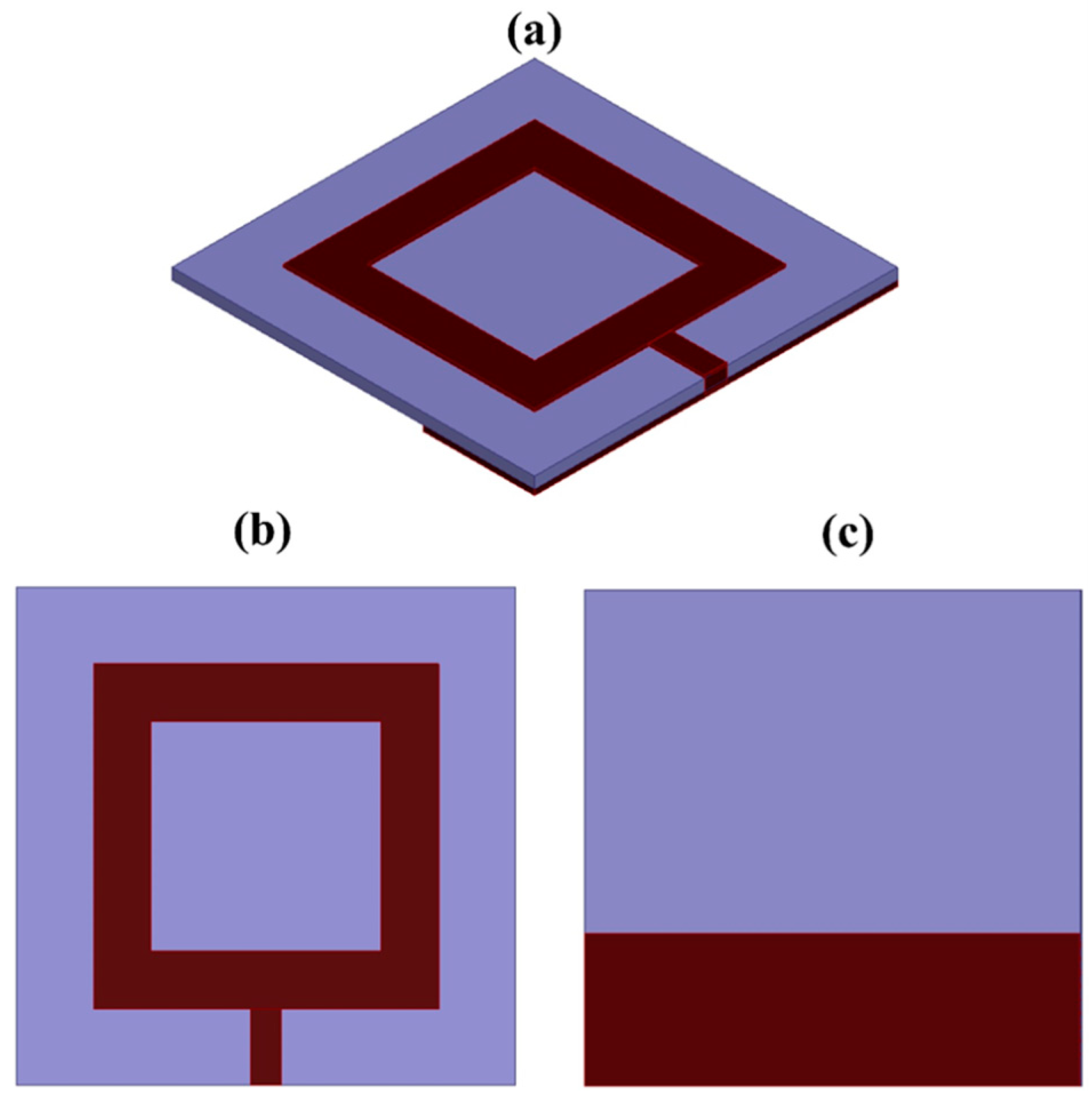
  • Optimization to O-shape fractal design: The research presents a novel approach by optimizing an antenna design to an O-shape fractal design from a square patch design. This change in design is a unique feature.
  • Operation in the THz band: The antenna is designed to operate in the THz (Terahertz) band, which is a relatively unexplored and cutting-edge frequency range. This is a novel application for antennas.
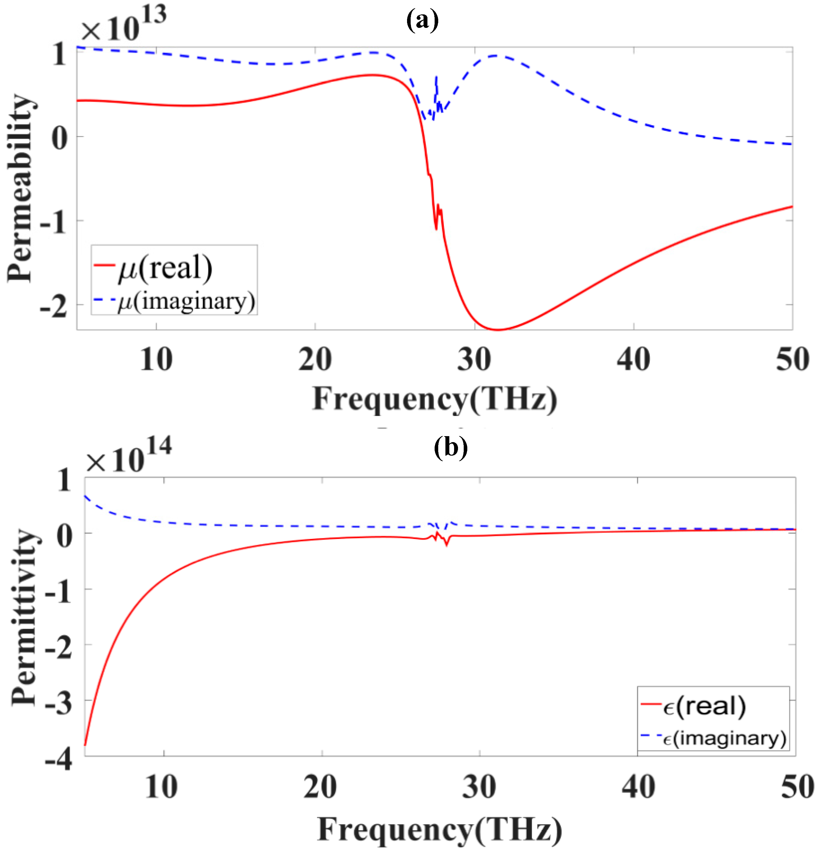
  • Metamaterial properties: The THz patch antenna is investigated for its metamaterial properties, indicating a focus on advanced materials, which is a novelty.
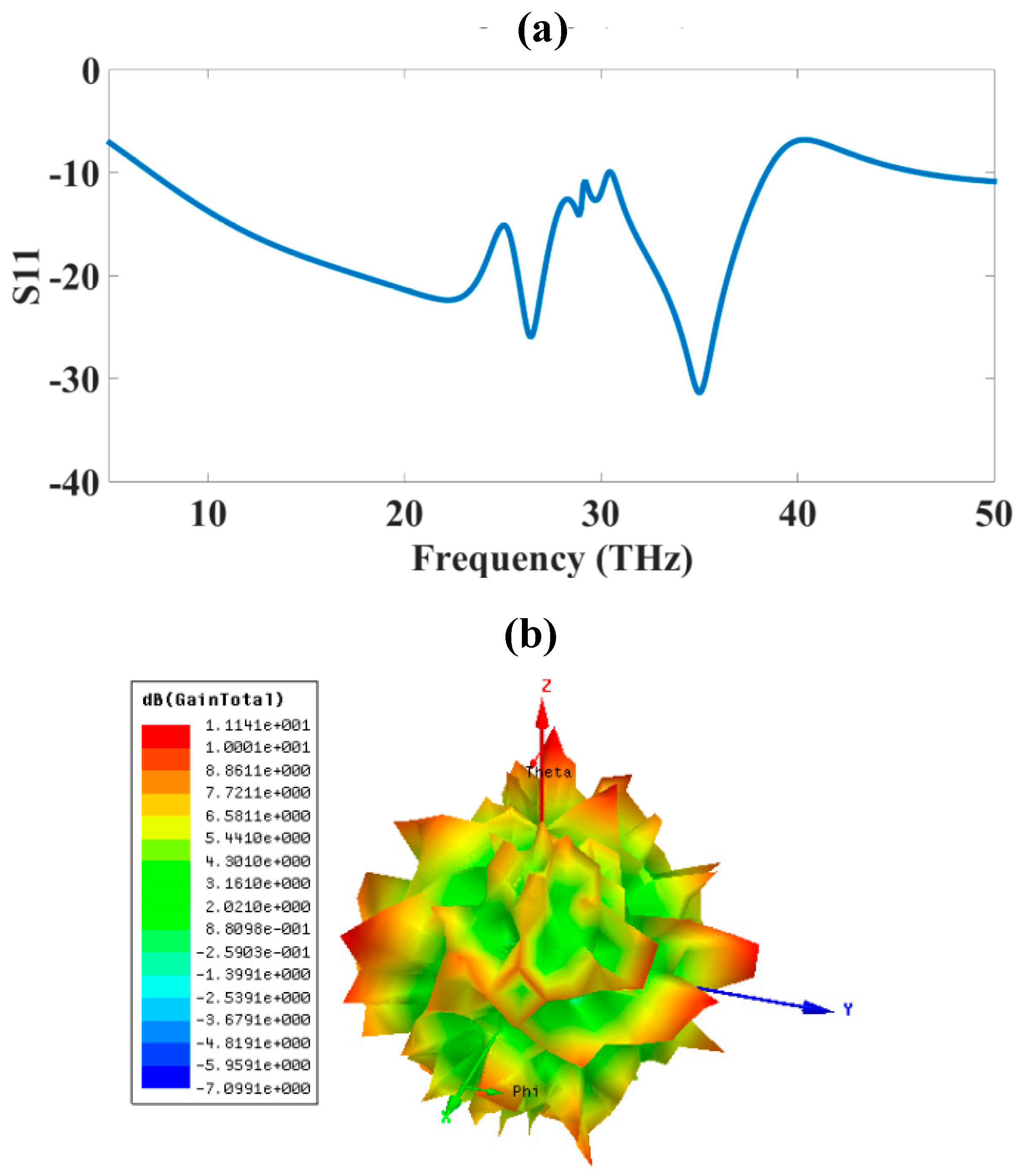
  • High bandwidth and gain: The optimized design achieves a very high bandwidth of 31.4 THz (138%) and the highest gain of 11.1 dBi. These performance metrics are noteworthy and represent a novel achievement.
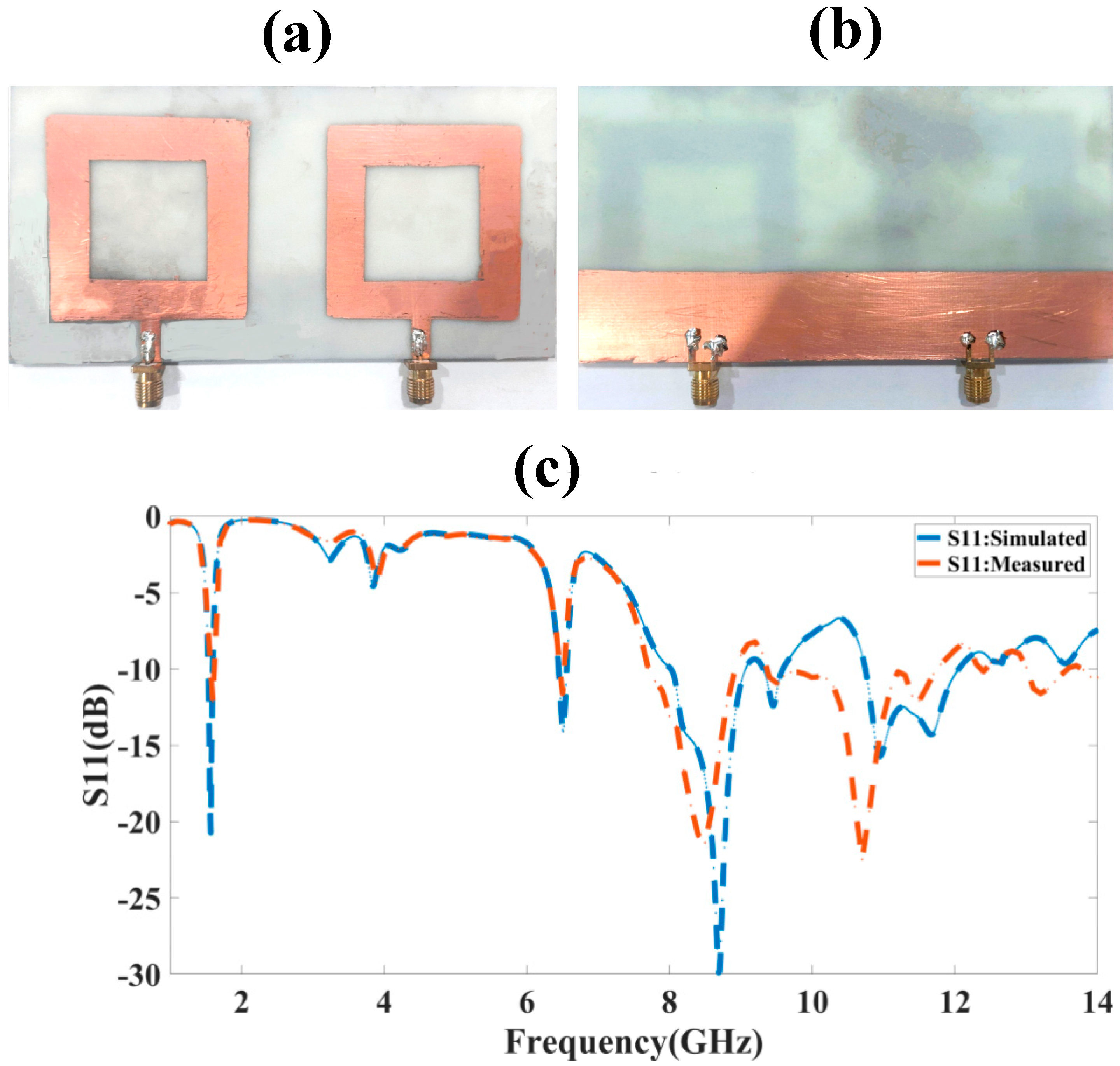
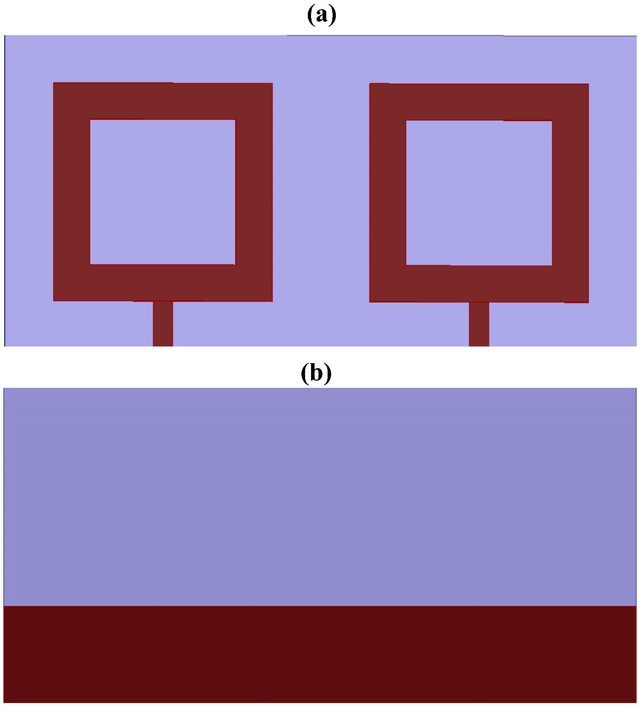
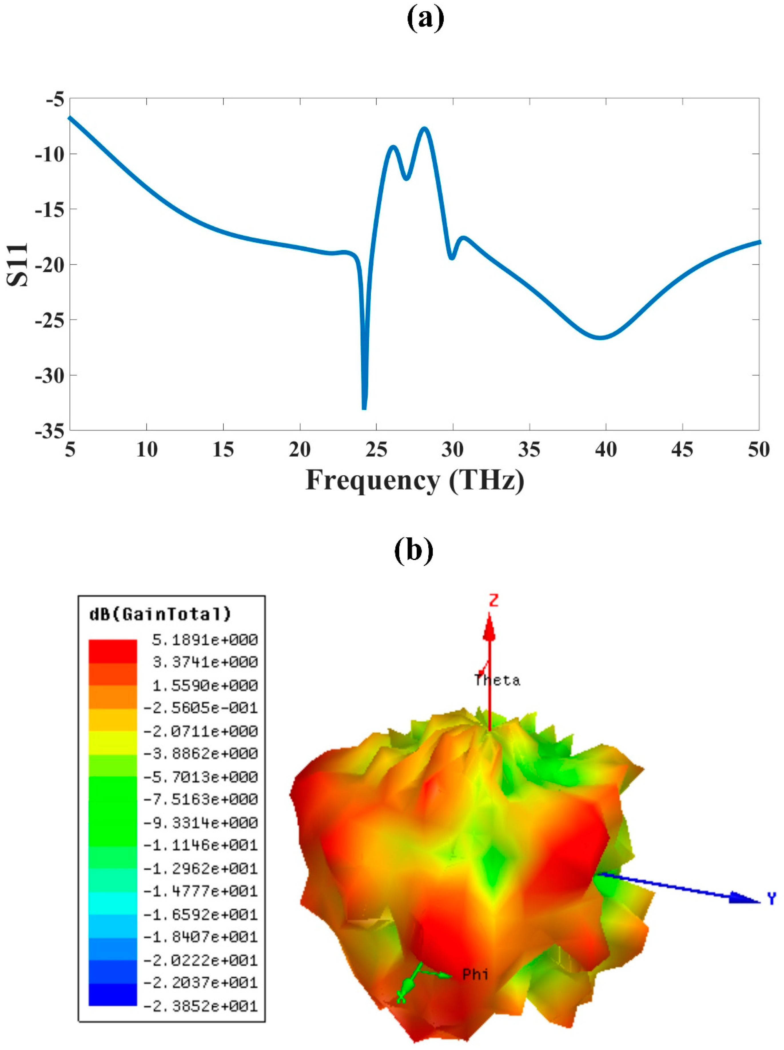
  • Two-element MIMO antenna design: The research explores a two-element MIMO antenna design using the O-shape patch, which provides a dual-band operation with unique bandwidths and gain values, showcasing a novel multi-element configuration.
  • Comparison with other designs: The comparison between the O-shape single-element fractal design, two-element fractal MIMO design, and other published designs helps highlight the uniqueness and novelty of the presented antenna design.
  • Application to 6G high-speed mobile communication devices: The manuscript suggests that the compact, broadband, and high-gain antenna design can be used for 6G high-speed mobile communication devices, implying a novel potential application.
The literature discussed so far shows that there is a need for an antenna that is compact in size which can be applicable for portable mobile devices for 6G applications. The antenna should also provide ultra-broadband and high gain features for high-speed communication and good coverage. So, the need for compact, ultra-broadband, and high gain antenna arises for 6G communications. We have proposed an antenna with a high gain, ultra-broadband response and a compact size, which are required for 6G communication antennas. We have designed a single-element antenna and a 2 × 2 MIMO antenna. The antenna performance is also analyzed for different physical parameter variations as well as for different element variations for the patch to achieve a compact design with good performance parameters. The antenna design, modeling, results, and conclusions are analyzed and presented in upcoming sections.

2. Single Element Design and Its Results

The design of a single-element patch antenna is presented in this section. The patch antenna is designed based on the standard patch equations available in Equations (1)–(4) [36]. The antenna is a square patch which is slotted with a small square patch from the middle which makes it an O-shape patch antenna. The slotted O-shape patch forms the metamaterial element in the patch antenna design. The slotted O-shape also forms the fractal metamaterial shape, which helps to improve the results compared to the simple patch design. The metamaterial fractal shape is also investigated for its metamaterial properties. The metamaterial element is also verified for its electrical permittivity and magnetic permeability in this section. The metamaterial equations presented in Equations (5)–(9) are used to obtain metamaterial properties [37]. The obtained O-shape patch is placed in two port waveguides to test the metamaterial properties. The results obtained by placing the values of reflectance (S11) and transmittance (S21) are presented in this section.
W = C 2 f r 2 ε r + 1
ε e f f = ε r + 1 2 + ε r 1 2 1 + 12 h w 0.5
Δ L h = 0.412 ( ε e f f + 0.3 ) w h + 0.264 ( ε e f f 0.258 ) w h + 0.8
L = 1 2 f r ε e f f μ 0 ε 0 2 Δ
z = ± ( 1 + S 11 ) 2 S 21 2 ( 1 S 11 ) 2 S 21 2
e i n k 0 d = S 21 1 S 11 z 1 z + 1
n = 1 k 0 d ln ( e i n k 0 d ) + 2 m π i ln ( e i n k 0 d )
ε = n z .
μ = n z
The design of the O-shape patch nanoantenna is presented in Figure 1. The size of the patch is very compact at 45 × 45 µm2. The substrate size is 65 × 65 µm2. The total antenna size is 65 × 65 × 2.9 µm2. The size is very compact and is essential for the nanoantenna designs and for accommodation in small portable devices. The different views are presented in Figure 1. The slot size taken out of the patch is 30 × 30 µm2 from the center of the patch, which makes the O-shape. The O-shape patch is fed with a microstrip line feed shown in the figure. The substrate is made up of a polyamide substrate material. The ground plane of the patch is defected by etching one part of the ground plane and the new defected ground plane is now 20 µm wide. The length of the ground plane is 65 µm. The etching of the ground plant and patch makes it more effective and achieves a better performance. The performance of the O-shape patch antenna in terms of its reflectance and gain is shown in Figure 2.
The design results for the S11 are presented in Figure 2a. If we consider the −10 dB cut-off for the antenna bandwidth then the bandwidth of this antenna is 31.4 THz. The bandwidth presented also shows that all the values between this bandwidth are less than −10 dB. The plot shows that there is one point where the plot shows the bandwidth near −10 dB but again it reduces further and the overall bandwidth for this band comes up to 31.4 THz, starting at 7 THz and ending at 38.4 THz, which is about 138% of the bandwidth; this is good for portable communication antennas. The gain of the single-element O-shape plasmonic nanoantenna is presented in Figure 2b. The highest gain of the O-shape plasmonic nanoantenna is about 11.1 dBi, as presented in the red color in the figure. The gain improvement in the design is because of the slot taken out of the simple patch antenna, which makes it an O-shape patch antenna.
The realization of the antenna’s structure is carried out in the millimeter scale and the performance in terms of return loss is compared among the simulated and measured results at the gigahertz frequency. The upper view is represented in Figure 3a and the bottom view is represented in Figure 3b. The proposed two-port MIMO antenna structure provides a multiband response. The first band is observed in the 6.451 GHz to 6.561 GHz range, the second band between 8.021 GHz and 9.061 GHz, the third band is observed between 9.321 GHz and 9.581 GHz, and the fourth band between 10.751 GHz and 12.051 GHz. The minimum return losses of all bands are, respectively, −14 dB at 6.51 GHz, −30 dB at 8.681 GHz, −12.43 dB at 9.451 GHz, and −15.73 dB at 10.951 GHz. The peak bandwidth of 1.3 GHz is observed in the fourth band. The healthy similarity among simulated and measured responses can be observed in Figure 3c. The physical realization of the same shaped structure in the micrometer scale for the THz span is also possible by choosing the proper fabrication methods.
The metamaterial properties are presented in Figure 4. The permittivity results, provide the behavior of the electric field and permeability, which give the behavior of the magnetic field. When both parameters show negative values, the metamaterial effect is achieved in the antenna. The metamaterial properties are essential to determining whether it is a metamaterial antenna. Here, we have investigated the properties by applying the S-parameter values of the two port systems in Equations (5)–(9). The O-shape patch is placed in between the two port waveguides and two port parameters are obtained, which are placed in the equations to obtain permittivity and permeability values. The values are presented in Figure 4. The permeability presents the amount of change in the magnetic field of the antenna and the current distribution effect shows the negative real permeability for the values around 25 THz onwards, which shows that it has negative behavior above 25 THz. The permittivity shows the negative real values near 25 THz only for a small range. Thus, the antenna shows double negative behavior around the 25 THz frequency. The red line solid curve in the figure shows real values while the blue dash curve shows the imaginary values. The negative values of the permittivity and permeability also create a negative refractive index. Thus, negative refraction is achieved in the material using this metamaterial design. The investigation of the metamaterial properties clearly shows that the created fractal metamaterial O-shape has metamaterial properties. The real and imaginary values of the plot clearly indicate the metamaterial behavior.

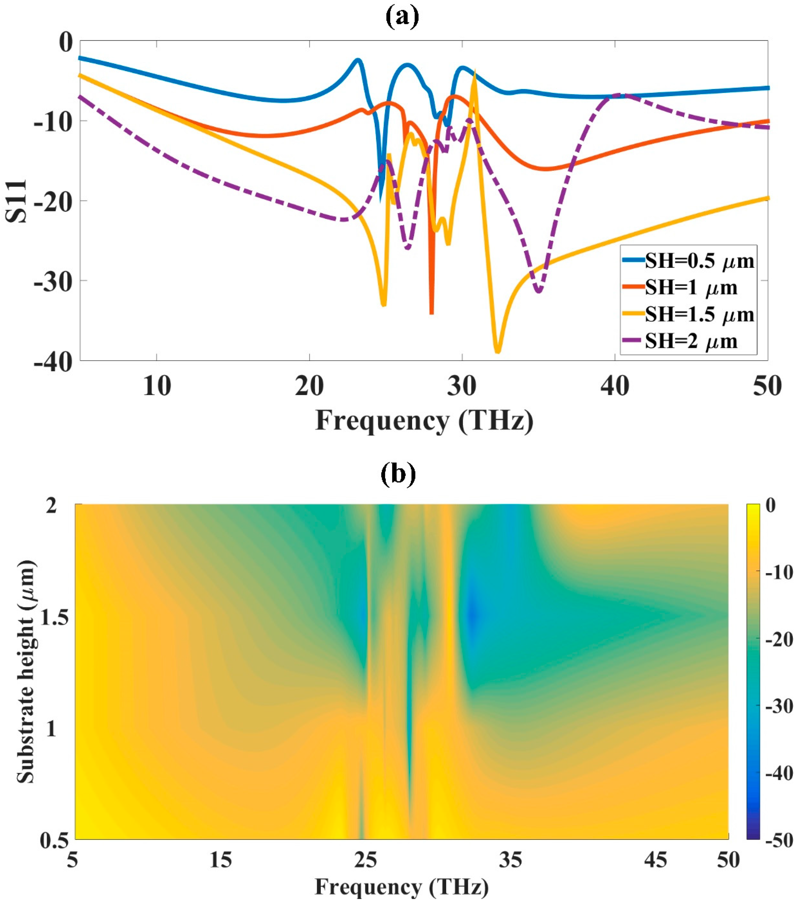
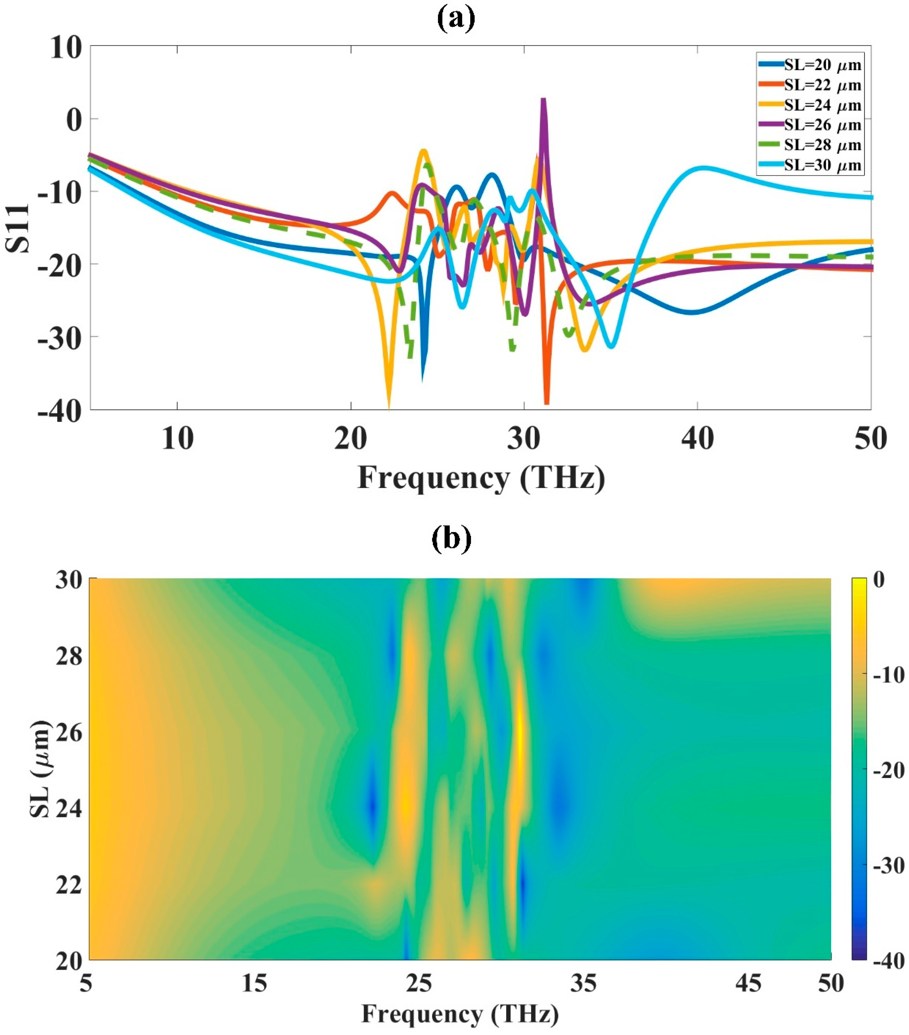
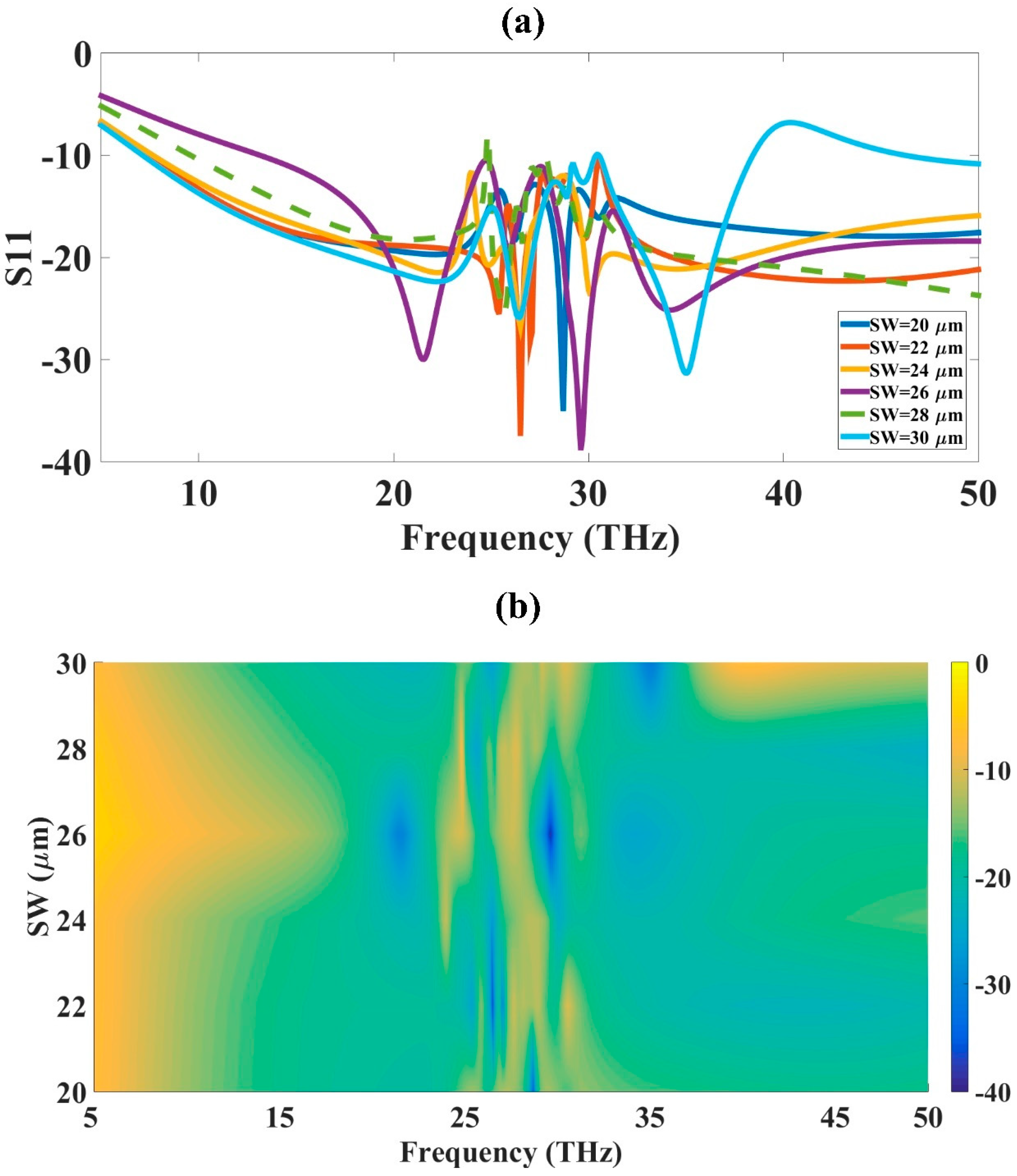
3. Parametric Variation for Optimization

Optimizations have two main types. The first is linear parametric optimization, which is applied to designs that behave linearly, and the second is nonlinear optimization, where the designs behave nonlinearly. The nonlinear parametric optimization is used when there is the dependence of one parameter on the other parameter, while the other parameters are kept the same and the behavior is nonlinear. We have also investigated the response for a different variation of the structural parameters and optimized those parameters to obtain the highest results. The response presented for this antenna design behaves nonlinearly and can also be applied to this design [38]. The O-shape antenna design presented in Figure 1 is varied for different physical parameters before the final values are set. The variation is kept for those parameters that affect the antenna performance more. One such parameter is substrate thickness. This parameter is important because the change in the thickness changes the inductance of the design and it changes the impedance and resonance of the antenna. The variation in this thickness helps in finding out the optimal performance of the design. The substrate height is varied from 0.5 to 2 µm and the results are presented in Figure 5. The results presented in the figure are shown in different colors and the one with the dashed line shows the best performance at a 2 µm thickness of the substrate material.
The optimization of the substrate height presented in the figure shows that, for an initial thickness of 0.5 µm, there is only one band available around the 3 THz bandwidth. The increase in the value of the substrate height increases the bandwidth further to 10 THz, but as we increase the thickness there is an increase in the inductance of the structure, which changes the resonance and that is why we have varied it to only 2 µm. The structure shows a 31.4 THz bandwidth for the 2 µm substrate height. The color plot in the figure shows that the blue color curve is more on the higher side of substrate thickness. The blue color shows high values and the yellow color shows low values.
The slot was inserted in the center of the square patch, which makes it an O-shape patch antenna. The slot length and width are also varied, and performance is observed for this variation and optimum values are selected. The variation in the slot length and its effect on the results are presented in Figure 6. The variation in the slot length changes the O-shape, which changes the results and also changes the metamaterial effect, which is introduced because of this variation in the design. The slot length variation is applied for 20 to 30 µm. As shown in the results for the slot length of 26 µm, the resonance changes and the values show that the position S11 values are not valid for the antenna design. The blue dash curve shows the 30 µm slot length, which has the highest bandwidth of 31.4 THz.
Similarly, slot width is also varied to observe its effect on the results and variation is applied for 20 to 30 µm. The reason for selecting this range is because the total size of the patch is 45 µm, so increasing the slot size further reduces the effective area of the patch. The results for slot width are presented in Figure 7. The initial width of 20 µm shows one band near 26 THz and its bandwidth is high and the color plot presented in Figure 7 shows it with a blue color. The blue color shows high values and the yellow shows low values. The increase in the slot width increases the results and this is shown in Figure 7. For the highest slot width, the results are higher compared to other values. The highest bandwidth of 31.4 THz is achieved for the highest width of 30 µm.

4. Two-Port MIMO Antenna Design and Results

The two-port MIMO antenna is designed by applying the two single-element O-shape antenna 20 µm apart as shown in Figure 8. The two-port antenna design is backed by a defected ground structure with a length of 130 µm and a width of 20 µm. The two elements are accommodated in 130 × 65 µm2. The design has a similar size in terms of width while the length is doubled compared to the design presented earlier with a single element. Thus, the area of the antenna is increased compared to the single element design but the results are improved in terms of bandwidth, as presented in Figure 9. The bandwidth of the antenna is improved, giving two bands with 18 THz and 21 THz bandwidth for the investigated range of 5 THz to 50 THz. The investigated range is the same as that given in the single-element design. The bandwidth is improved for the two-element MIMO antenna design. The two bands are presented in Figure 9a. The gain of this design is also investigated, which has a maximum value of 5.11 dBi. The design of the O-shape MIMO antenna is fed with two different port as shown in Figure 7.
The antenna performance of the two-element design has some gain in a few parameters while other parameters do not improve. Thus, both designs can be used based on the requirement of the device. When there is a compact design requirement, the design with single elements can serve better compared to the two-element design. If the design needs a multiband response, then the two-element design is better as it has two bands with good bandwidth. The single-element design also has a higher gain so can be applicable to higher gain requirements. The material used for the two-port MIMO antenna design is the same as that for the single-element design. There has been no variation in the materials, so the comparison of the two antenna design results shows information about the different important parameters.
The MIMO antenna with two elements shows more bands compared to the single-element design. The overall bandwidth of the MIMO antenna is higher compared to the single element if we consider both bands. The single-element design has a compact size compared to the MIMO antenna and the gain of the single-element design is higher compared to that of the two-port MIMO antenna design. The comparison of the two-port MIMO antenna with the single-element design and other published designs is presented in Table 2. The investigation is carried out for gain, bandwidth, and size of the design.

5. Conclusions

An optimized THz antenna design is presented that can operate for 6G high-speed wireless communication applications. The square-shaped patch antenna design is optimized by etching it with a square slot of 30 × 30 µm2. The slot length and width are optimized for 20 µm to 30 µm, and an optimized value of 30 µm is obtained. The optimization of substrate height is also carried out, which resulted in an optimized value of 2 µm. The optimized design is an O-shape patch design that has compact dimensions and a gain of 11.1 dBi with a bandwidth of 31.4 THz (138%). Further analysis is given for two two-element MIMO designs, created using two elements of the optimized O-shape patch design. The two-port MIMO antenna design shows a bandwidth of 18 THz (113%) and 21 THz (56%). The gain of this design is 5.18 dBi. The gain and size of a single element are better when compared to the two two-element MIMO antenna designs, but the bandwidth of the two-element MIMO antenna design is better if we consider both bands. A comparative analysis of both designs with other published designs is also investigated.

Author Contributions

Conceptualization, S.K.P. and A.B.; Methodology, S.K.P. and A.B.; Software, S.K.P. and A.B.; Writing—original draft, S.K.P. and A.B.; Writing—review & editing, S.K.P. and A.B. All authors have read and agreed to the published version of the manuscript.

Funding

The authors extend their appreciation to the Deanship for Research & Innovation, Ministry of Education in Saudi Arabia for funding this research work through the project number: IFP22UQU4260426DSR172.

Institutional Review Board Statement

Not applicable.

Informed Consent Statement

Not applicable.

Data Availability Statement

Data are contained within the article.

Acknowledgments

The authors extend their appreciation to the Deanship for Research & Innovation, Ministry of Education in Saudi Arabia for funding this research work through the project number: IFP22UQU4260426DSR172.

Conflicts of Interest

The authors declare no conflict of interest.

References

  1. Elbir, A.M.; Mishra, K.V.; Chatzinotas, S. Terahertz-Band Joint Ultra-Massive MIMO Radar-Communications: Model-Based and Model-Free Hybrid Beamforming. IEEE J. Sel. Top. Signal Process. 2021, 15, 1468–1483. [Google Scholar] [CrossRef]
  2. Sharma, M.K.; Sharma, A. Compact size easily extendable self isolated multi-port multi-band antenna for future 5G high band and sub-THz band applications. Opt. Quantum Electron. 2023, 55, 146. [Google Scholar] [CrossRef]
  3. Kim, Y.; Pham, D.A.; Phon, R.; Lim, S. Lightweight 3D-Printed Fractal Gradient-Index Lens Antenna with Stable Gain Performance. Fractal Fract. 2022, 6, 551. [Google Scholar] [CrossRef]
  4. Gupta, A.K.; Mohanta, H.C.; Chowdary, P.S.R.; Krishna, M.V.; Mohamed, H.G. Design and Analysis of Fractal-Shaped High-Impedance Surface Unit Cell Characteristics. Fractal Fract. 2023, 7, 472. [Google Scholar] [CrossRef]
  5. Xu, H.X.; Wang, G.M.; Zhang, C.X. Fractal-shaped metamaterials and applications to enhanced-performance devices exhibiting high selectivity. Int. J. Antennas Propag. 2012, 2012, 515167. [Google Scholar] [CrossRef]
  6. Bowen, P.T.; Baron, A.; Smith, D.R. Theory of patch-antenna metamaterial perfect absorbers. Phys. Rev. A 2016, 93, 063849. [Google Scholar] [CrossRef]
  7. Slimi, M.; Jmai, B.; Dinis, H.; Gharsallah, A.; Mendes, P.M. Metamaterial Vivaldi Antenna Array for Breast Cancer Detection. Sensors 2022, 22, 3945. [Google Scholar] [CrossRef]
  8. Portosi, V.; Loconsole, A.M.; Prudenzano, F. A split ring resonator-based metamaterial for microwave impedance matching with biological tissue. Appl. Sci. 2020, 10, 6740. [Google Scholar] [CrossRef]
  9. Loukil, M.H.; Sarieddeen, H.; Alouini, M.S.; Al-Naffouri, T.Y. Terahertz-Band MIMO Systems: Adaptive Transmission and Blind Parameter Estimation. IEEE Commun. Lett. 2021, 25, 641–645. [Google Scholar] [CrossRef]
  10. Gupta, A.; Chaudhary, R.K. A Compact Pentagonal Ring CPW-Fed Zeroth Order Resonating Antenna with Gain Enhancement. Frequenz 2017, 71, 261–266. [Google Scholar] [CrossRef]
  11. Khan, M.A.K.; Ullah, M.I.; Kabir, R.; Alim, M.A. High-Performance Graphene Patch Antenna with Superstrate Cover for Terahertz Band Application. Plasmonics 2020, 15, 1719–1727. [Google Scholar] [CrossRef]
  12. Benkhallouk, K.; Bendaoudi, A.; Berka, M.; Mahdjoub, Z. Enhanced radiation characteristics of regular dodecagon split ring resonator (D-SRR)-based microstrip patch antenna employing dielectric superstrate for THz applications. J. Eng. Appl. Sci. 2022, 69, 1–16. [Google Scholar] [CrossRef]
  13. Keshwala, U. Microstrip line fed sinusoidal tapered square shaped MIMO antenna for THz applications. Optik 2021, 247, 167905. [Google Scholar] [CrossRef]
  14. Krishna, C.M.; Das, S.; Nella, A.; Lakrit, S.; Madhav, B.T.P. A Micro-Sized Rhombus-Shaped THz Antenna for High-Speed Short-Range Wireless Communication Applications. Plasmonics 2021, 16, 2167–2177. [Google Scholar] [CrossRef]
  15. Das, S.; Lakrit, S.; Krishna, C.M.; Varakumari, S.; Mohammed, B.; Ahmed, F. A novel flower petal-shaped super wideband (439.36–557.59 THz) optical nano-antenna for terahertz (THz) wireless communication applications. Opt. Quantum Electron. 2023, 55, 516. [Google Scholar] [CrossRef]
  16. Shihzad, W.; Ullah, S.; Ahmad, A.; Abbasi, N.A.; Choi, D.Y. Design and Analysis of Dual-Band High-Gain THz Antenna Array for THz Space Applications. Appl. Sci. 2022, 12, 9231. [Google Scholar] [CrossRef]
  17. Jia, Y.; Xu, P.; Guo, X. MIMO system capacity based on different numbers of antennas. Results Eng. 2022, 15, 100577. [Google Scholar] [CrossRef]
  18. Abdelrahman, A.; Erchiqui, F.; Nedil, M. Studying and evaluation physical characteristic of composite substrate chip and, its application. Results Eng. 2022, 15, 100533. [Google Scholar] [CrossRef]
  19. Sumathi, K.; Lavadiya, S.; Yin, P.Z.; Parmar, J.; Patel, S.K. High gain multiband and frequency reconfigurable metamaterial superstrate microstrip patch antenna for C/X/Ku-band wireless network applications. Wirel. Netw. 2021, 27, 2131–2146. [Google Scholar] [CrossRef]
  20. Keerthi, R.S.; Dhabliya, D.; Elangovan, P.; Borodin, K.; Parmar, J.; Patel, S.K. Tunable high-gain and multiband microstrip antenna based on liquid/copper split-ring resonator superstrates for C/X band communication. Phys. B Condens. Matter 2021, 618, 413203. [Google Scholar] [CrossRef]
  21. Raj, U.; Sharma, M.K.; Singh, V.; Javed, S.; Sharma, A. Easily extendable four port MIMO antenna with improved isolation and wide bandwidth for THz applications. Optik 2021, 247, 167910. [Google Scholar] [CrossRef]
  22. Pant, R.; Malviya, L. THz antennas design, developments, challenges, and applications: A review. Int. J. Commun. Syst. 2023, 36, e5474. [Google Scholar] [CrossRef]
  23. Hajiyat, Z.R.M.; Ismail, A.; Sali, A.; Hamidon, M.N. Antenna in 6G wireless communication system: Specifications, challenges, and research directions. Optik 2021, 231, 166415. [Google Scholar] [CrossRef]
  24. Duan, B.Y. Evolution and innovation of antenna systems for beyond 5G and 6G. Front. Inf. Technol. Electron. Eng. 2020, 21, 1–3. [Google Scholar] [CrossRef]
  25. Khaleel, S.A.; Hamad, E.K.I.; Parchin, N.O.; Saleh, M.B. MTM-Inspired Graphene-Based THz MIMO Antenna Configurations Using Characteristic Mode Analysis for 6G/IoT Applications. Electronics 2022, 11, 2152. [Google Scholar] [CrossRef]
  26. Saxena, G.; Chintakindi, S.; Kasim, M.A.; Maduri, P.K.; Awasthi, Y.K.; Kumar, S.; Kansal, S.; Jain, R.; Sharma, M.K. Metasurface inspired wideband high isolation THz MIMO antenna for nano communication including 6G applications and liquid sensors. Nano Commun. Netw. 2022, 34, 100421. [Google Scholar] [CrossRef]
  27. Saxena, G.; Awasthi, Y.K.; Jain, P. High Isolation and High Gain Super-Wideband (0.33-10 THz) MIMO Antenna for THz Applications. Optik 2020, 223, 165335. [Google Scholar] [CrossRef]
  28. Singhal, S. Tetradecagonal ring shaped terahertz superwideband MIMO antenna. Optik 2020, 208, 164066. [Google Scholar] [CrossRef]
  29. Rubani, Q.; Gupta, S.H.; Rajawat, A. A compact MIMO antenna for WBAN operating at Terahertz frequency. Optik 2020, 207, 164447. [Google Scholar] [CrossRef]
  30. Das, S.; Mitra, D.; Chaudhuri, S.R.B. Fractal loaded planar Super Wide Band four element MIMO antenna for THz applications. Nano Commun. Netw. 2021, 30, 100374. [Google Scholar] [CrossRef]
  31. Babu, K.V.; Das, S.; Varshney, G.; Sree, G.N.J.; Madhav, B.T.P. A micro-scaled graphene-based tree-shaped wideband printed MIMO antenna for terahertz applications. J. Comput. Electron. 2022, 21, 289–303. [Google Scholar] [CrossRef]
  32. Siddiqui, M.U.A.; Qamar, F.; Kazmi, S.H.A.; Hassan, R.; Arfeen, A.; Nguyen, Q.N. A Study on Multi-Antenna and Pertinent Technologies with AI/ML Approaches for B5G/6G Networks. Electronics 2022, 12, 189. [Google Scholar] [CrossRef]
  33. Mahmood, M.R.; Matin, M.A.; Sarigiannidis, P.; Goudos, S.K. A Comprehensive Review on Artificial Intelligence/Machine Learning Algorithms for Empowering the Future IoT Toward 6G Era. IEEE Access 2022, 10, 87535–87562. [Google Scholar] [CrossRef]
  34. Nguyen, D.C.; Ding, M.; Pathirana, P.N.; Seneviratne, A.; Li, J.; Niyato, D.; Poor, H.V. 6G Internet of Things: A Comprehensive Survey. IEEE Internet Things J. 2022, 9, 359–383. [Google Scholar] [CrossRef]
  35. El-Kenawy, E.S.M.; Abutarboush, H.F.; Mohamed, A.W.; Ibrahim, A. Advance Artificial Intelligence Technique for Designing Double T-Shaped Monopole Antenna. Comput. Mater. Contin. 2021, 69, 2983–2995. [Google Scholar] [CrossRef]
  36. Nguyen, T.K.; Patel, S.K.; Lavadiya, S.; Parmar, J.; Bui, C.D. Design and fabrication of multiband reconfigurable copper and liquid multiple complementary split-ring resonator based patch antenna. Waves Random Complex Media 2022, 32, 1–24. [Google Scholar] [CrossRef]
  37. Armghan, A.; Alsharari, M.; Aliqab, K.; Alsalman, O.; Parmar, J.; Patel, S.K. Graphene Twistronics: Tuning the Absorption Spectrum and Achieving Metamaterial Properties. Mathematics 2023, 11, 1579. [Google Scholar] [CrossRef]
  38. Alsharari, M.; Armghan, A.; Aliqab, K. Numerical Analysis and Parametric Optimization of T-Shaped Symmetrical Metasurface with Broad Bandwidth for Solar Absorber Application Based on Graphene Material. Mathematics 2023, 11, 971. [Google Scholar] [CrossRef]
  39. Benlakehal, M.E.; Hocini, A.; Khedrouche, D.; Temmar, M.N.E.; Denidni, T.A. Design and analysis of MIMO system for THz communication using terahertz patch antenna array based on photonic crystals with graphene. Opt. Quantum Electron. 2022, 54, 693. [Google Scholar] [CrossRef]
  40. Muthukrishnan, K.; Kamruzzaman, M.M.; Lavadiya, S.; Sorathiya, V. Superlative split ring resonator shaped ultrawideband and high gain 1×2 MIMO antenna for Terahertz communication. Nano Commun. Netw. 2023, 36, 100437. [Google Scholar] [CrossRef]
  41. Singhal, S. Elliptical ring terahertz fractal antenna. Optik 2019, 194, 163129. [Google Scholar] [CrossRef]
  42. Maurya, N.K.; Kumari, S.; Pareek, P.; Singh, L. Graphene-based frequency agile isolation enhancement mechanism for MIMO antenna in terahertz regime. Nano Commun. Netw. 2023, 35, 100436. [Google Scholar] [CrossRef]
  43. Zhang, B.; Jornet, J.M.; Akyildiz, I.F.; Wu, Z.P. Mutual coupling reduction for ultra-dense multi-band plasmonic nano-antenna arrays using graphene-based frequency selective surface. IEEE Access 2019, 7, 33214–33225. [Google Scholar] [CrossRef]
  44. Younssi, M.; Jaoujal, A.; Diallo, Y.; El Moussaoui, A.; Aknin, N. Study of a Microstrip Antenna with and Without Superstrate for Terahertz Frequency. Int. J. Innov. Appl. Stud. 2013, 2, 369–371. [Google Scholar]
  45. Babu, K.V.; Das, S.; Sree, G.N.J.; Madhav, B.T.P.; Patel, S.K.K.; Parmar, J. Design and optimization of micro-sized wideband fractal MIMO antenna based on characteristic analysis of graphene for terahertz applications. Opt. Quantum Electron. 2022, 54, 281. [Google Scholar] [CrossRef]
  46. Vettikalladi, H.; Sethi, W.T.; Abas, A.F.B.; Ko, W.; Alkanhal, M.A.; Himdi, M. Sub-THz Antenna for High-Speed Wireless Communication Systems. Int. J. Antennas Propag. 2019, 2019, 9573647. [Google Scholar] [CrossRef]
  47. Kushwaha, R.K.; Karuppanan, P.; Malviya, L.D. Design and analysis of novel microstrip patch antenna on photonic crystal in THz. Phys. B Condens. Matter 2018, 545, 107–112. [Google Scholar] [CrossRef]
Figure 1. O-shape patch antenna design with its different views (a) 3D (b) top (c) back.
Fractalfract 08 00017 g001
Figure 2. Results of the O-shape patch antenna (a) S11 (b) Gain. The highest bandwidth of 31.4 THz (138%) and the highest gain of 11.1 dBi is achieved.
Fractalfract 08 00017 g002
Figure 3. The physical realization of two-port MIMO antenna structure at mm scale. (a) Upper view. (b) Bottom view. (c) The comparison among simulated and measured responses. The response provides a peak bandwidth of 1.3 GHz and a minimum return loss of −30 dB.
Fractalfract 08 00017 g003
Figure 4. O-shape patch antenna metamaterial properties: (a) Permeability; (b) Permittivity.
Fractalfract 08 00017 g004
Figure 5. Substrate height change and its effect on S11. (a) Line plot. (b) Contour Plot.
Fractalfract 08 00017 g005
Figure 6. Slot length change and its effect on S11. (a) Line plot. (b) Contour Plot.
Fractalfract 08 00017 g006
Figure 7. Slot width change and its effect on S11. (a) Line plot. (b) Contour Plot.
Fractalfract 08 00017 g007
Figure 8. O-shape two port MIMO antenna design with its different views: (a) top; (b) back.
Fractalfract 08 00017 g008
Figure 9. Results of the O-shape two-port MIMO antenna: (a) S11; (b) gain. Two bands are achieved with the bandwidth of 18 THz (112%) and 21 THz (53%) and the highest gain of 5.18 dBi is achieved.
Fractalfract 08 00017 g009
Table 1. Literature survey related to THz band operated MIMO antenna structures.
Ref.BandStructure TypeApplication
[25]1 THz to 10 THzMTM-inspired, graphene-based THz MIMO antenna.6G/IoT
[26]0.1 THz to 2 THzMetasurface-inspiredNanocommunication
[27]0.1 THz to 10 THzElliptical-shaped microstrip feedHealth care and astronomical radiometric
[28]0.25 THz to 15.4 THzTetradecagonal ring-shapedExplosive detection, weapon detection
[29]8.5 THz to 9 THzRectangular-shaped four ArrayWBAN
[21]2 THz to 10 THzCircular monopole antennaHMX, detection of biotin and WBAN
[30]0.1 THz to 10 THzFractal-loaded planarB5G technology
[31]0.1 THz to 1 THzTree-shaped micro-scaled graphene antennaSensing and security scanning, biomedical imaging
Table 2. Comparison of size, gain, bandwidth, and isolation.
DesignSize of Antenna (µm2)Bandwidth
(THz)
Gain (dB)
[39]360 × 2200.611.8
[40]60 × 406.994.635
[41]800 × 60099.5
[27]1000 × 14009.619
[25]130 × 850.67.23
[27]1000 × 14009.6719
[42]300 × 2100.833.99
[43]13 × 2618.181.5
[30]125 × 1259.3-
[44]2000 × 10007610.43
[28]800 × 117014.8-
[45]600 × 30072.725.49
[46]822 × 2800.11613.6
[47]800 × 6005.717.934
O-shape patch antenna single element design65 × 6531.411.1
O-shape two port MIMO antenna design130 × 6518.215.18
Disclaimer/Publisher’s Note: The statements, opinions and data contained in all publications are solely those of the individual author(s) and contributor(s) and not of MDPI and/or the editor(s). MDPI and/or the editor(s) disclaim responsibility for any injury to people or property resulting from any ideas, methods, instructions or products referred to in the content.

