Article

Fractional-Order Impedance Control for Robot Manipulator

1
School of Mechanical Science and Engineering, Huazhong University of Science and Technology, Wuhan 430074, China
2
School of Electrical Engineering, Zhengzhou University, Zhengzhou 450001, China
*
Author to whom correspondence should be addressed.
Fractal Fract. 2022, 6(11), 684; https://doi.org/10.3390/fractalfract6110684
Submission received: 6 October 2022 / Revised: 2 November 2022 / Accepted: 8 November 2022 / Published: 18 November 2022
(This article belongs to the Special Issue Applications of Fractional-Order Calculus in Robotics)

Abstract

:
Impedance control is an important method in robot–environment interaction. In traditional impedance control, the damping force is regarded as a linear viscoelastic model, which limits the description of the dynamic model of the impedance system to a certain extent. For the robot manipulator, the optimal impedance parameters of the impedance controller are the key to improve the performance. In this paper, the damping force is described more accurately by fractional calculus than the traditional viscoelastic model, and a fractional-order impedance controller for the robot manipulator is proposed. A practical and systematic tuning procedure based on the frequency design method is developed for the proposed fractional-order impedance controller. The fairness of comparison between the fractional-order impedance controller and the integer-order impedance controller is addressed under the same specifications. Fair comparisons of the two controllers via the simulation and experiment tests show that, in the step response, the fractional-order impedance controller has a better integral time square error (ITSE) result, smaller overshoot and less settling time than the integer-order impedance controller. In terms of anti-disturbance, the fractional-order impedance controller can achieve stability with less recovering time and better ITSE index than integer order impedance controller.

1. Introduction

Robot manipulators have been playing an important role in industry, medical treatment and service industries. The manipulator is closely related to the environment in most working circumstances, which puts forward higher and higher requirements for the dynamic interaction between the robot manipulator and the environment [1,2,3]. The single trajectory control method may cause too much interaction force and result in damage, or the force may be too small to complete the task [4,5]. In order to expand the application range of robot manipulator and improve the system performance, controlling the contact force between the robot manipulator and the environment has become one of its hot research areas [6,7]. Active compliance control is one of the main ways to realize the force control, which adjusts the interaction force depending on the force feedback information from the joint or the force sensor installed at the end of the robot manipulator. The impedance control algorithm is a general strategy for the robot manipulator to realize active compliance control [8] which adopts the structure of inner loop position control and outer loop force control (also called admittance control) [9]. A user-defined dynamic relationship between the reference trajectory of the end effector and the interaction contact force can be built by the impedance control model.
Robot–environment interaction in an uncertain environment brings challenges to impedance control, such as cell injection, rehabilitation applications and complex workpiece curved surface processing. It is difficult to obtain the performance of accurate force tracking and the system robustness due to various unknown features. In an impedance control framework, choosing proper impedance parameters is the key to realize the desired impedance dynamics and guarantee the stability [10,11,12]. Otherwise, the compliance of robot–environment interaction would be severely affected. Accordingly, conventional impedance may not be suitable for these applications, and large errors of position and force might be produced [13].
Intelligent and advanced algorithms have been proposed to improve the performance of impedance controller in a complex uncertain environment. The impedance parameters matching the interaction environment properly are generated to cope with the uncertain environment. Zhang et al. [14] presented a variable impedance method to acquire the impedance parameters in real time, using the offline-trained fuzzy neural network system. In [15], the natural gradient actor-critic reinforcement learning algorithm was proposed to optimize the impedance parameters online. However, none of these works addresses the issue of sampling efficiency. A huge amount of training data is required in the learning methods, which is infeasible for the physical interacting system. Dong et al. [16] proposed a speed-based variable impedance adaptive interaction control method, and the damping parameter of the impedance controller was adaptively adjusted according to the interactive force-tracking error. In [12], an adaptive variable impedance control method was applied to track the desired dynamic force and compensate for uncertainties in the environment. However, the overshoot of the contact force, and the trade-off between force-tracking accuracy and system robustness were not addressed.
The traditional impedance control model is equivalent to a mass-spring-damper system, and the damping force is usually described by a linear viscoelastic model. However, the description accuracy of damping force is limited by the traditional linear model [17,18], which could affect the performance of the controller to a certain extent. Fractional calculus theory, as the extension of integer calculus, can describe physical objects more accurately [19,20]. Fractional-order control has been proven to achieve outstanding tracking performance and robustness [21,22]. Reference [23] used a fractional-order derivative to describe the damping force in the visco-elastic-dampers, which was more accurate and even required fewer parameters in comparison with other models. Fractional calculus provided flexibility in designing appropriate visco-elastic-dampers with a large variety of practicable values for parameters [23]. Wang et al. [24] extended the classical skyhook damping control strategy to the fractional-order one. A fractional-order skyhook damping control design method for full-car suspension was given, which obtained a more ideal control effect over the classical control method. The impedance model for the uncertain environment with nonlinear factors is a typical fractional-order object [9]. In this paper, fractional calculus theory is applied to optimize the performance of impedance control. The damping force in the impedance model is described more accurately using the fractional-order derivative than the traditional integer-order one. Based on the fractional-order damping force model, the traditional integer-order impedance (IO-impedance) control is extended to the fractional-order impedance (FO-impedance) control, which is applied to the compliance control of the robot manipulator. A fair comparison between IO-impedance control and FO-impedance control is addressed under the same design specifications. The simulation and experimental test show that the proposed FO-impedance controller outperforms the IO-impedance controller.
The main contributions of this paper include the following: (1) A FO-impedance controller for robot manipulator is proposed based on a proposed fractional order damping force model. (2) A systematic tuning method for the FO-impedance controller design is proposed with detailed procedure. The designed control system can meet the user given frequency domain specifications. (3) The simulation and experimental demonstration on the robot manipulator system are presented to verify the feasibility and advantages of the proposed FO-impedance controller compared with the optimal IO-impedance controller.
The remaining of this paper is organized as follows: Section 2 describes the impedance model and the FO-impedance controller optimal design method; the simulation illustration and experimental verification are shown in Section 3 and Section 4, respectively. The step response and anti-disturbance robustness performance of FO-impedance controller is studied and compared with the IO-impedance controller. The conclusion is given in Section 5.

2. FO-Impedance Controller Design

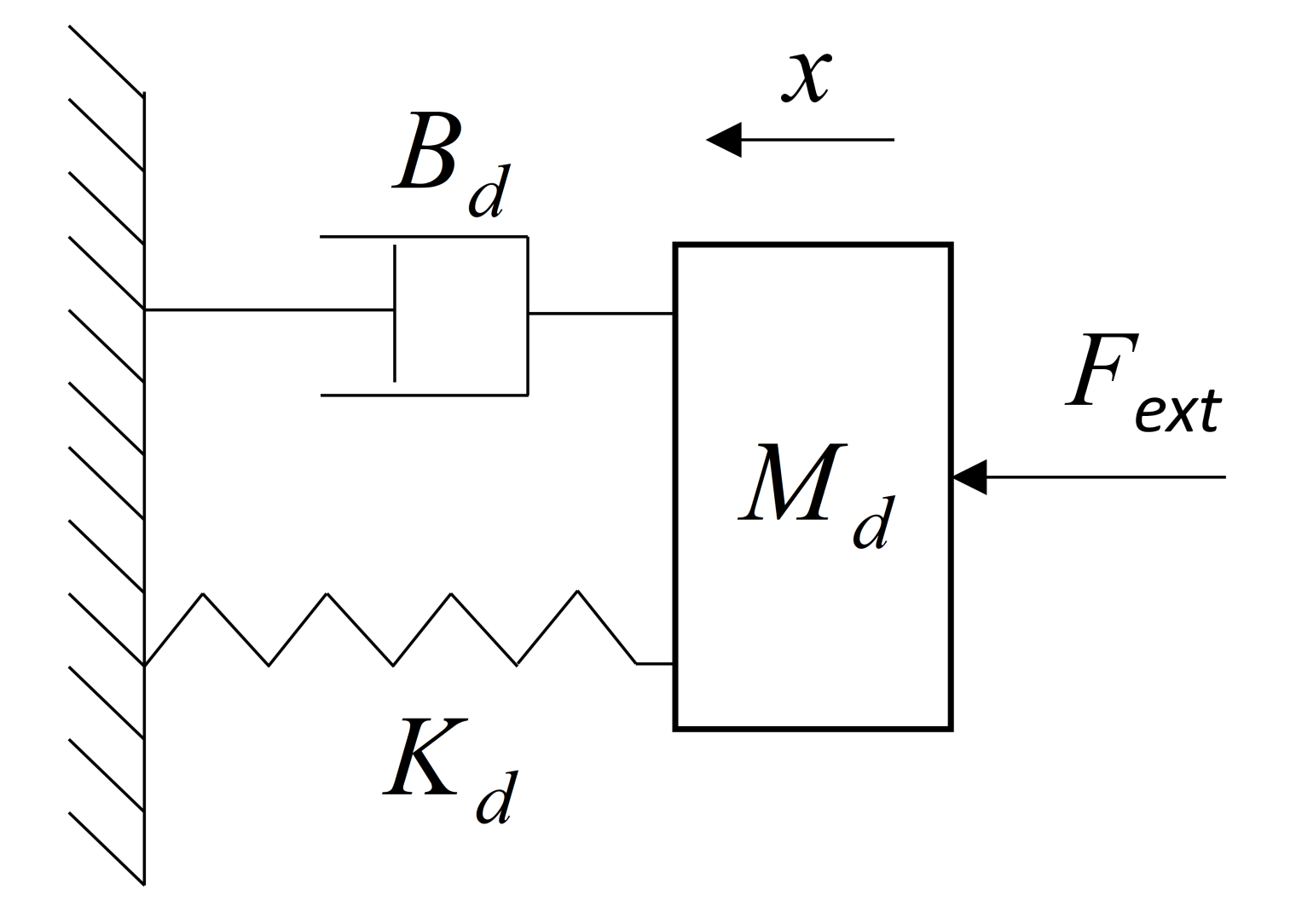
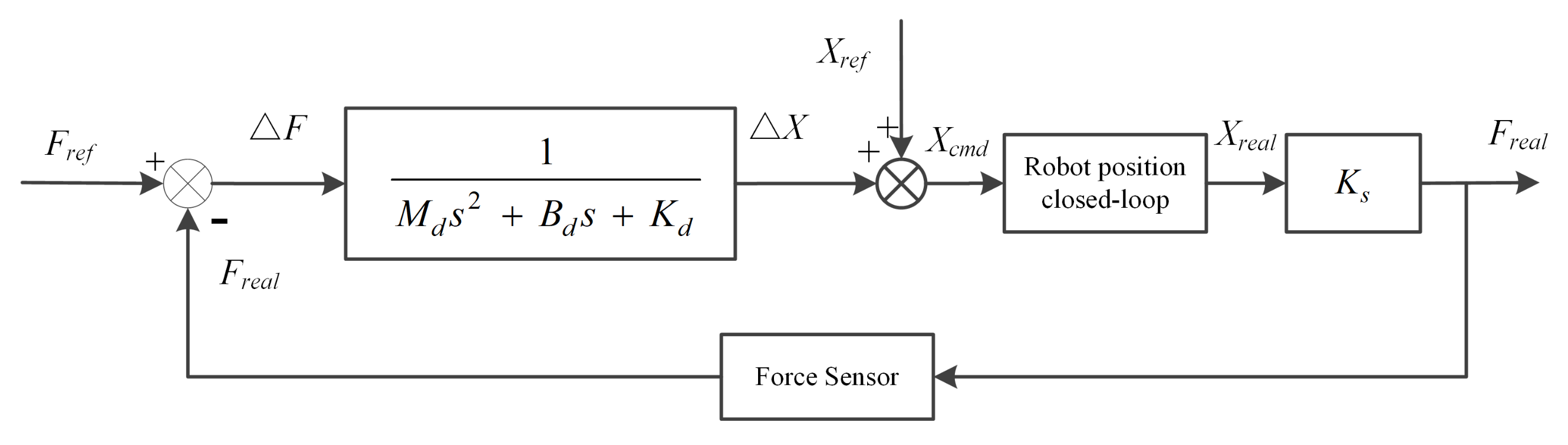
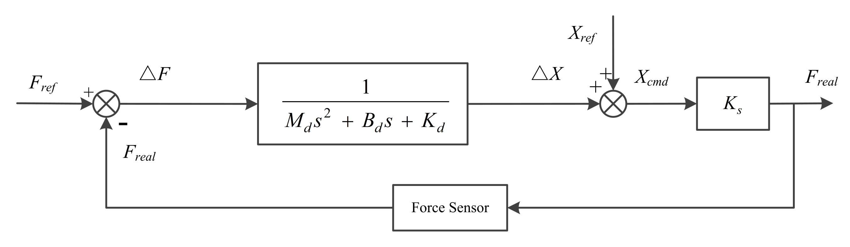
2.1. Impedance Control Methodology

The dynamic model of the robot manipulator impedance control mechanical system can be described as a mass-spring-damper system. The structure is shown in Figure 1, and the system dynamic equation is as follows:
M d x ¨ ( t ) + B d x ˙ ( t ) + K d x ( t ) = F ext ,
where x is the position, M d is the mass, B d is the damping, K d is the stiffness, and F ext is the contact force between the robot manipulator and the external environment.
According to Equation (1), one can get,
X ( s ) F ( s ) = 1 M d s 2 + B d s + K d .
For impedance control, the control system adopts position control as the inner loop and force control as the outer loop. For the robot manipulator, a force sensor is usually installed at the end of the robot manipulator to sense its contact force with the environment. Through the impedance control algorithm, the position information which needs to be corrected is generated according to the force error and input into the inner loop of position control, and then the contact force with the environment is adjusted.
The robot manipulator impedance-control-system block diagram is shown in Figure 2. The reference contact force between the end of the robot manipulator and the environment is set as F ref . The real contact force F real between the robot manipulator and the external environment is collected by the force sensor. Δ F is the difference between the real contact force and the reference contact force. The position variation Δ X of the robot manipulator end effector is calculated according to the impedance-control algorithm. Then the position control command X cmd is obtained as the target of the position control loop with position reference X ref and position variation Δ X . X real is the actual position of the robot manipulator end effector. K s is the external environmental stiffness in contact with the end of the robot manipulator.
The reference contact force F ref as the system input and the actual contact force F real as the system output are presented in Figure 3. The closed loop of the robot position control is replaced as 1 due to the high control bandwidth and high tracking performance of the robot manipulator position servo control system.
The open-loop transfer function of the feedback control system in Figure 3 can be expressed as,
G 0 ( s ) = K s M d s 2 + B d s + K d .
The closed-loop transfer function is,
G 1 ( s ) = K s M d s 2 + B d s + K d + K s .

2.2. Controllers Design

In this section, the methodologies of the IO-impedance controller and FO-impedance controller design are presented, respectively. In the position-based impedance control, virtual stiffness can lead to steady-state force-tracking errors [9,25]. Many control strategies have been proposed to attenuate the force tracking error [25,26,27]. Canceling the stiffness parameter in the impedance model is a simple and effective way to solve this problem [25]. According to Equation (4), the system output can stabilize at K s F ref K d + K s . The FO-impedance controller design for robot contact force control is mainly studied in this paper. In order to stabilize the system output at the given reference force, the method in reference [25] is applied, and the stiffness parameter K d is set as 0.
The open-loop transfer function Equation (3) becomes
G 0 ( s ) = K s M d s 2 + B d s .
Substituting j w for s in Equation (5) yields
G 0 ( jw ) = K s M d ( jw ) 2 + B d ( jw ) .

2.2.1. Design Specifications

The frequency-domain design method is applied in this paper, which constrains the gain crossover frequency and phase margin [28]. In order to ensure a fair comparison, both the gain crossover frequency and phase margin specifications are introduced for the IO-impedance controller and FO-impedance controller design in this paper, which are given as follows:
(1) Gain crossover frequency specification
At the gain crossover frequency, the amplitude of the open-loop transfer function should be 1,
G 0 ( jw c ) db = 1 ,
where w c is the gain crossover frequency.
(2) Phase margin specification
Arg [ G 0 ( jw c ) ] = π + φ m ,
where φ m is the phase margin required.

2.2.2. IO-Impedance Controller Design

The phase and gain of G 0 ( s ) in frequency domain can be given as follows:
G 0 ( jw ) db = K s M d 2 w 4 + B d 2 w 2 ,
φ ( w ) = atan B d M d w .
Given the gain crossover frequency w c and the desired phase margin φ m , from Equations (7) and (8), one can obtain
K s M d 2 w c 4 + B d 2 w c 2 = 1 ,
φ m = π + atan B d M d w c .
According to Equations (11) and (12), M d and B d can be obtained in the following form:
M d = K s w c 4 + w c 4 tan 2 ( φ m π ) ,
B d = tan ( φ m π ) M d w c .
Clearly, according to the given crossover frequency and phase margin, we can solve Equations (13) and (14) to obtain M d and B d .

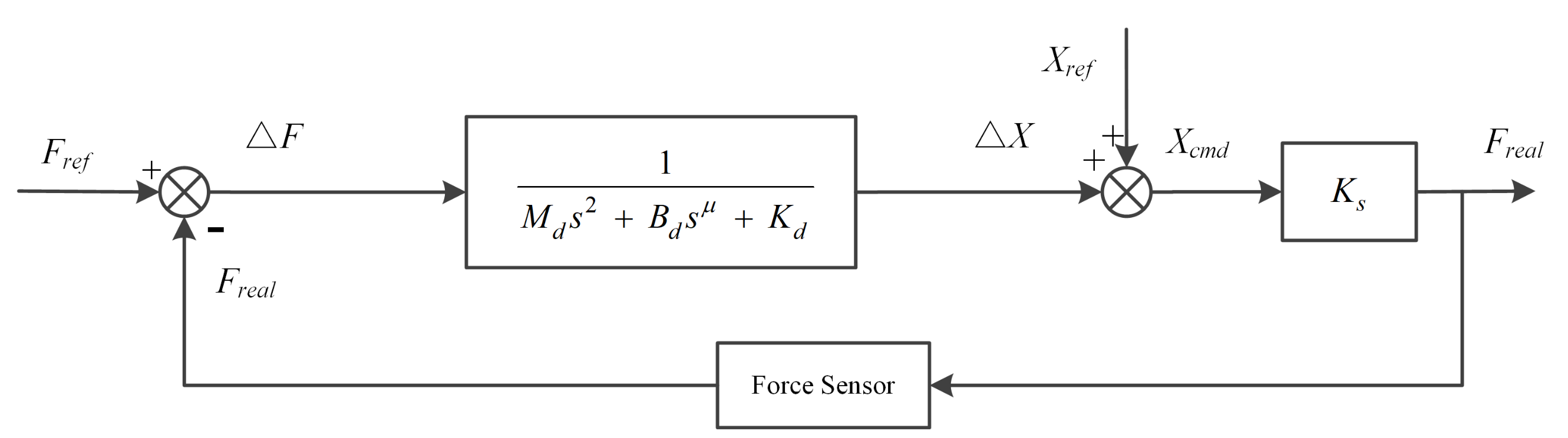
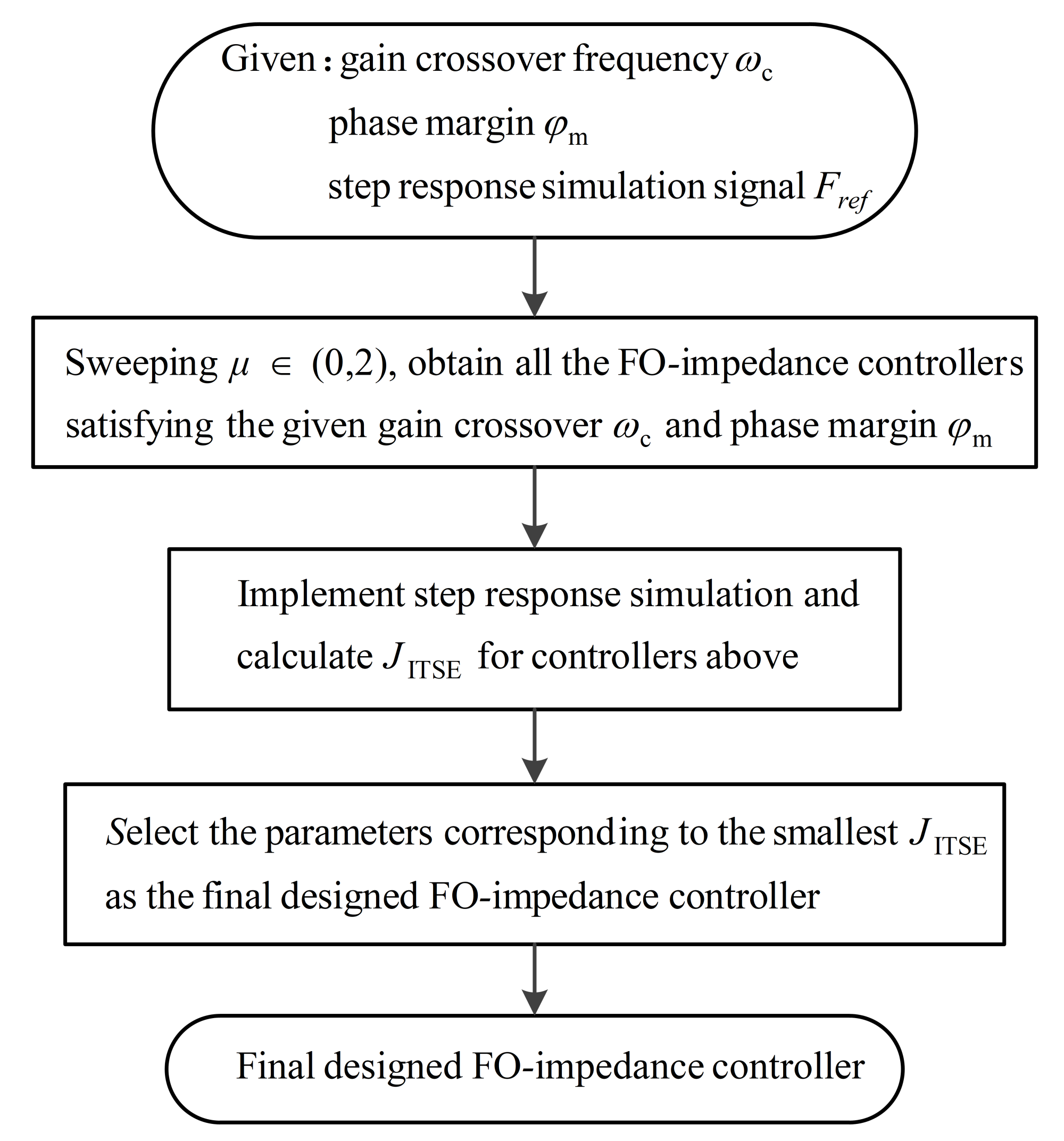
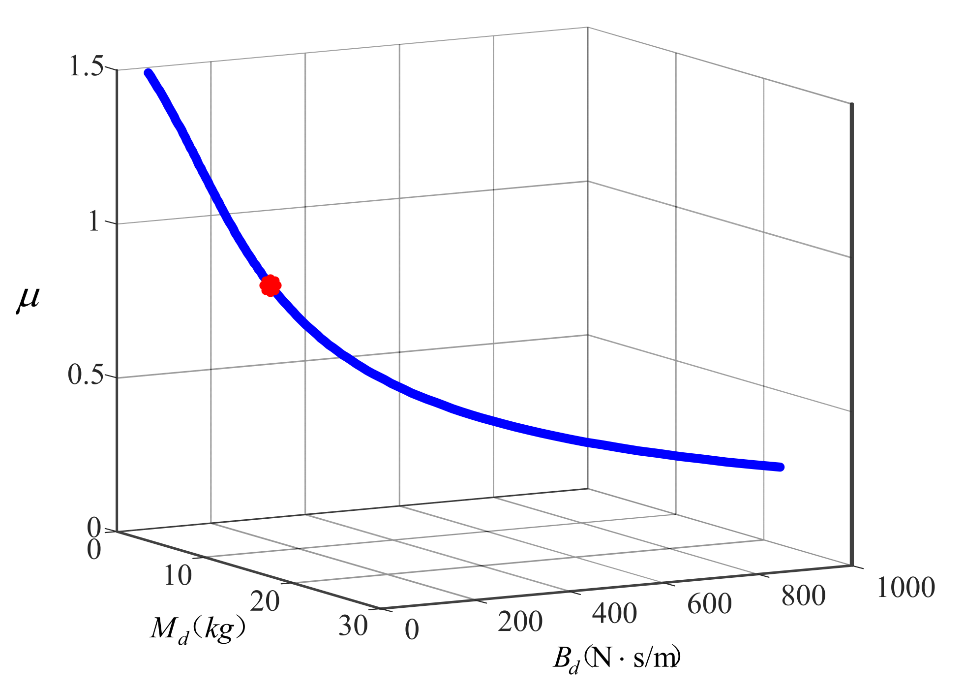
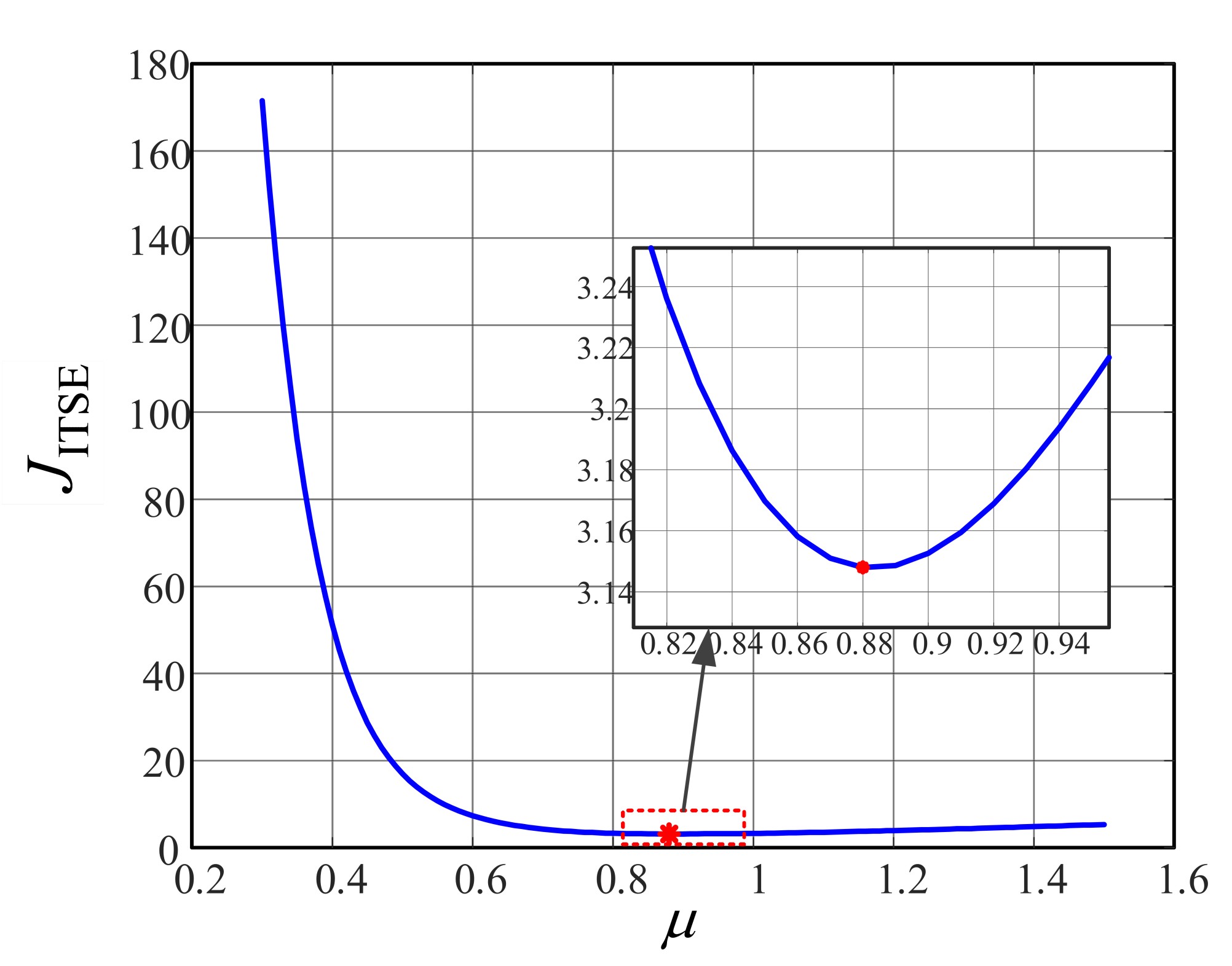
2.2.3. FO-Impedance Controller Design

Fractional order can describe the damping characteristics more accurately [23,24]. In order to improve the control performance of the system, a FO-impedance controller is proposed with a fractional order damping model as the controller structure shown in Figure 4.
The fractional-order dynamic differential equation corresponding to the traditional integer-order dynamics in Equation (1) is as follows:
M d x ¨ ( t ) + B d x μ ( t ) + K d x ( t ) = F ext ,
where μ is the fractional order.
The stiffness parameter K d is set as 0 to attenuate the force-tracking error [25]. The open-loop transfer function Equation (5) can be written as
G 0 f ( s ) = K s M d s 2 + B d s μ .
Substituting jw for s in Equation (16) yields
G 0 f ( jw ) = K s M d ( jw ) 2 + B d p 1 + B d p 2 j ,
where
p 1 = w u cos ( π 2 μ ) ,
p 2 = w u sin ( π 2 μ ) .
The gain of G 0 f ( s ) in frequency domain can be given as
G 0 f ( jw ) db = K s [ M d ( jw ) 2 + ( B d p 1 ) ] 2 + ( B d p 2 ) 2 .
The phase of G 0 f ( s ) can be written as
φ ( w ) = atan B d p 2 M d ( jw ) 2 + B d p 1 .
Given the fixed gain crossover frequency w c and the desired phase margin φ m , from Equations (7) and (8), we can obtain
a [ ( jw c ) 2 + bp 1 ] 2 + ( bp 2 ) 2 = 1 ,
φ m = π atan bp 2 ( jw c ) 2 + bp 1 ,
where
a = K s M d ,
b = M d B d .
According to Equations (24) and (25), we can establish the following equations:
b = tan ( π φ m ) ( jw c ) 2 p 2 p 1 tan ( π φ m ) ,
a = [ ( jw c ) 2 + bp 1 ] 2 + ( bp 2 ) 2 .
In the fractional-order impedance controller, given the crossover frequency and phase margin, there are three unknown parameters, M d , B d and fractional order μ . A time-domain specification, integral time square error (ITSE), is applied to design a FO-impedance controller systematically. Sweeping all of the value range of μ ( 0 , 2 ) , all of the FO-impedance controllers satisfying the pre-specified gain crossover frequency and phase margin can be obtained by Equations (24)–(27). Then, the step response simulation for all the FO-impedance controllers above can be implemented, and the corresponding ITSE value J ITSE can be calculated using Equation (28). Select the parameters corresponding to the smallest J ITSE as the final designed FO-impedance controller:
J ITSE = 0 tf t [ e ( t ) ] 2 dt ,
where t is the time, e ( t ) is the error between the actual value and the reference value, and tf is the control time.

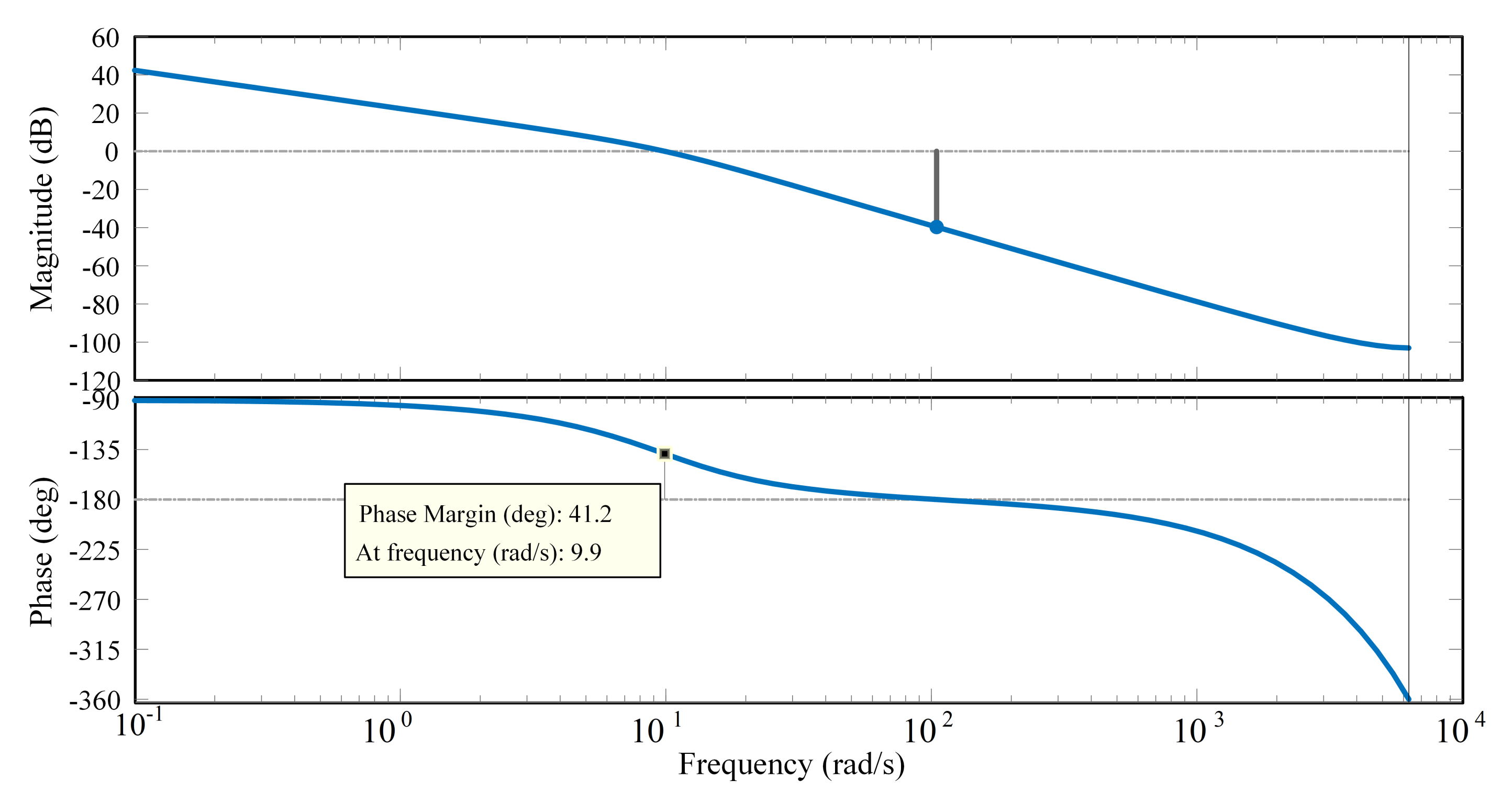
2.2.4. Design Procedure Illustration with an Example

The parameter setting rules of the FO-impedance controller are summarized with an example as follows with a flow chart shown in Figure 5:
(1) Given the gain crossover frequency w c = 10   rad / s , the desired phase margin φ m = 40 and step response signal F ref = 20 N.
(2) Sweeping all the μ ( 0 , 2 ) , all of the FO-impedance controllers satisfying the pre-specified gain crossover frequency w c and phase margin φ m can be obtained by Equations (24)–(27) as shown in Figure 6.
(3) Implement the step response simulations and calculate the J ITSE for all the FO-impedance controllers above. The correspondence diagram between μ and J ITSE is shown in Figure 7. The smallest J ITSE for which μ = 0.88 is marked as a red star in Figure 7.
(4) Select the parameters corresponding to the smallest J ITSE as the final designed FO-impedance controller, with M d = 11.4978 kg, and B d = 111.6108 N·s/m.

3. Simulation

The designed impedance controllers are applied to control the contact force between the end of robot manipulator and the environment in Z-axis direction. Given the frequency domain specifications, gain crossover frequency w c = 10   rad / s and phase margin φ m = 40 . Set the reference contact force F ref as 20 N, the system control sampling period as 0.0005 s, and the stiffness coefficient K s as 1293.83 N/m (the stiffness coefficient of the real spring in the experiment). According to the detailed process in Section 2, the IO-impedance and FO-impedance controllers can be designed and calculated. According to the given crossover frequency and phase margin, the parameters of the IO-impedance controller are obtained as follows: M d = 9.9113 kg, B d = 83.1658 N·s/m. For the FO-impedance controller, sweeping fractional order μ ( 0 , 2 ) , all the FO-impedance controllers which satisfy two specifications w c and phase margin φ m can be obtained. Then, J ITSE corresponding to the above FO-impedance controllers can be calculated through step response simulation with the step signal 20 N and simulation time 3.5 s. The smallest J ITSE is 3.1480, and we select the parameters corresponding to the smallest J ITSE as the final designed FO-impedance controller. The final selected FO-impedance controller parameters are as follows: μ = 0.88 , M d = 11.4978 kg, B d = 111.6108 N·s/m.

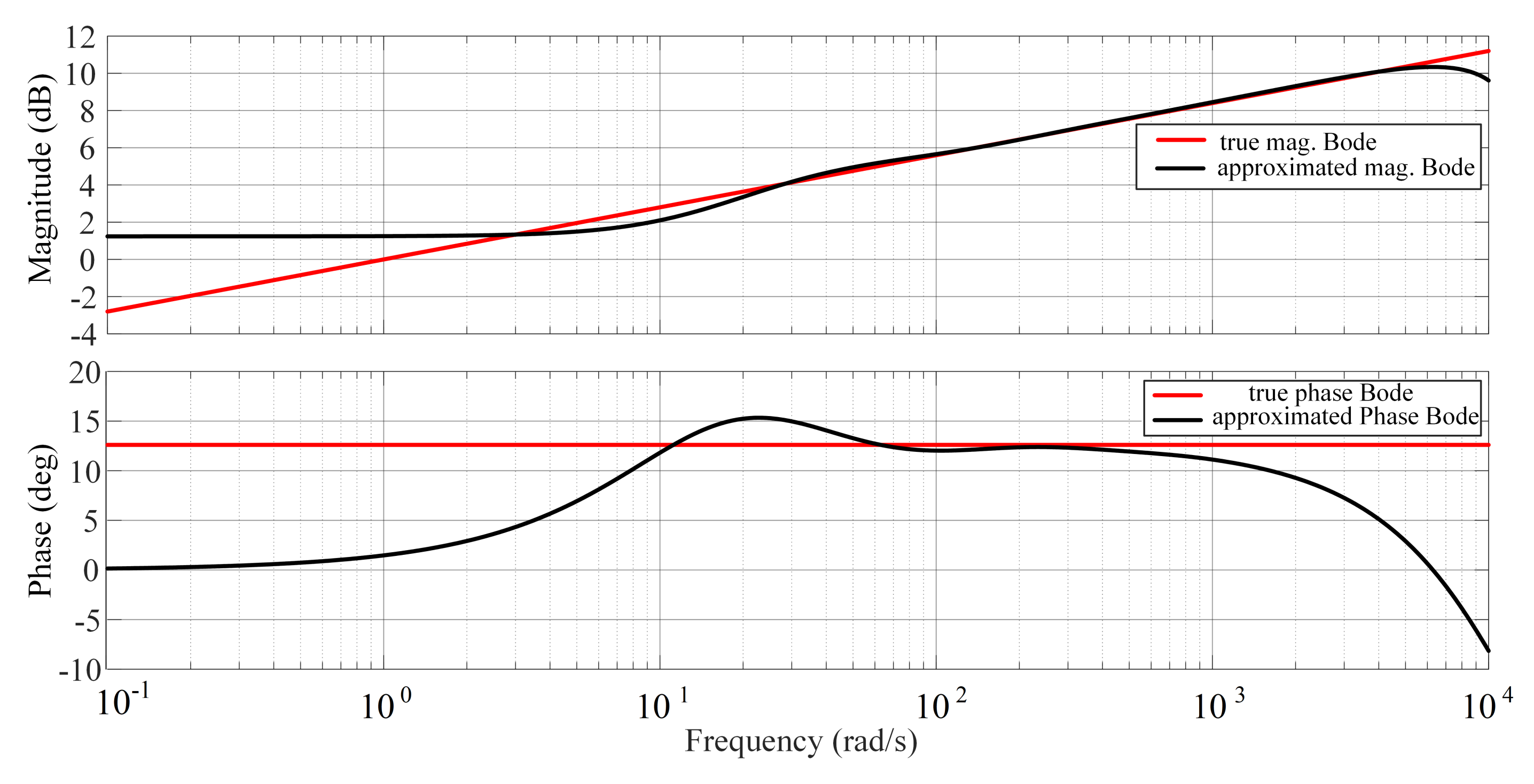
3.1. Fractional-Order Operator Implementation

The fractional-order operators s μ are implemented by the impulse response invariant discretization method [29]. The order of the approximate transfer function is 7, and the sampling frequency is 2 KHz. The discretized transfer function of the fractional order operator is shown as Equation (29). The comparison of the approximated bode diagram and true bode diagram are shown in Figure 8. Moreover, the discretized open-loop Bode plot of the FO-impedance controller is shown in Figure 9, and it is can be seen that the control system satisfies the given crossover frequency and phase margin specifications.
s μ = s 0.88 = Nums Dens ,
where Nums = z 7 4.2055 z 6 + 7.1551 z 5 6.2782 z 4 + 2.9892 z 3 0.7385 z 2 + 0.0802 z 0.0023 , Dens = 0.3953 z 7 1.6113 z 6 + 2.6413 z 5 2.2135 z 4 + 0.9929 z 3 0.2255 z 2 + 0.0213 z 0.0004 .

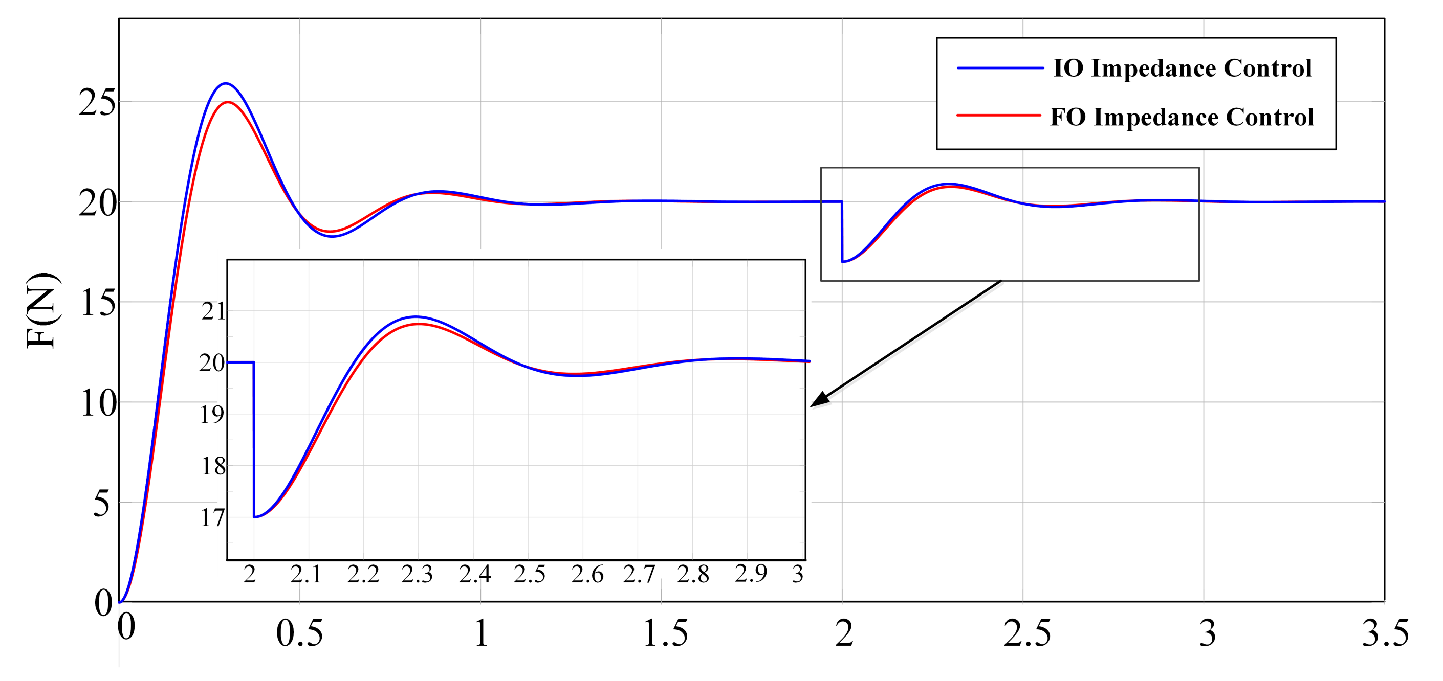
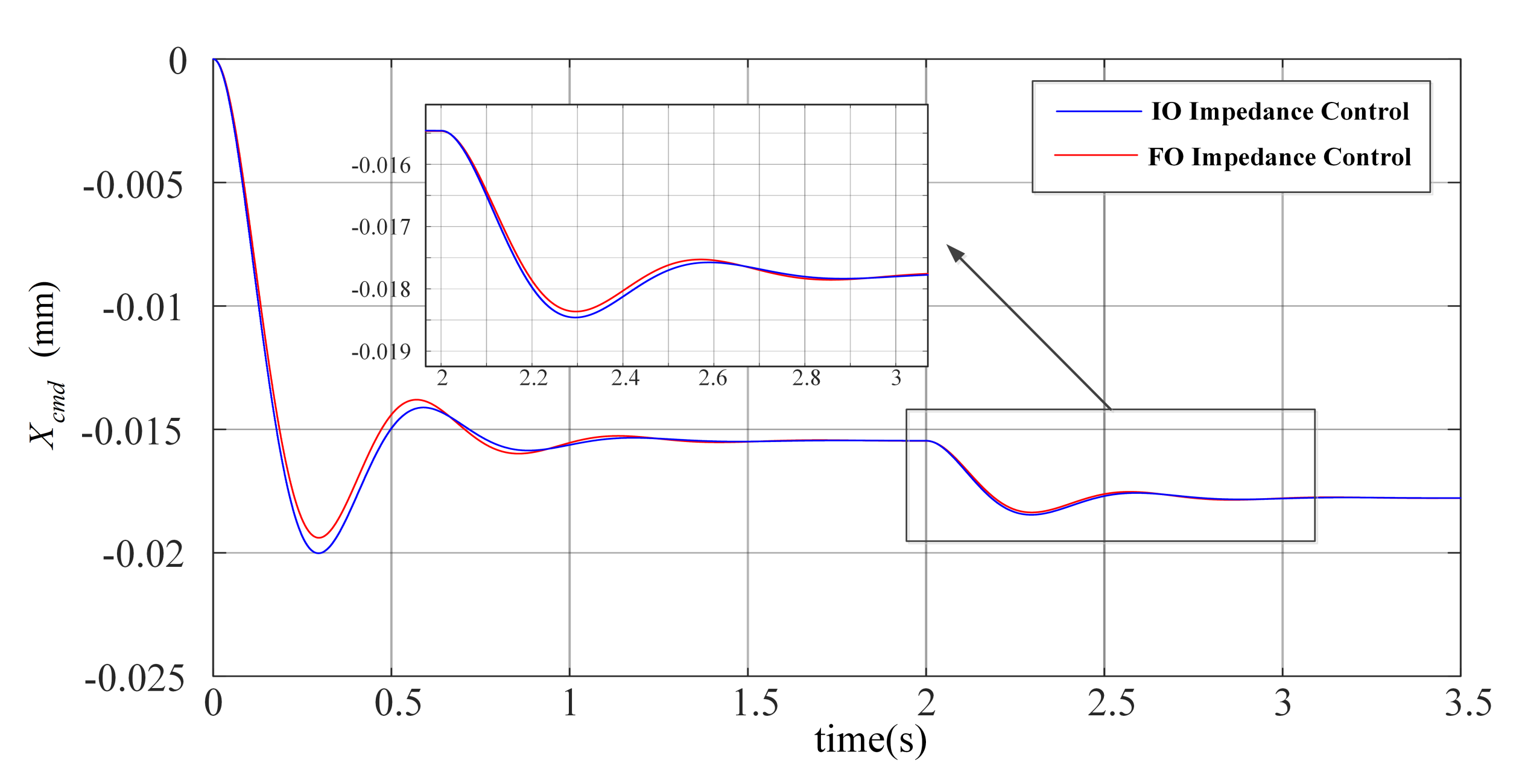
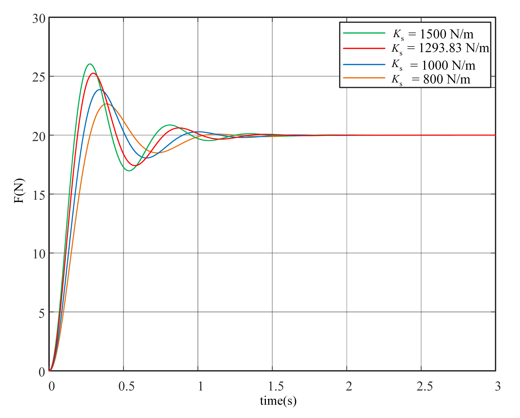
3.2. Step Response and Anti-Disturbance Simulation

To verify the force-tracking step response performance and anti-disturbance performance, the force control simulation is performed. The simulation results are shown in Figure 10, and the control signals are shown in Figure 11. Set the reference contact force F ref between the end of the robot manipulator and the environment in the Z-axis direction as 20 N.
The contact force step response simulations are performed, using the FO-impedance controller and IO-impedance controller. According to Figure 10, the overshoot of the IO-impedance controller is 29.4820%, the settling time is 0.9480 s, and the ITSE is 3.3350. The FO-impedance controller shows the desired force tracking performance; the overshoot is 25.3930%, the settling time is 0.9425 s and the ITSE is 3.1480. Moreover, in terms of the anti-disturbance test, F dis is added to the IO/FO-impedance control systems, which is −3 N. The stabilization time using the IO-impedance controller is 0.4070 s, and using the FO-impedance controller, it is 0.3875 s. The ITSE using the IO-impedance controller is 1.7426, and that using the FO-impedance controller is 1.7411. The comparison results are shown in Table 1. Therefore, the designed FO-impedance controller achieves much better contact force-tracking and anti-disturbance performance compared to the IO-impedance controller.
The robustness of the proposed FO-impedance controller is studied as follows. The designed FO-impedance controller with K s = 1293.83 N/m above is tested under the different spring coefficients, with K s = 1500 N/m, K s = 1000 N/m and K s = 800 N/m, as shown in Figure 12. The force step response results show that the designed FO-impedance controller is robust to the uncertain environment model.
In order to show the benefit of the proposed FO-impedance controller, more numerical examples are given as follows. The results are shown in Table 2 with different frequency domain specifications for the FO-impedance controller compared with the IO-impedance controller.

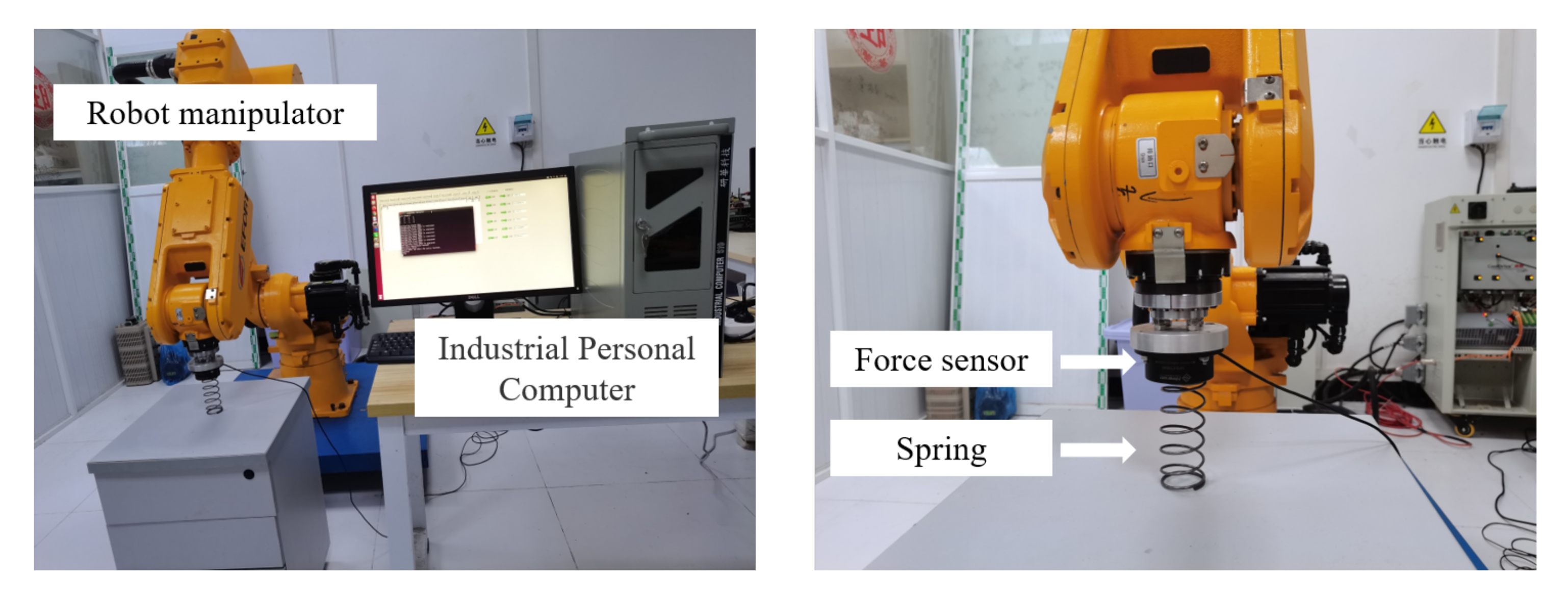
4. Experimental Verification

4.1. Experimental Setup

The experimental platform is mainly composed of an industrial computer, a robot manipulator, a force sensor, a spring, etc, as shown in Figure 13. The specifications of the experimental platform are given in Table 3. The robot controller software is developed in the industrial computer, which includes a real-time operating system, an Igh EtherCAT master station, and a user interface. The specific D-H parameters of the robot manipulator mechanical body are shown in Table 4. The servo drive communicates with the robot controller software as an EtherCAT slave station. The force sensor is installed at the end of the robot manipulator. The stiffness of the spring which is in contact with the end of the robot manipulator is 1293.83 N/m.

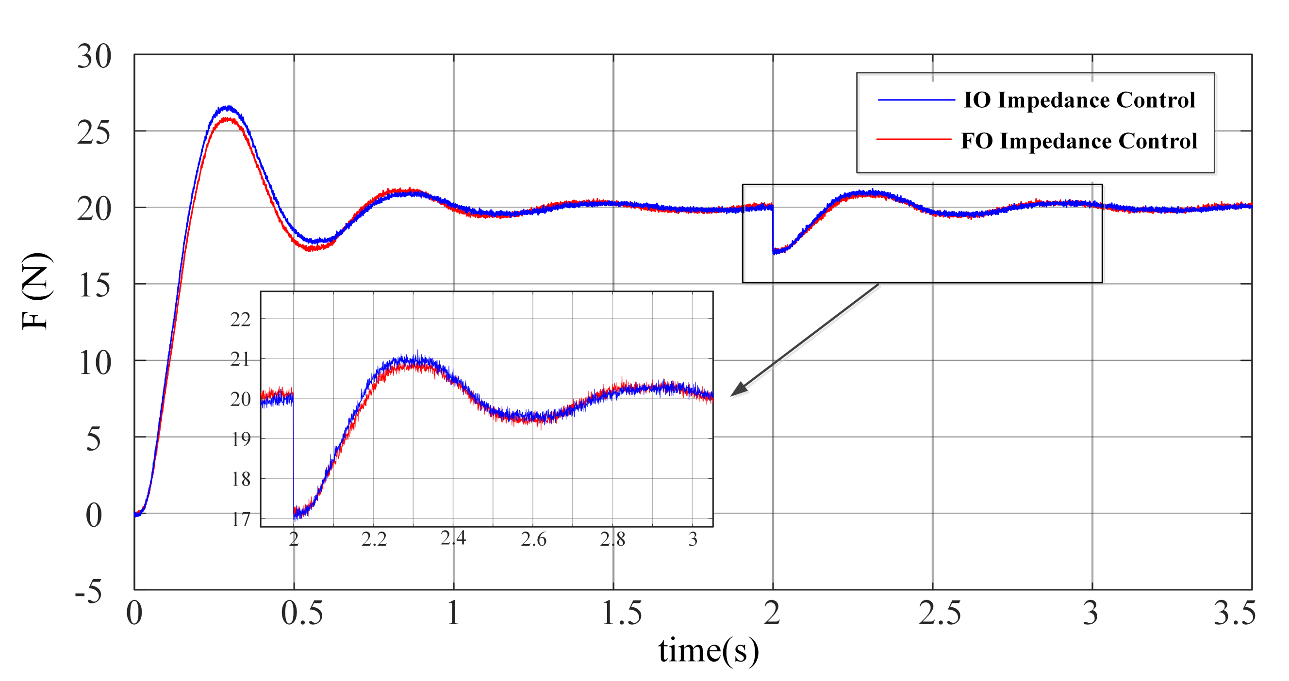
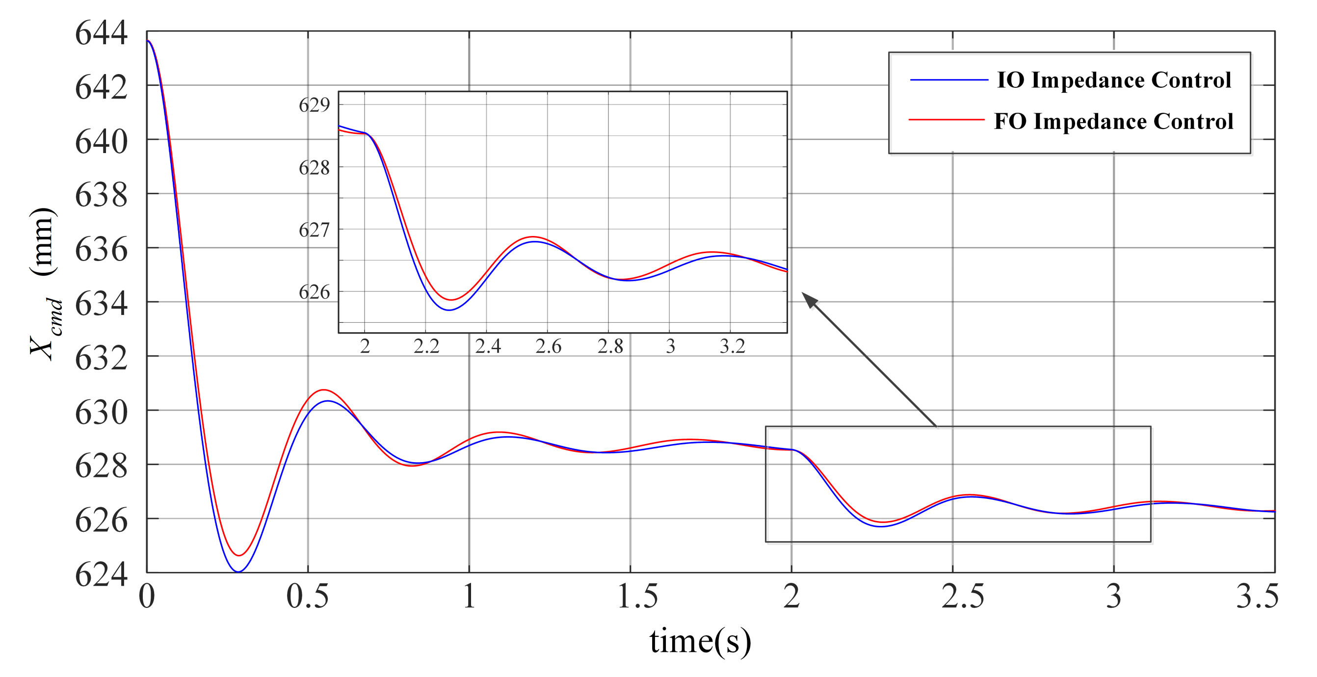
4.2. Step Response and Anti-Disturbance Test

The contact force experimental demonstration is performed to verify the force-tracking step response and anti-disturbance performance on the robot manipulator experimental platform. The initial pose of the robot manipulator is set as the force sensor pre-contacting with the spring. Set the reference contact force F ref between the end of the robot manipulator and the environment in the Z-axis direction as 20 N.
The contact force step response experiment is performed. The force responses are shown in Figure 14, and the control signals are shown in Figure 15 using the designed FO-impedance controller and IO-impedance controller presented in Section 2. As shown in Figure 14, the overshoot of the IO-impedance controller is 33.1100%, the settling time is 1.8550 s, and ITSE is 3.9286. The overshoot with the designed FO-impedance controller is 29.3050%, the settling time is 1.7030 s, and ITSE is 3.8681. Moreover, in terms of the anti-disturbance test, F dis is added to the IO/FO-impedance control systems, which is −3 N. The stabilization time of the IO-impedance controller is 1.0080 s and that of the FO-impedance controller is 0.9640 s. ITSE using the IO-impedance controller is 1.8998, and the using the FO-impedance controller is 1.8601. The comparison results are shown in Table 5. Thus, it is verified that the designed FO-impedance controller achieves better contact force tracking and anti-disturbance performance compared to the IO-impedance controller.

5. Conclusions

A fractional-order (FO) impedance controller is proposed in this paper. A systematic parameter-tuning method based on frequency-domain specifications is presented with a summarized procedure in details. The fair comparison between the FO-impedance controller and IO-impedance controller is addressed under the same design specifications via the simulation and robot manipulator experimental demonstration. The FO-impedance controller, with the optimized impedance modeling accuracy and more flexibility for control, outperforms the IO-impedance controller in step response performance and anti-disturbance robustness. The future research may be carried out from the direction of rejecting the dynamics disturbances of the robot manipulator and further improving the control performance of the FO-impedance controller.

Author Contributions

Conceptualization, Y.L.; Data curation, Y.D.; Funding acquisition, Y.L.; Investigation, X.L. (Xiaolian Liu) and P.C.; Methodology, Y.L.; Writing—original draft, Y.D.; Writing—review & editing, X.L. (Xin Luo) and Y.L. All authors have read and agreed to the published version of the manuscript.

Funding

This work was supported by the National Natural Science Foundation of China [51975234].

Data Availability Statement

Not applicable.

Conflicts of Interest

The authors declare no conflict of interest.

References

  1. Zhang, H.; Li, L.; Zhao, J.; Zhao, J. The hybrid force/position anti-disturbance control strategy for robot abrasive belt grinding of aviation blade base on fuzzy PID control. Int. J. Adv. Manuf. Technol. 2021, 114, 3645–3656. [Google Scholar] [CrossRef]
  2. Zhang, W.; Li, H.; Cui, L.; Li, H.; Zhang, X.; Fang, S.; Zhang, Q. Research progress and development trend of surgical robot and surgical instrument arm. Int. J. Med. Robot. Comput. Assist. Surg. 2021, 17, e2309. [Google Scholar] [CrossRef]
  3. Junge, K.; Hughes, J.; Thuruthel, T.G.; Iida, F. Improving robotic cooking using batch Bayesian optimization. IEEE Robot. Autom. Lett. 2020, 5, 760–765. [Google Scholar] [CrossRef]
  4. Zhang, J.; Liao, W.; Bu, Y.; Tian, W.; Hu, J. Stiffness properties analysis and enhancement in robotic drilling application. Int. J. Adv. Manuf. Technol. 2020, 106, 5539–5558. [Google Scholar] [CrossRef]
  5. Lu, H.; Zhao, X.; Tao, B.; Yin, Z. Online process monitoring based on vibration-surface quality map for robotic grinding. IEEE/ASME Trans. Mechatronics 2020, 25, 2882–2892. [Google Scholar] [CrossRef]
  6. Abdi, E.; Kulić, D.; Croft, E. Haptics in Teleoperated Medical Interventions: Force Measurement, Haptic Interfaces and Their Influence on User’s Performance. IEEE Trans. Biomed. Eng. 2020, 67, 3438–3451. [Google Scholar] [CrossRef] [PubMed]
  7. Yang, C.; Xie, Y.; Liu, S.; Sun, D. Force Modeling, Identification, and Feedback Control of Robot-Assisted Needle Insertion: A Survey of the Literature. Sensors 2018, 18, 561. [Google Scholar] [CrossRef] [Green Version]
  8. Hogan, N. Impedance Control: An Approach to Manipulation: Part II—Implementation. J. Dyn. Syst. Meas. Control. 1985, 107, 8–16. [Google Scholar] [CrossRef]
  9. Al-Shuka, H.F.; Leonhardt, S.; Zhu, W.H.; Song, R.; Ding, C.; Li, Y. Active impedance control of bioinspired motion robotic manipulators: An overview. Appl. Bionics Biomech. 2018, 2018, 8203054. [Google Scholar] [CrossRef] [PubMed]
  10. Tsumugiwa, T.; Yura, M.; Kamiyoshi, A.; Yokogawa, R. Development of mechanical-impedance-varying mechanism in admittance control. J. Robot. Mechatronics 2018, 30, 863–872. [Google Scholar] [CrossRef]
  11. Li, Z.; Xu, C.; Wei, Q.; Shi, C.; Su, C.Y. Human-inspired control of dual-arm exoskeleton robots with force and impedance adaptation. IEEE Trans. Syst. Man Cybern. Syst. 2018, 50, 5296–5305. [Google Scholar] [CrossRef]
  12. Duan, J.; Gan, Y.; Chen, M.; Dai, X. Adaptive variable impedance control for dynamic contact force tracking in uncertain environment. Robot. Auton. Syst. 2018, 102, 54–65. [Google Scholar] [CrossRef]
  13. Abu-Dakka, F.J.; Saveriano, M. Variable Impedance Control and Learning—A Review. Front. Robot. AI 2020, 7, 590681. [Google Scholar] [CrossRef] [PubMed]
  14. Zhang, F.; Lin, L.; Yang, L.; Fu, Y. Variable impedance control of finger exoskeleton for hand rehabilitation following stroke. Ind. Robot. Int. J. Robot. Res. Appl. 2019, 47, 23–32. [Google Scholar] [CrossRef]
  15. Liang, L.; Chen, Y.; Liao, L.; Sun, H.; Liu, Y. A novel impedance control method of rubber unstacking robot dealing with unpredictable and time-variable adhesion force. Robot. Comput. Integr. Manuf. 2021, 67, 102038. [Google Scholar] [CrossRef]
  16. Dong, J.; Xu, J.; Zhou, Q.; Hu, S. Physical human–robot interaction force control method based on adaptive variable impedance. J. Frankl. Inst. 2020, 357, 7864–7878. [Google Scholar] [CrossRef]
  17. Schmidt, A.; Gaul, L. On a critique of a numerical scheme for the calculation of fractionally damped dynamical systems. Mech. Res. Commun. 2006, 33, 99–107. [Google Scholar] [CrossRef]
  18. Kobayashi, Y.; Onishi, A.; Hoshi, T.; Kawamura, K.; Hashizume, M.; Fujie, M.G. Validation of viscoelastic and nonlinear liver model for needle insertion from in vivo experiments. In International Workshop on Medical Imaging and Virtual Reality; Springer: Berlin/Heidelberg, Germany, 2008; pp. 50–59. [Google Scholar]
  19. Sun, H.; Zhang, Y.; Baleanu, D.; Chen, W.; Chen, Y. A new collection of real world applications of fractional calculus in science and engineering. Commun. Nonlinear Sci. Numer. Simul. 2018, 64, 213–231. [Google Scholar] [CrossRef]
  20. Niu, H.; Chen, Y.; West, B.J. Why Do Big Data and Machine Learning Entail the Fractional Dynamics? Entropy 2021, 23, 297. [Google Scholar] [CrossRef]
  21. Chen, P.; Luo, Y. A Two-Degree-of-Freedom Controller Design Satisfying Separation Principle with Fractional Order PD and Generalized ESO. IEEE/ASME Trans. Mechatron. 2021, 27, 137–148. [Google Scholar] [CrossRef]
  22. Luo, Y.; Zhang, T.; Lee, B.; Kang, C.; Chen, Y. Fractional-order proportional derivative controller synthesis and implementation for hard-disk-drive servo system. IEEE Trans. Control Syst. Technol. 2013, 22, 281–289. [Google Scholar] [CrossRef] [Green Version]
  23. Dadkhah Khiabani, E.; Ghaffarzadeh, H.; Shiri, B.; Katebi, J. Spline collocation methods for seismic analysis of multiple degree of freedom systems with visco-elastic dampers using fractional models. J. Vib. Control 2020, 26, 1445–1462. [Google Scholar] [CrossRef]
  24. Wang, P.; Wang, Q.; Xu, X.; Chen, N. Fractional critical damping theory and its application in active suspension control. Shock Vib. 2017, 2017, 2738976. [Google Scholar] [CrossRef]
  25. Jung, S.; Hsia, T.C. Stability and convergence analysis of robust adaptive force tracking impedance control of robot manipulators. In Proceedings of the Proceedings 1999 IEEE/RSJ International Conference on Intelligent Robots and Systems. Human and Environment Friendly Robots with High Intelligence and Emotional Quotients, Kyongju, Republic of Korea, 17–21 October 1999; Volume 2, pp. 635–640. [Google Scholar]
  26. Lee, K.; Buss, M. Force tracking impedance control with variable target stiffness. IFAC Proc. Vol. 2008, 41, 6751–6756. [Google Scholar] [CrossRef] [Green Version]
  27. Kim, T.; Kim, H.S.; Kim, J. Position-based impedance control for force tracking of a wall-cleaning unit. Int. J. Precis. Eng. Manuf. 2016, 17, 323–329. [Google Scholar] [CrossRef]
  28. Luo, Y.; Chen, Y. Fractional order [proportional derivative] controller for a class of fractional order systems. Automatica 2009, 45, 2446–2450. [Google Scholar] [CrossRef]
  29. Impulse Response Invariant Discretization of Fractional Order Integrators/Dierentiators. Available online: http://www.mathworks.com/matlabcentral/fileexchange/21342-impulse-response-invariant-discretization-of-fractional-orderintegrators-dierentiators (accessed on 1 September 2020).
Figure 1. Dynamic model of impedance-control mechanical system.
Fractalfract 06 00684 g001
Figure 2. Robot manipulator impedance-control system diagram.
Fractalfract 06 00684 g002
Figure 3. Simplified robot manipulator impedance-control system diagram.
Fractalfract 06 00684 g003
Figure 4. FO-impedance controller.
Fractalfract 06 00684 g004
Figure 5. FO-impedance design procedure flow chart.
Fractalfract 06 00684 g005
Figure 6. All the parameters satisfying the pre-specified gain crossover frequency and phase margin.
Fractalfract 06 00684 g006
Figure 7. J ITSE corresponding to the μ .
Fractalfract 06 00684 g007
Figure 8. Comparison of approximated bode diagram and true bode diagram.
Fractalfract 06 00684 g008
Figure 9. Bode diagram of fractional-order impedance controller.
Fractalfract 06 00684 g009
Figure 10. Simulation comparison of FO/IO-impedance controller.
Fractalfract 06 00684 g010
Figure 11. Control signal comparison of FO/IO-impedance controller in simulation.
Fractalfract 06 00684 g011
Figure 12. Robustness test for FO-impedance controller.
Fractalfract 06 00684 g012
Figure 13. The experimental platform.
Fractalfract 06 00684 g013
Figure 14. Experimental comparison of FO/IO-impedance controller.
Fractalfract 06 00684 g014
Figure 15. Control signal comparison of FO/IO-impedance controller in experiment.
Fractalfract 06 00684 g015
Table 1. Comparison of simulation performance between FO/IO-impedance controller.
Step Response TestAnti-Disturbance Test
Overshoot
(%)
Settling Time
(s)
ITSEStabilization Time
(s)
ITSE
IO-impedance29.48200.94803.33500.40701.7426
FO-impedance25.39300.94253.14800.38751.7411
Performance
improvement
4.0890%0.5802%5.6072%4.7912%0.0861%
Table 2. Performance of FO-impedance controller compared with that of IO-impedance controller under different gain crossover w c and phase margin φ m .
w c = 10 rad/s
φ m = 40
w c = 10 rad/s
φ m = 45
w c = 15 rad/s
φ m = 40
w c = 15 rad/s
φ m = 45
delta14.6897%10.4499%7.4661%6.3878%
ts2.6912%1.3616%0.1577%0.8511%
ITSE3.8581%0.9018%1.9599%1.0003 %
Table 3. Model and description of the experimental platform.
ItemsBrand and ModelDescription
Robot manipulator
mechanical body
EFFORT-ERC20C-C10Degree-of-freedom: 6
Maximum load: 20 kg
Industrial computerADVANTECHMain board: advantech AIMB-785
Processor: Intel CoreTM i7-7700/3.6 GHz
Servo driveTSINO DYNATRON
CoolDrive R6
Maximum EtherCAT communication
frequency: 4 KHz
Force sensorHPS-FT060ERange in Z-axis: ±1000 N
Measurement accuracy: 0.4 N
Maximum EtherCAT communication
frequency: 2 KHz
Spring Stiffness: 1293.83 N/m
Table 4. The D-H parameters of ER20C-C10.
Link iLink Length
( a i 1 ) (mm)
Link Twist
( α i 1 ) (degree)
Joint Offset
( d i ) (mm)
Joint Angle
( θ i ) (degree)
1168.4690504 θ 1
2781.5500 θ 2 + 90
3140.3490−0.3 θ 3
40−90760.39 θ 4
50900 θ 5
600125 θ 6
Table 5. Comparison of experimental performance between FO/IO-impedance controller.
Step Response TestAnti-Disturbance Test
Overshoot
(%)
Settling Time
(s)
ITSEStabilization
Time (s)
ITSE
IO-impedance33.11001.85503.92861.00801.8998
FO-impedance29.30501.70303.86810.96401.8601
Performance improvement11.4920%8.1941%1.5400%4.3651%2.0897%
Publisher’s Note: MDPI stays neutral with regard to jurisdictional claims in published maps and institutional affiliations.

