Fractal Antennas: An Historical Perspective


 and
and
Abstract
:1. Introduction
2. About the Fractal Geometry
2.1. Recursive Relation Based
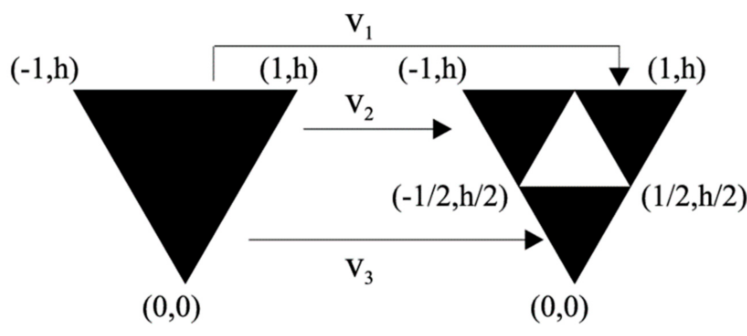
2.2. Iterated Function System (IFS)
2.3. L-Systems
2.4. Random
3. Fractals in Antenna Engineering
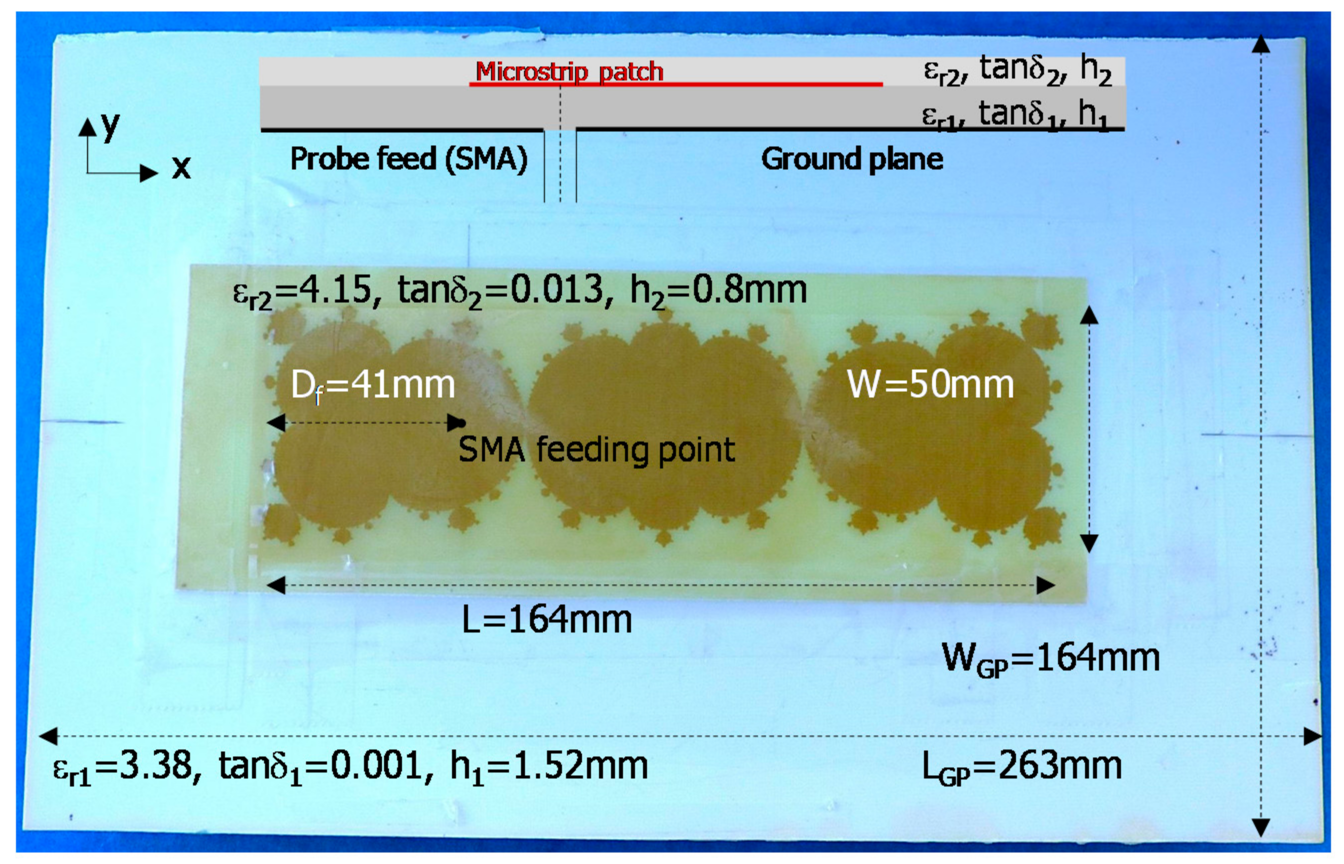
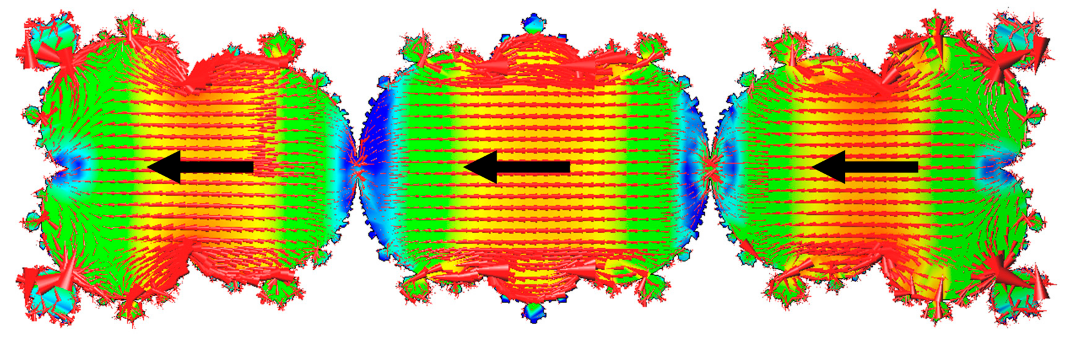
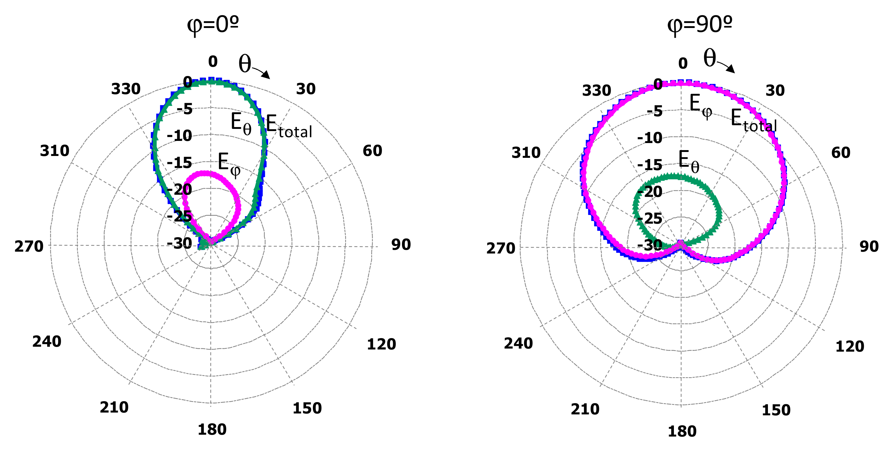
3.1. Mandelbrot
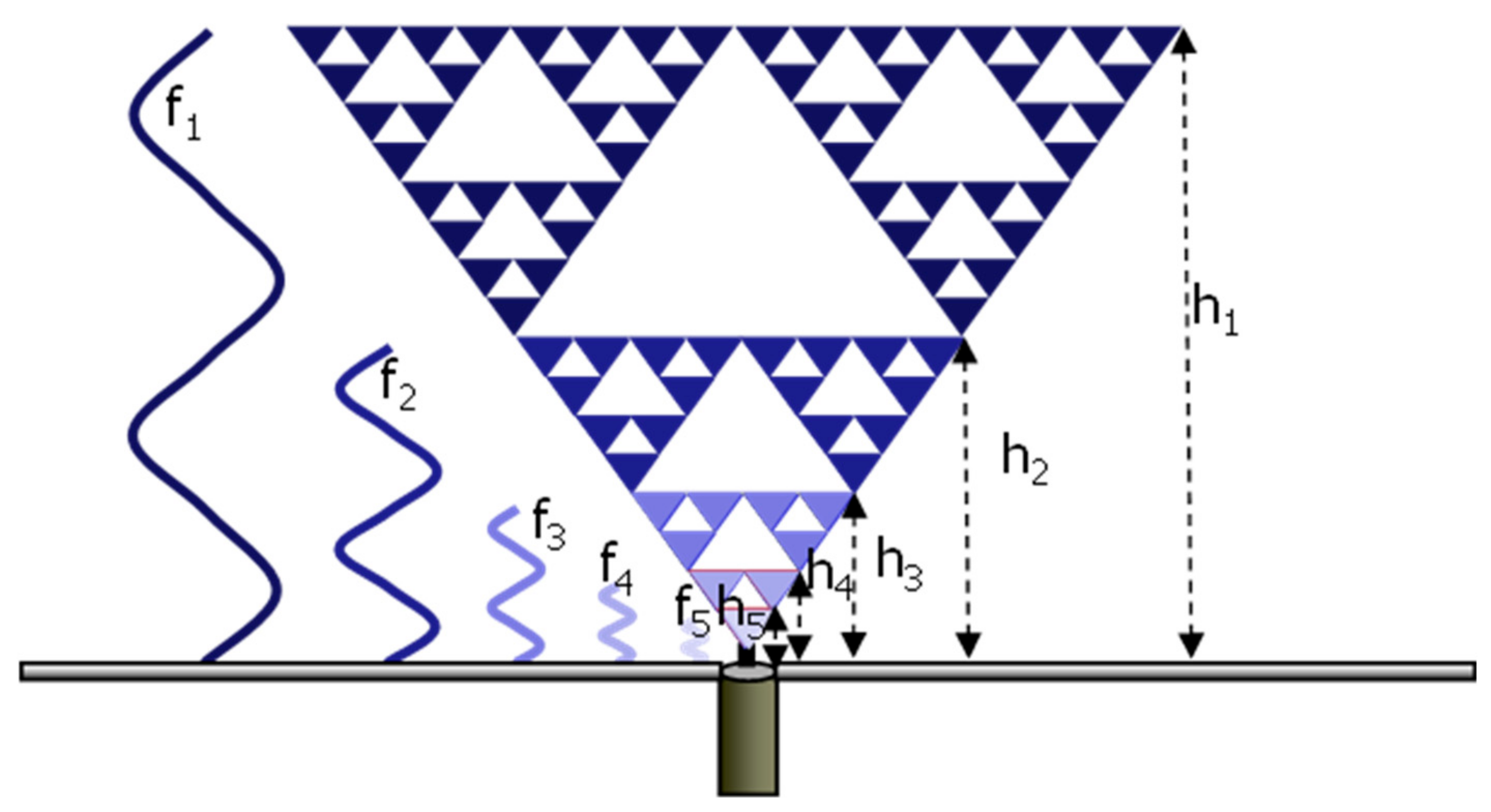
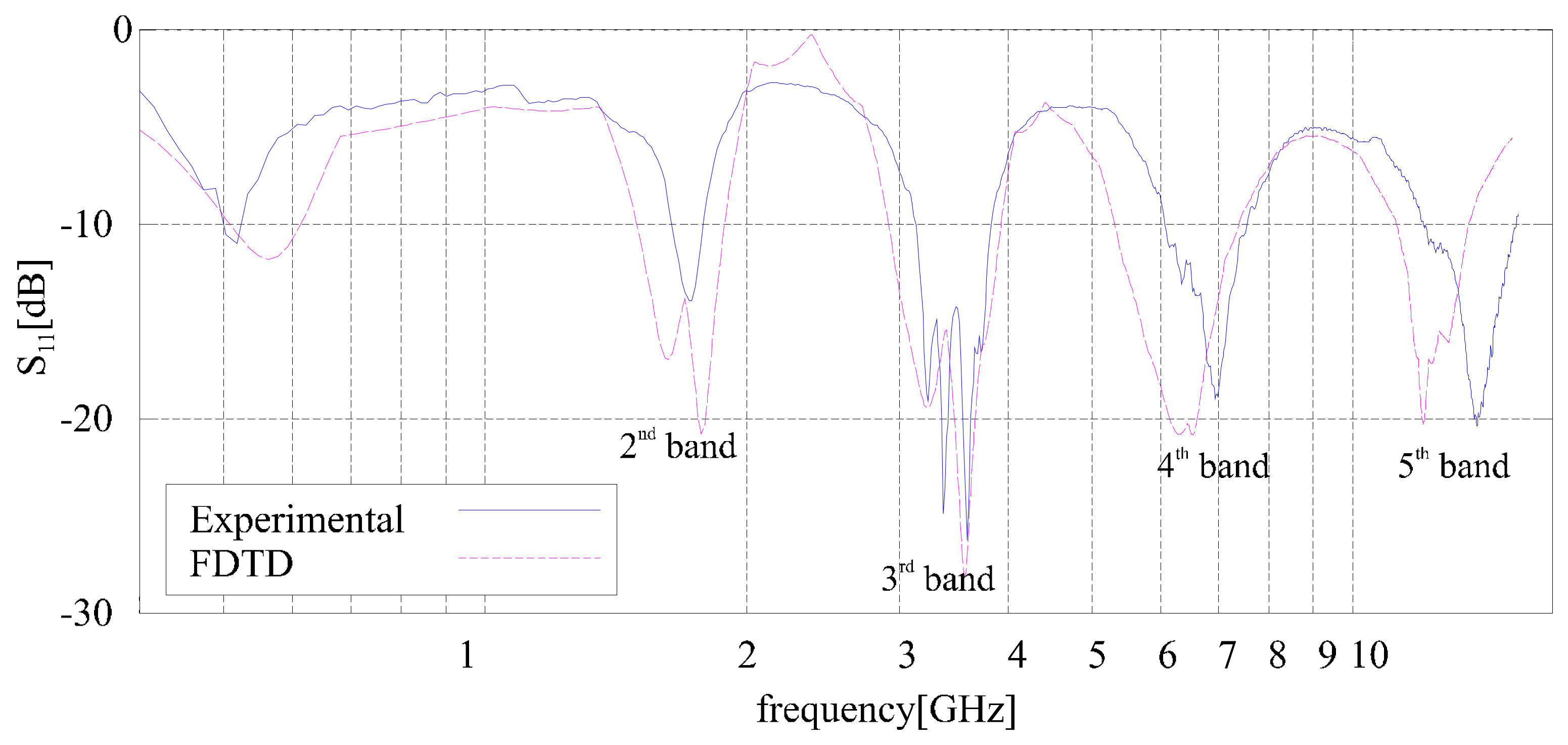
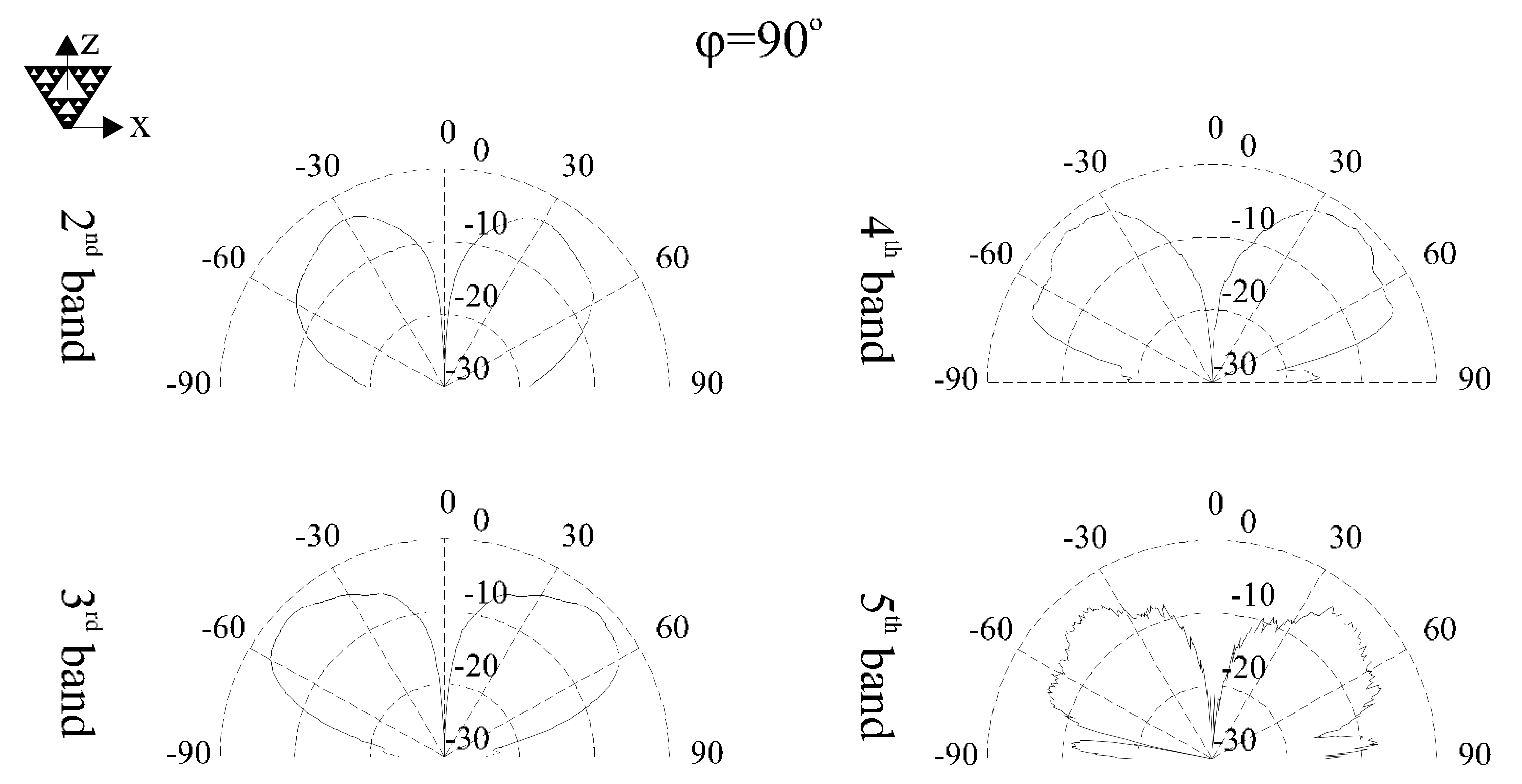
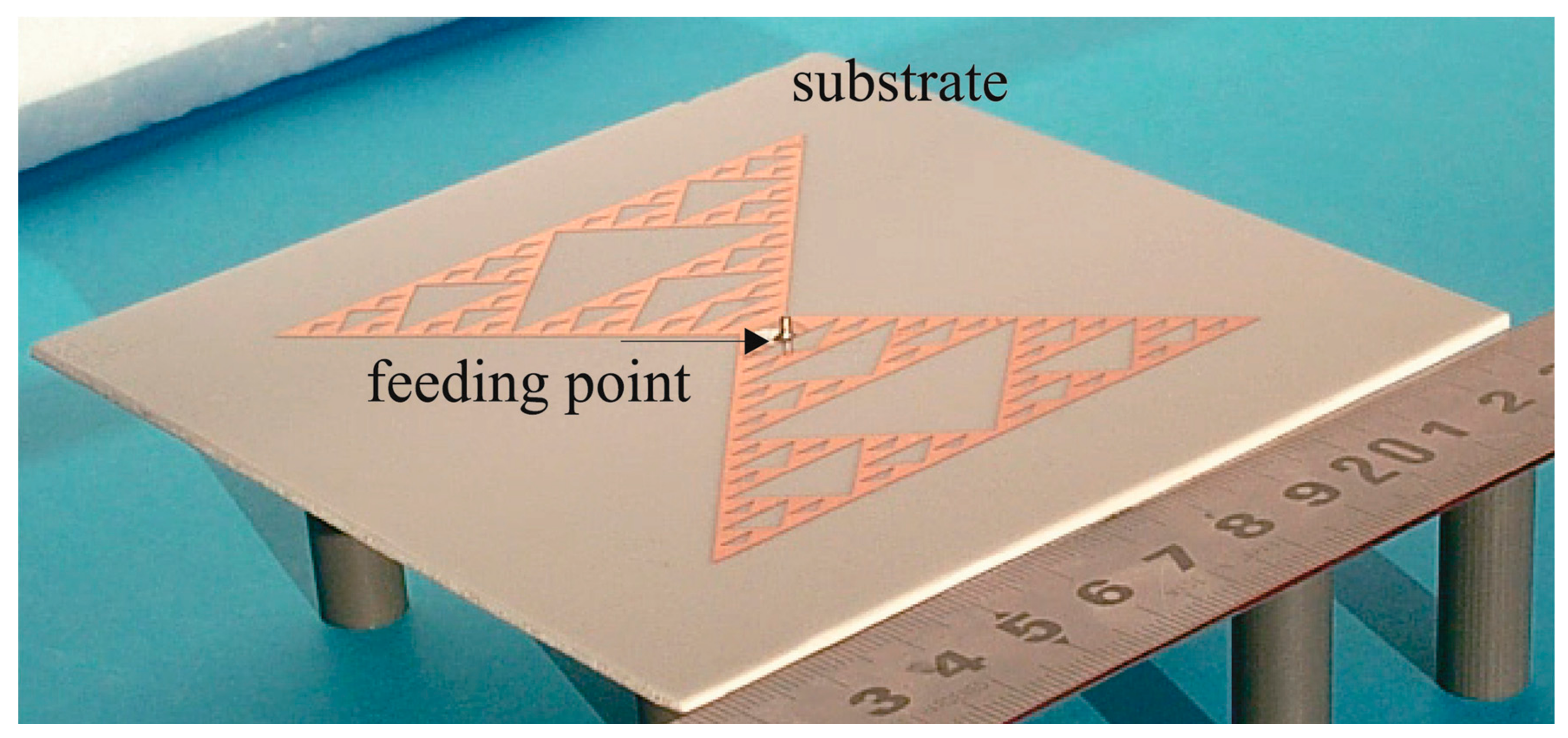
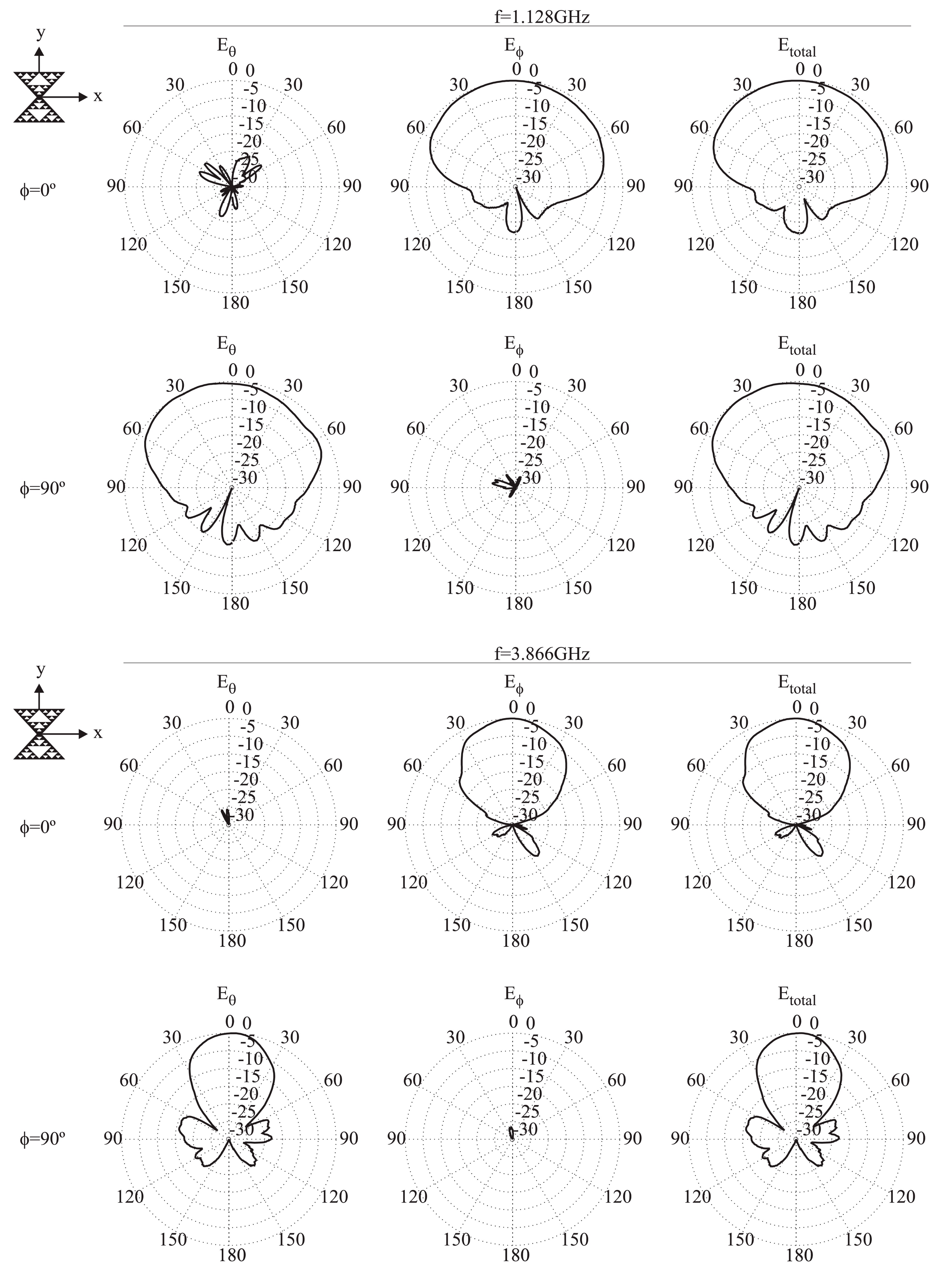
3.2. Sierpiński
3.3. Koch
3.4. Hilbert
3.5. Cantor
3.6. Minkowski
3.7. Peano
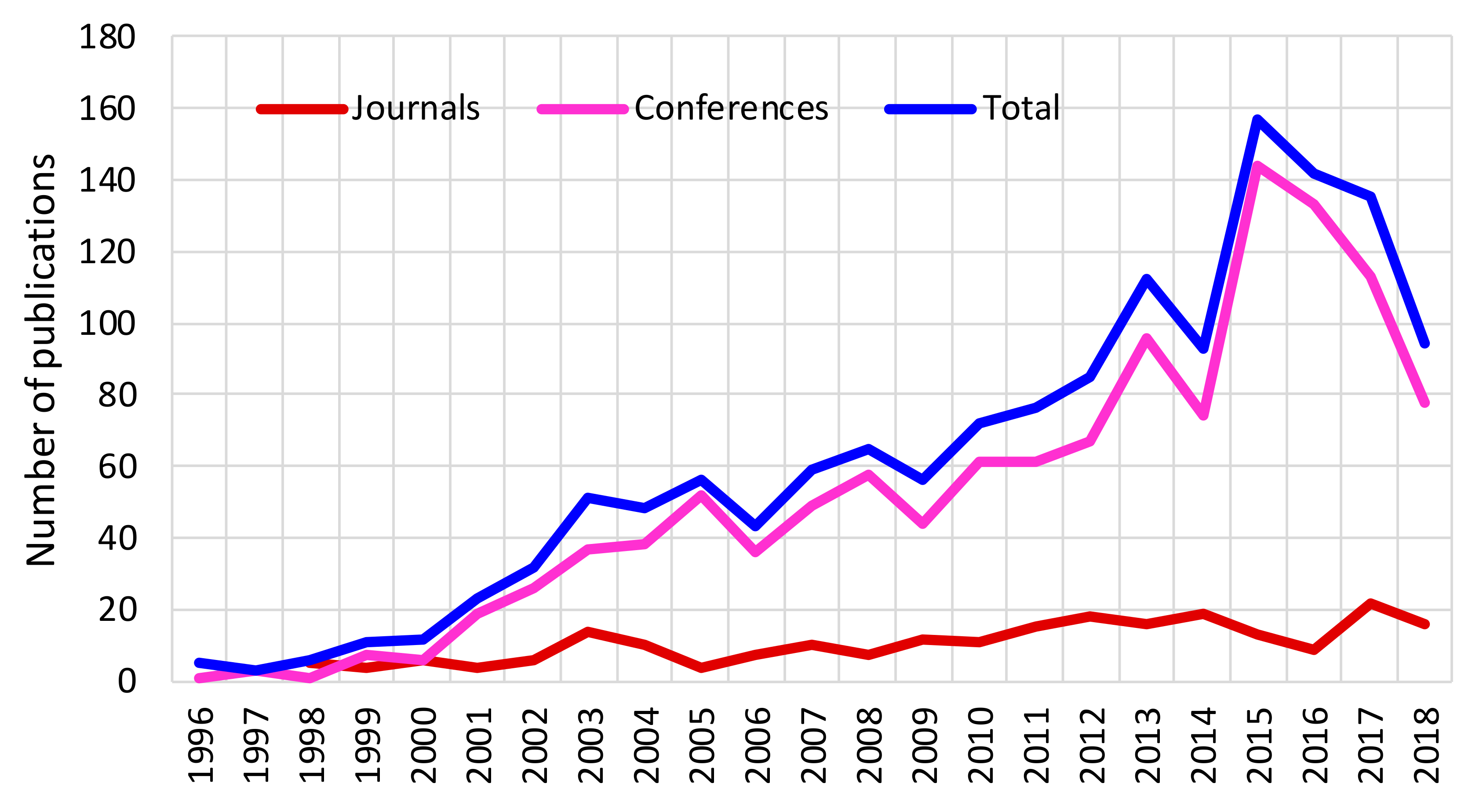
4. Evolution of Publications in the Fractal Antenna Field
5. Conclusions
Author Contributions
Funding
Conflicts of Interest
References
- Mandelbrot, B. The Fractal Geometry of Nature; W. H. Freeman and Company: San Francisco, CA, USA, 1982. [Google Scholar]
- Werner, D.H.; Haupt, R.L.; Werner, P.L. Fractal antenna engineering: The theory and design of fractal antenna arrays. IEEE Antennas Propag. Mag. 1999, 41, 37–58. [Google Scholar] [CrossRef] [Green Version]
- Gianvittorio, J.P.; Rahmat-Samii, Y. Fractal antennas: A novel antenna miniaturization technique, and applications. IEEE Antennas Propag. Mag. 2002, 44, 20–36. [Google Scholar] [CrossRef]
- Anguera, J.; Puente, C.; Borja, C.; Soler, J. Fractal-Shaped Antennas: A Review. Encyclopedia of RF and Microwave Engineering; Chang, K., Ed.; Wiley: Chichester, NY, USA, 2005; Volume 2, pp. 1620–1635. [Google Scholar]
- Puente, C.; Pous, R. Fractal design of multiband and low side-lobe arrays. IEEE Trans. Antennas Propag. 1996, 44, 730. [Google Scholar] [CrossRef] [Green Version]
- Cohen, N. Fractal antenna applications in wireless telecommunications. In Professional Program Proceedings, Electronic Industries Forum of New England; IEEE: Boston, MA, USA, 1997; pp. 43–49. [Google Scholar]
- Werner, D.H.; Ganguly, S. An overview of fractal antenna engineering research. IEEE Antennas Propag. Mag. 2003, 45, 38–57. [Google Scholar] [CrossRef] [Green Version]
- Falconer, K. Fractal Geometry: Mathematical Foundations and Applications; John Wiley: Chichester, UK, 1990. [Google Scholar]
- Peitgen, H.O.; Jürgens, J.; Saupe, D. Chaos and Fractals: New Frontiers of Science; Springer: Berlin / Heidelberg, Germany, 1990. [Google Scholar]
- Minervino, D.R.; D’Assunçâo, A.G.; Peixeiro, C. Mandelbrot Fractal Microstrip Antennas. Microw. Opt. Technol. Lett. 2016, 58, 83–86. [Google Scholar] [CrossRef]
- Silva Neto, V.P.; D’Assunção, A.G. Iterative full-wave analysis of Mandelbrot-inspired fractal patch antenna on textile substrate for UWB applications. Int. J. Antennas Propag. 2017, 2017. [Google Scholar] [CrossRef]
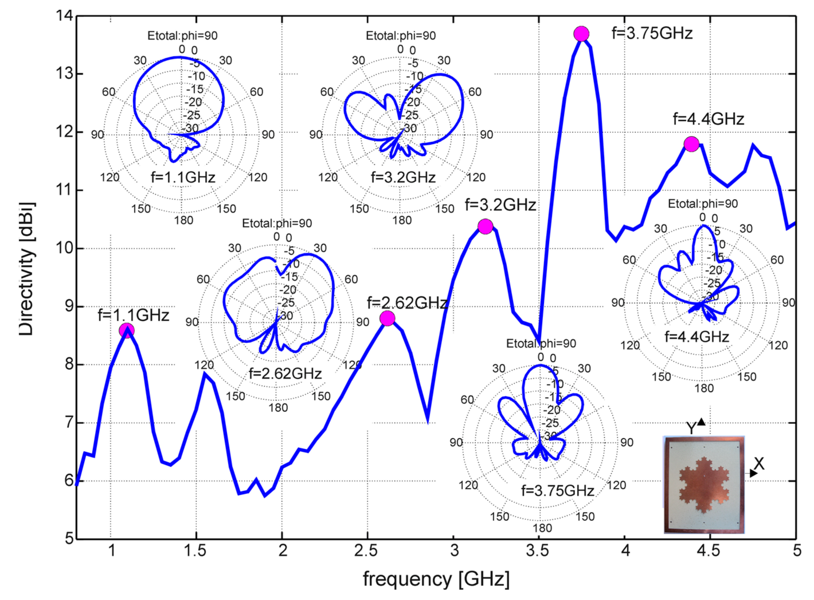
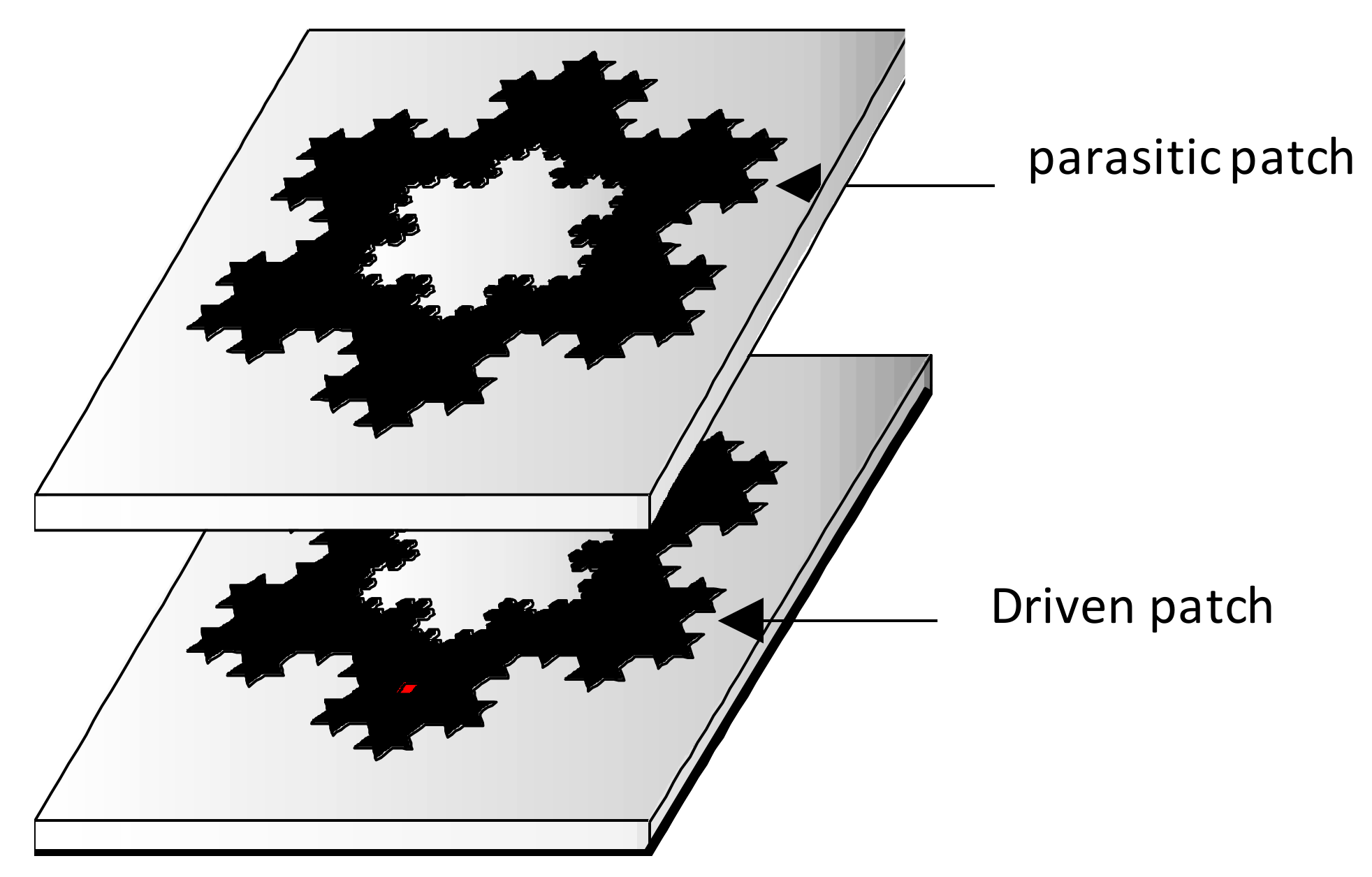
- Anguera, J.; Andújar, A.; Benavente, S.; Jayasinghe, J.; Kahng, S. High-Directivity Microstrip Antenna with Mandelbrot Fractal Boundary. IET Microw. Antennas Propag. 2018, 12, 569–575. [Google Scholar] [CrossRef]
- Puente, C.; Romeu, J.; Pous, R.; Cardama, A. On the behavior of the Sierpinski multiband fractal antenna. IEEE Trans. Antennas Propag. 1998, 46, 517–524. [Google Scholar] [CrossRef] [Green Version]
- Puente, C. Fractal Antennas. Ph.D. Thesis, Universitat Politècnica de Catalunya, Barcelona, Spain, 1997. [Google Scholar]
- Borja, C. Fractal Microstrip Patch Antennas with Fractal Perimeter and Self-Affine Properties. Ph.D. Thesis, Universitat Politècnica de Catalunya, Barcelona, Spain, 2001. [Google Scholar]
- Anguera, J. Fractal and BroadBand Techniques for Miniature, Multifrequency and High-Directivity Microstrip Patch Antennas. Ph.D. Thesis, Universitat Politècnica de Catalunya, Barcelona, Spain, 2003. [Google Scholar]
- Soler, J. Novel Multifrequency and Small Monopole Antenna for Wireless and Mobile Applications. Ph.D. Thesis, Universitat Politècnica de Catalunya, Barcelona, Spain, 2004. [Google Scholar]
- Gianvittorio, J.P.; Romeu, J.; Blanch, S.; Rahmat-Samii, Y. Self-similar prefractal frequency selective surfaces for multiband and dual-polarized applications. IEEE Trans. Antennas Propag. 2003, 51, 3088–3096. [Google Scholar] [CrossRef] [Green Version]
- Kim, Y.; Jaggard, D.L. The fractal random array. Proc. IEEE 1986, 74, 1278–1280. [Google Scholar] [CrossRef]
- Puente, C.; Claret, J.; Sagues, F.; Romeu, J.; López-Salvans, M.Q.; Pous, R. Multiband properties of a fractal tree antenna generated by electrochemical deposition. IEE Electron. Lett. 1996, 32, 2298–2299. [Google Scholar] [CrossRef]
- Rmili, H.; el Mrabet, O.; Floc’h, J.; Miane, J. Study of an Electrochemically-Deposited 3-D Random Fractal Tree-Monopole Antenna. IEEE Trans. Antennas Propag. 2007, 55, 1045–1050. [Google Scholar] [CrossRef]
- Rmili, H.; DoniaI, O.; Trad, I.B.; Floch, J.M.; Mittra, R. Investigation of a Random-Fractal Antenna Based on a Natural Tree-Leaf Geometry. Int. J. Antennas Propag. 2017, 2017, 7. [Google Scholar] [CrossRef]
- Laadhar, L.; Zaraouan, M.; Oueslati, D.; Floch, J.M.; Rmili, H. Investigation on Cellular-Automata Irregular-Fractal Ultra-Wideband Slot-Antennas. Microw. Opt. Technol. Lett. 2015, 57, 2506–2514. [Google Scholar] [CrossRef]
- Rmili, H.; Floch, R.; Zangar, H. Experimental of a 2-D Irregular fractal jet printed antenna. IEEE Antennas Wirel. Propag. Lett. 2009, 8, 328–331. [Google Scholar] [CrossRef]
- Anguera, J.; Puente, C.; Borja, C.; Montero, R.; Soler, J. Small and High Directivity Bowtie Patch Antenna based on the Sierpinski Fractal. Microw. Opt. Technol. Lett. 2001, 31, 239–241. [Google Scholar] [CrossRef]
- Borja, C.; Font, G.; Blanch, S.; Romeu, J. High Directivity Fractal Boundary Microstrip Patch Antenna. IEE Electron. Lett. 2000, 36, 778–779. [Google Scholar] [CrossRef] [Green Version]
- Anguera, J.; Montesinos, G.; Puente, C.; Borja, C.; Soler, J. An Under-Sampled High Directivity Microstrip Patch Array with a Reduced Number of Radiating elements Inspired on the Sierpinski Fractal. Microw. Opt. Technol. Lett. 2003, 37, 100–103. [Google Scholar] [CrossRef]
- Anguera, J.; Puente, C.; Borja, C.; Montero, R. Bowtie Microstrip Patch Antenna based on the Sierpinski Fractal. IEEE Antennas Propag. Soc. Int. Symp. 2001, 3, 162–165. [Google Scholar]
- Montesinos, G.; Anguera, J.; Puente, C.; Borja, C. The Sierpinski fractal bowtie patch: A multifracton-mode antenna. IEEE Antennas Propag. Soc. Int. Symp. 2002, 4, 542–545. [Google Scholar]
- Anguera, J.; Montesinos, G.; Puente, C.; Borja, C.; Soler, J. Fracton-Mode Arrays using Microstrip Fractal Sierpinski Based Radiators. In Proceedings of the Antenna Systems 2003, Denver, CO, USA, 8–9 October 2003. [Google Scholar]
- Anguera, J.; Montesinos, G.; Puente, C.; Borja, C.; Soler, J. Scanning properties in fracton-mode microstrip arrays using elements inspired on the Sierpinski fractal. In Proceedings of the IEEE Antennas and Propagation Society International Symposium, Monterey, CA, USA, 20–26 June 2004. [Google Scholar]
- Anguera, J.; Puente, C.; Borja, C.; Soler, J. Scanning properties in an under-sampled microstrip array using Sierpinski fractal-inspired elements. In Proceedings of the 27th ESA Antenna Technology Workshop on Innovative Periodic Antennas, Santiago de Compostela, Spain, 9–11 March 2004. [Google Scholar]
- Anguera, J.; Daniel, J.P.; Borja, C.; Mumbru, J.; Puente, C.; Leduc, T.; Laeveren, N.; Van Roy, P. Metallized Foams for Fractal-Shaped Microstrip Antennas. IEEE Antennas Propag. Mag. 2008, 50, 20–38. [Google Scholar] [CrossRef]
- Anguera, J.; Borja, C.; Puente, C. Microstrip Fractal-Shaped Antennas: A Review. In Proceedings of the EUCAP Second European Conference on Antennas and Propagation, Edinburgh, UK, 11–16 November 2007. [Google Scholar]
- Song, C.T.P.; Hall, P.S.; Ghafouri-Shiraz, H.; Wake, D. Sierpinski Monopole Antenna with Controlled Band Spacing and Input Impedance. IEE Electron. Lett. 1999, 35, 1036–1037. [Google Scholar] [CrossRef]
- Romeu, J.; Rahmat-Samii, Y. Fractal FSS: A novel dual-band frequency selective surface. IEEE Trans. Antennas Propag. 2000, 48, 1097. [Google Scholar] [CrossRef] [Green Version]
- Soler, J.; Puente, C.; Anguera, J. Extended multiperiodic traveling wave model for the accurate analysis of the radiation performance of the Sierpinski fractal-like multiband antenna. Microw. Opt. Technol. Lett. 2003, 36, 67–70. [Google Scholar] [CrossRef]
- Puente, C.; Romeu, J.; Bartolome, R.; Pous, R. Perturbation of the Sierpinski antenna to allocate operating bands. Electron. Lett. 1996, 32, 2186–2188. [Google Scholar] [CrossRef] [Green Version]
- Anguera, J.; Martínez, E.; Puente, C.; Borja, C.; Soler, J. BroadBand Dual-Frequency Microstrip Patch Antenna with Modified Sierpinski Fractal Geometry. IEEE Trans. Antennas Propag. 2004, 52, 66–73. [Google Scholar] [CrossRef]
- Borja, C.; Puente, C.; Romeu, J.; Anguera, J. Fractal Multiband Patch Antenna. In Proceedings of the Millennium Conference on Antennas and Propagation AP2000, Davos, Switzerland, 9–14 April 2000. [Google Scholar]
- Anguera, J.; Martínez, E.; Puente, C.; Borja, C.; Soler, J. Broad-Band Triple-Frequency Microstrip Patch Radiator Combining a Dual-Band Modified Sierpinski Fractal and a Monoband Antenna. IEEE Trans. Antennas Propag. 2006, 54, 3367–3373. [Google Scholar] [CrossRef]
- Anguera, J.; Daniel, J.P.; Borja, C.; Mumbrú, J.; Puente, C.; Leduc, T.; Sayegrih, K.; van Roy, P. Metallized Foams for Antenna Design: Application to Fractal-Shaped Sierpinski-Carpet Monopole. Progress Electromagn. Res. 2010, 104, 239–251. [Google Scholar] [CrossRef] [Green Version]
- Chowdary, P.S.R.; Prasad, A.M.; Rao, P.M.; Anguera, J. Simulation of Radiation Characteristics of Sierpinski Fractal Geometry for Multiband Applications. Int. J. Inf. Electron. Eng. 2013, 3, 618–621. [Google Scholar] [CrossRef]
- Chowdary, P.S.R.; Prasad, A.M.; Rao, P.M.; Anguera, J. Design and Performance Study of Sierpinski Fractal Based Patch Antennas for Multiband and Miniaturization Characteristics. Wirel. Pers. Commun. 2015, 83, 1–18. [Google Scholar] [CrossRef]
- Anguera, J.; Puente, C.; Borja, C.; Romeu, J. Miniature WideBand Stacked Microstrip Patch Antenna based on the Sierpinski Fractal Geometry. In Proceedings of the IEEE Antennas and Propagation Society International Symposium, Salt Lake City, UT, USA, 16–21 July 2000; Volume 3, pp. 1700–1703. [Google Scholar]
- Soler, J.; Puente, C.; Anguera, J. Challenges in the Numerical Analysis of Fractal-Shaped Antennas. In Proceedings of the IEEE Antennas and Propagation Society International Symposium, San Antonio, TX, USA, 16–21 June 2002. [Google Scholar]
- Soler, J.; Puente, C.; Anguera, J. Multifrequency Properties of Monopole Antennas Using Multilevel Ground Planes Inspired on the Sierpinski Fractal Shape. In Proceedings of the IEEE Antennas and Propagation Society International Symposium, Columbus, OH, USA, 22–27 June 2003. [Google Scholar]
- Soler, J.; Puente, C.; Anguera, J. Solutions to Tailor the Radiation Patterns of 2D and 3D Multiband Antennas Based on the Sierpinski Fractal. In Proceedings of the IEEE Antennas and Propagation Society International Symposium, Columbus, OH, USA, 22–27 June 2003. [Google Scholar]
- Soler, J.; Puente, C.; Anguera, J. Results on a New Extended Analytic Model to Understand The Radiation Performance of Mod-P Sierpinski Fractal Multiband Antennas. In Proceedings of the IEEE Antennas and Propagation Society International Symposium, Columbus, OH, USA, 22–27 June 2003. [Google Scholar]
- Anguera, J.; Martínez, E.; Puente, C.; Borja, C.; Soler, J. Dual-Band BroadBand Microstrip Antenna Inspired in the Sierpinski Fractal. In Proceedings of the IEEE Antennas and Propagation Society International Symposium, Monterey, CA, USA, 20–26 June 2004. [Google Scholar]
- Anguera, J.; Borja, C.; Martínez, E.; Puente, C.; Soler, J. Dual-Frequency Microstrip Patch Antennas based on the Sierpinski Fractal. In Proceedings of the Korean 2004 Fall Microwave and Propagation Conference, Asan-Si, Korea, September 2004. [Google Scholar]
- Anguera, J.; Martínez, E.; Puente, C.; Borja, C.; Soler, J. Triple-Band Broadband Microstrip Patch Antenna Inspired in the Sierpinski Fracta. In Proceedings of the IEEE Antennas and Propagation Society International Symposium, Washington, DC, USA, 3–8 July 2005. [Google Scholar]
- Anguera, J.; Borja, C.; Puente, C.; Soler, J. Dual-Band Array Using Fracton-Mode Microstrip Antenna Based on Sierpinski Fractal. In Proceedings of the IEEE Antennas and Propagation Society International Symposium, Albuquerque, NM, USA, 9–14 July 2006. [Google Scholar]
- Singhal, S.; Singh, A.K. CPW-fed hexagonal Sierpinski super wideband fractal antenna. IET Microw. Antennas Propag. 2016, 10, 1701–1707. [Google Scholar] [CrossRef]
- Singh, A.; Singh, S. Design and optimization of a modified Sierpinski fractal antenna for broadband applications. Appl. Soft Comput. 2016, 38, 843–850. [Google Scholar] [CrossRef]
- Sivia, J.S.; Kaur, G.; Sarao, A. Modified Sierpinski carpet fractal antenna for multiband applications. Wirel. Pers. Commun. 2017, 95, 4269–4279. [Google Scholar] [CrossRef]
- Kingsley, N.; Anagnostou, D.E.; Tentzeris, M.; Papapolymerou, J. RF MEMS Sequentially Reconfigurable Sierpinski Antenna on a Flexible Organic Substrate with Novel DC-Biasing Technique. J. Microelectromechanical Syst. 2007, 16, 1185–1192. [Google Scholar] [CrossRef]
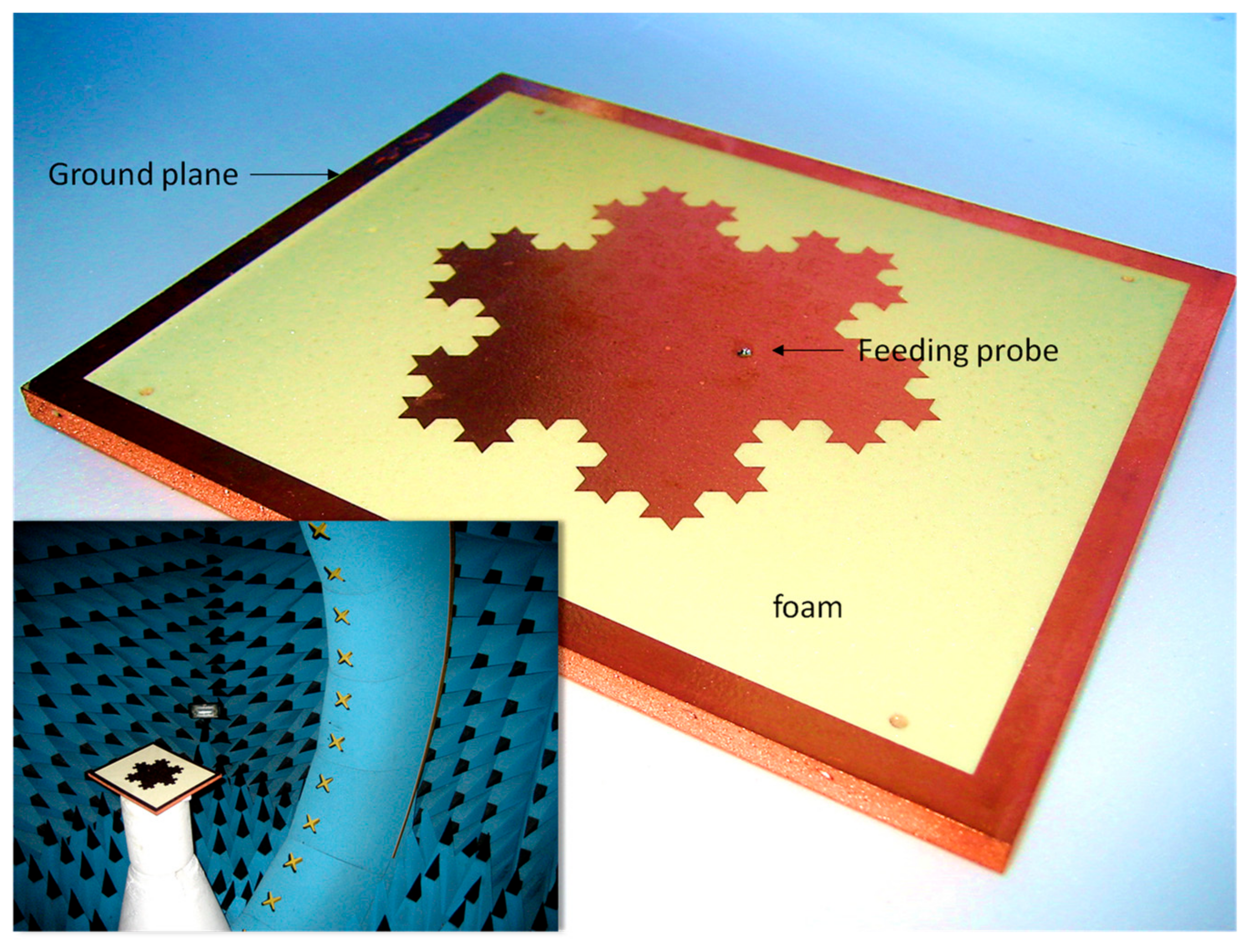
- Anguera, J.; Daniel, J.P.; Borja, C.; Mumbrú, J.; Puente, C.; Leduc, T.; Laeveren, N.; van Roy, P. On the behavior of the Koch Island Fractal-Shaped Microstrip Patch Antenna etched on a Metallized Foam. In Proceedings of the IEEE Antennas and Propagation Society International Symposium, San Diego, CA, USA, 5–11 July 2008. [Google Scholar]
- Anguera, J.; Puente, C.; Borja, C. Miniature Broadband Ring-Like Microstrip Patch Antenna. U.S. Patent 6,870,507 B2, 22 March 2005. [Google Scholar]
- Puente, C.; Romeu, J.; Cardama, A. The Koch monopole: A small fractal antenna. IEEE Trans. Antennas and Propag. 2000, 48, 1773–1781. [Google Scholar]
- Puente, C.; Romeu, J.; Pous, R.; Ramis, J.; Hijazo, A. Small but long Koch fractal monopole. Electron. Lett. 1998, 34, 9–10. [Google Scholar] [CrossRef] [Green Version]
- Anguera, J.; Puente, C.; Martínez, E.; Rozan, E. The fractal Hilbert monopole: A two-dimensional wire. Microw. Optical Technol. Lett. 2003, 36, 102–104. [Google Scholar] [CrossRef]
- Farswan, A.; Gautam, A.K.; Kanaujia, B.K.; Rambabu, K. Design of Koch fractal circularly polarized antenna for handheld UHF RFID reader applications. IEEE Trans. Antennas Propag. 2015, 64, 771–775. [Google Scholar] [CrossRef]
- Yaziz, N.S.M.; Rahim, M.K.A.; Zubir, F.; Nadzir, N.S.; Dewan, R.; Majid, H.A. The Improvement of First Iteration Log Periodic Fractal Koch Antenna with Slot Implementation. Int. J. Electr. Comput. Eng. 2018, 8, 2564. [Google Scholar]
- Choukiker, Y.K.; Behera, S.K. Wideband frequency reconfigurable Koch snowflake fractal antenna. IET Microw. Antennas Propag. 2017, 11, 203–208. [Google Scholar] [CrossRef]
- Rahman, N.A.A.; Jamlos, M.F.; Lago, H.; Jamlos, M.A.; Soh, P.J.; Al-Hadi, A.A. Reduced size of slotted-fractal Koch log-periodic antenna for 802.11 TVWS application. Microw. Opt. Technol. Lett. 2015, 57, 2732–2737. [Google Scholar] [CrossRef]
- Yaziz, N.S.M.; Rahim, M.K.A.; Zubir, F.; Murad, N.A. Series iteration of Fractal Koch antenna at UHF band. In Proceedings of the 2016 10th European Conference on Antennas and Propagation (EuCAP), Davos, Switzerland, 10–15 April 2016; pp. 1–4. [Google Scholar]
- Rajabloo, H.; Kooshki, V.A.; Oraizi, H. Compact microstrip fractal Koch slot antenna with ELC coupling load for triple band application. AEU-Int. J. Electron. Commun. 2017, 73, 144–149. [Google Scholar] [CrossRef]
- Hebelka, V.; Velim, J.; Raida, Z. Dual band Koch antenna for RF energy harvesting. In Proceedings of the 2016 10th European Conference on Antennas and Propagation (EuCAP), Davos, Switzerland, 10–15 April 2016; pp. 1–3. [Google Scholar]
- Gupta, M.; Mathur, V. Koch boundary on the square patch microstrip antenna for ultra wideband applications. Alex. Eng. J. 2018, 57, 2113–2122. [Google Scholar] [CrossRef]
- Ye, R.; Liu, L. An Iterated Function System based Method to Generate Hilbert-type Space-filling Curves. Int. J. Inf. Technol. Comput. Sci. 2015, 12, 12–22. [Google Scholar] [CrossRef]
- Gala, D.; Soler, J.; Puente, C.; Borja, C.; Anguera, J. Miniature Microstrip Patch Antenna Loaded with a Space-Filling Line Based on the Fractal Hilbert Curve. Microw. Opt. Technol. Lett. 2003, 38, 311–312. [Google Scholar] [CrossRef]
- Anguera, J.; Puente, C.; Soler, J. Miniature Monopole Antenna based on the Fractal Hilbert Curve. IEEE Antennas Propag. Soc. Int. Symp. 2002, 4, 546–549. [Google Scholar]
- Azad, M.Z.; Ali, M. A miniaturized Hilbert PIFA for dual-band mobile wireless applications. IEEE Antennas Wirel. Propag. Lett. 2005, 4, 59–62. [Google Scholar] [CrossRef] [Green Version]
- Azaro, R.; Viani, F.; Lizzi, L.; Zeni, E.; Massa, A. A Monopolar Quad-Band Antenna Based on a Hilbert Self-Affine Prefractal Geometry. IEEE Antennas Wirel. Propag. Lett. 2009, 8, 177–180. [Google Scholar] [CrossRef] [Green Version]
- Baliarda, C.P.; Rozan, E.J.L.; Anguera, J. Space-Filling Miniature Antennas. U.S. Patent 7,202,822, 10 April 2007. [Google Scholar]
- Sanz, I.; Anguera, J.; Andújar, A.; Puente, C.; Borja, C. The Hilbert Monopole Revisited. In European Conference on Antennas and Propagation; EuCAP: Barcelona, Spain, 2010. [Google Scholar]
- Bangi, I.S.; Sivia, J.S. Minkowski and Hilbert curves-based hybrid fractal antenna for wireless applications. AEU-Int. J. Electron. Commun. 2018, 85, 159–168. [Google Scholar] [CrossRef]
- Saputro, S.A.; Chung, J.Y. Hilbert curve fractal antenna for dual on-and off-body communication. Prog. Electromagn. Res. 2016, 58, 81–88. [Google Scholar] [CrossRef] [Green Version]
- Krim, K.; Abri, M.; Badaoui, H.; Fersiti, S.; Mahieddine, F. New Design of a Microstrip-Fed Printed Slot UWB Antenna with Hilbert Fractal Defected Ground Structure. In Third International Conference on Computing and Wireless Communication Systems; European Alliance for Innovation (EAI): Ghent, Belgium, 2019. [Google Scholar]
- Roushdy, M.M.; Hammad, H.F. Inkjet printed wearable Hilbert monopole fractal antenna optimized for BAN systems. In Proceedings of the 2016 33rd National Radio Science Conference (NRSC), Aswan, Egypt, 22–25 January 2016; pp. 102–108. [Google Scholar]
- McVay, J.; Engheta, N.; Hoorfar, A. High-impedance metamaterial surfaces using Hilbert-curve inclusions. IEEE Microw. Wirel. Comp. Lett. 2004, 14, 130–132. [Google Scholar] [CrossRef] [Green Version]
- McVay, J.; Engheta, N.; Hoorfar, A. Numerical study and parameter estimation for double-negative metamaterials with Hilbert-curve inclusions. In Proceedings of the 2005 IEEE Antennas and Propagation Society International Symposium, Washington, DC, USA, 3–8 July 2005; Volume 2, pp. 328–331. [Google Scholar]
- Yousefi, L.; Ramahi, O.M. Artificial Magnetic Materials Using Fractal Hilbert Curves. IEEE Trans. Antennas Propag. 2010, 58, 2614–2622. [Google Scholar] [CrossRef]
- Manimegalai, B.; Raju, S.; Abhaikumar, V. A Multifractal Cantor Antenna for Multiband Wireless Applications. IEEE Antennas Wirel. Propag. Lett. 2009, 8, 359–362. [Google Scholar] [CrossRef]
- Hebib, S.; Raveu, N.; Aubert, H. Cantor Spiral Array for the Design of Thinned Arrays. IEEE Antennas Wirel. Propag. Lett. 2006, 5, 104–106. [Google Scholar] [CrossRef] [Green Version]
- Bakytbekov, A.; Maza, A.R.; Nafe, M.; Shamim, A. Fully inkjet printed wide band cantor fractal antenna for RF energy harvesting application. In Proceedings of the 2017 11th European Conference on Antennas and Propagation (EUCAP), Paris, France, 19–24 March 2017; pp. 489–491. [Google Scholar]
- Dhar, S.; Patra, K.; Ghatak, R.; Gupta, B.; Poddar, D.R. A Dielectric Resonator-Loaded Minkowski Fractal-Shaped Slot Loop Heptaband Antenna. IEEE Trans. Antennas Propag. 2015, 63, 1521–1529. [Google Scholar] [CrossRef]
- Dhar, S.; Ghatak, R.; Gupta, B.; Poddar, D.R. A Wideband Minkowski Fractal Dielectric Resonator Antenna. IEEE Trans. Antennas Propag. 2013, 61, 2895–2903. [Google Scholar] [CrossRef]
- Comisso, M. Theoretical and numerical analysis of the resonant behaviour of the Minkowski fractal dipole antenna. IET Microw. Antennas Propag. 2019, 3, 456–464. [Google Scholar] [CrossRef]
- Vinoy, K.J.; Pal, A. Dual-frequency characteristics of Minkowski-square ring antennas. IET Microw. Antennas Propag. 2010, 4, 219–224. [Google Scholar] [CrossRef] [Green Version]
- Li, Y.; Li, L.; Zhang, Y.; Zhao, C. Design and Synthesis of Multilayer Frequency Selective Surface Based on Antenna-Filter-Antenna Using Minkowski Fractal Structures. IEEE Trans. Antennas Propag. 2015, 63, 133–141. [Google Scholar] [CrossRef]
- Zhang, X.; Wu, W.; Huang, L.; Ma, Y.; Yuan, N. Design of Dual Absorptive Bands Frequency Selective Rasorber with Minkowski Loop Arrays. IEEE Antennas Wirel. Propag. Lett. 2019, 18, 1843–1847. [Google Scholar] [CrossRef]
- Kubacki, R.; Czyzewski, M.; Laskowski, D. Minkowski Island and Crossbar Fractal Microstrip Antennas for Broadband Applications. Appl. Sci. 2018, 8, 334. [Google Scholar] [CrossRef] [Green Version]
- Cao, T.N.; Krzysztofik, W.J. A Novel Design for Compact Multi-Band Antenna Based on Fractal Geometry and Metamaterials. In Proceedings of the 2019 IEEE European Microwave Conference in Central Europe (EuMCE), Prague, Czech Republic, 13–15 May 2019; pp. 171–174. [Google Scholar]
- Alibakhshikenari, M.; Virdee, B.S.; See, C.H.; Abd-Alhameed, R.; Ali, A.H.; Falcone, F.; Limiti, E. Study on isolation improvement between closely-packed patch antenna arrays based on fractal metamaterial electromagnetic bandgap structures. IET Microw. Antennas Propag. 2018, 12, 2241–2247. [Google Scholar] [CrossRef] [Green Version]
- Zarifi, D.; Soleimani, M.; Nayyeri, V.; Rashed-Mohassel, J. On the miniaturization of semiplanar chiral metamaterial structures. IEEE Trans. Antennas Propag. 2012, 60, 5768–5776. [Google Scholar] [CrossRef]
- Amiri, M.; Tofigh, F.; Shariati, N.; Lipman, J.; Abolhasan, M. Miniature tri-wideband Sierpinski–Minkowski fractals metamaterial perfect absorber. IET Microw. Antennas Propag. 2019, 13, 991–996. [Google Scholar] [CrossRef]
- El-Khouly, E.; Ghali, H.; Khamis, S.A. High Directivity Antenna Using a Modified Peano Space-Filling Curve. IEEE Antennas Wirel. Propag. Lett. 2007, 6, 405–407. [Google Scholar] [CrossRef]
- McVay, J.; Hoorfar, A. Miniaturization of top-loaded monopole antennas using Peano-curves. In Proceedings of the 2007 IEEE Radio and Wireless Symposium, Long Beach, CA, USA, 9–11 January 2007; pp. 253–256. [Google Scholar]
- Oraizi, H.; Hedayati, S. Miniaturized UWB Monopole Microstrip Antenna Design by the Combination of Giusepe Peano and Sierpinski Carpet Fractals. IEEE Antennas Wirel. Propag. Lett. 2011, 10, 67–70. [Google Scholar] [CrossRef]
- Werner, D.H.; Kuhirun, W.; Werner, P.L. The Peano-Gosper fractal array. IEEE Trans. Antennas Propag. 2003, 51, 2063–2072. [Google Scholar] [CrossRef]
- Zhu, J.; Hoorfar, A.; Engheta, N. Peano antennas. IEEE Antennas Wirel. Propag. Lett. 2004, 3, 71–74. [Google Scholar]
- Da Silva, M.R.; Nobrega, C.D.; Silva, P.H.D.; D’Assuncao, A.G. Stable and compact multiband frequency selective surfaces with Peano pre-fractal configurations. IET Microw. Antennas Propag. 2013, 7, 543–551. [Google Scholar] [CrossRef]
- Oraizi, H.; Hedayati, S. Miniaturization of Microstrip Antennas by the Novel Application of the Giuseppe Peano Fractal Geometries. IEEE Trans. Antennas Propag. 2012, 60, 3559–3567. [Google Scholar] [CrossRef]
- Sharma, N.; Singh, G.P.; Sharma, V. Miniaturization of fractal antenna using novel Giuseppe Peano geometry for wireless applications. In Proceedings of the 2016 IEEE 1st International Conference on Power Electronics, Intelligent Control and Energy Systems (ICPEICES), Delhi, India, 4–6 July 2016; pp. 1–4. [Google Scholar]
- Vegesna, N.; Yugandhar, K.; Bharathi, D.V.; KrishnaKanth, V. Giuseppe Peano Fractal Antenna for Application in X to KA Bands. J. Comput. Theor. Nanosci. 2019, 16, 1284–1288. [Google Scholar] [CrossRef]
- Singh, G.P.; Sharma, N. Novel Design of Fractal Antenna using Giuseppe Peano Geometry for Wireless Applications. Int. J. Comput. Appl. 2016, 150, 975–8887. [Google Scholar]
- Goyal, A.; Alphones, A.; Karim, M.F.; Ong, C.L. A compact monopole fractal antenna for TV white space energy harvesting applications. In Proceedings of the 2015 IEEE International Symposium on Antennas and Propagation & USNC/URSI National Radio Science Meeting, Vancouver, BC, Canada, 19–24 July 2015; pp. 2437–2438. [Google Scholar]


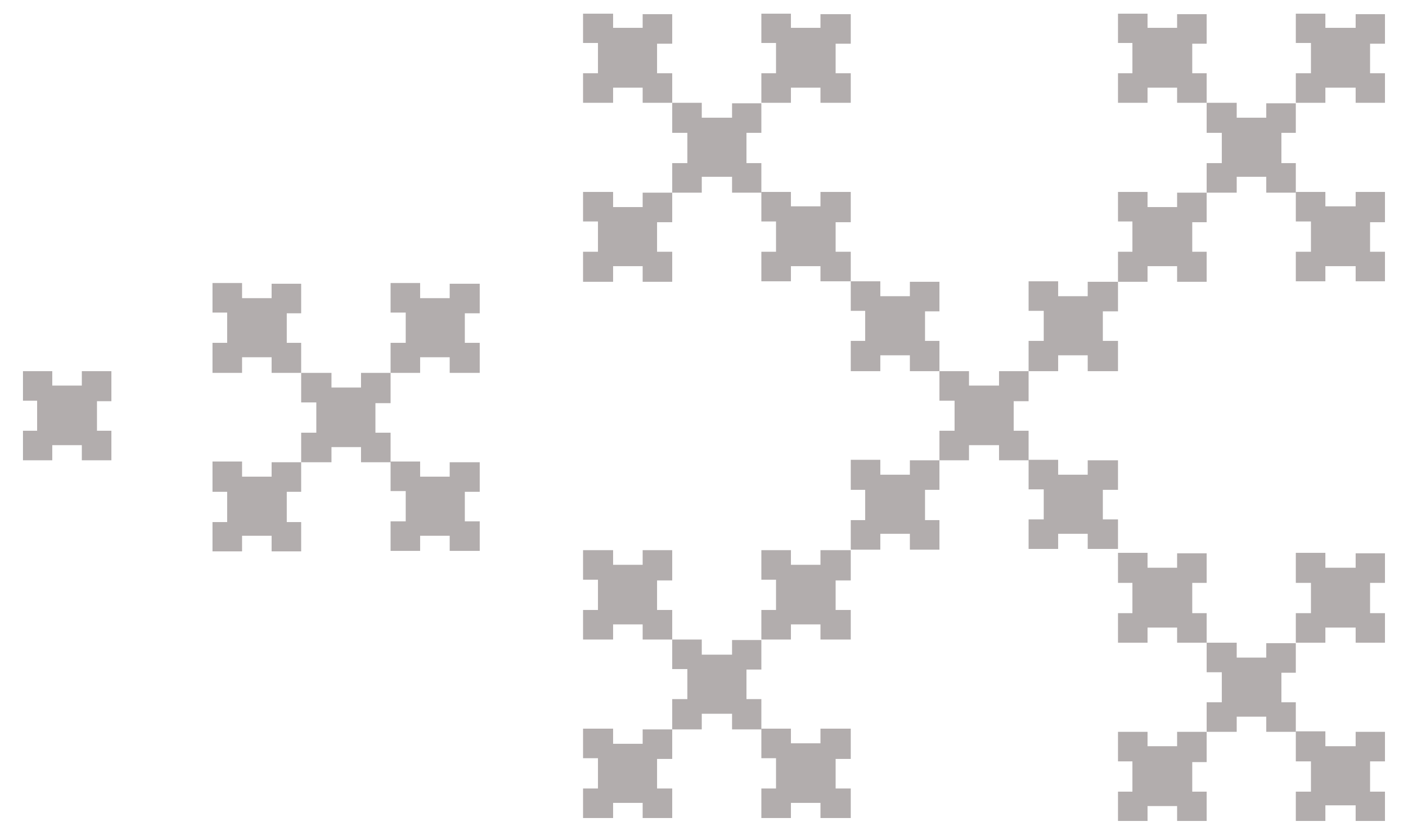
| IFS to Generate the Koch Island Based on Seven Affine Linear Transformations | |
|---|---|
 | |
© 2020 by the authors. Licensee MDPI, Basel, Switzerland. This article is an open access article distributed under the terms and conditions of the Creative Commons Attribution (CC BY) license (http://creativecommons.org/licenses/by/4.0/).
Share and Cite
Anguera, J.; Andújar, A.; Jayasinghe, J.; Chakravarthy, V.V.S.S.S.; Chowdary, P.S.R.; Pijoan, J.L.; Ali, T.; Cattani, C. Fractal Antennas: An Historical Perspective. Fractal Fract. 2020, 4, 3. https://doi.org/10.3390/fractalfract4010003
Anguera J, Andújar A, Jayasinghe J, Chakravarthy VVSSS, Chowdary PSR, Pijoan JL, Ali T, Cattani C. Fractal Antennas: An Historical Perspective. Fractal and Fractional. 2020; 4(1):3. https://doi.org/10.3390/fractalfract4010003
Chicago/Turabian StyleAnguera, Jaume, Aurora Andújar, Jeevani Jayasinghe, V. V. S. S. Sameer Chakravarthy, P. S. R. Chowdary, Joan L. Pijoan, Tanweer Ali, and Carlo Cattani. 2020. "Fractal Antennas: An Historical Perspective" Fractal and Fractional 4, no. 1: 3. https://doi.org/10.3390/fractalfract4010003