1. Introduction
Improving the efficiency of gas turbines has long been recognized as crucial due to their significant economic advantages in the fields of aviation and power generation. To achieve enhanced efficiency and a reduced carbon footprint, it is imperative to improve the materials, design, and working boundary conditions of gas turbines. The current manual process of optimizing high-pressure turbine blades to enhance cooling is both intricate and time-consuming. To address this challenge, an automation framework is proposed in this study to automate the design, meshing, and structural analysis of cooling channels in high-pressure turbine blades.
The need for gas turbines in the global market is projected to increase at a compound annual growth rate of 3.3% [
1]. To meet the global demand for durable and energy-efficient gas turbines, there is a need to overcome the challenges of evaluating their life cycle. This complexity arises from the intricate interplay between turbine blades and dynamic factors such as fluctuating temperatures, thermal stresses, diverse boundary conditions, etc. This study proposes reducing the time required in the development phase of a turbine blade cooling channel by implementing strategies such as design automation (DA) along with automation of meshing and structural analysis.
Modern gas turbines have an inlet temperature of 2000 K, which is far higher than the melting point of all materials used for turbine blades [
2]. In order to ensure blade integrity and achieve an extended operational lifespan, different cooling methodologies are employed. This paper considers the automation of the design and simulation of a single-pass cooling geometry with pin-fins, turbulence promoters, and holes for film cooling. The primary objective of this project is to create an automated process for design and structural analysis using knowledge-based engineering (KBE) for the evaluation of the lifetime of the blade and to enable a seamless multidisciplinary design framework to evaluate various characteristics of the blade. This work encompasses advancements in the DA of turbine blade cooling channels, specifically focusing on achieving a higher level of morphological automation. Additionally, this study addresses the need for topological automation, which can be applied to various configurations and models of turbine vanes. By adopting a generic approach, the proposed method enhances its versatility and potential integration with thermal, fluid, and structural analyses, facilitating a comprehensive analysis of turbine systems.
2. Related Work and State of the Art
Cooling design in a turbine blade is a multidisciplinary, iterative, and labor-intensive process. The designers involved in such development are required to possess a broad spectrum of knowledge spanning various domains, including structural analysis, thermodynamics, and fluid dynamics. Given the complexities of the product and the need for detailed output, each domain necessitates management and evaluation by specific domain experts. In theory, the size of the knowledge base in engineering companies has never been bigger. This is primarily due to the increasing volume of data and models generated through various engineering tools.
According to Chapman and Pinfold (2001) [
3], a complex engineering product has to be treated as a complete system instead of developing each subsystem independently. It is therefore necessary to combine models from several disciplines to achieve the optimal design of an entire system rather than designing its subsystems in a sub-optimal manner. Multidisciplinary optimization (MDO) is a promising method for managing sub-system cross-couplings and for treating products holistically. In order to enable MDO, all design and evaluation processes of the product need to be integrated and automated. The level of the DA will be a crucial defining factor for the design space of the product.
2.1. Design Automation
Engineering design automation is a field of wide range of design-related tasks comprising various methodologies and applications in different industries [
4]. According to Cederfeldt and Elgh, the term DA is defined as the “computerized automation of tasks that are related to the design process through the implementation of information and knowledge in tools and systems”. Moreover, DA is possible at many degrees of complexity, from the usage of family template systems or predetermined machine parts to knowledge-intensive CAD systems or extremely complex KBE systems [
5]. The automation of the design process and design object have been areas of research within the subject of DA [
6]. While designing a customized product, a requirement is the creation of a detailed description of the specific processing steps required throughout the design process [
7]. A DA framework can be developed using this knowledge in the design process to automate tedious and repetitive tasks, thereby allowing the designers to focus more on the operations that require creativity, intuition, skill, and cooperation to be solved [
8].
The motivation for DA can differ widely. The ability to save costs, shorten lead times, enhance product performance and modify products to meet customer requirements are four key broad goals of DA. Gaining an effective and efficient product development process is the main driver behind the implementation of DA [
4]. According to Cederfeldt, the most important benefit of implementing a DA framework is the quality assurance in the final output [
9]. While the input to a DA framework can be customer requirements, parametric constraints, geometric models, design variables, etc., outputs can be geometric models, physical properties, or even manufacturing plans [
10]. Similar to other systems, an efficient DA framework/system should be able to adapt to different requirements within its operational environment. With high adaptability, as mentioned earlier, the efficiency and effectiveness of a product will increase with a high level of maintainability [
11].
2.1.1. Knowledge-Based Engineering
Craig and Pinfold [
3] define knowledge-based engineering (KBE) as an engineering method representing CAD technologies, object-oriented programming, and artificial intelligence. Through the collection, capture, transformation, retention, and re-use of product and process knowledge, KBE accelerates the creation of new products by automating repetitive design activities [
12]. Automating repetitive operations using a knowledge-based system (KBS) is the primary goal of KBE. In the KBE approach, a user’s knowledge of the environment/product is stored, and it is made available permanently. The KBS consists of two segments, called a knowledge base and an interface engine, to form an interface to implement KBE. The division of the knowledge base and the functions that use it, known as the interface engine, is one of the KBS’s defining characteristics [
13]. The DA framework can be maintained more quickly and effectively because of this separation of the interface engine and knowledge base, which enables future knowledge base updates without compromising the interface engine [
8].
The knowledge base is made up of rules, relations, and facts and is not stored sequentially since it must be executed. As a tool, the interface engine makes use of the knowledge kept in the knowledge base. Two of the most prevalent forms of interface engines used to activate the knowledge base are forward chaining and backward chaining [
13]. The rules that satisfy the stated criterion are located and put into action in the forward-chaining interface. The guidelines are then spelled out, enumerated, and implemented until the desired results are obtained. A backward-chaining interface, on the other hand, is a goal-oriented interface in which the interface engine looks for rules that results in the final output and is then sent back to the interface engine to be executed to acquire the desired result.
2.1.2. Geometry Transformation
An efficient DA framework requires a comprehensive knowledge base with flexible and robust CAD models to achieve effective geometry transformations. This study identifies two main categories of transformations: morphological transformation and topological transformation.
Morphological transformation involves altering the form or shape of CAD models. The complexity of designs determines the morphological levels at which CAD models can be categorized. These levels can be visualized as a pyramid, with the first level representing fixed objects that cannot change their shape. Parameterized CAD models reside at the second level, allowing for limited flexibility by adjusting geometric values. For more intricate geometries, the third level incorporates parameters, relations, and rules among the model’s geometric elements. CAD models that enable control of parameters, rules, and relations using programming languages occupy the top of the morphological transformation pyramid [
14].
Similarly, topological transformation involves changing the position or location of models. As with morphological transformation, topological transformation can be categorized into four levels. The levels of topological transformation consist of manual instantiation, automatic instantiation, generic manual instantiation, and generic automatic instantiation. The ultimate goal is to attain a high level of topological transformation by developing high-level CAD templates for various elements within a turbine vane cooling system and implementing an automatic and generic instantiation approach.
2.2. Design Automation of Turbine Blade
Considerable research has been conducted over the years in the optimization of cooling structures in a turbine blade. Chi et al. [
15] presented a multi-dimensional platform for the design of cooling structures in air-cooled turbine blades, which gives an overview of the transmission of data between different platforms to perform DA and MDO. An algorithm to create parametric designs for cooling channels is introduced into this framework, enabling a more accessible knowledge base. However, not all processes are automated, which leads to a semi-automatic framework that is not suitable for an MDO process. Usually, the frameworks are built in a case-specific manner, being available only for a particular cooling structure.The focus of such research is concentrated on the individual performances comprising the overall efficiency of the turbine blade. Lu et al. [
16], Chi et al. [
17], and Yeranee et al. [
18] developed a state-of-the-art framework to perform optimization on specific cooling structures, such as film cooling holes, ribs, and pin-fin cooling structures, respectively. Lu et al. [
16] show the successful integration of interdisciplinary software to perform automatic geometry and mesh generation. Although the proposed model is parametric, the number of film cooling holes is kept constant during the optimization. There is also a lack of transparency in how the mesh automation is handled. Chi et al. [
17] performed a Computational Heat Transfer (CHT) optimization for the internal blade design to find the optimal rib arrangement with better cooling efficiency. Moreover, Yeranee et al. [
18] present a method of density-based topology optimization to enhance the thermal performance of a pin-fin cooling structure. Xu et al. [
19] present a methodology to perform an optimization of lattice structures in a gas turbine blade for heat transfer and mechanical performances. Similar to this, Ghosh et al. [
20] explain a computationally efficient approach involving Gaussian processes, surrogate modeling and constrained Bayesian optimization of pin-fin arrays. The modeling is performed entirely in CFD software, resulting in a compromise in flexibility in the DA with the benefit of faster processing time. Xiaodong and Xiuli [
21] performed multidisciplinary automation for design and mesh for an optimization process. Unlike other research, the focus in this case is also on the successful transfer of data or knowledge between different platforms. A module specific for static, fluid, and thermal is present in the framework to perform corresponding calculations. Similarly, Zhang et al. [
22] developed a framework for performing multidisciplinary calculations on a twin-web turbine disk, which includes an integrated system for evaluating different disciplines.
The crucial property to estimate while designing and developing turbine blades is the life cycle. Along with mechanical and thermal performances, the work life of a component is of the utmost importance. Performing an optimization with a focus on the product life cycle is often neglected or, in most cases, performed separately, considering only the working environment or boundary conditions as the design of experiments. However, a turbine blade optimized for an extended life cycle considering its thermal and mechanical performance for variable geometrical parameters and boundary conditions is an area of peak interest in the current industry. Li et al. [
23] present a reliability-based multidisciplinary design optimization for heat transfer with corresponding life prediction. A morphological parameterized model is used to initialize the surrogate model to perform MDO.
A study has been conducted in the area of multidisciplinary automation for the development of turbine blades, cooling channels, turbine disks, etc. A common set of characteristics is tabulated as shown in
Table 1 to find out the research with the most similarity and evaluate the research gap in this field. The research by Xiaodong and Xiuli focuses on multidisciplinary design optimization of turbine disks using different platforms [
21]. However, the model lacks topological parametrization and its corresponding automation sequence, along with a module for life cycle evaluation. A generic approach with a high-level CAD template integrated with automated design allows for geometric alterations, such as the shape of the elements (morphology) as well as number of elements (topology) [
24]. A similar automation method to that of Tarkian [
24], but customized to perform generic operations irrespective of the templates, which can perform multidisciplinary evaluations, will be a much-needed off-the-shelf framework for the turbine development process.
2.3. Finite Element Analysis
Finite element analysis is a numerical approach that is used for a variety of numerical analyses, including those of fluid flow, heat transfer, electric and magnetic fields, and many others [
31]. The complexity of the issues, including their varied shapes, boundary conditions, and loads, are all retained in this approach, but the results are approximate. In the finite element technique, a given domain is considered a collection of subdomains, and the governing equation is estimated across each subdomain using any applicable variational method, including the more conventional ones.
Meshing
The process of breaking down a continuous geometric model into multiple shapes or sets of sub-domains to define the physical shape of an object is called meshing. This is one of the primary steps in the simulation of a geometric model, which defines the accuracy of the final simulated output [
32]. However, this process can often be time-consuming and iterative, in some cases. Hence, it is crucial to use a robust, practical, and adaptable finite element pre-processing tool that can interchange data with several CAD systems and finite element solvers in order to increase the effectiveness and quality of finite element analysis. Meshes are generally categorized into two types: structured and unstructured mesh. Unstructured mesh connects elements using erratic patterns, which are used to capture complicated geometric shapes, while structured mesh uses regular lattice to link neighboring nodes.
3. Methodology
This work presents the proof-of-concept of a framework for multidisciplinary automation of design, meshing, and FEA for the development and analysis of cooling channels in a turbine vane. One of the biggest challenges of automation in the gas turbine industry is the involvement of different applications, which makes cross-platform automation with data transfer between these applications and sequencing the execution of operations extremely difficult. The results of this study will validate a novel approach for conducting multidisciplinary automation that can handle both morphological and topological changes.
The ultimate aim of this project is to develop a multidisciplinary optimization framework using KBE to investigate performance factors such as cooling efficiency, thermo-mechanical fatigue, and life cycle. This paper focuses on the development of a multidisciplinary automation framework that involves DA, mesh automation, and a simple finite element analysis.
Figure 1 shows the automation architecture for the project, which aims to lay the foundation for multidisciplinary optimization (MDO) to achieve the optimum design within the design space. Different software, such as Siemens NX [
33], Hypermesh [
34], and Abaqus [
35], are used for CAD automation, meshing, and FEA, respectively. All of these programs have two-way communication with a database module that can read and write data from them. Since the database module is continuously updated throughout the process, a user interface is included in the framework, enabling the user to change different properties, parameters, assembly instructions, meshing inputs, boundary conditions, etc. Separation of the user interface and database improves the re-usability of the model with ease of maintenance and updates.
As shown in
Figure 1, the implemented framework connects three software. Based on the user (or optimization) input, the DA part is handled in the CAD tool. Here, a new design with a custom blade and cooling design is created. The new design is fed into a meshing tool, where custom settings for different design features in the model are added based on user preferences read from the database. A finite element analysis is performed, where boundary conditions are automatically applied and adapted based on the custom design. During this process, the inference engine controls the process of calling the software as well as reading and writing information to the database where knowledge is stored. In addition to the already-implemented software, the framework is also prepared to connect to models for the simulation of cooling, fatigue, and life cycle evaluation. However, this is not utilized in this version of the framework.
3.1. Design Automation
The development of CAD automation can be divided into three stages. The first stage is the research phase, which involves background studies regarding the different components, cooling methods, and processes of data transfer between different software. With the acquired knowledge, the second phase is started, which includes setting up of the communication between CAD tool and the database module with the help of an interface engine. In order to develop a reusable and generic automation framework in NX, both NX Open and Journal programming features were investigated. NX Open is a programming tool in NX, which is a collection of APIs allowing for the creation of custom applications that can be executed through NX. This is a useful feature for packaging multiple scripts supporting commonly used programming languages (C/C++, Visual Basic, C#, Java, and Python) and allows the transfer of data to third-party software with the addition of some external APIs. Journal programming is a feature within NX that requires no setup or extra licensing. A journal editor can be used to run the recorded macros in the NX, which can be in any programming language supported by NX Open.
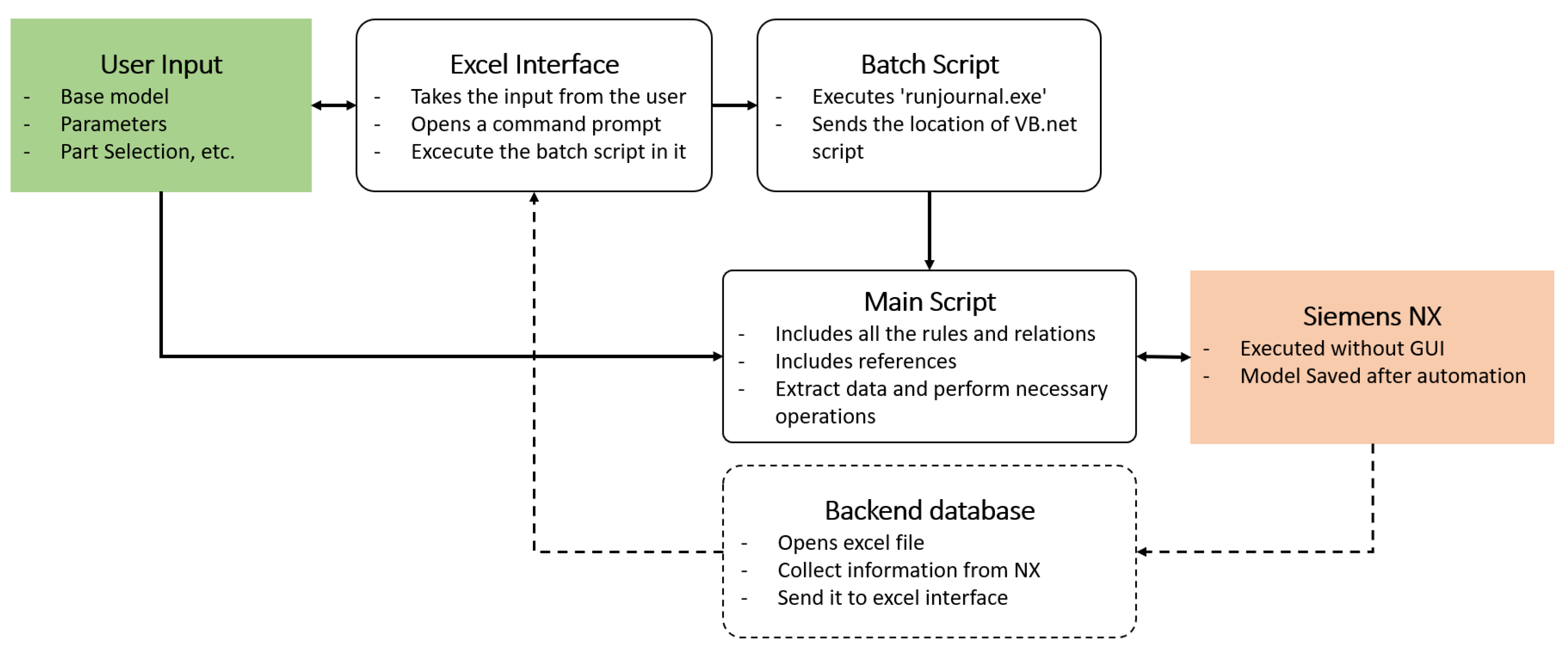
Between NX Open and Journal, the latter is selected for the primary coding since it can be executed outside of NX using BATCH scripts and external applications (RunJournal.exe) for the journal execution. One of the biggest challenges in this study was to establish two-way communication with NX and a third-party software since the entire product development process needs to be monitored for the upcoming part of the project (MDO). The flowchart shown in
Figure 2 is the simplified working architecture of the DA setup in NX. The first step was to acquire some user inputs, such as the location and name of turbine vane outer geometry, along with the templates required to instantiate User Defined Features (UDF) and geometric parameters. The number of parameters in this user interface can vary depending on the user’s selection of UDFs. The parameter list includes the type of UDF model along with data to bring about changes at both topological and morphological levels.
There is a two-way communication between the user interface and the Excel interface, where data from the user are transferred to the Excel workbook while the finished results and output data are fed back into the user interface for the visualization and evaluation process. The macro inside the Excel workbook opens a command prompt with the location of the batch script as an argument. The batch script has a function to call for an application called ’run_journal.exe’ and the location of the main script or journal as the argument. While using ’run_journal’, NX runs in batch mode with no graphical user interface (GUI). The main script contains all the rules, relations, assembly instructions, and code for the instantiation of UDFs on the base model shown in
Figure 3. While creating a UDF, information such as reference details, input requirements, expression lists, etc. can be easily documented in a text file, which is later accessed to collect the required data on the user-specified parts. Once the base model is opened, information regarding all the features, the type of feature, and its IDs are added to a back-end Excel database so that the required information for meshing or optimization (later) can be filtered out from this.
DA in CAD software is executed in headless mode; hence, the results are automatically saved at a location mentioned in the main script for later use as well as for visualization. Because of compatibility issues between CAD and the meshing tool, the DA results are saved in ’.prt’ as well as in the Parasolid file format. While the automation process is ongoing, some of the information mentioned above is transferred back into the Excel interface by passing through a back-end database. This allows for complex data handling while preserving the data for the next stage in the cycle, as shown in
Figure 1.
3.2. Mesh Automation and Simulation
The meshing operation required to perform a structural analysis in this project is executed using the Hypermesh software [
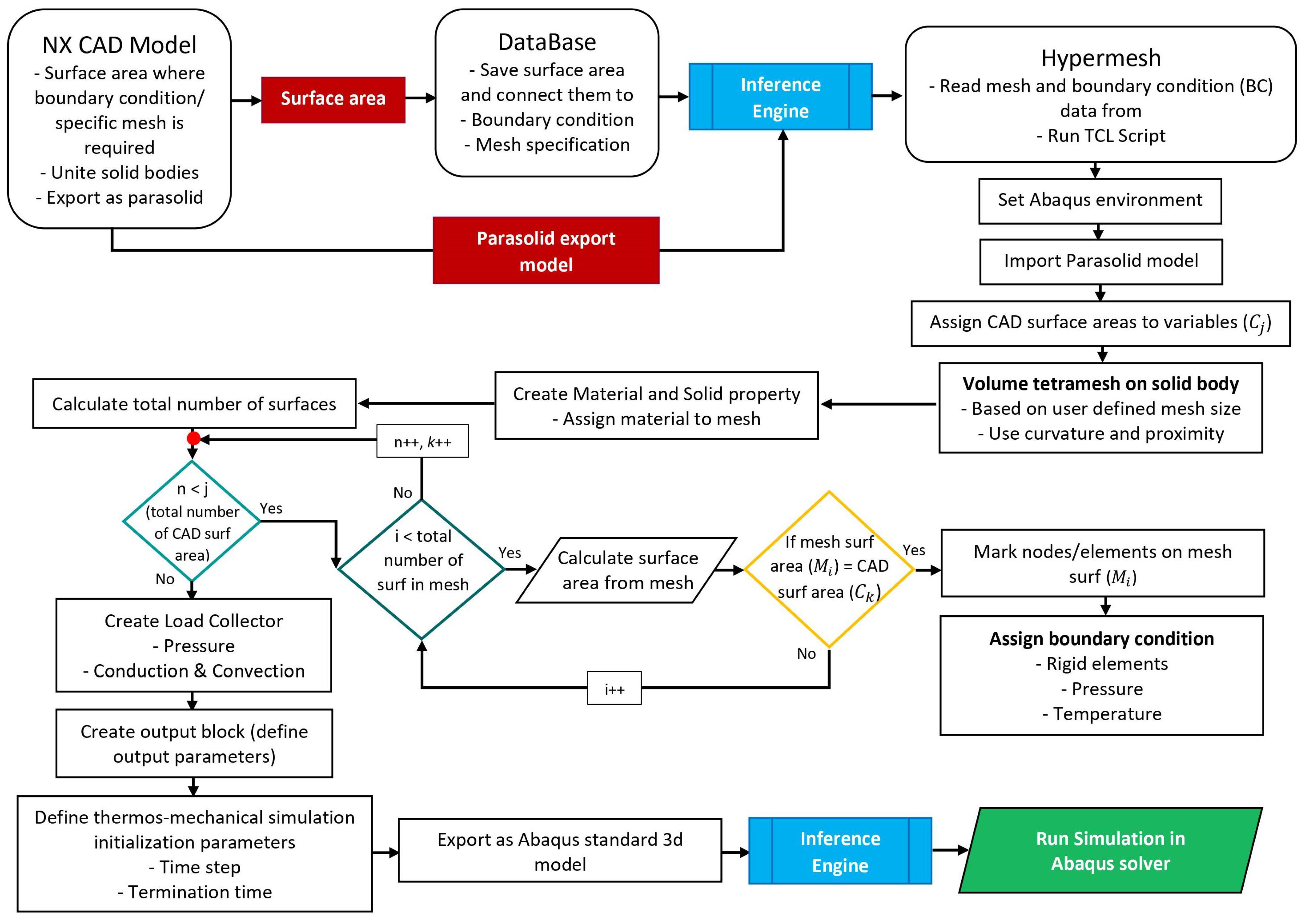
34]. This software allows for high-level functions such as automatic mesh generation by removing the need for manual geometry cleanup and meshing, hence speeding up the model development process. The structural analysis is performed in the FEA solver, and, later, the simulation results are exported. To run simulation models created by third-party programs, the selected FEA tool has a dedicated solver terminal that can be called independently. The framework developed to automate meshing and simulation is shown in
Figure 4. Once the design is automated from the NX, the individual solid bodies are united for the ease of the meshing process. Later, this model is saved as a parasolid with the necessary information, such as surface names, surface area, etc., passed to the back-end database. The back-end database shown in
Figure 4 is the same as the one shown in
Figure 2. These data are accessible for the Excel interface to showcase to the user while inputting the boundary conditions for the simulations along with other details such as mesh size and type. Excel will run the batch script to operate the meshing software using the TCL script to automate the meshing process.
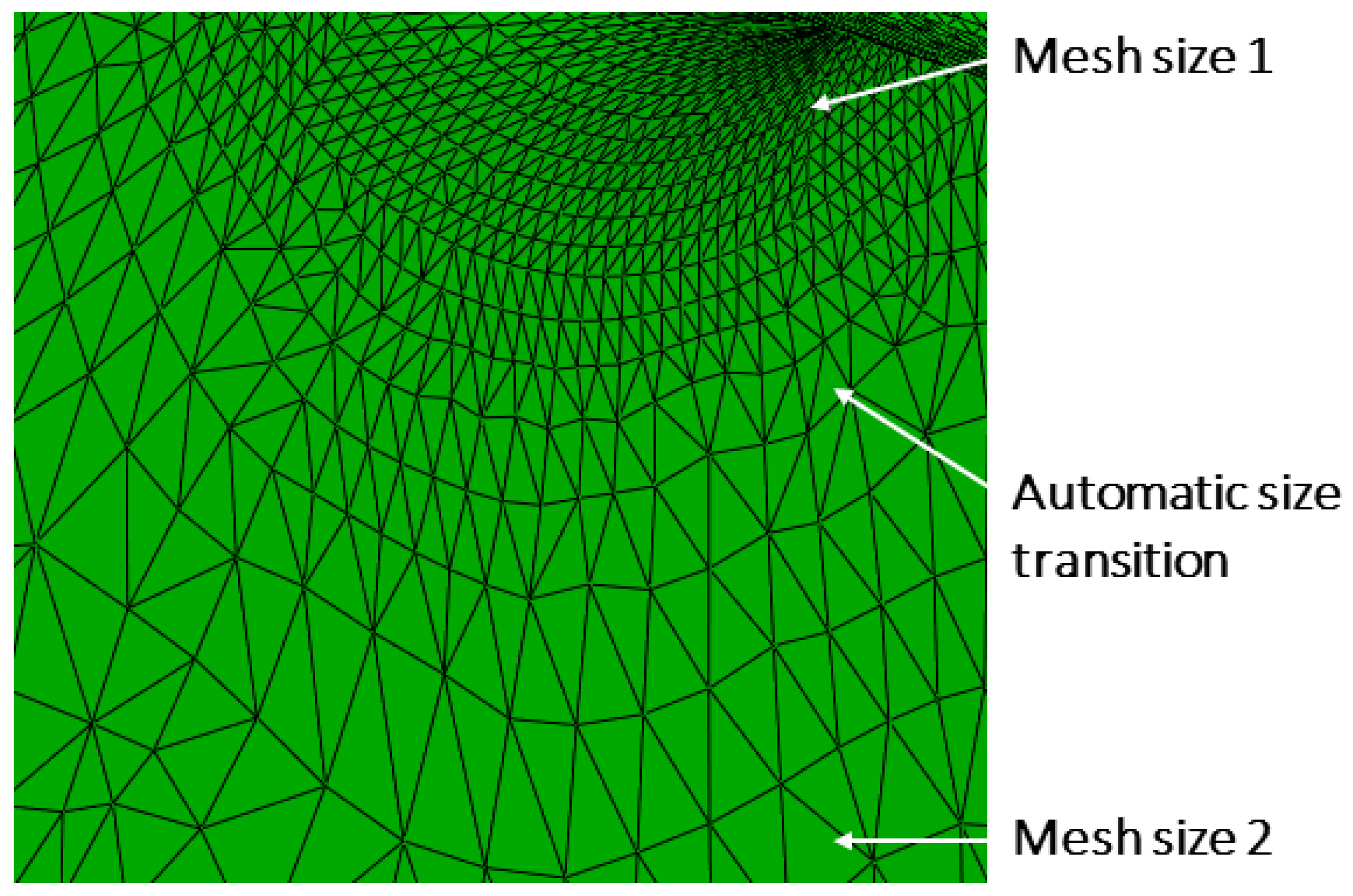
The mesh automation begins with importing the parasolid CAD model. Using a text file, the mesh specification and boundary conditions are imported to the meshing software from the database. The surfaces where boundary conditions would be assigned are stored in an array. Based on the user-defined mesh size, an unstructured volume tetra-mesh is generated. Curvature and proximity features were enabled to capture the shape of the turbine blade. Two different mesh sizes were assigned: a smaller element size was selected for the pins and hole, whereas a larger element size was used for the rest of the blade. This method proves the possibility of assigning different mesh sizes to different surfaces or volumes in a model. Once the mesh is generated, the material and physical properties of the materials are assigned to the model using the TCL script. Afterwards, the total number of surfaces is calculated using the same script, and their corresponding surface area is computed. This computed surface area is compared with the area calculated from the automated CAD model. Once the mesh surface area is matched with any particular surface area from the CAD model, a corresponding boundary condition is assigned to that surface. This method allows for the automatic assignment of pressure and static load to the outer geometry (base model).
Once the initialization parameters for simulation, such as time step, termination time, etc., are set up automatically, the meshed result or model is exported as an FEA software standard 3D model. Similar to meshing and the CAD tool, FEA is also executed through a batch script from its native terminal. The meshed model is then imported into the solver. Since all the boundary conditions are already assigned to the model, the structural simulation is initialized. After the completion of the simulation, a Python script is used to analyze the results in the solver, which scans through all of the elements of the mesh and records the maximum von Mises stress and deflection values. These data, along with other physical properties of the model, are stored in the back-end database.
4. Implementation
The method described above has been applied in the development process of a turbine blade or vane, as shown in
Figure 3. The results can be separated into DA, automation of meshing, and structural simulation.
4.1. Design Automation
One of the important factors to consider while implementing a design automation framework is the level of flexibility in the designs and templates without compromising the efficiency of the intended use. In the base model shown in
Figure 3, the topological parametrization is implemented by using the UDF functionality inside the CAD tool. Initially, high-level CAD templates for different features in the vanes, such as passage walls, impingement holes, and ribs, are manually generated. All of the feature information will be automatically created, which is later accessed by the inference engine to perform DA. Creating parameterized CAD templates allows the morphological change of these models. The user input, which can be fed into the Excel interface, will be used to instantiate morphological and topological UDFs. However, these parameters need to be generic or simple enough that a person with little to no knowledge of this framework can operate it. The user has the provision to control the number of above mentioned geometrical features’ instantiation. The possibility to change the number of cooling passages, ribs, and impingement holes in the leading edge and trailing edge allows for the generation of models with a wide combination of internal cooling structures.
While the population of individual cooling structures can be user-defined, the geometrical parameters of these structures can also be modified. Some of the important parameters that are user-modifiable are shown in
Figure 5. The dimensions of these structures can be changed individually or collectively. The parameterized geometric values of all of the cooling structures are shown in
Table 2. The location, size, and order of repetition can be varied with respect to the dimension of the turbine blade or vane geometry. One of the configurations of the cooling structures produced through this framework is shown in
Figure 6.
4.2. Mesh Automation and Simulation
In order to automate the meshing and automatically identify the boundary condition, an algorithm was developed, as depicted in
Figure 4. During the automatic generation of the CAD, the areas of surfaces where boundary conditions are required were recorded. The values of these surface areas were then appended to the database. The parasolid model exported from the automated CAD module was sent to the inference engine. The inference engine would retrieve mesh specifications (i.e., mesh size or type of mesh) from the database and trigger the TCL script, which automatically initiates the meshing process. The depiction of an automatically generated mesh, utilizing knowledge stored in the database, is presented in
Figure 7. It is essential to set up the structural simulation environment before automating the meshing process; otherwise, the exported mesh would not be in the correct format for performing simulations.
After generating the mesh, material and solid properties can be created and assigned to the mesh using the TCL script. Subsequently, the script can calculate the total number of surfaces and iterate through them to compute their respective surface areas. By utilizing a logical condition, the surface areas of the mesh can be compared to the boundary condition surface area from the CAD. When the CAD boundary surface area matches the surface area in the mesh, the corresponding boundary condition will be automatically assigned using the TCL script. This automated process allows for the definition of pressure surfaces and static load elements.
Next, an output block should be generated to define the simulation output parameters. The initialization parameters for the simulation, such as the time step and termination time, can be automatically assigned during this setup. Subsequently, the meshed model is exported as an FEA software standard 3D model. This model is now ready for structural simulation using the FEA solver.
Using a batch script, the FEA software standard 3D model is injected into the solver terminal. Since all required boundary conditions are already set up in meshing software, the simulation can start uninterrupted. After the simulation is completed, a Python script is used to analyze the results in the solver. The Python script scans through all elements of the mesh, records the maximum von Mises stress and deflection values, and appends them back to the database.
Figure 8 presents a sample of the displacement contour plot obtained from the simple finite element analysis.The contour plot vividly illustrates the displacements, with the boundary conditions automatically applied from the mesh automation module.
5. Discussion
The flexibility of turbine cooling element design has been enhanced through the implementation of DA using high-level CAD templates (HLCT) and reusing information from the knowledge base. By utilizing HLCTs and UDFs to generate repetitive design structures, it becomes possible to achieve a high-level topological parametrization of cooling passage walls, impingement holes, rib turbulators, and other elements. Moreover, the development of parameterized CAD templates with rules and relations for automation increases the level of morphological transformation. By implementing this approach, a simple and generic user interface is provided, empowering users to effortlessly generate cooling structures with a multitude of combinations. This enhancement significantly improves the flexibility of turbine cooling element design, ultimately resulting in increased efficiency and effectiveness within the DA process. However, in the process of making the algorithm and interface generic, certain terminologies have been used, which are expected to remain consistent with the turbine-blade base models. Implementing this method on a different turbine vane requires some preparation involving the appropriate naming of elements in the CAD models. Furthermore, including a back-end database within the automation framework serves as a knowledge base, benefiting not only the DA process but also subsequent stages in the cycle.
The utilization of meshing software for high-level operations, such as automatic mesh generation without the need for geometry cleanup, significantly accelerates the product development process. Despite each stage in this framework having its own individual database, these databases are interconnected, facilitating the seamless transfer of information between different stages. At the end of the automation process, the bodies requiring similar mesh properties are merged into a single body with a generic and recognizable name for the mesh automation algorithm. As this naming process is automated within the DA framework, no pre-preparation is necessary in terms of assigning appropriate terminologies. Assigning different mesh sizes to various surfaces or volumes within the model represents a valuable feature of this methodology. This capability enables a more precise representation of the complex geometry of the turbine blade by utilizing smaller element sizes for pins and holes while employing larger element sizes for the remaining components. The automatic assignment of pressure and static loads to the outer geometry simplifies the process of defining boundary conditions, thereby enhancing the accuracy and reliability of the simulations. However, it is important to acknowledge that while the automated meshing process brings about efficiency gains, it may relinquish some control over the mesh quality in comparison to manual meshing. Therefore, the trade-off between automation and mesh quality should be carefully considered based on the specific requirements and accuracy needs of the analysis.
The presented framework automates design generation, mesh generation, and boundary condition assignment for structural simulations. However, it lacks the capabilities for aerodynamic evaluations, thermo–mechanical fatigue simulations, and life cycle evaluations necessary for comprehensive turbine vane cooling channel development. The framework’s modular design allows easy integration of additional software modules, and its standardized approach and centralized database ensure robustness and flexibility. Once these additions are made, the framework can serve as a black box solution for the optimization process, thereby enhancing performance, reliability, and efficiency in turbine vane cooling channel design.
6. Conclusions
This paper presents a novel framework that offers an automated and multidisciplinary approach to designing and analyzing cooling channels in high-pressure turbine blades. Through the integration of DA, meshing automation, and structural analysis, the framework demonstrates advantages in streamlining and expediting various aspects of gas turbine development. This approach proves beneficial for iterative and time-consuming tasks, alleviating labor-intensive processes and offering a promising avenue for enhancing the overall workflow efficiency.
Author Contributions
Conceptualization, S.N. and M.T.; methodology, S.N., A.A.A., and H.T.; software, S.N., A.A.A., and H.T.; validation, S.N., A.W., and M.T.; resources, M.T.; writing—original draft preparation, S.N.; writing—review and editing, S.N.; visualization, S.N. and A.A.A.; supervision, M.T. and A.W.; project administration, M.T.; funding acquisition, M.T. All authors have read and agreed to the published version of the manuscript.
Funding
This research was funded by Vinnova, d’Light: Design easily and quickly—green gas turbines based on innovative lightweight solutions in the venture ’The strategic Innovation programme SIP LIGHTer’ (2020-04251).
Institutional Review Board Statement
Not applicable.
Informed Consent Statement
Not applicable.
Data Availability Statement
Data are contained within the article.
Conflicts of Interest
The authors declare no conflict of interest.
Abbreviations
The following abbreviations are used in this manuscript:
| CAD | Computer-Aided Design |
| DA | Design Automation |
| KBE | Knowledge-Based Engineering |
| MDO | Multi-Disciplinary Optimization |
| HLCT | High-Level CAD Template |
References
- National Academies of Sciences. Advanced Technologies for Gas Turbines; National Academies Press: Washington, DC, USA, 2020. [Google Scholar]
- Zhang, G.; Rui, Z.; Gongnan, X.; Shulei, L.; Sunde, B. Optimization of cooling structures in gas turbines: A review. Chin. J. Aeronaut. 2022, 35, 18–46. [Google Scholar] [CrossRef]
- Chapman, C.B.; Pinfold, M. The application of a knowledge based engineering approach to the rapid design and analysis of an automotive structure. Adv. Eng. Softw. 2001, 32, 903–912. [Google Scholar] [CrossRef]
- Cederfeldt, M.; Elgh, F. Design automation in SMEs-current state, potential, need and requirements. In Proceedings of the DS 35: Proceedings ICED 05, the 15th International Conference on Engineering Design, Melbourne, Australia, 15–18 August 2005; pp. 248–249. [Google Scholar]
- Siddique, Z.; Zhou, Y. Automatic generation of product family member CAD models supported by a platform using a template approach. In Proceedings of the International Design Engineering Technical Conferences and Computers and Information in Engineering Conference, San Jose, CA, USA, 10–14 November 2002; Volume 36215, pp. 197–203. [Google Scholar] [CrossRef]
- Elgh, F. Decision support in the quotation process of engineered-to-order products. Adv. Eng. Inform. 2012, 26, 66–79. [Google Scholar] [CrossRef]
- Ulrich, K.; Eppinger, S. Product Design and Development; McGraw Hill: New York City, NY, USA, 2011. [Google Scholar]
- Nambiar, S.; Albert, A.; Rimmalapudi, V.; Acharya, V.; Tarkian, M.; Kihlman, M. Autofix–Automated Design of Fixtures. Proc. Des. Soc. 2022, 2, 543–552. [Google Scholar] [CrossRef]
- Cederfeldt, M. Planning Design Automation: A Structured Method and Supporting Tools. Ph.D. Thesis, Department of Product and Production Development, Chalmers University of Technology, Göteborg, Sweden, 2007. [Google Scholar]
- Vidner, O.; Wehlin, C.; Wiberg, A. Design Automation Systems for the Product Development Process: Reflections from Five Industrial Case Studies. Proc. Des. Soc. 2022, 2, 2533–2542. [Google Scholar] [CrossRef]
- Poorkiany, M. Support Maintenance of Design Automation Systems-A Framework to Capture, Structure and Access Design Rationale. Ph.D. Thesis, School of Engineering, Jönköping University, Jönköping, Sweden, 2015. [Google Scholar]
- Stjepandić, J.; Verhagen, W.J.; Liese, H.; Bermell-Garcia, P. Knowledge-based engineering. In Concurrent Engineering in the 21st Century: Foundations, Developments and Challenges; Springer: Cham, Switzerland, 2015; pp. 255–286. [Google Scholar]
- Tarkian, M. Design Automation for Multidisciplinary Optimization: A High Level CAD Template Approach. Ph.D. Thesis, Linköping University Electronic Press, Linköping, Sweden, 2012. [Google Scholar]
- Amadori, K.; Tarkian, M.; Ölvander, J.; Krus, P. Flexible and robust CAD models for design automation. Adv. Eng. Inform. 2012, 26, 180–195. [Google Scholar] [CrossRef]
- Chi, Z.; Wang, S.; Ren, J.; Jiang, H. Multi-dimensional platform for cooling design of air-cooled turbine blades. In Proceedings of the Turbo Expo: Power for Land, Sea, and Air. American Society of Mechanical Engineers, Copenhagen, Denmark, 11–15 June 2012; Volume 44700, pp. 207–218. [Google Scholar] [CrossRef]
- Lu, S.; Chi, Z.; Wang, S.; Wen, F.; Feng, G. Full three-dimensional optimization platform of turbine blades considering the film cooling. In Proceedings of the Turbo Expo: Power for Land, Sea, and Air. American Society of Mechanical Engineers, San Antonio, TX, USA, 3–7 June 2013; Volume 55232, p. V06BT43A002. [Google Scholar] [CrossRef]
- Chi, Z.; Ren, J.; Jiang, H. Cooling Structure Optimization for a Rib-Roughed Channel in a Turbine Rotor Blade. In Proceedings of the Turbo Expo: Power for Land, Sea, and Air. American Society of Mechanical Engineers, San Antonio, TX, USA, 3–7 June 2013; Volume 55157, p. V03BT11A009. [Google Scholar] [CrossRef]
- Yeranee, K.; Rao, Y.; Yang, L.; Li, H. Enhanced thermal performance of a pin-fin cooling channel for gas turbine blade by density-based topology optimization. Int. J. Therm. Sci. 2022, 181, 107783. [Google Scholar] [CrossRef]
- Xu, L.; Ruan, Q.; Shen, Q.; Xi, L.; Gao, J.; Li, Y. Optimization Design of Lattice Structures in Internal Cooling Channel with Variable Aspect Ratio of Gas Turbine Blade. Energies 2021, 14, 3954. [Google Scholar] [CrossRef]
- Ghosh, S.; Mondal, S.; Kapat, J.S.; Ray, A. Shape Optimization of Pin Fin Arrays Using Gaussian Process Surrogate Models Under Design Constraints. In Proceedings of the Turbo Expo: Power for Land, Sea, and Air. American Society of Mechanical Engineers, Virtual, 21–25 September 2020; Volume 84164, p. V07AT15A021. [Google Scholar] [CrossRef]
- Xiaodong, Q.; Xiuli, S. Multidisciplinary design optimization of turbine disks based on ANSYS Workbench platforms. Procedia Eng. 2015, 99, 1275–1283. [Google Scholar] [CrossRef]
- Zhang, M.; Gou, W.; Li, L.; Wang, X.; Yue, Z. Multidisciplinary design and optimization of the twin-web turbine disk. Struct. Multidiscip. Optim. 2016, 53, 1129–1141. [Google Scholar] [CrossRef]
- Li, L.; Wan, H.; Gao, W.; Tong, F.; Li, H. Reliability based multidisciplinary design optimization of cooling turbine blade considering uncertainty data statistics. Struct. Multidiscip. Optim. 2019, 59, 659–673. [Google Scholar] [CrossRef]
- Tarkian, M. Design Reuse and Automation: On High Level Cad Modeling for Multidisciplinary Design and Optimization. Ph.D. Thesis, Linköping University Electronic Press: Linköping, Sweden, 2009. [Google Scholar]
- Nagaiah, N.R.; Geiger, C.D. Design Optimization of Gas Turbine Blade Internal Cooling Channels. IIE Annu. Conf. Proc. 2013, 2013, 2273–2282. [Google Scholar]
- Song, W.; Keane, A.; Rees, J.; Bhaskar, A.; Bagnall, S. Turbine blade fir-tree root design optimisation using intelligent CAD and finite element analysis. Comput. Struct. 2002, 80, 1853–1867. [Google Scholar] [CrossRef]
- Willeke, S.; Verstraete, T. Adjoint optimization of an internal cooling channel u-bend. In Proceedings of the Turbo Expo: Power for Land, Sea, and Air. American Society of Mechanical Engineers, Montreal, QC, Canada, 15–19 June 2015; Volume 56710, p. V05AT11A029. [Google Scholar] [CrossRef]
- Chi, Z.; Ren, J.; Jiang, H. Coupled aerothermodynamics optimization for the cooling system of a turbine vane. J. Turbomach. 2014, 136, 051008. [Google Scholar] [CrossRef]
- Dennis, B.H.; Egorov, I.N.; Sobieczky, H.; Dulikravich, G.S.; Yoshimura, S. Parallel thermoelasticity optimization of 3-D serpentine cooling passages in turbine blades. In Proceedings of the Turbo Expo: Power for Land, Sea, and Air, Atlanta, GA, USA, 16–19 June 2003; Volume 36894, pp. 1215–1223. [Google Scholar] [CrossRef]
- Olofsson, J.; Salomonsson, K.; Johansson, J.; Amouzgar, K. A methodology for microstructure-based structural optimization of cast and injection moulded parts using knowledge-based design automation. Adv. Eng. Softw. 2017, 109, 44–52. [Google Scholar] [CrossRef]
- Bhavikatti, S. Finite Element Analysis; New Age International: Delhi, IN, USA, 2005. [Google Scholar]
- Chang, L. Simulation Analysis of Finite Element Preprocessing based on HyperMesh. In Proceedings of the 2020 International Wireless Communications and Mobile Computing (IWCMC), Limassol, Cyprus, 15–19 June 2020; pp. 1202–1207. [Google Scholar] [CrossRef]
- Siemens Digital Industries Software. NX CAD and CAM Software. Version 1980. June 2021. Available online: https://plm.sw.siemens.com/en-US/nx/ (accessed on 11 January 2024).
- Altair Engineering, Inc. Altair HyperMesh. 2022. Available online: https://altair.com/hypermesh (accessed on 11 January 2024).
- Dassault Systemes. Abaqus. Version 6.12-3. June 2022. Available online: https://www.3ds.com/products/simulia/abaqus (accessed on 11 January 2024).
| Disclaimer/Publisher’s Note: The statements, opinions and data contained in all publications are solely those of the individual author(s) and contributor(s) and not of MDPI and/or the editor(s). MDPI and/or the editor(s) disclaim responsibility for any injury to people or property resulting from any ideas, methods, instructions or products referred to in the content. |
© 2024 by the authors. Licensee MDPI, Basel, Switzerland. This article is an open access article distributed under the terms and conditions of the Creative Commons Attribution (CC BY-NC-ND) license (https://creativecommons.org/licenses/by-nc-nd/4.0/).


