1. Introduction
Volumetric interfaces and displays have been an area of substantial focus in HCI, bringing about new ways to enhance interactivity, learning, and understanding as an extension to existing modalities. While much research in the area exists, current haptic display projects tend to be difficult to implement as part of existing visual display technologies. Moreover, visual imagery is often an afterthought when designing haptic displays. When implemented, it often relies on techniques not suited for portability, such as overhead projection. This limits the places and situations in which the current state of volumetric haptic displays can be used. Existing commercially volumetric haptic technologies available on the market tend to separate the visual (stereoscopic) component from the volumetric haptic component (afferent flow), which often consists of a nearby display or is in conjunction with a VR/AR headset display. While this may work well in a controlled environment with fixed equipment to provide an enhanced experience, these products are not designed to be used or integrated into the more common devices and displays we use daily.
We propose using a simple quad-stepper motor configuration to provide a low-cost universal haptic actuation platform that can be easily integrated with, attached, or placed below a tablet or phone. What this means in practice is that the platform is independent, hence universal, from the device in use. The critical aspect proposed here is the stepper motor configuration which allows 6DOF movements through the X, Y, and Z planes. In addition, pressure is easily modified under the fingertip without changing finger displacement in the orthogonal direction to the screen [
1]. We build a proof of concept, on which a tablet or similar display can be placed onto to introduce volumetric haptics to the device. We demonstrate the relative ease and repeatability of design and construction. Additionally, an initial small-scale user test is run to confirm the preliminary effectiveness of the current prototype in its ability to simulate the physical features of keyboard keycaps found on a standard laptop keyboard over the flat display of a Surface Go tablet. With a standard keyboard, users can locate the position of keys as they type with their fingers sliding naturally across the keycaps to explore their physical features. This ability to find and explore keycap positions consists of the current 3D features we seek to demonstrate with the initial prototype described in this paper.
The structure of this paper begins with the introduction that describes the research we are working on, the problem we are addressing, and our aims and objectives. We then formulate our research questions into a hypothesis. Related works are collected and reviewed in the third section, offering a solid background and the latest state-of-the-art research to reference. Before moving forward with our research, we need to create a model to be used for volumetric rendering. For this reason, in section four, we review the data collected to develop the initial prototype. With this rendering model ready, we provide a detailed description of the hardware built for this study. It is followed by a thorough review of the software created in conjunction with the hardware for use in the study. In the seventh section, we outline the user study design, followed by the results in section eight. A discussion of the prior results and possible broader applications is presented. In the concluding section, we present our conclusion, recommendations, and future proposals for the continuation of related research.
2. Hypotheses
As it has been suggested and proven by Lederman et al. [
2,
3,
4,
5,
6,
7] by demonstrating that physical 3D common objects can be recognized instantly and very efficiently through haptic exploration, exploratory procedures can be used to augment finger-based interaction with mobile touchscreens.
Measurements of metrics extracted from interactive data during haptic exploration of plastic keycaps (physical objects) will allow modifying fingertip light touch force feedback by altering the afferent haptic flow. With the help of a regular flat touch screen over a floating surface, the illusion of non-planar keycaps can be induced via the replication of raising and deepening of the attributes of the virtual objects at specific target areas along the scanpaths of the fingertip.
Through the current work and build of the prototype, we hypothesize that it can be used to successfully emulate the features of feelable mechanical keycaps (the convex shape, borders, and valleys) over the flat surface of a tablet, thus allowing for the exploratory feel that can only be provided by a physical keyboard. This should be demonstrated through parameters of accurate fingertip navigation over a virtual keyboard, as well as substantiated by participants’ subjective responses.
3. Background and Related Works
As mentioned in the introduction section, many other attempts have been demonstrated regarding designing volumetric shape displays. Here, we discuss the current state-of-the-art volumetric haptic displays.
A good example of this is the inFORCE shape display prototype proof of concept implemented by Ken Nakagaki and his team at the MIT Media Lab [
8]. It is a shape display that uses the bed of pins design, a mechanical arrangement proven to work via many other implementations [
9,
10,
11,
12,
13]. Nagaki’s prototype is complemented with projected visuals onto the bed of pins, which are raised upwards proportionally to the top surface of the simulated 3D object that can be explored by hand. While the implementation of the bed of pins display is quite effective when simulating volume, it is held back by its often cumbersome design requirements related to the physical size of the pins themselves alongside accompanying actuator technology [
14] as well as the current inability to integrate with modern display technologies.
Ultrasound has also been well studied as a method of rendering volumetric shapes in mid-air. In one of the most notable examples, Benjamin Long and his team at the University of Bristol have successfully presented a method for creating haptic shapes in mid-air [
15]. This method has been further developed into the UltraHaptics system used by other researchers in the field to further explore its possible use and implementation in use cases where volumetric haptics could be helpful [
16,
17,
18,
19,
20,
21]. The advantage is that this allows the rendering of feelable shapes within a wide space in mid-air. Once again, we see a limitation to the display technologies that can be incorporated. Due to the arrangement and placement of the ultrasonic actuators, there is no reflection surface or visual plane on which an image can be projected, nor can a display be placed over the actuators as it would impede the ultrasonic output. While the implementation of mid-air haptics through the use of a combined ultrasonic array can create explorable and feelable objects, the low intensity of the haptic points does not provide the adjustable physical response one could expect from a repulsion force of a virtual surface (>0.5 N), thus not allowing the feeling of volumetric feedback [
22,
23]. Seki Inoue and his team implement a similar combination array of ultrasonic actuators within an orthogonal cavity to create feelable haptic objects [
24] with similarly documented effects and conclusions.
The 3D Tractus and TouchMover [
25,
26,
27] are earlier examples of devices for interaction and exploration of 3D data that use a wide single-axis range of movement to successfully emulate the feeling of volume on a laptop and a large touchscreen display. The cited works show that by actuating a single axis of depth combined with stereoscopic 3D visual cues, the volume of virtual shapes can be successfully conveyed to users of said devices without the need for additional use of handheld peripherals. The limitation of a single axis brings into question the degree to which similar devices could be immersive if they could actuate similarly with six degrees of freedom.
As we explore volumetric haptic surfaces on a flat display, it is with deep interest that we look at the work of Dongbum Pyo’s team on dielectric elastomers [
28]. Dielectrics enable an array of actuators within a transparent thin film that can be placed in the top layer of a display stack. While a loss of brightness does exist, it has been shown to convey depth and texture successfully. The thin 500 µm implementation means that this type of display suits modern display technologies. The limitations come from the limited displacement at an amplitude of around 12 µm. While this is suitable to suggest changes in shape or volume, the volume characteristics are somewhat limited [
22].
Other techniques that aim to emulate volumetric feedback come in the form of wearable haptic displays. For example, the work of Adel et al. introduces a finger splint with an attached magnet where a volumetric feelable and explorable space is designed above an array of powerful electromagnets [
29], similar to the array of pins methods. Still, through wearable technology, a force can be precisely adjusted when applied to the fingertip using a controllable magnetic field. As there is no need for direct physical feedback via the grasp of the fingertip, such an implementation opens up new possibilities such that it is possible to provide volumetric haptic feedback in regular displays when the magnetic field could be placed behind it.
Yet, as we look at the shift from a base device to wearable gloves, we see several emerging technologies from the private sector that use similar finger restrainment systems [
30,
31,
32,
33,
34,
35] where a glove provides a resistive force that does not allow movement of the user’s fingers. It can be useful when the need is to simulate holding an object. These techniques are often limited in simulating the ability to push an object or to simulate activities such as typing, an activity that does not require a user to hold the keys, but rather press them down. It is also, for the moment, demonstrably limited to VR and AR environments. There are attempts to incorporate haptic feedback via holographic displays [
36], but these displays require additional equipment that may not integrate with today’s devices. An interesting hand-worn device by Trinitova et al. [
37] allows application of pressure to the palm, improving the sensation of weight as expected when interacting with an object. These principles of repulsive and attractive forces found in the mentioned products and research are essential to consider while attempting to simulate mechanical feedback.
The use of air as an interaction medium continues to be of interest due to the possibility of implementation without requiring the user to wear cumbersome equipment such as haptic gloves or fingertip caps [
38,
39]. For this reason, we continue to see implementations that use this medium better. Christou et al. implement a spatial haptics system dubbed aerohaptics that uses an air blower on a servo configuration that allows it blowing along an XYZ offset [
40]. It shows the continued interest in the field to create spatial volumetric haptics that can be felt without the need to wear additional hardware on their person.
In general, we see many novel ways to produce volumetric feedback, including using unmanned drones to simulate objects in virtual space or repurposing robotic arms for similar purposes [
41]. It should be noted that kinesthetic devices (e.g., Novint’s Falcon Haptic Device) available on the market can accurately generate vector torque transferred to the user’s fingertips through a manipulandum or an attached display [
42,
43]. While many systems have been proposed and continue to exist, there is yet to be a low-cost implementation that can complement standard consumer devices such as phones, tablets, and other touch-sensitive surfaces equipped with onscreen keyboards or naked-eye stereoscopic display technologies.
Similar to our prototype, other earlier studies have successfully expressed the deformation of the fingertip’s skin as caused by the tangential force on the fingertip by using a spring–mass–damper model [
44,
45,
46], thereby indicating a linear relationship between the deformation and force. This assumption holds provided that the skin deformation is insignificant and the normal load on the finger is constant, which has typically been observed and recorded during exploratory procedures (EPs) [
23]. Based on this model, the fingertip’s deformation can be estimated from the tangential force and vice versa.
The work with a prototype that most closely resembles ours is that with SurfTics by Hausberger et al. [
47]. Here, we see a potentially universal platform that provides 3DOF to a given surface, such as a tablet device. In this case, the limiting of degrees of freedom was proposed as a cut-cutting measure to keep their device simple while providing a wide range of feedback. Other systems have been limited to 3DOF for similar reasons [
43]. Attempts to expand on this form of feedback have been made in novel manners, for example, as an array of tilt displays to compose a larger display, allowing for an increased resolution of individual tilt zones [
48]. Unfortunately, this solution introduces additional complexity as it fails to produce feedback along the vertical and horizontal planes. In our prototype, we tried to show that expanding such design with a different approach to actuate the universal plate can lead to a relatively simple and low-cost design that expands the range of motion to include vertical and horizontal motions, thus allowing for more in-depth feedback that can be created as a more true-to-life experience without introducing undue complexity or cost.
4. Data Collection for Rendering
As the goals rely on the need for a base prototype development to measure and document the forces involved, we started by discussing this initial working prototype designed to analyze the fingertip load during the exploratory procedures of the mechanical laptop keyboard keycaps. Here, we discuss our decision to develop custom equipment, our process of collecting initial keycap exploration behaviors, and we present a brief discussion of the results. We then introduce the software interface we developed to render the virtualized volumetric keycaps. We created this demonstrator with the ability to measure 0.1–5 N input forces with our selected force sensor technology, as described in the following section. Because the hand’s finger should not contain any linkages, markers, or tags, our research can only rely on measurable parameters of free finger activity such as the light touch scanning the surface. This primarily consists of load or applied force (F(t)) executed by the fingertip dynamically pressed against the button edges, convex keycap profiles and valleys, or the surface at the specific location along the exploratory region. For this reason, we chose to construct a custom physical model to capture pressure along scanpaths over keycaps during light-touch exploratory behavior. In our implementation, the exploratory region contains three keycaps.
4.1. Custom Equipment
We constructed a physical model of an exploration region that allows the deviation of each plastic keycap surface in a normal direction of ±2 mm at a load within a range of 0–100 gF (about 0–1 N) [
22]. The demo has three physical keycaps as well as an integrated force sensor to collect user force input data in various scenarios of shape recognition during light touch exploration (LTE). The selected FSR 400 series is specified to accurately measure forces from 0.2 to 20 N along a specified force vector angle. The lower limit can be preloaded with an adjustable built-in spring to calibrate it to measure from a starting point of 0 N. Precision should be achieved at most 0.25 N of the normal force feedback.
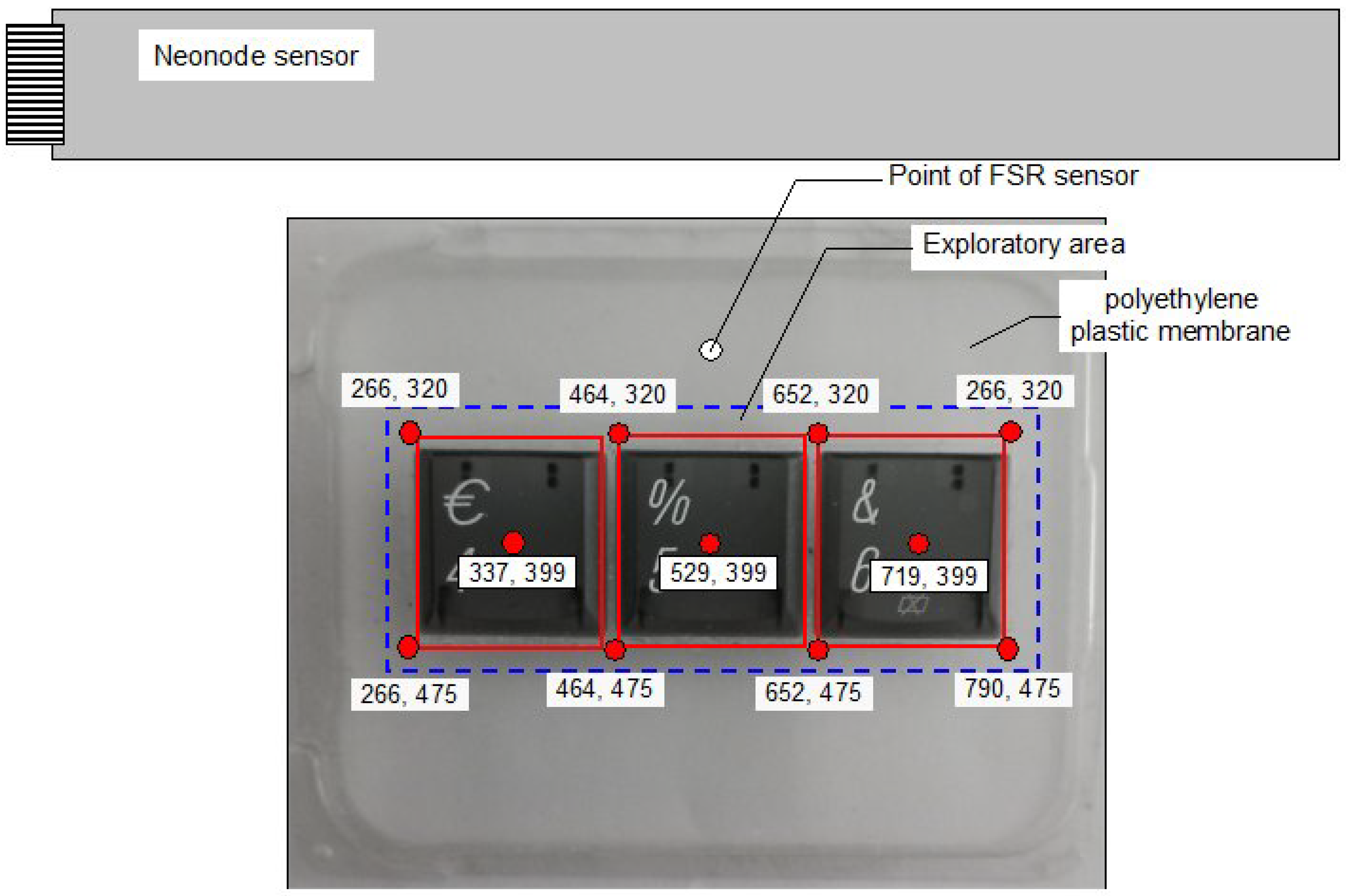
As shown in
Figure 1, three polycarbonate low-profile keycaps of 18 mm × 17 mm with a distance of 1 mm between buttons with edges at a 45-degree tilt at the perimeter were affixed with a double-side tape to a polyethylene plastic membrane of 300
m thickness and a size of 58 mm × 74 mm raised over a 6 mm thick base. The active exploratory area (
Figure 1) was 62 mm × 22 mm. Thus, exploratory procedures of keycaps by fingertip can comprise either the movements along or crossing the convex borders, central concave surface, and valleys between keycaps. A Neonode sensor collected finger position data along the XY plane.
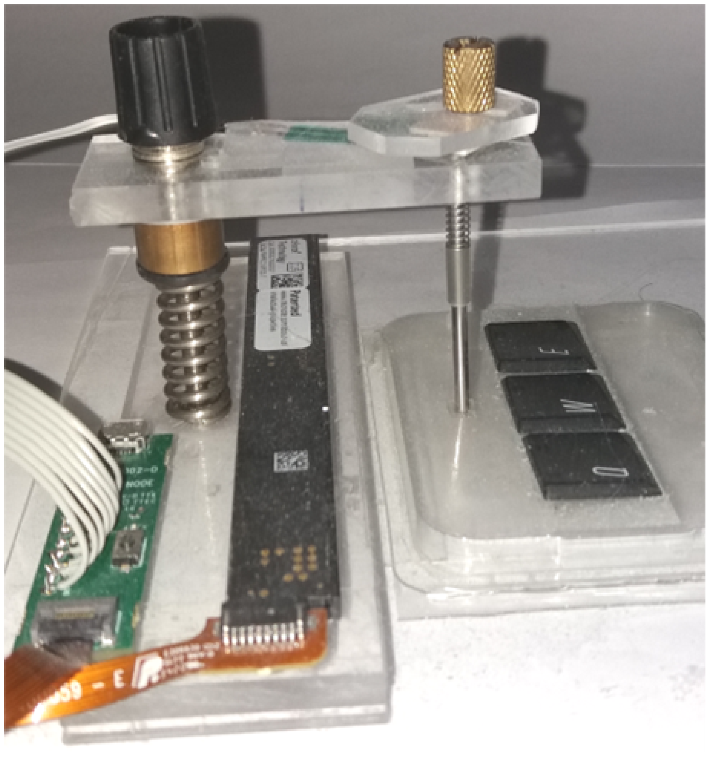
Figure 2 shows the data collection device in its entirety.
4.2. Designing Keycap Exploration Data Collection
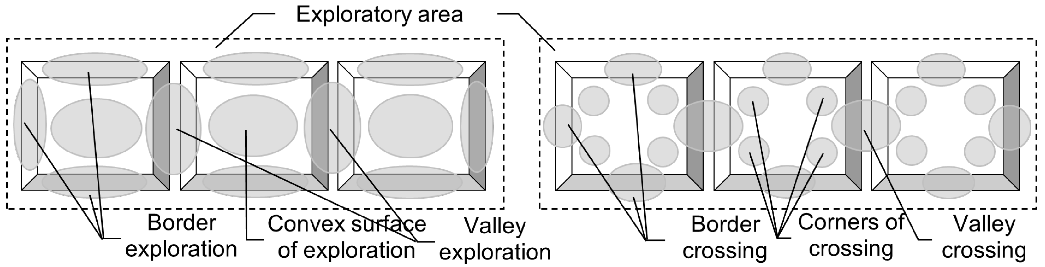
To easily synchronize the superposition of multiple EPs, we invited a group of six participants to explore the three keycaps. We decided to formalize possible exploratory types of behaviors by asking the first group of participants (right-handed, four males and two females) to explore the three plastic keycaps by moving their index fingertip continuously in a horizontal plane with light pressure along the surface and edges of physical keycaps. In the preliminary study, the first group of participants (six persons) continuously used a light-touch exploration of three plastic keycaps from the start to the end position, by feeling, as much as possible, the edges and surfaces of the keycaps. The possible exploration scanpaths were sorted out and adjusted to formalize further research and processing. The printed map of the exploratory area is indicated in
Figure 3; it was presented to the participants. They were allowed as many trials as necessary to familiarize themselves with the interface operation that records the exploratory behavioral data.
4.3. Results of Three Keycaps LTE
The new group of participants included three people, each asked to reproduce two types of exploratory behaviors: one along the borders of each keycap and another by crossing the flat (slightly concave) areas, corners, and valleys of the three keycaps.
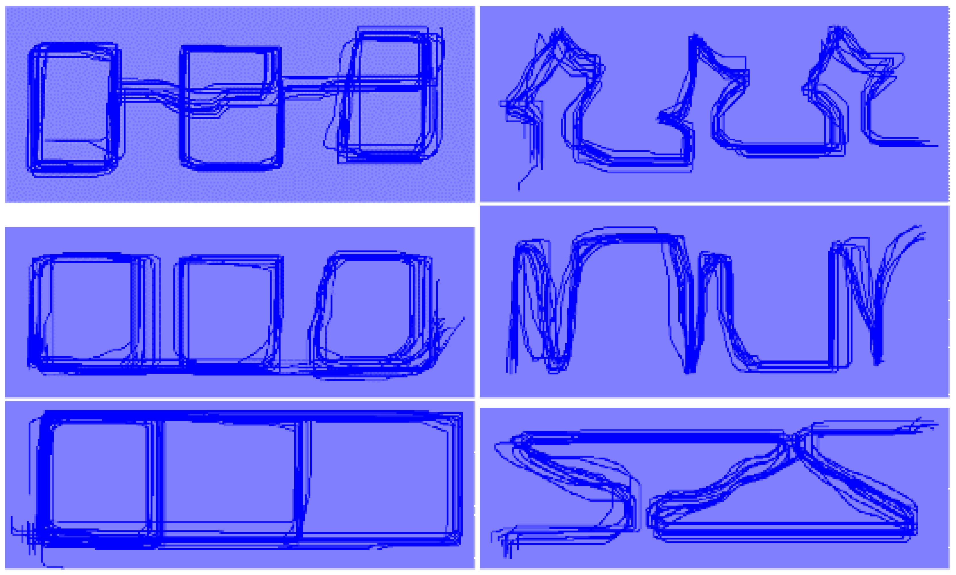
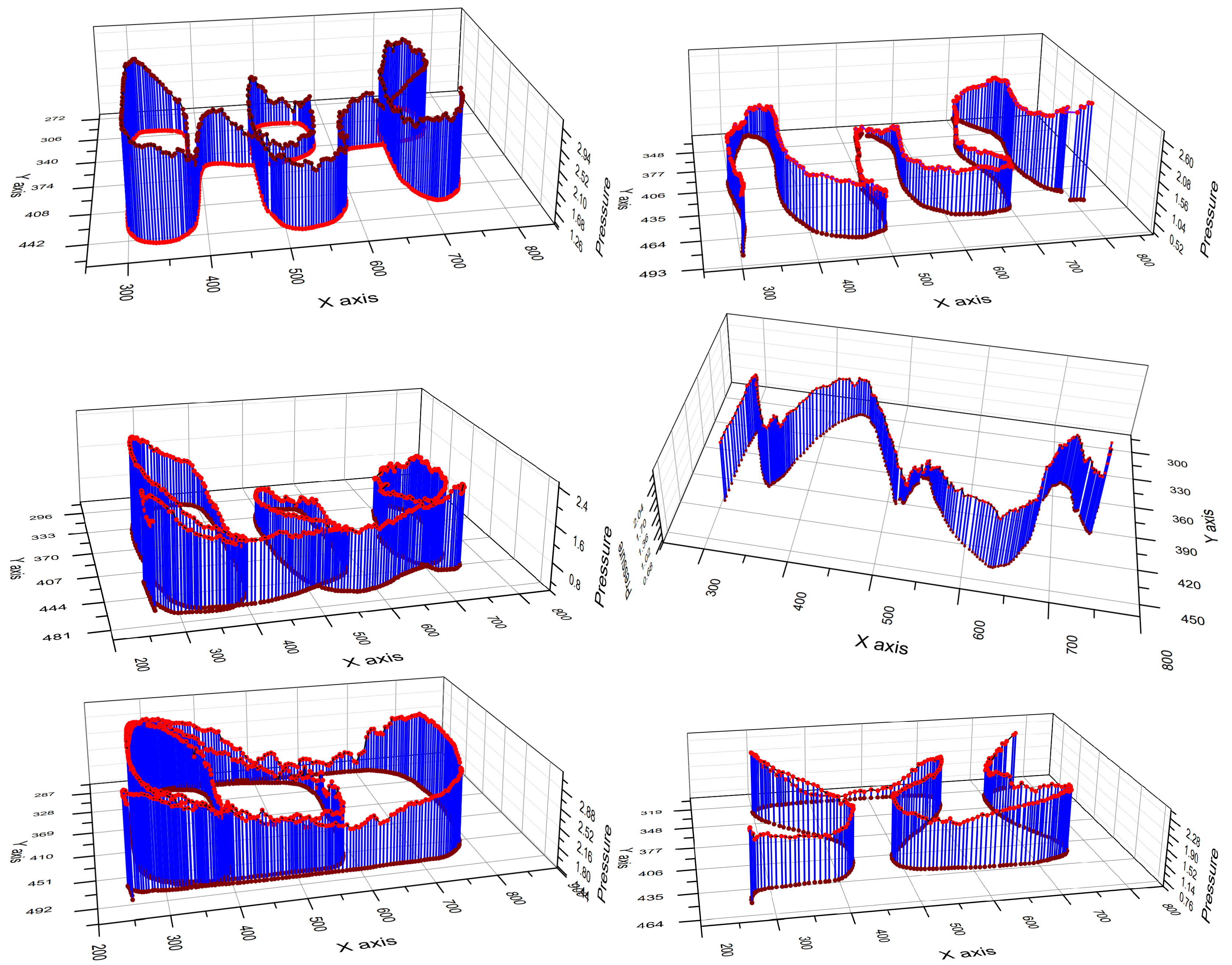
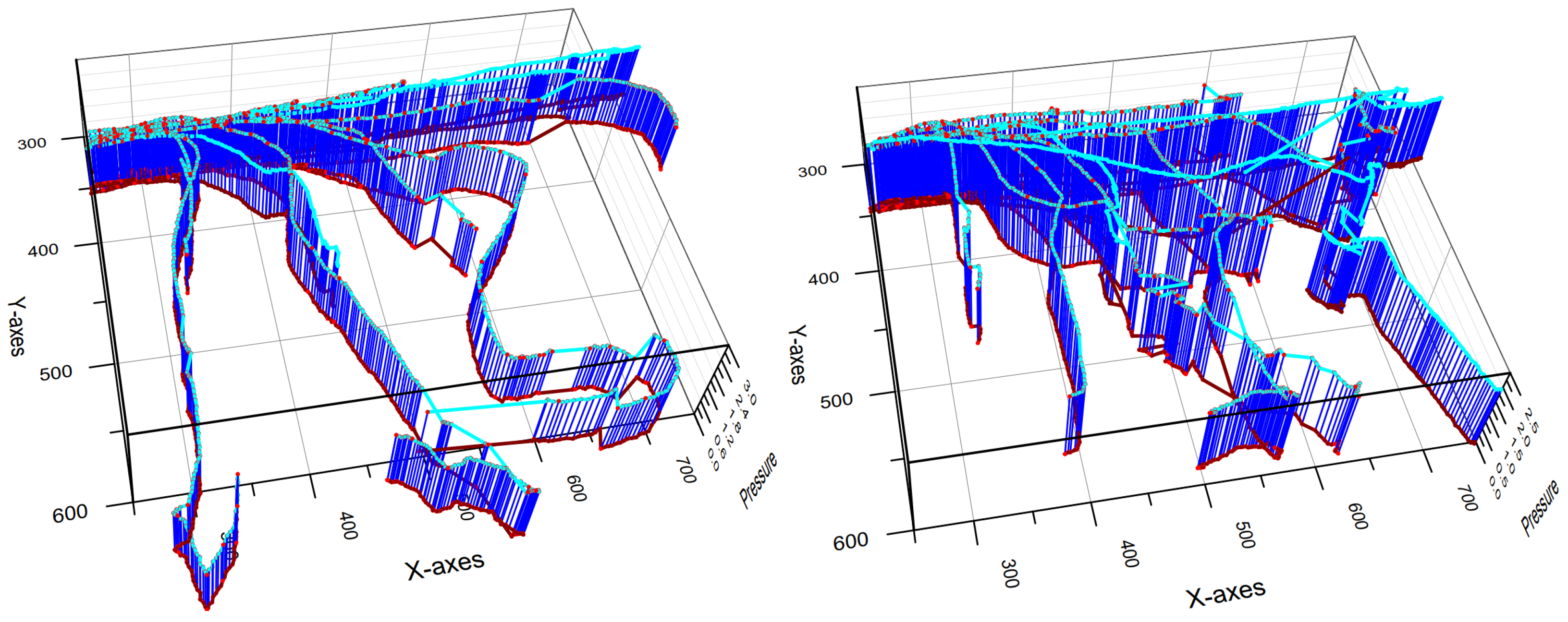
After the fourth probe trial, each type of behavior was reproduced twelve times by each participant, using the index or middle finger of the dominant hand (right in all cases). Thus, each of the six exploratory behaviors was recorded thirty-six times with no restriction for time and visual feedback. The averaged data of exploratory procedures superposition of one novice participant are presented as 2D plots in
Figure 4 and 3D plots, including averaged pressure values, in
Figure 5.
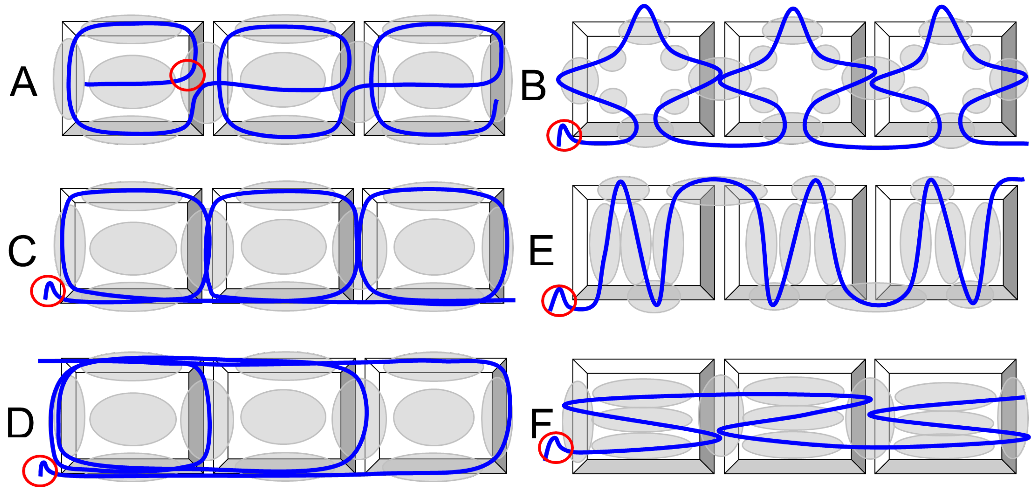
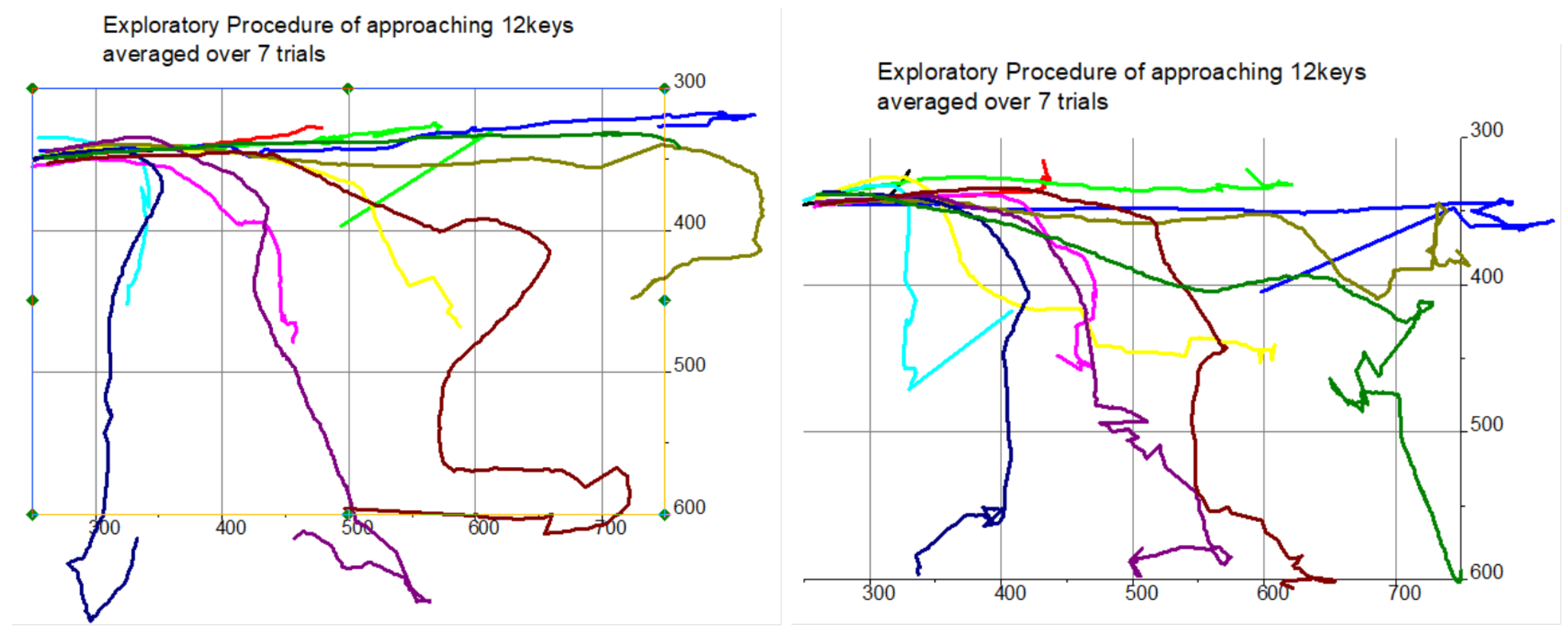
As a result of this data collection, six different exploratory procedures (
Figure 4) were recorded and analyzed to formalize the testing procedure further. The superposition of multiple exploratory procedures was implemented by detecting the small intentionally raised pattern indicated within the red circle in
Figure 6. The data presented in
Figure 5 were segmented into zones (marked by the grey ovals shown in
Figure 1) with the normal pressure force averaged over each zone.
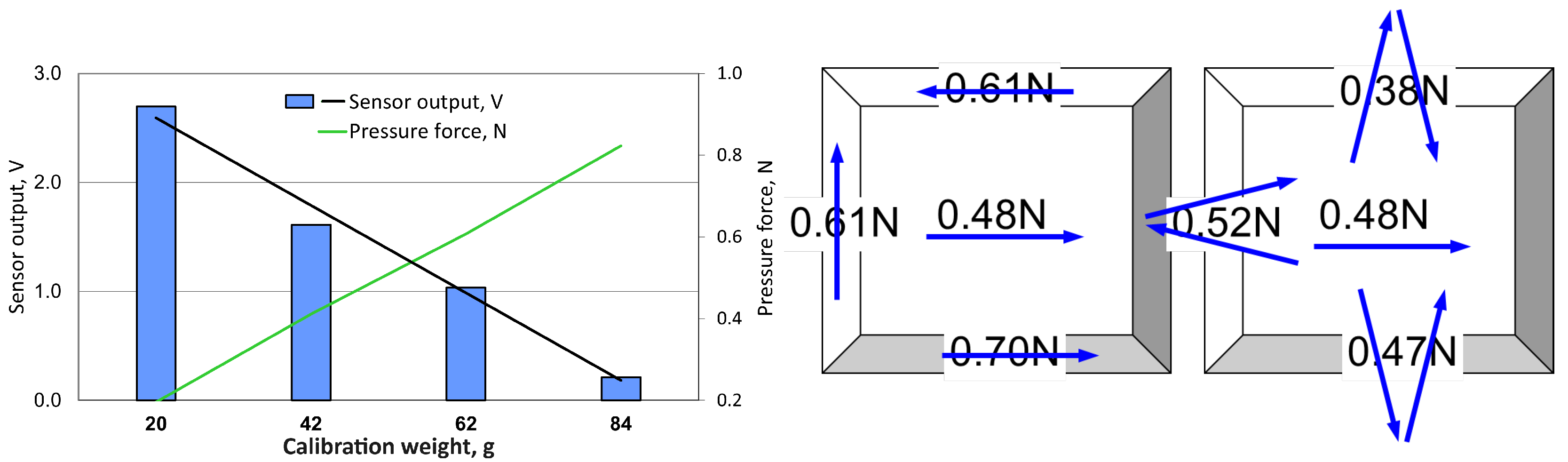
To ensure consistency, the setup was calibrated before each of the 12 trials using calibration weights (20, 42, 62, and 84 g). The calibration curve (nomogram), which displays ratios between sensor output values (in V) and normal force (in N) produced by calibrated weights simulating fingertip pressure, is presented in
Figure 7. The overall data for tracking the three keycaps (left, middle, and right) were integrated and shown in
Table 1. After converting the data according to the calibration curve, the grand average normal force (in Newtons) projected to the location of the fingertips using a light-touch EP over the three keycaps is presented in
Figure 7. Blue vectors indicate fingertip movements related to the EP segments while recording the corresponding normal force.
4.4. SW Interface for Haptic Rendering Three Volumetric Keycaps
From the data collected with the data collection equipment in the previous section, an initial demonstrator can be designed to operate in combination with a measurable force sensor output. The exploratory data from the shape recognition Tasks, along with the force input data collected, can be used as a reference to the necessary repulsion forces of the flat surface that need to be applied to the fingertip to successfully simulate the same shape comprehension tasks when given similar exploration input angles. When applying these repulsion forces, the active force input data can be looped in together to actuate the forces necessary to simulate the creation of virtual keycap shapes.
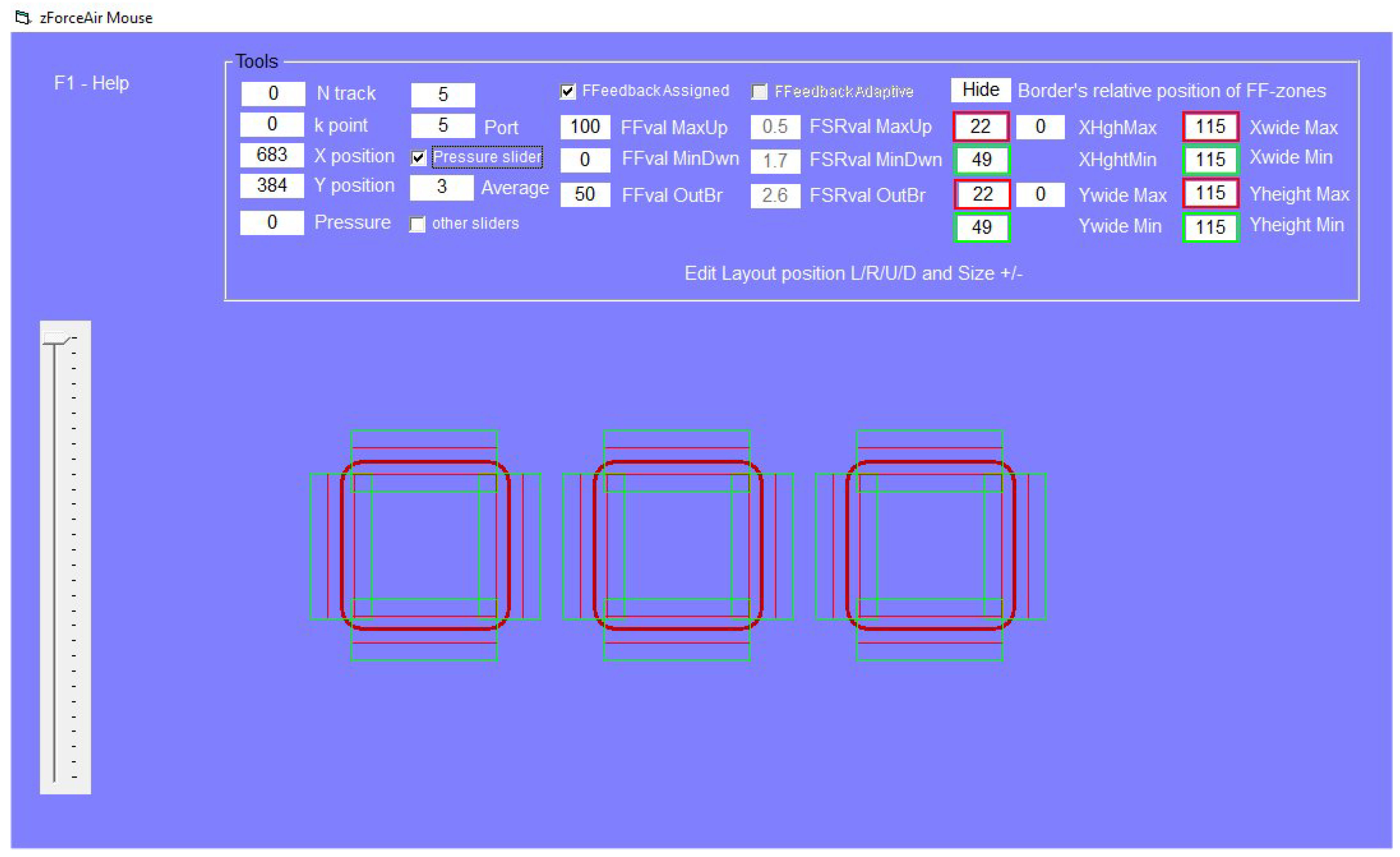
Figure 8 demonstrates the initial software interface in use. The slider on the left represents pressure recorded by the FSR sensor. The large central area on the bottom shows the keycaps region rendering, with feedback changes happening as the finger crosses over the boundary areas. The virtual keycaps and their boundaries are seen from the laptop interface. Each line and color represents a different boundary that triggers the appropriate output stepper position, creating the illusion of a keycap convex profile and boundaries on the physically flat volumetric touchpad. The initial three-key version of the software was used to adjust the force sensor assembly and the platform to enable precise rendering and modulation in real-time. After this initial evaluation, the software was expanded to a 12-key version. The 12-key version was designed with user testing in mind, providing a region where a user could explore multiple paths while exploring the displayed keys.
5. Hardware: Haptic Actuation Platform (HAP)
The HAP hardware was built in a manner that should be easily repeatable. All components are widely available. The construction was also designed to be easily taken apart and reconfigured as needed, which leaves plenty of room for further prototypes and their miniaturization.
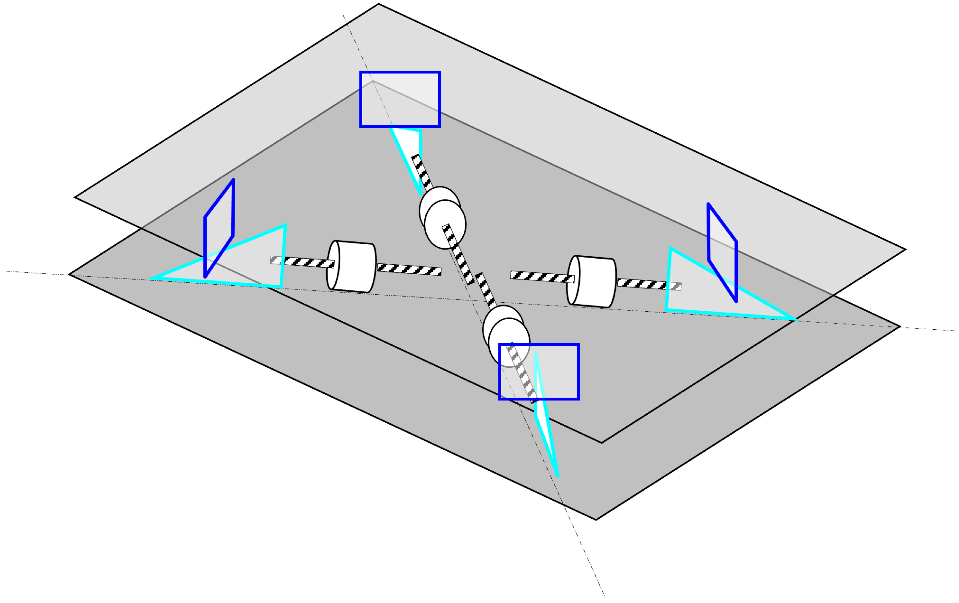
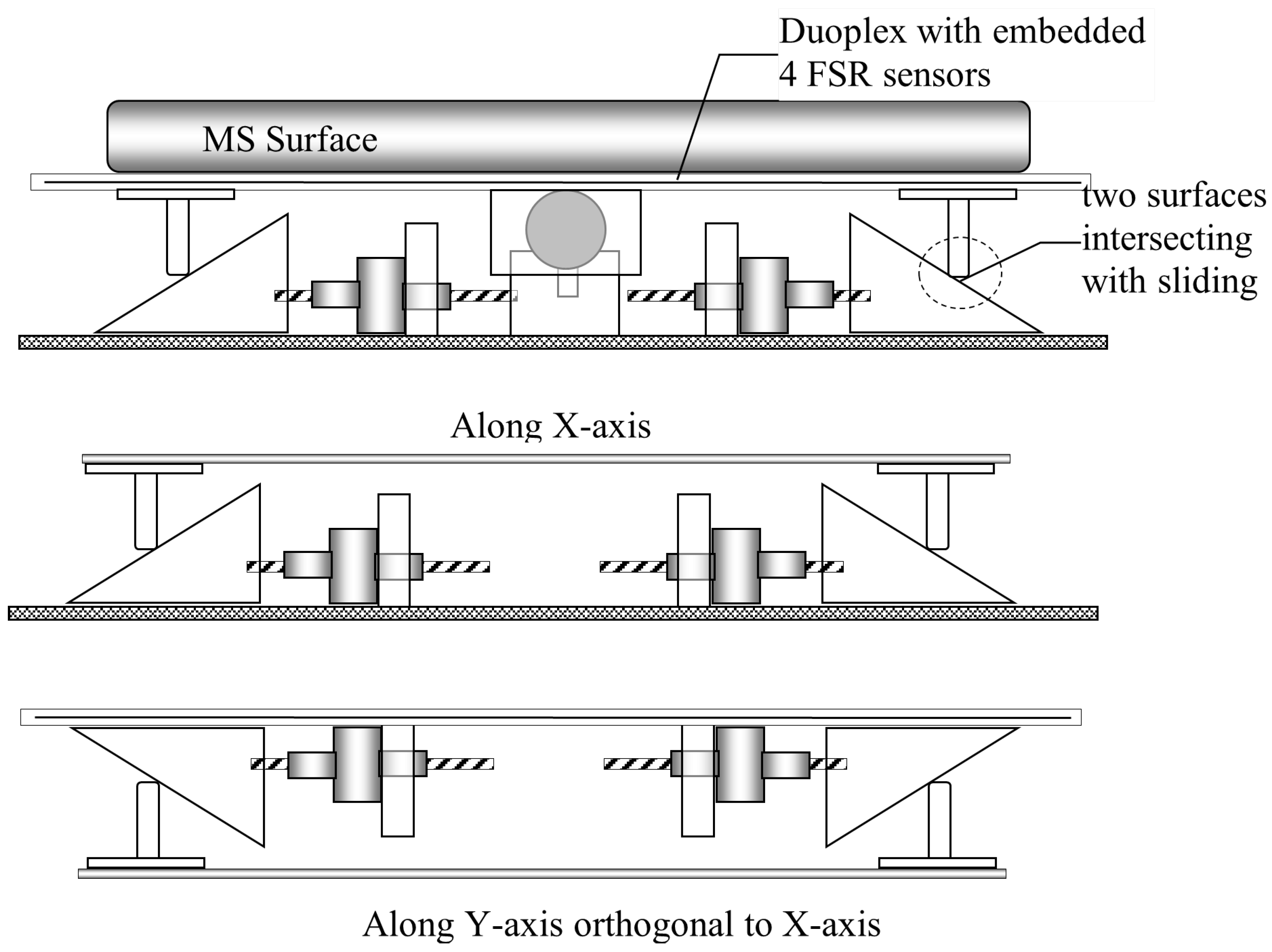
Our initial prototype implementation was based on using a voice coil, which was quickly found to be inadequate due to the high heat output and power consumption required to provide the static continuous force feedback in use. Instead, stepper motors were chosen to deliver continuous feedback without the drawbacks of the voice coil actuator design. The new configuration of the HAP builds on the knowledge we gathered during the second iteration stage of the project development. In addition, the stepper motor array configuration is more advanced, as it incorporates three-dimensional actuation as a basic functionality in its design. The initial setup can be seen in
Figure 9 and
Figure 10. The touch-sensitive surface of the tablet was set to be on top of the upper plate, which rests atop the movable sliding wedges that are independently controlled by each of the stepper motors, allowing precise movement control along the six degrees of freedom (6-DOF).
The stepper motors chosen were four of the 20DAM20D2B-K linear actuators by Portescap [
49]. The stepper motor does not rely on any gearing, as it internally converts rotary motion to linear motion via a rotating nut with a magnet and a lead screw. This actuator eliminates the need for other rotary-to-linear conversions such as belts and pulleys, rack and pinions, or external ball screws. Linear stepper motors also hold their linear position without power utilizing the detent torque of the can stack motor, reducing the power requirements of the system when not in operation. These were selected for their reasonable holding force of up to 20.9 N per actuator and their unenergized holding force of 11.1 N. This force meant that the device would not be noticeably affected by user input force and would allow the stepper motor uninterrupted actuation, given the weight of the tablet and finger resting force.
The clear advantage of captive linear actuators and the reason behind the decision to choose them over other technologies is their ability to sustain an unenergized holding force. This means we did not have to continuously power the motors, which translated to lesser energy use. Still, most important to our prototype is the fact that it eliminates overheating and seizing we experience with other technologies (voice coils, solenoids, etc.) when under heavy, repeated use. The step rate can be as quick as 2.5 ms per step, allowing for fast response with imperceptible delay. The linear actuators are powered individually by four L298N motor controllers. These were chosen for their ease of installation and wide availability. Four FSR 400 Force sensing resistors [
50] activate with as little as 0.1 N of force and have an analog response curve that allows for high-resolution feedback. The platform and the stepper-attached wedges are made from a clear acrylic that can be cut, shaped, and formed while staying relatively durable.
An Arduino Mega was used to communicate with the tablet as well as all motor controllers and FSRs. The Mega was chosen due to it being a relatively well-known platform with large online support. The software builds on top of the three-key version by expanding to a 12-keycap layout while continuing to allow for virtual keycap rendering with integrated force sensing and multidimensional actuation. A schematic diagram of the perspective projection view is shown in
Figure 9. The haptic actuation platform design allows manipulation of the touchscreen surface of the Surface Go tablet placed over the volumetric haptic actuation interface to any angle, allowing 6-DOF movements. Using stepper motors minimizes rotation energy to translate the multi-axis positioning system. Displacements are limited only by the length of the stepper motor shaft.
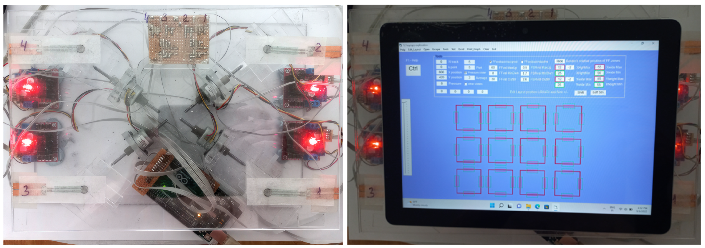
Figure 11 shows the final prototype that was used during the user study.
The design configuration of the demonstrator prototype allows for technical keycap rendering performance far beyond the values previously documented as necessary for keycap simulation, which means that, in the current configuration, we were not limited regarding ideal virtual keycap rendering performance. Using four stepper motors allows for fast performance in combination with the relatively light tablet device (522 g). The current configuration allows for a maximum reflective force of 20 N with a linear vertical speed of 3.81 mm per second. Lateral XY movements are limited to +/−10 mm by a retaining frame. The prototype can reproduce angular slopes with up to 16 degrees of incline in any XY direction in combination with a maximum displacement of 26.5 mm along the Z-axis.
6. Software
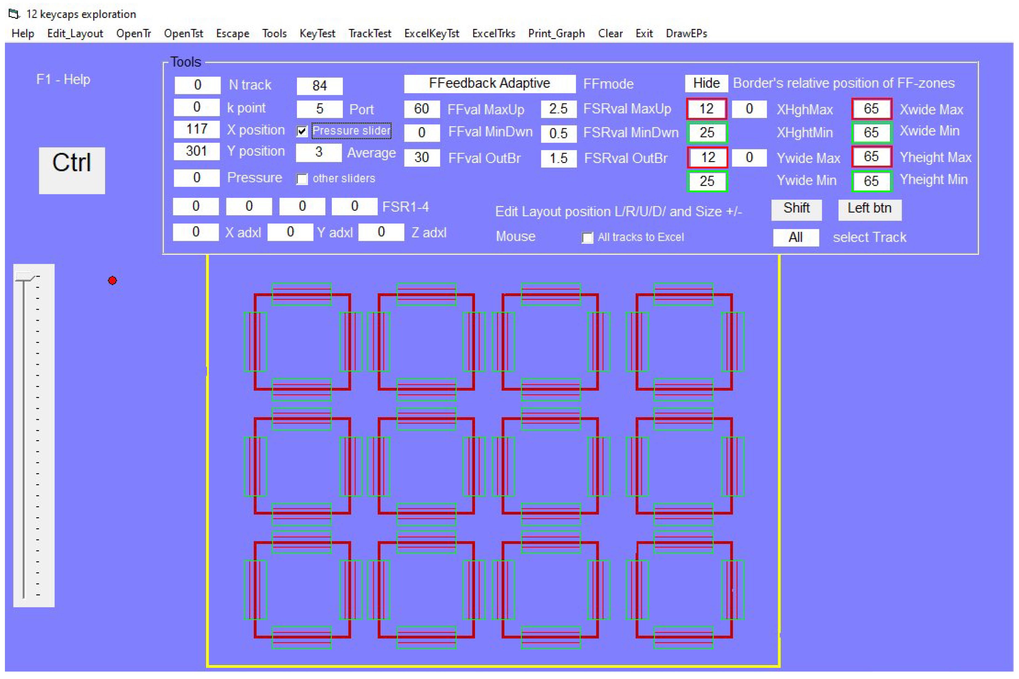
Figure 12 shows the final software interface adapted for the MS Surface Go. The software communicates with the embedded Arduino to activate the four steppers’ multidimensional force feedback (FF) control to explore the 12-keycap virtual button arrangement—position, visualization, and scale of keycaps; in addition, the active FF zones are fully adjustable.
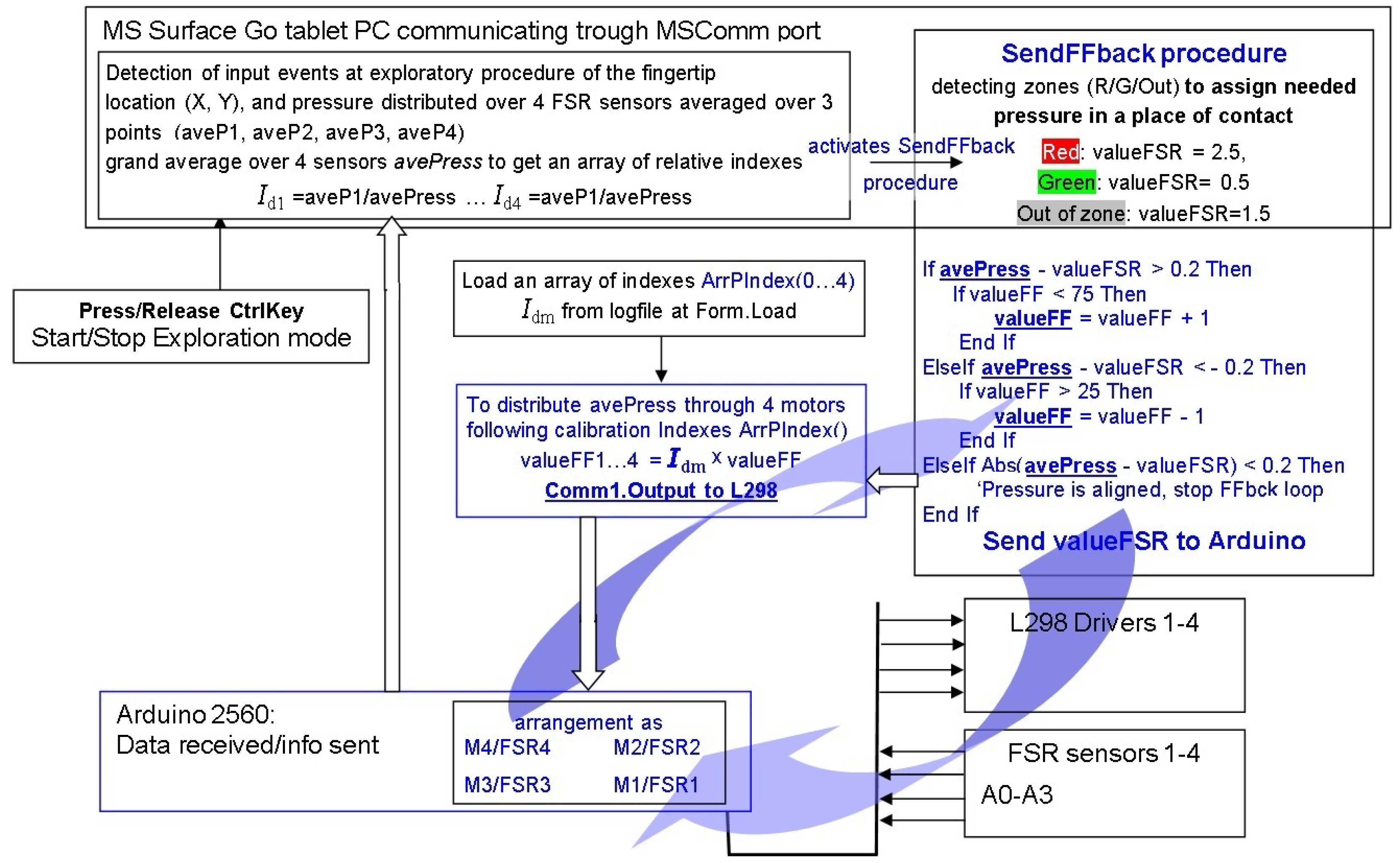
As shown in
Figure 13, the Arduino continuously sends control signals to the four motor drivers to support the value of valFSR assigned according to the detected zones of the fingertip location. It is evaluated in the SendFFdbck procedure and distributed as a response among the four measurement points according to the array of calibration indices. It usually corresponds to neutral (the out-of-zone blue areas), a light pressure value equal to 1.5 V, and a value in the middle of the dynamic range for each pressure sensor measurement. The Surface Go tablet then sends valFSR to the Arduino only when the finger position crosses or enters the specific zone and/or the applied pressure changes. The data from the FSR sensors are read from the Arduino and sent to the Surface Go tablet to be evaluated and immediately processed to activate the response of the haptic actuation platform according to the expected pressure along the track of exploration of the volumetric keycap profile.
Moreover, rendering looks smoother when measured pressure values are averaged sequentially over thee values. The multi-dimensional array of indices [
42], according to previous calibrations, is stored in a log file. When a fingertip crosses assigned zones during interaction with the virtual assembly of keycaps, a specific profiling function of pressure deviation in a force-feedback adaptive (FFadaptive) or force-feedback assigned (FFassigned) mode is activated. This function uses the keycap exploration data to set a specific position for each stepper motor to adequately adjust the height and angle of the display dependent on the position of the finger in relation to the virtual keycap.
FFadaptive uses additional pressure sensing data to adjust the profile to apply additional force based on input pressure. FFassigned does not take the pressure feedback into account and assumes feedback to be independent of the pressure applied by the user. As we can assume that each keycap is nearly identical in its physical profile, such a solution allows the demonstrator software expansion into a keyboard with 12 keycaps or beyond.
7. Design and UX Performance Test of the 12 Virtual Keycaps
At this stage, the software is considered ready for user testing. We conducted three UX test rounds which included a minimum of three matrix iteration rounds. Participants were gathered by posting a call for participants on local social media groups with a general brief statement in the following format: “Looking for participants in the local area for a user study on haptic technology. Movie ticket will be provided for participation”. Seven participants were recruited during this call for participants. The participants were asked to perform three tasks in which data were gathered.
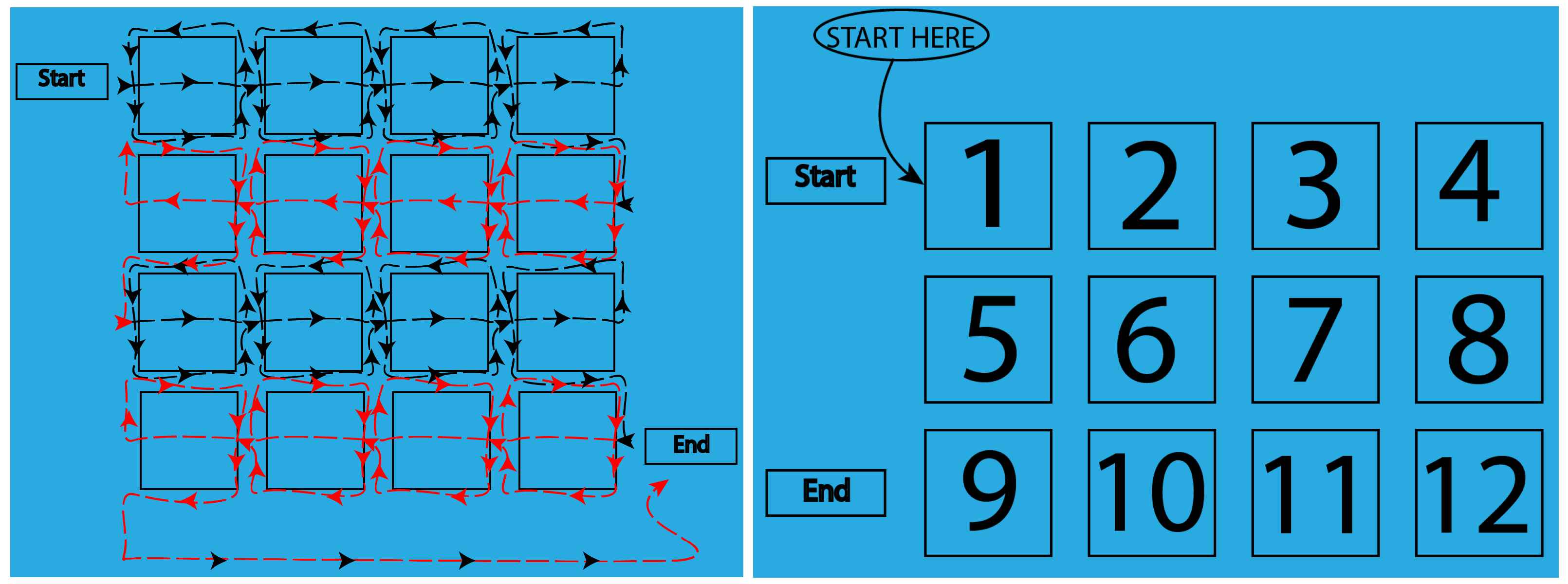
The first task was to perform a general exploration of the 12 keycaps. It was achieved with two different types of haptic force feedback, without visual feedback with their eyes closed. The keycaps were presented in a random order. Before they began exploration, the task was explained in detail. The sketches shown in
Figure 14 were provided to help the participants better understand their task. Before the test, all participants confirmed that they understood the task clearly.
Figure 14 displays the layout of the twelve keycaps.
Participants were instructed to press the “Start” button and explore the keycaps by dragging their finger down the center of the keycap and then exploring the edges before continuing to the next keycap. Once the exploration task was completed, the participants were asked to press the “End” button to complete the test and begin the next task.
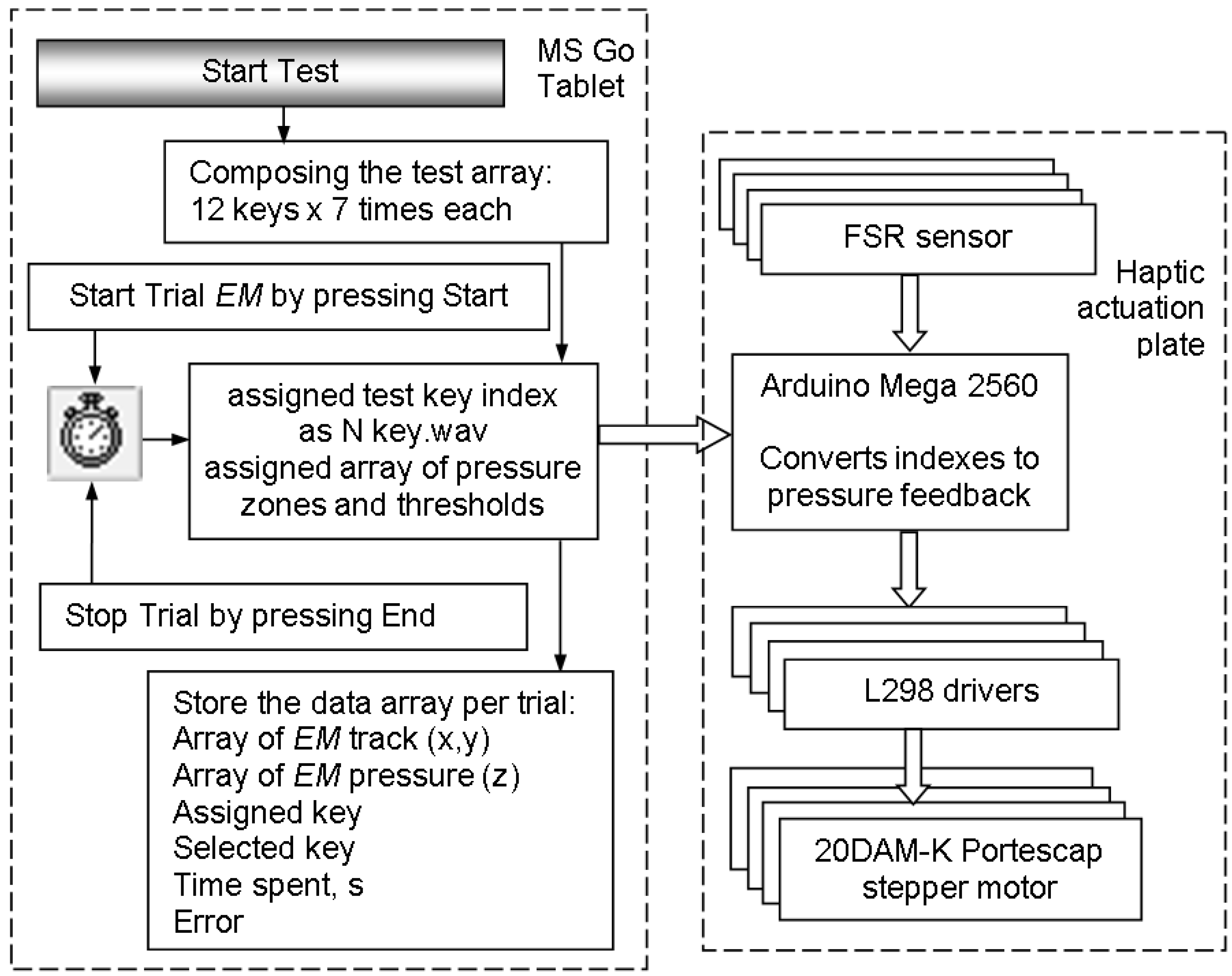
Figure 15 includes a flow chart of the research procedure conducted as part of the participant study. As soon as we started the experiment, the test array was be composed in memory. The assigned task wasthen be pulled from the array, and an associated wav audio file was played. The participant then pressed the start button and began exploring from the start position. Each individual trial ended as soon as the participant pressed the end button. During exploration, the haptic actuation plate adaptively adjusted actuation feedback as needed. With the trial completed, all associated data were stored.
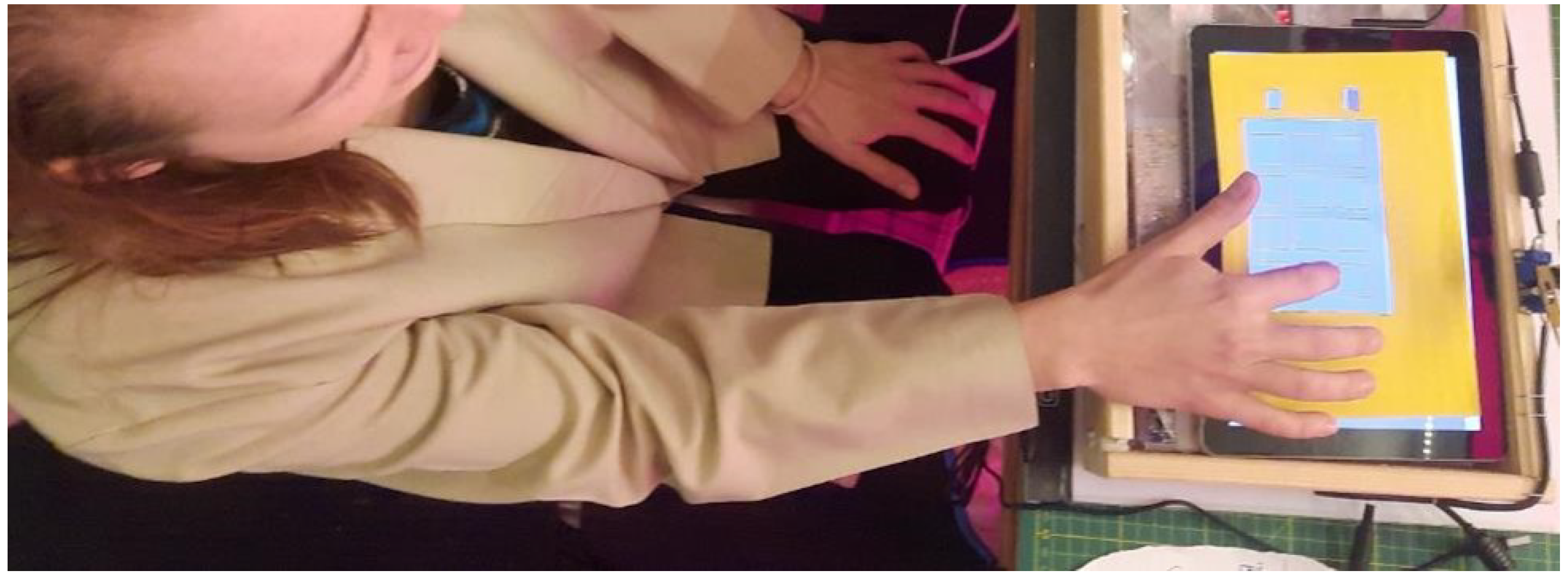
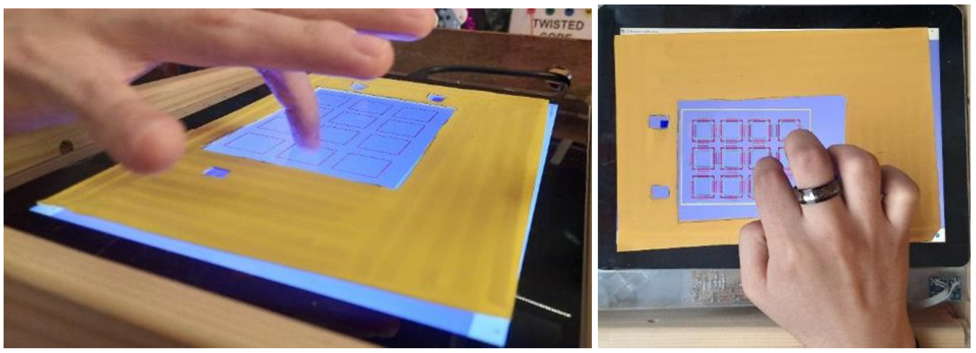
Figure 16 shows an above view of a participant with their eyes closed exploring the surface as instructed.
Figure 17 illustrates a user’s hand during the exploration stage. All unnecessary onscreen objects (frame of tools and system taskbar), as well as a keycap layout and zones of force feedback, were hidden during the test. A foam border was placed to keep participants from navigating away from the designated region of the virtual keyboard in absence of visual feedback.
In the next two tasks, a specific number was indicated on the tablet while a participant performed their best with their eyes closed to find a given keycap on the virtual keyboard. Participants were provided with the sketch shown in
Figure 14 to understand the placement of the virtual keys. They were asked to press the start button and then place their finger at the starting point, before exploring the keypad with their eyes closed. Once they believed they found the keycap that was announced, they lifted their finger off the display and pressed the end button before starting the next prompt. This was repeated 84 times (seven trials per keycap) for each of the two configurations that consist of a thin and thick edge profile.
8. The Results of the User Study on Navigation within the 12 Virtual Keycaps
The study proceeded without any issues. In this section, we discuss participant performance during the experiment, as well as their subjective impression of the performance evaluation of the volumetric haptic feedback.
8.1. User Performance Detecting Specific Keycap Location
All participants found the initial exploratory task understandable and easy to follow. Participants were able to follow the task as indicated by
Figure 16 and
Figure 17 that show participants’ exploratory behavior. The presented data show occasional deviation, but overall, the task was accomplished proficiently.
As for the task in which participants were asked to find a specific keycap, two modes of haptic edge rendering were used without participants’ knowledge. These modes were named thin and thick in reference to the size of the force feedback zones. These feedback zones were marked as red when the actuation platform moved upwards against fingertip pressure, thus enhancing the pressure felt at the point of contact, and green when the actuation platform moved downwards, thereby releasing the pressure on the fingertip.
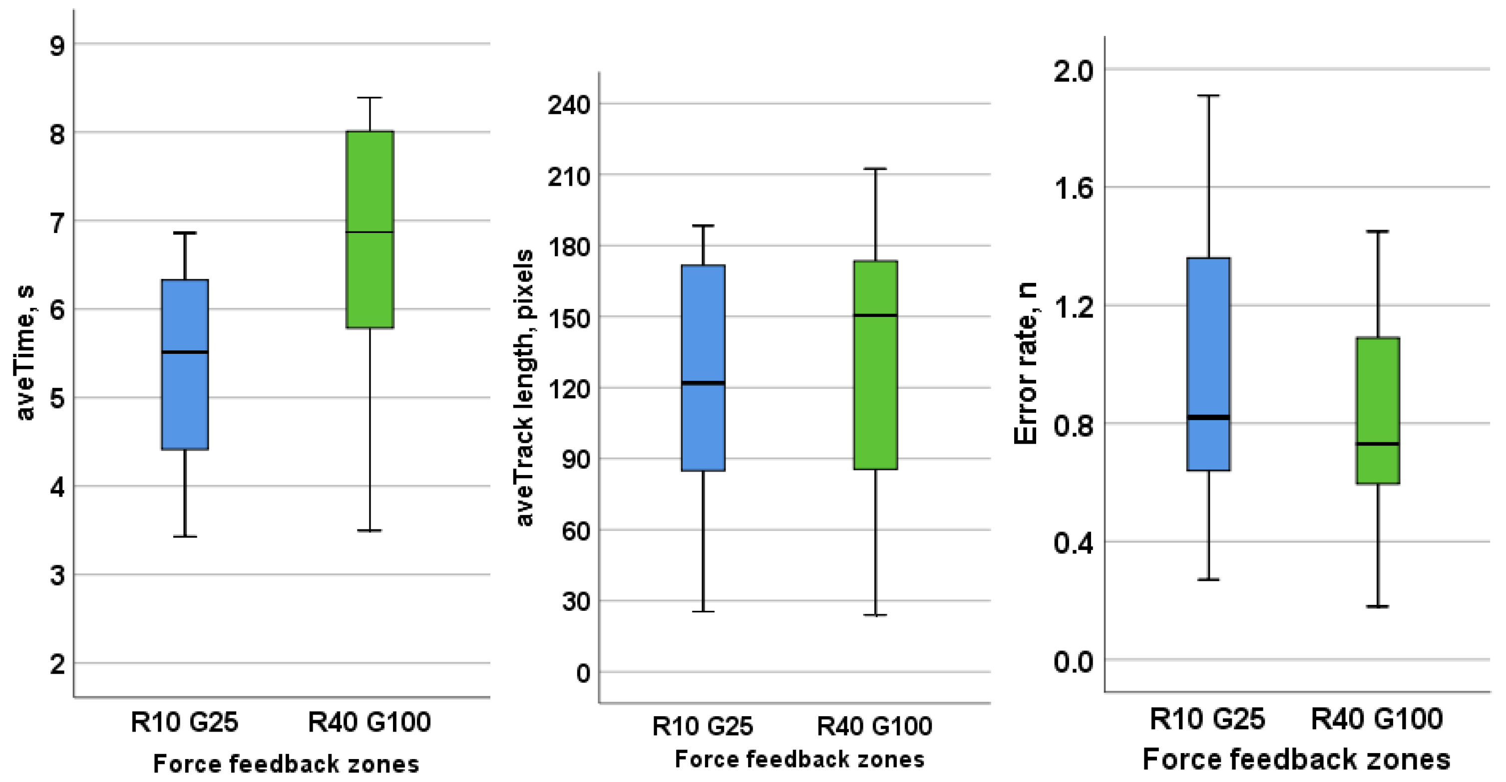
The graphs in
Figure 18 display a clear difference between the thickness of the force feedback zones. The thinner feedback zones (R10 G25) show that participants accomplished their task quickly but at the cost of lower accuracy in comparison with the thicker feedback zone (R40 G100). The letter R refers to the red zone, and the letter G refers to the green zones as can be seen in
Figure 12. Each zone is positioned along the four edges of each keycap square. The number following the letter refers to the width in pixels of the zone.
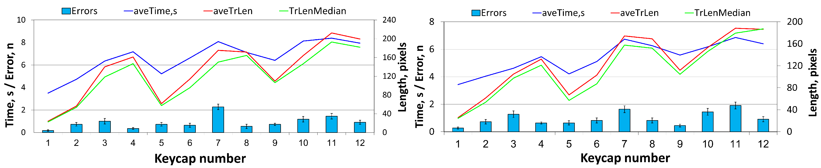
Figure 19 illustrates a clear pattern for both thin and think feedback zones. Errors and time to accomplish task both increase as participants move away from the start position. This is to be expected as participants must rely more on only their sense of touch as they move further from the start position. Although we observed an increased error rate at further distances, the error rate was still quite low and relevant to the extent of the test.
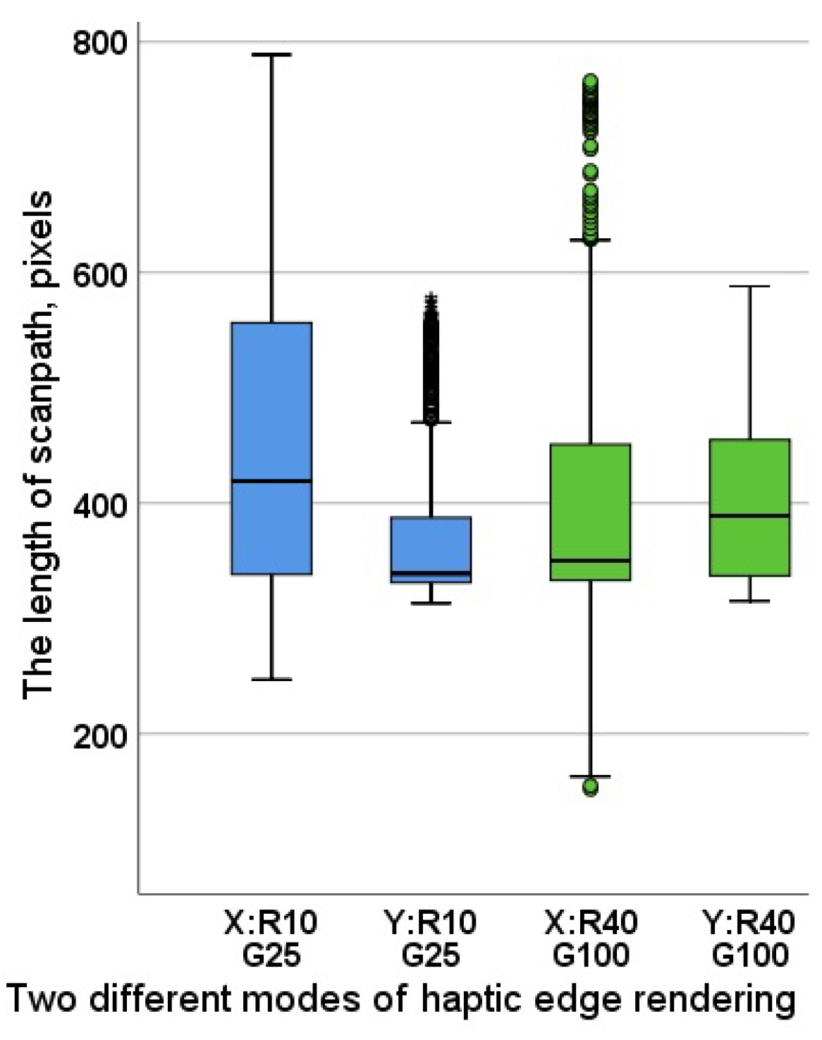
Boxplots in
Figure 20 represent scanpaths that complement
Table 2 that shows the
t-Test results; significant difference between the given pairs with a
p-value of <0.05 are also displayed. The given position of the highlighted pairs suggests that the difference is most apparent as distance increases and for keycaps surrounded by other keys. Smaller whiskers indicate higher consistency and lower variability in the data. Longer whiskers, such of that of ThinX, indicate less inconsistency in user behavior. Overall, we might be able to infer that the combination of thin boundaries on the X-axis and thick boundaries on the Y-axis likely provide the best performance.
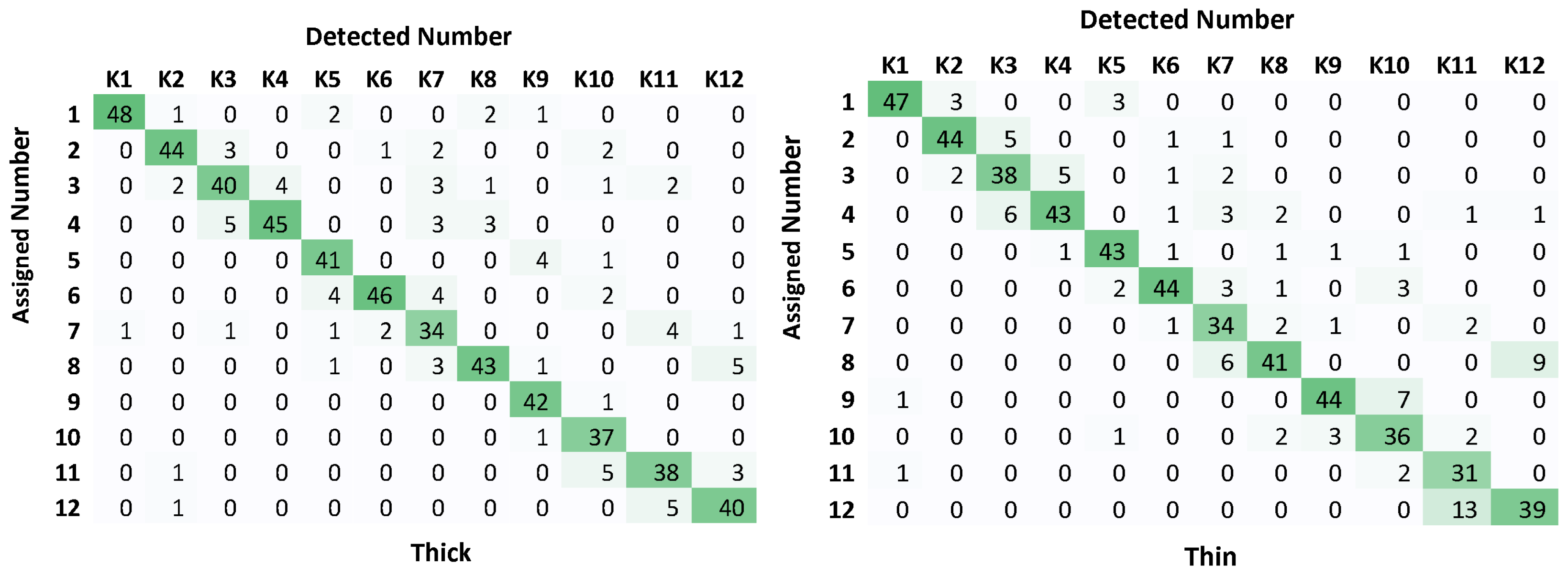
The confusion matrices in
Figure 21 further illustrate that participants were rarely confused about a given task. Shades of green near desired responses indicate lower confusion, while responses far from desired responses indicate a higher likelyhood that a participant did not solve the given task properly. With the vast majority of errors occurring near the expected keycap, we can confidently say that the participants understood and were able to complete the tasks as instructed.
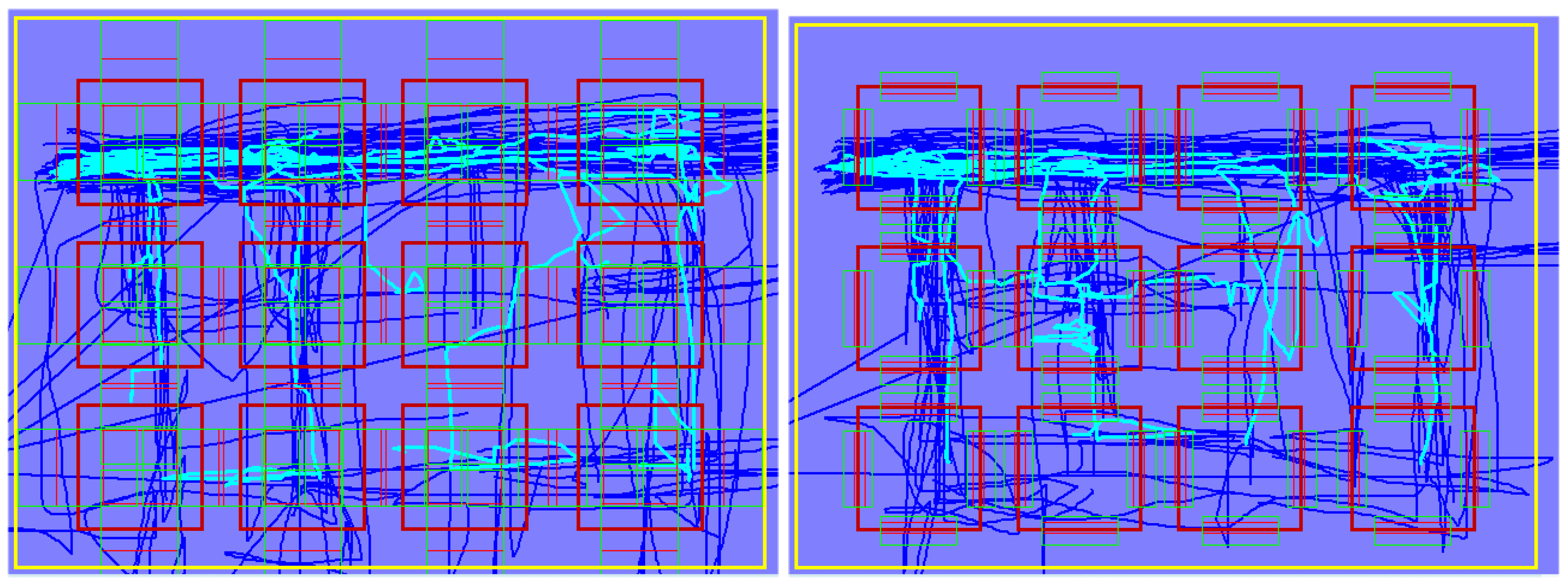
Figure 22 illustrates an example of the Eps as scanpaths users took to reach selected keycaps when navigating to a random keycap to be found (right thin, left thick). As participants explored keycaps on the bottom right, they relied increasingly on exploring the edges, whereas on the top left, in the vicinity of the starting point, users spent less time exploring and seemed more confident in their response.
Figure 23 shows similar behavior, as more effort is spent exploring keycaps further from the starting point to ensure the correct keycap is found.
Figure 24 displays the pressure variation applied at the LTE mode while detecting the specific virtual keycap location. Participants applied a pressure consistent twith the amount of pressure they applied druing light touch when exploring the plastic keycaps. While pressure was recorded throughout all tests, the impact during exploratory behavior was negligible. That is, the participants relied on counting the number of raised keycaps, i.e., volumetric features presented and recognized as the entire shape.
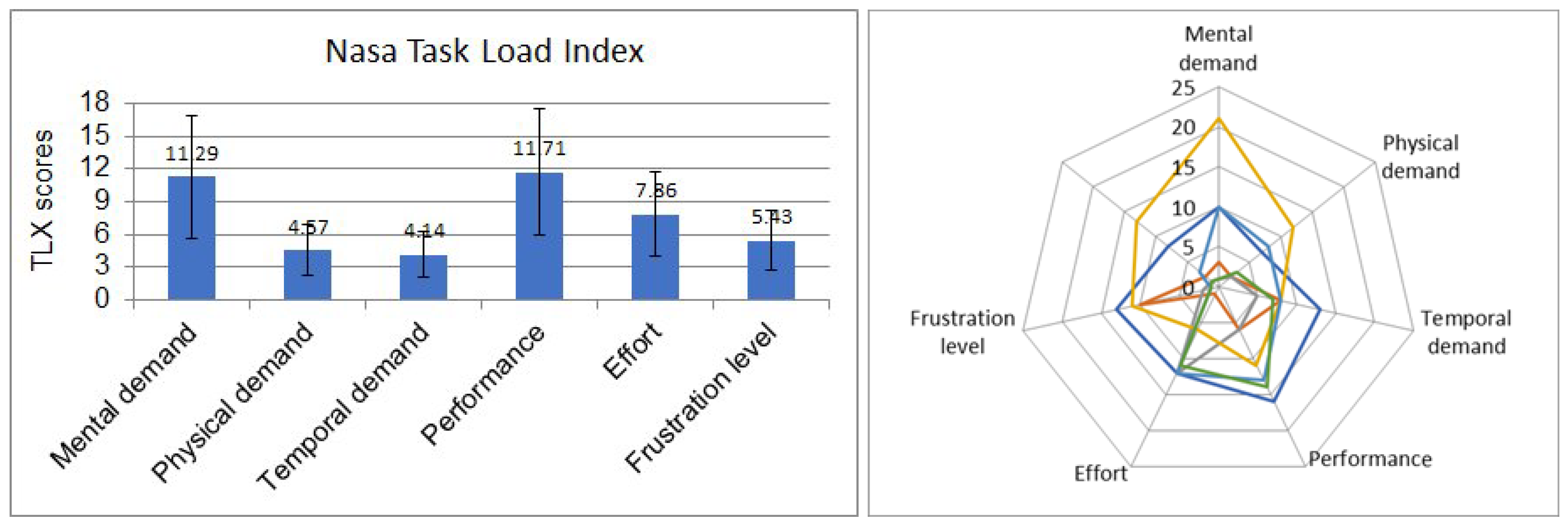
8.2. Subjective Evaluation of the Volumetric Haptic Enhancement
Figure 25 summarizes the compiled average of Nasa TLX responses. As expected, participants showed an exceptionally low physical demand, as well as relatively low frustration levels, along with a reasonably low amount of effort required to complete the task. Participants felt the task was short and did not have to spend too much time completing the task. We also observed a slightly above-average feeling of positive performance, as well as slightly above-average mental demand. These data indicate that while the participants felt that the task was easy to follow and approachable, the reduced performance could be related to users needing to focus on the given task. It may be, in part, due to all participants being unfamiliar with the device. It is possible that with daily use, or with open eyes, users would find the interaction with the device natural.
Average participant age was around 30 years old. Of those who disclosed gender in their questionnaire data, 50% were female, and 50% were male. All participants, without exception, responded that they perceived the key locations based on volumetric feedback. When asked how well it was perceived, the average score was 2.9 out of 5. Open-ended feedback was generally positive, with responses such as “It is an emerging technology and the experiment was very user friendly”, or “It could improve immersion experience to a game, it could help people who have trouble with their sight”.
We find that according to participant responses, the prototype was most likely highly effective at conveying volumetric feedback as intended.
9. Discussion
Being able to introduce clearly perceptible volumetric haptics to any surface with the use of four stepper motors leads us closer to a reality where we could see volumetric haptics integrated into consumer devices. Many of the existing techniques for volumetric feedback have their own issues, but most importantly, they are overly complex to manufacture at scale, often with an excess number of parts that are difficult to implement in consumer devices.
A wide variety of enhanced feedback can likely be applied to many aspects of our daily lives. In-car capacitive displays would be enhanced with such a design to reduce the amount of time a person has to look at a display as they navigate it through touch. At the moment, research shows that physical buttons are still the preferred method of interaction when it comes to safety [
51,
52]. Additional tactile information could even be presented via the steering wheel, helping to augment the driving experience with volumetric cues. Displays with volumetric haptics may help a person to better understand the details of a map, enhancing areas that may have increased elevation or curvature. It could help those surveying an area for construction to better communicate the challenges for a given region or terrain, without necessarily having to incorporate it into AR/VR environments, allowing potential users to interact with the interface naturally without the need to wear cumbersome additional hardware. The enhancement of touch feedback via volumetric feedback has the opportunity to improve human interaction among a variety of existing technologies and interfaces.
While much of our culture is visual-centric, we must remember that it is through haptics that we interact with and communicate through our devices. Research has already shown that haptics plays an important role in how our motor and perceptual skills develop from an early age [
53]. Unfortunately, many high-fidelity haptic technologies that exist are priced beyond access of most consumers and even organizations. Haptic technologies will continue to evolve to bring us more accessible immersive rich experiences. For this to happen, much like any technology, strides need to take place in design simplicity that can lead to lower cost [
54] and easier manufacturing, and a subsequent production of platforms that we might one day take for granted as part of the visual displays we already find integrated in our daily lives.
Participants enjoyed the novel volumetric feedback, and saw the value it can provide to existing displays. The research is limited in the granularity of the feedback due to the use of stepper motors. We find that the demo built on the stepper motor construction has a great potential as it significantly reduces energy consumption. Yet a noticeable drawback of the granularity is tied to the size of each step provided by the motor. This, of course, can likely be adjusted using adaptive fast switching to a micro-stepping mode when necessary.
The current demo is large, but micro stepper motors are readily available on the market having been common in the camera market to control actions such as auto-focusing on a set of attached lenses. Another option would be the use of variably adjustable motors or voice coils, with the side effect of introducing calibration and overheating challenges.
We did not analyze all the features collected from the recorded tracks over the layout of keys, only focusing on the linear parameters. For this reason, the signature of the captured three-dimensional parameters, which includes applied pressure of exploration, should be further analyzed to understand the exploratory behavior of participants.
A possible future direction would be to include such a technology into a haptic case in which a phone or tablet can be placed into. With the advent of flexible displays and the enhanced usage of motors designed to open and close a display, it may be possible to enhance tactile feedback and exploratory haptics using existing actuators in a display. Furthermore, as flexible displays become increasingly available, this approach to volumetric haptics could potentially be integrated within a display.
Much of the current focus of volumetric haptics is focused on VR and AR environments [
55]. A fascinating suggestion is the idea that volumetric haptics may be a necessity in the field of tele-surgery, where a surgeon needs precise feedback to operate precision tools remotely [
56,
57,
58]. Our solution in itself is not geared towards such high-risk scenarios, but one could imagine that the techniques in this paper could be scaled with precision components that would allow complation of such a task.
Part of any of these endeavors is the necessity to develop the methods to capture feelable data along with the algorithms that enable the accurate physical representations to be presented and felt [
59]. Our data collection device is an example of a simplified rig that can be used for such a task. As the primary active component is that of a pressure sensor, one can imagine how that might be used to capture data remotely to then be presented over a volumetric interface.
Without exception, all participants were able to explore and feel the exploratory features of a virtual set of keypads. Still, there is room to improve the granularity of the feedback in both hardware adjustments and software settings. For our own research goals, we find the results to be a milestone as it is a concept that can be quickly replicated via rapid prototyping at a relatively low cost.
10. Conclusions
In this paper, we effectively demonstrated a prototype implementation of a universal volumetric haptic actuation platform. An initial user experiment helped solidify the potential of the platform design. This design was made with cost and adaptability in mind. Our goal of simulating the static 3D features of an input interface was possible to complete with the help of initial data collection to capture the features of keycaps. The use of readily available stepper motors in a diagonal cross configuration allowed us a quickly change in the position of the surface in a manner that successfully rendered the volumetric features of keyboard keycaps.
We primarily navigated and communicated through our handheld devices via the use of haptics. By introducing distinguishable volumetric haptic feedback, this experience can be vastly improved. The benefit that comes first to mind is the easing of navigation through software menus as well as the task of typing. The use of volumetric feedback may even allow for the implementation of natural, volumetric gestures. It may provide non-visual in-pocket control schemes, or even new ways to interact with and communicate with friends and family. With the introduction of widely available volumetric feedback techniques, we can open up mobile platforms to a new creative paradigm of communication design with possibilities we have yet to dream of.


