
Development of a Time-Gated Epithermal Neutron Spectrometer for Resonance Absorption Measurements Driven by a High-Intensity Laser
 , , , and
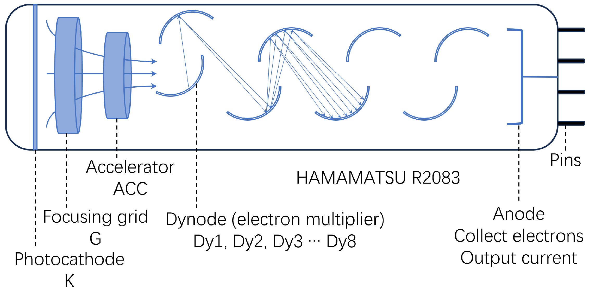
Abstract
:1. Introduction
2. Materials and Methods
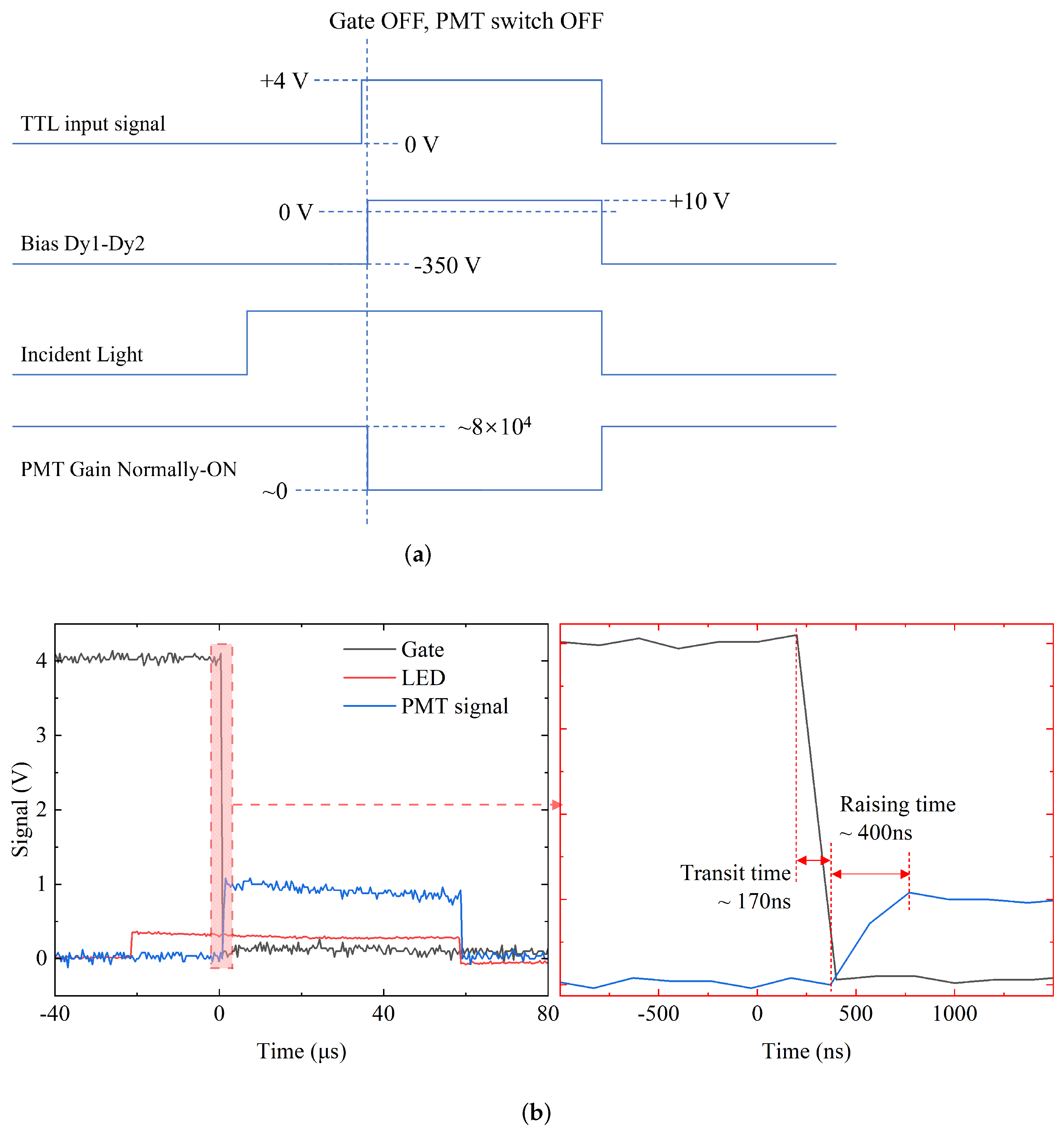
2.1. Development of the Time-Gated PMT
2.2. Experimental Demonstration Using Laser-Driven Neutrons
3. Results
3.1. The Evaluation of X-ray Cut-Off Ratio of the Time-Gated Detector
3.2. Demonstration for Neutron Resonance Measurement
4. Discussion
5. Conclusions
Author Contributions
Funding
Informed Consent Statement
Data Availability Statement
Acknowledgments
Conflicts of Interest
Abbreviations
| LDNS | Laser-driven neutron source |
| PMT | Photomultiplier tube |
| TOF | Time-of-flight |
| ETG | Electrical time-gating |
| HDPE | High-density polyethylene |
References
- Groeger, S.; Bison, G.; Knowles, P.E.; Wynands, R.; Weis, A. Laser-pumped cesium magnetometers for high-resolution medical and fundamental research. Sens. Actuators A Phys. 2006, 129, 1–5. [Google Scholar] [CrossRef]
- Yuan, V.; Bowman, J.D.; Funk, D.; Morgan, G.; Rabie, R.; Ragan, C.; Quintana, J.; Stacy, H. Shock temperature measurement using neutron resonance spectroscopy. Phys. Rev. Lett. 2005, 94, 125504. [Google Scholar] [CrossRef] [PubMed]
- Higginson, D.; McNaney, J.; Swift, D.; Bartal, T.; Hey, D.; Kodama, R.; Le Pape, S.; Mackinnon, A.; Mariscal, D.; Nakamura, H.; et al. Laser generated neutron source for neutron resonance spectroscopy. Phys. Plasmas 2010, 17, 100701. [Google Scholar] [CrossRef]
- Mirani, F.; Maffini, A.; Passoni, M. Laser-driven neutron generation with near-critical targets and application to materials characterization. Phys. Rev. Appl. 2023, 19, 044020. [Google Scholar] [CrossRef]
- Brenner, C.; Mirfayzi, S.; Rusby, D.; Armstrong, C.; Alejo, A.; Wilson, L.; Clarke, R.; Ahmed, H.; Butler, N.; Haddock, D.; et al. Laser-driven x-ray and neutron source development for industrial applications of plasma accelerators. Plasma Phys. Control. Fusion 2015, 58, 014039. [Google Scholar] [CrossRef]
- Lancaster, K.; Karsch, S.; Habara, H.; Beg, F.; Clark, E.; Freeman, R.; Key, M.; King, J.; Kodama, R.; Krushelnick, K.; et al. Characterization of 7Li(p,n)7 Be neutron yields from laser produced ion beams for fast neutron radiography. Phys. Plasmas 2004, 11, 3404–3408. [Google Scholar] [CrossRef]
- Yogo, A.; Lan, Z.; Arikawa, Y.; Abe, Y.; Mirfayzi, S.; Wei, T.; Mori, T.; Golovin, D.; Hayakawa, T.; Iwata, N.; et al. Laser-driven neutron generation realizing single-shot resonance spectroscopy. Phys. Rev. X 2023, 13, 011011. [Google Scholar] [CrossRef]
- Alejo, A.; Krygier, A.; Ahmed, H.; Morrison, J.; Clarke, R.; Fuchs, J.; Green, A.; Green, J.; Jung, D.; Kleinschmidt, A.; et al. High flux, beamed neutron sources employing deuteron-rich ion beams from D2O-ice layered targets. Plasma Phys. Control. Fusion 2017, 59, 064004. [Google Scholar] [CrossRef]
- Günther, M.; Rosmej, O.; Tavana, P.; Gyrdymov, M.; Skobliakov, A.; Kantsyrev, A.; Zähter, S.; Borisenko, N.; Pukhov, A.; Andreev, N. Forward-looking insights in laser-generated ultra-intense γ-ray and neutron sources for nuclear application and science. Nat. Commun. 2022, 13, 170. [Google Scholar] [CrossRef]
- Arikawa, Y.; Morace, A.; Abe, Y.; Iwata, N.; Sentoku, Y.; Yogo, A.; Matsuo, K.; Nakai, M.; Nagatomo, H.; Mima, K.; et al. Demonstration of efficient relativistic electron acceleration by surface plasmonics with sequential target processing using high repetition lasers. Phys. Rev. Res. 2023, 5, 013062. [Google Scholar] [CrossRef]
- Clark, E.; Krushelnick, K.; Zepf, M.; Beg, F.; Tatarakis, M.; Machacek, A.; Santala, M.; Watts, I.; Norreys, P.; Dangor, A. Energetic heavy-ion and proton generation from ultraintense laser-plasma interactions with solids. Phys. Rev. Lett. 2000, 85, 1654. [Google Scholar] [CrossRef] [PubMed]
- Maksimchuk, A.; Gu, S.; Flippo, K.; Umstadter, D.; Bychenkov, V.Y. Forward ion acceleration in thin films driven by a high-intensity laser. Phys. Rev. Lett. 2000, 84, 4108. [Google Scholar] [CrossRef] [PubMed]
- Snavely, R.; Key, M.; Hatchett, S.; Cowan, T.; Roth, M.; Phillips, T.; Stoyer, M.; Henry, E.; Sangster, T.; Singh, M.; et al. Intense high-energy proton beams from petawatt-laser irradiation of solids. Phys. Rev. Lett. 2000, 85, 2945. [Google Scholar] [CrossRef]
- Passoni, M.; Bertagna, L.; Zani, A. Target normal sheath acceleration: Theory, comparison with experiments and future perspectives. New J. Phys. 2010, 12, 045012. [Google Scholar] [CrossRef]
- Yogo, A.; Mima, K.; Iwata, N.; Tosaki, S.; Morace, A.; Arikawa, Y.; Fujioka, S.; Johzaki, T.; Sentoku, Y.; Nishimura, H.; et al. Boosting laser-ion acceleration with multi-picosecond pulses. Sci. Rep. 2017, 7, 42451. [Google Scholar] [CrossRef] [PubMed]
- Macchi, A.; Borghesi, M.; Passoni, M. Ion acceleration by superintense laser-plasma interaction. Rev. Mod. Phys. 2013, 85, 751. [Google Scholar] [CrossRef]
- Roth, M.; Jung, D.; Falk, K.; Guler, N.; Deppert, O.; Devlin, M.; Favalli, A.; Fernandez, J.; Gautier, D.; Geissel, M.; et al. Bright laser-driven neutron source based on the relativistic transparency of solids. Phys. Rev. Lett. 2013, 110, 044802. [Google Scholar] [CrossRef]
- Kleinschmidt, A.; Bagnoud, V.; Deppert, O.; Favalli, A.; Frydrych, S.; Hornung, J.; Jahn, D.; Schaumann, G.; Tebartz, A.; Wagner, F.; et al. Intense, directed neutron beams from a laser-driven neutron source at PHELIX. Phys. Plasmas 2018, 25, 053101. [Google Scholar] [CrossRef]
- Mirfayzi, S.; Yogo, A.; Lan, Z.; Ishimoto, T.; Iwamoto, A.; Nagata, M.; Nakai, M.; Arikawa, Y.; Abe, Y.; Golovin, D.; et al. Proof-of-principle experiment for laser-driven cold neutron source. Sci. Rep. 2020, 10, 20157. [Google Scholar] [CrossRef]
- Zimmer, M.; Scheuren, S.; Kleinschmidt, A.; Mitura, N.; Tebartz, A.; Schaumann, G.; Abel, T.; Ebert, T.; Hesse, M.; Zähter, Ş.; et al. Demonstration of non-destructive and isotope-sensitive material analysis using a short-pulsed laser-driven epi-thermal neutron source. Nat. Commun. 2022, 13, 1173. [Google Scholar] [CrossRef]
- Copley, J.R.; Udovic, T.J. Neutron time-of-flight spectroscopy. J. Res. Natl. Inst. Stand. Technol. 1993, 98, 71. [Google Scholar] [CrossRef] [PubMed]
- Kar, S.; Green, A.; Ahmed, H.; Alejo, A.; Robinson, A.; Cerchez, M.; Clarke, R.; Doria, D.; Dorkings, S.; Fernandez, J.; et al. Beamed neutron emission driven by laser accelerated light ions. New J. Phys. 2016, 18, 053002. [Google Scholar] [CrossRef]
- Bencardino, R.; Eberhardt, J.E. Development of a fast-neutron detector with silicon photomultiplier readout. IEEE Trans. Nucl. Sci. 2009, 56, 1129–1134. [Google Scholar] [CrossRef]
- Roecker, C.; Bernstein, A.; Bowden, N.; Cabrera-Palmer, B.; Dazeley, S.; Gerling, M.; Marleau, P.; Sweany, M.; Vetter, K. Design of a transportable high efficiency fast neutron spectrometer. Nucl. Instrum. Methods Phys. Res. Sect. A Accel. Spectrom. Detect. Assoc. Equip. 2016, 826, 21–30. [Google Scholar] [CrossRef]
- Abe, Y.; Nakajima, N.; Sakaguchi, Y.; Arikawa, Y.; Mirfayzi, S.; Fujioka, S.; Taguchi, T.; Mima, K.; Yogo, A.; Nishimura, H.; et al. A multichannel gated neutron detector with reduced afterpulse for low-yield neutron measurements in intense hard X-ray backgrounds. Rev. Sci. Instrum. 2018, 89, 10I114. [Google Scholar] [CrossRef] [PubMed]
- Bennett, R.; Schwenker, R. Performance of a Pulsed 6292 Photomultiplier. Rev. Sci. Instrum. 1959, 30, 836–837. [Google Scholar] [CrossRef]
- De Martini, F.; Wacks, K.P. Photomultiplier Gate for Stimulated-Spontaneous Light Scattering Discrimination. Rev. Sci. Instrum. 1967, 38, 866–868. [Google Scholar] [CrossRef]
- De Marco, F.; Penco, E. Pulsed photomultipliers. Rev. Sci. Instrum. 1969, 40, 1158–1160. [Google Scholar] [CrossRef]
- Schulman, M.B. Gating circuit for linear-focused photomultiplier. Rev. Sci. Instrum. 1989, 60, 1264–1266. [Google Scholar] [CrossRef]
- Lee, S.; Lee, M.S.; Won, J.Y.; Lee, J.S. Performance of a new accelerating-electrode-equipped fast-time-response PMT coupled with fast LGSO. Phys. Med. Biol. 2018, 63, 05NT03. [Google Scholar] [CrossRef]
- Bristow, M.P.; Bundy, D.H.; Wright, A.G. Signal linearity, gain stability, and gating in photomultipliers: Application to differential absorption lidars. Appl. Opt. 1995, 34, 4437–4452. [Google Scholar] [CrossRef]
- Yogo, A.; Mirfayzi, S.R.; Arikawa, Y.; Abe, Y.; Wei, T.; Mori, T.; Lan, Z.; Hoonoki, Y.; Golovin, D.O.; Koga, K.; et al. Single shot radiography by a bright source of laser-driven thermal neutrons and X-rays. Appl. Phys. Express 2021, 14, 106001. [Google Scholar] [CrossRef]
- Shibata, K.; Iwamoto, O.; Nakagawa, T.; Iwamoto, N.; Ichihara, A.; Kunieda, S.; Chiba, S.; Furutaka, K.; Otuka, N.; Ohsawa, T.; et al. JENDL-4.0: A new library for nuclear science and engineering. J. Nucl. Sci. Technol. 2011, 48, 1–30. [Google Scholar] [CrossRef]
- Tyrrell, G.C. Phosphors and scintillators in radiation imaging detectors. Nucl. Instrum. Methods Phys. Res. Sect. A Accel. Spectrom. Detect. Assoc. Equip. 2005, 546, 180–187. [Google Scholar] [CrossRef]
- Kawaguchi, N.; Yanagida, T.; Novoselov, A.; Kim, K.J.; Fukuda, K.; Yoshikawa, A.; Miyake, M.; Baba, M. Neutron responses of Eu2+ activated LiCaAlF6 scintillator. In Proceedings of the IEEE Nuclear Science Symposium Conference Record, Dresden, Germany, 19–25 October 2008; pp. 1174–1176. [Google Scholar]
- Kishon, I.; Kleinschmidt, A.; Schanz, V.; Tebartz, A.; Noam, O.; Fernandez, J.; Gautier, D.; Johnson, R.; Shimada, T.; Wurden, G.; et al. Laser based neutron spectroscopy. Nucl. Instrum. Methods Phys. Res. Sect. A Accel. Spectrom. Detect. Assoc. Equip. 2019, 932, 27–30. [Google Scholar] [CrossRef]


Disclaimer/Publisher’s Note: The statements, opinions and data contained in all publications are solely those of the individual author(s) and contributor(s) and not of MDPI and/or the editor(s). MDPI and/or the editor(s) disclaim responsibility for any injury to people or property resulting from any ideas, methods, instructions or products referred to in the content. |
© 2024 by the authors. Licensee MDPI, Basel, Switzerland. This article is an open access article distributed under the terms and conditions of the Creative Commons Attribution (CC BY) license (https://creativecommons.org/licenses/by/4.0/).
Share and Cite
Lan, Z.; Arikawa, Y.; Abe, Y.; Mirfayzi, S.R.; Morace, A.; Hayakawa, T.; Wei, T.; Yogo, A. Development of a Time-Gated Epithermal Neutron Spectrometer for Resonance Absorption Measurements Driven by a High-Intensity Laser. Quantum Beam Sci. 2024, 8, 9. https://doi.org/10.3390/qubs8010009
Lan Z, Arikawa Y, Abe Y, Mirfayzi SR, Morace A, Hayakawa T, Wei T, Yogo A. Development of a Time-Gated Epithermal Neutron Spectrometer for Resonance Absorption Measurements Driven by a High-Intensity Laser. Quantum Beam Science. 2024; 8(1):9. https://doi.org/10.3390/qubs8010009
Chicago/Turabian StyleLan, Zechen, Yasunobu Arikawa, Yuki Abe, Seyed Reza Mirfayzi, Alessio Morace, Takehito Hayakawa, Tianyun Wei, and Akifumi Yogo. 2024. "Development of a Time-Gated Epithermal Neutron Spectrometer for Resonance Absorption Measurements Driven by a High-Intensity Laser" Quantum Beam Science 8, no. 1: 9. https://doi.org/10.3390/qubs8010009