1. Introduction
In the past few decades, rapid evolution and advancements in structural analysis software, alongside increased computing speed and storage capacity, have provided bridge designers with the capability to analyze increasingly intricate solutions. Furthermore, another focal area of research has been enhancing the physical–mechanical characteristics of construction materials in terms of strength and durability. These developments have led to new bridge designs with larger dimensions, being slender and lighter compared to traditional beam bridges. As a result, the advantages from an economic standpoint are evident. However, especially in the realm of steel bridges, these advantages come with a higher risk of general or localized instability phenomena leading to major accidents (
Figure 1 and
Figure 2).
Due to the high degree of redundancy; simple composition, especially in the welded elements solution; rapid execution; and reduced steel consumption, half-through truss girder bridges (
Figure 2 and
Figure 3) represent, even today, the most efficient solution for designing railway, road, and pedestrian bridges in the field of medium and large spans.
In the case of steel truss bridges supporting the bottom and lacking an upper bracing system (half-through truss bridges), specific external loading conditions can induce out-of-plane buckling in the compressed top chord. This occurs because, in the transverse direction, only the transverse half-frames formed by cross beams, verticals, and diagonals counteract the tendency for lateral displacement of the chord. Therefore, in the analysis of the stability of the compressed top chord, it is permissible to use a simplified calculation model (
Figure 3), namely the model of a beam on discrete elastic supports, as presented by Hetényi [
1], Timoshenko [
2], Engesser [
3], and Bürgermeister [
4].
The stability of compressed chords of truss bridges, analyzed as beams on discrete elastic supports, is extensively discussed in the specialized literature [
5,
6,
7,
8]. Determining the critical loading value typically relies on employing existing theoretical methods found in the literature, involving a multitude of variables, such as the elastic constant of the elastic foundation or discrete elastic supports in the transverse direction, the type of axial force variation along the element, the type of end restraints of the element, the presence of upper bracing systems, the buckling length value, the existence of execution imperfections, and alterations in the physical and mechanical characteristics of the material composing the element during the deformation process.
For some of these variables, proposed approaches have been suggested and are considered within existing design standards. However, for others, clear provisions have not been established as the issue remains under global study.
Thus, in Refs. [
9,
10], the results of studies regarding the influence of upper bracing systems on the stability loss mode of compressed chords in truss bridges are presented. Additionally, the issue of the position of bracing systems is addressed, including their composition (solely diagonals, solely cross beams, or combinations thereof) and the number of bracing planes.
In Ref. [
11], the authors present the effects of considering material nonlinearity and geometric imperfections on the critical buckling load of the compressed chord in truss bridge structures. Additionally, the study investigates this phenomenon while considering elastomeric bearings with lead cores. The issue of initial geometric imperfections resulting from the industrial manufacturing processes of bridge elements is also addressed in Ref. [
12]. The influence of imperfections existing in some of the elements contributing to the stiffness of the transverse frames, specifically cross beams, verticals, and diagonals, is studied. Ref. [
13] comprises a theoretical study regarding the stability of the von Mises framework, well-known in the specialized literature, but introduces novelty by considering the post-elastic behavior of materials in the study of structural elements’ stability.
Halpern and Adriaenssens [
14] present a study regarding the general nonlinear in-plane buckling of truss arches and propose alternative simplified equivalent models of arches for calculations. These models aim to accurately provide the critical buckling load value compared with the results obtained using the general buckling theory or finite element models.
In a lot of theoretical studies on the general buckling of compressed chords, determining the critical buckling load is often achieved using energy methods, which provide exact values. However, there are alternative approaches, as presented in Ref. [
15]. This article compares the results of the lateral buckling analysis of the compressed chord for a truss footbridge using methods proposed by Holt (1952), Timoshenko and Gere (1961), Alberta Transportation (2016), and British Standards Institution-BS (2000). The authors conclude that the Holt and BS methods are the most conservative, while the other two yield similar results.
The factors that have the greatest influence on the critical buckling load of compressed chords in truss bridge structures include the buckling length, the distribution of axial force along the chord, and the presence and type of transverse loading. Studies presented in Refs. [
16,
17] address the values of buckling lengths recommended for the practical stability analyses of compressed chords in truss bridges. These values are discussed in comparison with those stipulated in current standards. Additionally, the authors in Refs. [
18,
19,
20] propose alternative methods for considering the distribution of axial force along the compressed chord, comparing them to the commonly used parabolic distribution. In Ref. [
19], the critical loading value was obtained by considering the element continuously supported on an elastic Winkler or Pasternak foundation, taking into account only axial forces, only transverse forces, and combinations of axial and transverse forces. Furthermore, the influence of different types of end restraints on the element was investigated.
Starting from the classic model proposed by Engesser for the analysis of a beam on an elastic foundation and presented in Refs. [
2,
3,
4], over time, alternative models for studying the stability of compressed chords in truss bridges have been proposed. These models, such as those presented in Refs. [
8,
21], involve discrete elastic support elements, allowing for the determination of the critical buckling load with sufficient accuracy. These studies explore various configurations of the arrangement of elastic supports, such as the distance between them and their corresponding stiffness.
As observed, the issue of general stability in compressed chords of truss bridges has been extensively studied over time. However, general instability phenomena not only occur in truss bridges but also in other types of bridges, such as those with arches, especially when the supporting structure comprises a single centrally positioned arch [
22,
23,
24]. Despite the increasing availability of calculation programs that enable both linear eigenvalue buckling and nonlinear analyses, solving the problem of general stability in these bridge types remains incomplete. Determining the critical buckling load for general instability is challenging because, although it can be obtained through automatic calculation, it cannot be directly verified. This is due to the impracticality of conducting natural-scale tests on such structures or their elements.
Taking this aspect into account, this article presents an alternative simplified theoretical method for calculating the critical buckling load of compressed chords. This study builds upon existing theoretical approaches in the literature and extends them to encompass various end-restraint situations for the element, considering both conservative and non-conservative axial compressive forces. The critical loading value obtained using the proposed methodology is compared with values obtained through classical theoretical methods and also more elaborate finite element models.
2. The Formulation of Stability Problem and the Determination of Critical Load from the Literature
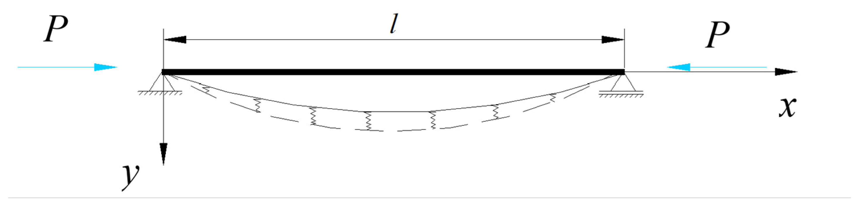
In the case of a beam supported by multiple equally spaced discrete elastic supports [
2,
3,
4,
5,
6,
7,
8], [
25], all having the same stiffness and subjected to an external compressive force P, the effect of these supports on the buckled beam can be replaced by the action of a continuous or discrete elastic foundation (
Figure 3 and
Figure 4).
The elastic response of the supports in a current section of the beam will be proportional to the displacement in that section. Denoting α as the elastic constant of each support and
d as the horizontal distance between two support points, the stiffness of the elastic supports can be expressed by the coefficient
β:
where
β represents the elastic modulus of the supports.
In other words, the value of
β above represents the magnitude of the support reaction per unit length when the displacement equals unity. Considering the coordinate system in
Figure 1, the deformed axis of the beam can be represented by the series:
The bending strain energy of the beam can be expressed as:
Expressing the strain energy of the elastic supports and considering that the reaction of an element
dx of the beam is
βydx, it can be written as:
The mechanical work performed by the compressive force
P is expressed as:
Expressing the equality between the mechanical work performed and the system’s energy, it can be written as:
so that the force
P will be:
Minimizing the expression (7) implies finding a relationship between the coefficients
a1, a2,
… an and leads to the critical value of the force
P. Considering all coefficients to be equal to 0 except for one, the deformed axis will take on a sinusoidal shape. Considering that this coefficient different from 0 is
am, it can be written as:
and the critical load will be given by the relationship below:
In the above relationship; m represents the number of sinusoidal half-waves into which the buckled beam can be divided; β provides information regarding the discrete elastic supports of the beam, while l, E, and I are intrinsic characteristics of the beam (the length, Young’s modulus, and bending moment of inertia respectively).
To determine the number of half-waves for which the aforementioned expression of critical loading attains its minimum, we initially consider the scenario where no elastic supports are present, hence setting m = 1. This scenario characterizes the buckling of a hinged beam. When 0 < β << 1, and m = 1 is considered in Equation (9), it is noticeable that under highly flexible elastic conditions, the beam can buckle without exhibiting intermediary points of inflection. Should β > 1, it results in a scenario where the force in Equation (9) is lower for m = 2 than for m = 1, causing the beam to buckle with two equal half-waves. The threshold value of β is derived from the condition that, at this critical value, the force P derived from Equation (9) should yield equivalent values for both m = 1 and m = 2.
By writing the same equation when the number of half-waves changes from
m to (
m + 1), we will obtain the limit value of
β for this case.
The relationship (9) that gives the value of the critical load
Pcr can also be written in the form:
where
L is defined as the reduced length. Values for the reduced length can be obtained based on tables where ratios of
L/
l have been established depending on values
β⋅l4/
16EI [
7].
3. Study on the Second Order Statics of a Compressed Beam on a Continuous Elastic Supports
In the case of open truss bridges (
Figure 2 and
Figure 3), in the transverse direction, the lateral displacement tendency of the compressed upper chord is counteracted solely by the transverse half-frames formed by cross-beams, verticals, and diagonals (
Figure 5).
Hence, for the analysis of the compressed chord, the simplified calculation model of a beam placed on an elastic support can be assumed.
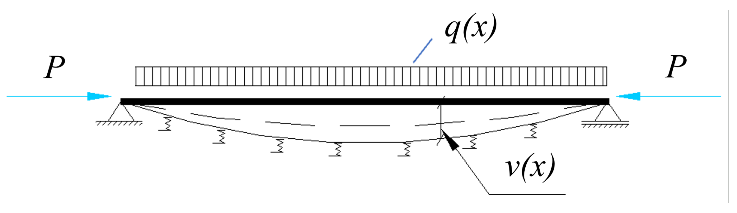
Let there be an elastic medium characterized by the following relationship:
representing the response of the medium to a unit displacement of a beam and having the dimension [FL−2], while pel [FL−1].
v is the vertical displacement of the beam (see
Figure 6).
On the other hand, it is known that in a deformed state, the relationships exist, with
q(
x) being the effective load on the beam (
Figure 6):
It is known that there exists a relationship between the bending moment and displacement:
By taking two more derivatives and assuming
EI = const., it is obtained:
Replacing (19) in (18) results in:
A principle verification of the relationship (20) is the following:
- -
If the response of the elastic medium does not exist, that is,
= 0 ⇒ 4
= 0 it leads to the following equation:
which corresponds to the second-order statics of the compressed beam.
- -
If
P = 0 ⇒
k = 0, it results in the following relationship:
which corresponds to the beam on an elastic medium.
To solve Equation (20), it must be taken into account that it is a second-order differential equation. The following notation is made: .
For the homogeneous equation, the characteristic equation takes the following form:
where Δ is the discriminant of the obtained quadratic equation. It results in:
Relation (24) can also be written as:
The solution of the differential equation will differ depending on whether the discriminant Δ is positive or negative.
3.1. Case 1
The discussion begins with the case where the discriminant is positive [
1,
2] (i.e., for small values of
λ and large values of
k).
The solution of the homogeneous equation is:
And incorporating
i into the constants, it can be written as:
for Equation (20) depends on the form of the function q(x), that is, on the load.
The integration constants are determined from the boundary conditions.
A verification of relationship (31) is the following:
If
λ = 0, from relationship (26) and (28), it results in
d = 1 and
α = k, while
β = 0; thus,
r3 =
r4 = 0, and the general form becomes:
namely, the homogeneous part of the equation of the deformed axis of the compressed beam in second-order statics.
3.2. Case 2
The discriminant Δ is, in this case, negative.
Thus:
where
d1 here is positive, meaning:
For the homogeneous equation, the solutions are:
Let us attempt a transformation of relationships (36) for the root
r1:
where retaining the positive part from the parenthesis results in:
For the second root
r2, it can be written as:
And retaining the positive part from the parenthesis results in:
For the third root
r3, it will be:
And proceeding in the same manner as with roots
r1 and
r2, it is obtained:
After retaining the positive part results in:
For the fourth root
r4, the calculation relationships are:
And applying the same calculation procedure yields:
After retaining the positive part finally results in:
So, for all the roots of the homogeneous Equation (23),
r1,
r2,
r3,
r4, the same form was obtained. Further notations are introduced:
Therefore, the solution of the homogeneous equation takes the following form:
An immediate verification of solution (57) is the following: when k = 0 (thus, there is no force P), it results in , and solution (57) exactly takes the form of the solution corresponding to beams on an elastic medium.
In studying the stability problem, one starts from the solution (57) of the homogeneous equation because it is observed that for common cases in practice, relationship (34) is fulfilled.
The characteristics of the beam and the elastic foundation are defined, as previously shown, by the quantities
. Three possible cases are distinguished (
Figure 7):
- (a)
The case of the beam with end supports resting on an elastic medium.
- (b)
The case of the beam without end supports and resting on an elastic medium—the case of non-conservative forces.
- (c)
The case of the beam without end supports and resting on an elastic medium—the case of conservative forces.
Case (a)—The boundary conditions that can be written are:
where
v represents the vertical displacement of the beam and
M represents the bending moment.
Taking into account the previously expressed variables
and the expressions (16), (17), and (56), the resulting system of homogeneous equations is as follows:
By solving the aforementioned system of Equation (59), i.e., by equating the determinant to zero, there is ultimately an arrival at a transcendental equation in k (that means, in P). This equation can be solved, for instance, through a stepwise graphical representation of the function D (here, being the determinant of the system of equations) for various values of k (or P). The first zero value for D will consequently lead to the desired solution.
Similarly, the other two cases corresponding to the beam without end supports and resting on an elastic medium (non-conservative forces—case (b), and conservative forces—case (c)) are solved in the same manner.
Case (b)—The boundary conditions for this case are:
These conditions lead to the following homogeneous system of linear equations:
Case (b)—The boundary conditions are:
Similarly to obtaining the system of Equation (61), the system of equations corresponding to this case is also derived, and it is presented below.
4. Validation of the Proposed Methodology Using a Case Study
Based on the theoretical considerations presented earlier, a case study was conducted to determine the critical buckling load for a beam placed on an elastic medium, which also has end supports. For illustration, the upper chord of a steel bridge structure with truss girders in use within the railway network of Romania was considered. The overall shape and dimensions are provided in
Figure 8. The same figure also depicts the cross-section of the considered compressed upper chord.
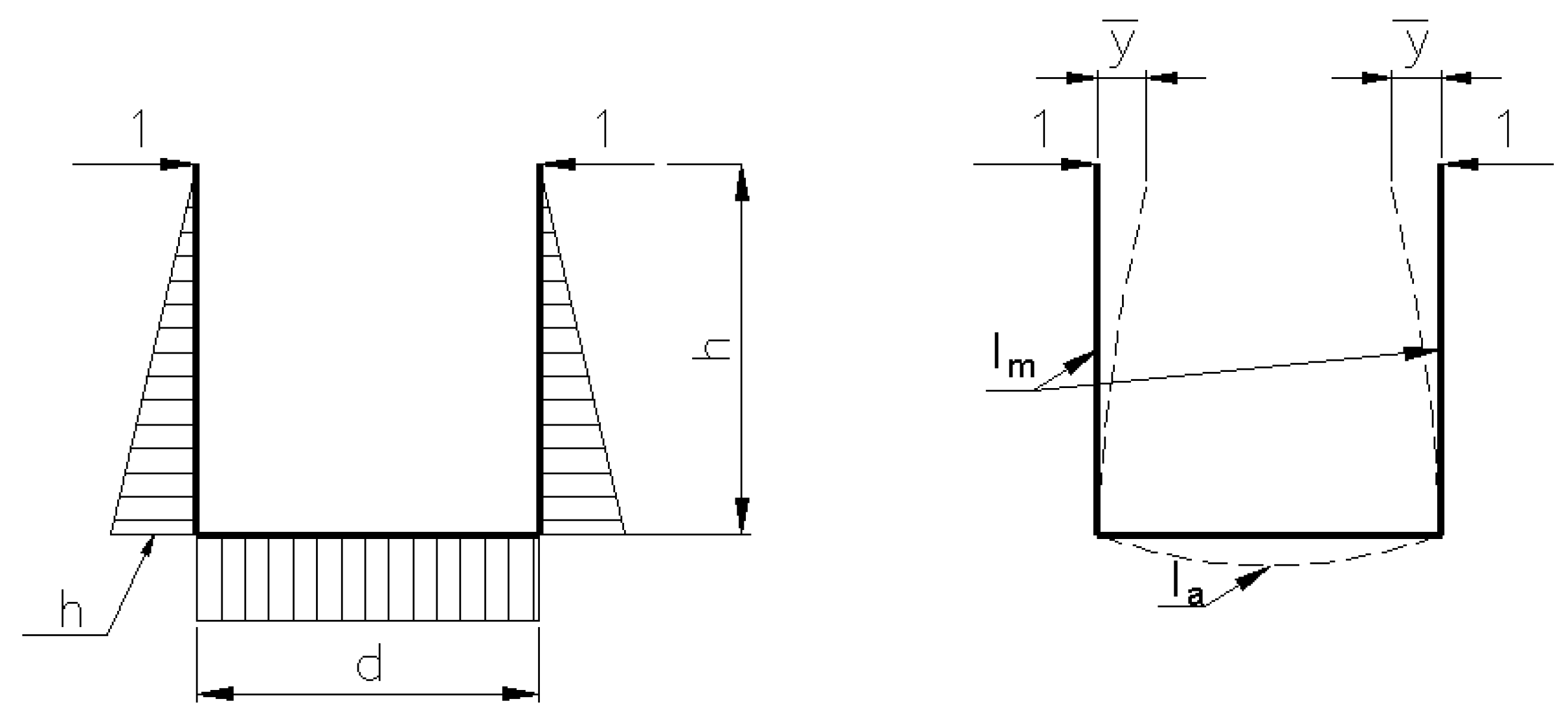
The analysis considered that the elastic supports of the upper chord are constituted by the transversal half-frames made of cross-beams and verticals (
Figure 9).
The unit reaction of the support (taking into account the geometric characteristics of the cross-sectional sections of the cross-beams and verticals) is:
The following parameters are involved in the above relationship:
h is the depth of the main girders, with a value of 8.47 m;
d represents the distance between the axes of the main girders (the theoretical length of the cross-beams), with a value of 5.10 m;
E is the Young’s modulus of steel (E = 2.1 × 10⁵ N/mm2);
Im is the moment of inertia of the cross-section of the verticals (about de strong axis), with the value of 37,588 × 10−8 m4;
Ia is the moment of inertia of the cross-section of the cross-beams (about the strong axis), with a value of 435,910 × 10−8 m4;
represents the transverse displacement of the upper chord caused by the application of unit force at the ends of the verticals.
The reaction per unit length of the elastic supports can be established, taking into account the distance between two consecutive elastic supports; therefore, the distance between frames (
dr = 5.5 m) is based on the relationship:
The moment of inertia of the cross-section of the upper chord was considered a weighted average of the moments of inertia of the segments composing the upper chord, as follows:
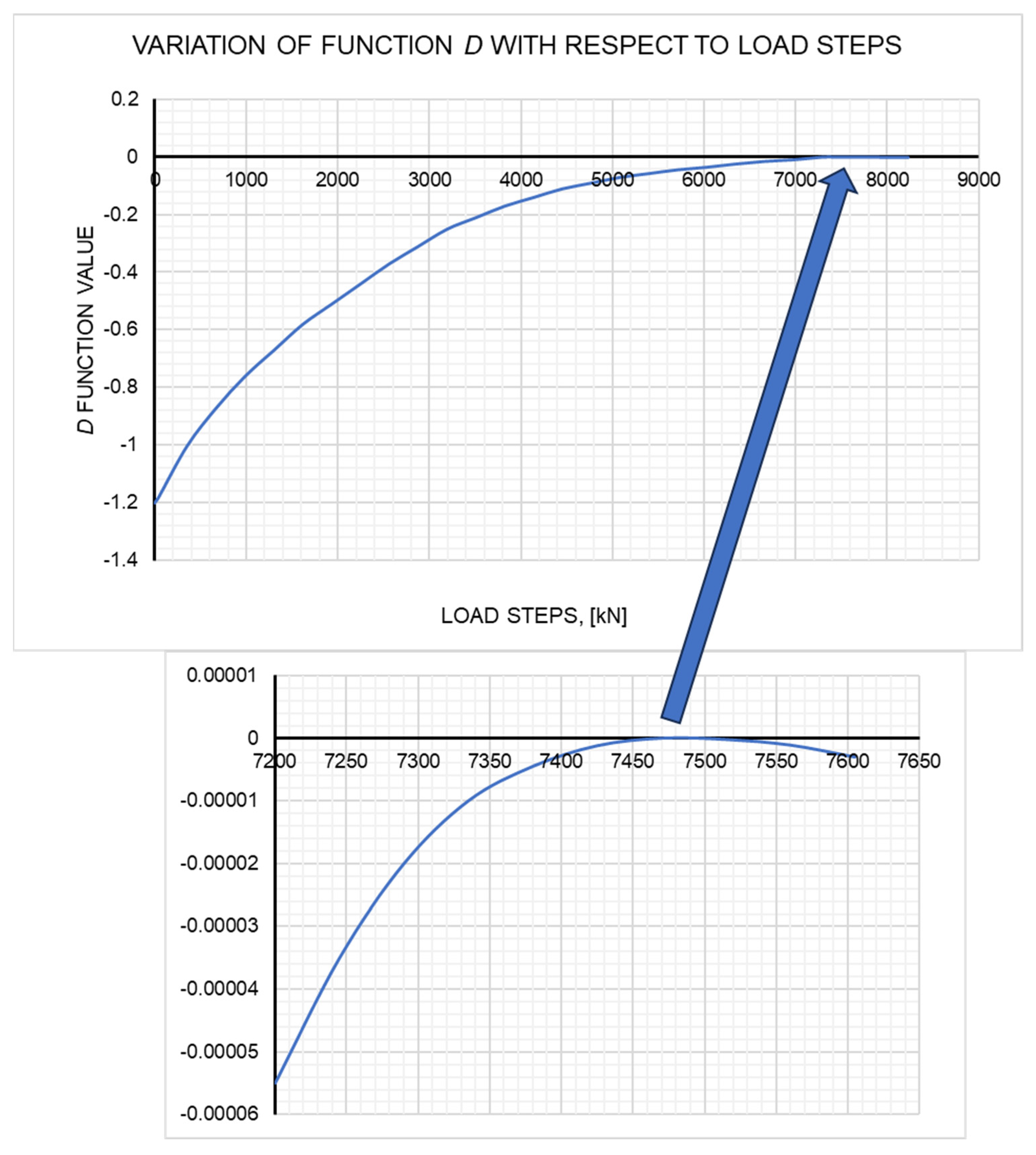
Considering the system of Equation (59), taking into account the quantities whose expressions have been previously presented, and using a number of load steps, a graphical representation of the determinant function
D of the system of Equation (59) was obtained, using a computer program created for this purpose, written in Borland Pascal. The abscissa value for which the determinant function equals zero represents the critical load value at which the beam on discrete elastic supports loses its stability. This value is
Pcr = 7470 kN. The
P-
D graph is shown in
Figure 10, where
D represents the value of the determinant of the system of Equation (59).
Starting right now from Equation (13) and considering the characteristics of the upper chord, an equation of the second order in m is obtained, which, when solved, provides the number of half-waves m of the beam at the moment of stability loss.
The second-order equation is:
and this leads to:
This value of
m introduced in Equation (9) leads to the following critical load value
Pcr:
A value even closer to the one obtained through the calculation using the created program is obtained based on the table values in Ref. [
7], which provide the value of the ratio
L/
l based on the ratio
. The value of this ratio for the considered case is 72.96, and linearly interpolating in the tables yields the value of the ratio
L/
l = 0.3784. Hence, the value of the reduced length is (based on the theoretical length of the beam)
L = 16.65 m. The critical force
Pcr in this case results in:
Another analysis was conducted using the finite element method on a three-dimensional model. Following eigenvalue buckling and geometric nonlinear analyses (large displacements), the critical buckling force value found was
Pcr = 7514.5 kN. For the analysis, the finite element system LUSAS [
26] was employed. The finite element model is shown in
Figure 11 in elevation and plan views.
In the modeling, non-conforming isoparametric Kirchhoff finite elements with four nodes, BS4, were employed [
26], where the fourth node was used to define the local coordinate plane. For this type of finite element, global displacements and rotations are independently interpolated using linear Lagrange shape functions for the nodes at the ends of the element and a quadratic function for the central node. This allows for the fulfillment of the continuity condition of displacements (
C0 class) in the element plane. It has been observed that considering a number of three to four finite elements for each structural element of the bridge ensures the stability and convergence of the solution process in nonlinear geometric analyses.
In all conducted analyses, the Total Lagrangian formulation was employed, along with the modified Newton–Raphson method, and as needed, the modified arc length method implemented by Crisfield [
26].
The convergence issues arising due to the presence of limit points (where the current stiffness parameter of the structure and the minimum pivot value in the stiffness matrix are negative) and bifurcation points (where the current stiffness parameter is positive, and the minimum pivot value in the stiffness matrix is negative) were resolved by manually constructing restart files in the programming language required by the software. Further, the iterative process was resumed from the point where it had previously stopped.
Using this methodology, complete force-displacement curves for the evolution of the displacement of the point located in the middle of the compressed upper chord of the bridge as a function of the loading factor (the value of the critical axial force in the chord) were plotted. Such a curve is presented in
Figure 12, below.
In this way, the value of the critical loading for the compressed upper chord was determined.
5. Discussion
The analysis conducted in this study aimed to determine the general lateral buckling critical load for the compressed upper chord of truss bridge decks using the model of a beam on continuous or discrete elastic supports. The proposed method differs from commonly used methods described in the specialized literature. These often focus on the deformation energy of the compressed beam on an elastic foundation, considering various axial force distributions along the bar.
Within the proposed method, the approach starts from the second-order analysis of a compressed beam on a continuous elastic medium, also considering a possible transverse action on the beam. By analyzing the material characteristics of the beam, cross-section geometric characteristics, and the stiffness of the continuous or discrete elastic supports, solutions to the differential equations describing the deformed axis of the compressed beam were obtained. These solutions were adapted for various end-supports of the beam, having as a result the formation of systems of linear homogeneous equations. To determine the critical load value, an alternative approach was proposed, plotting the determinant function of each equation system as a function of loading steps—a different approach compared to existing methods.
Using this methodology, a value of Pcr = 7470 kN was obtained, closely matching values derived from other methods in the literature. Employing the energy method and pre-determining the number of half-waves of the buckled beam resulted in a critical load value of Pcr,1 = 8495.2 kN. Another method used for comparison relied on the reduced length of the bar and existing tabulated values, yielding a value of Pcr,2 = 7509.7 kN.
Considering that the finite element method is currently a standard structural analysis procedure, the critical lateral buckling load for an existing truss bridge deck in Romania’s railway network was determined. Following an eigenvalue buckling analysis performed on a discrete three-dimensional model resulted in a critical load value of Pcr,3 = 7514.4 kN.
Furthermore, to highlight the capabilities of the proposed method, three bridge decks of old and new railway bridges in Romania were further analyzed, each featuring different dimensions and configurations of truss beams (
Figure 13,
Figure 14 and
Figure 15).
The results obtained from analyzing these steel decks using all the methods employed for Structure 1 were not detailed, as in the case of the first structure. Instead, they were condensed and presented in tabular form in
Table 1,
Table 2,
Table 3 and
Table 4.
As evident from the aforementioned values, the proposed methodology yields a critical buckling load value for the compressed beam on discrete elastic supports that aligns closely with values obtained through other existing methods in the literature. Moreover, the obtained value is the most conservative, indicating higher safety margins. This consistency in values suggests that the proposed method can effectively be used in stability analyses for compressed upper chords of half-through truss bridge decks.
The main advantages of this method lie in the potential for complete automation of the calculation process, a simple analysis model, and the use of a reduced set of well-defined parameters describing the calculation model, significantly reducing analysis time. This method could serve as an alternative to currently used methods like finite element analysis in confirming values obtained for complex structures.
Future studies will further extend this research to account for geometric and material imperfections resulting from construction processes, such as the heat treatment of steel, welding procedures, or eccentricities of applied compressive forces.
6. Conclusions
This paper presents a detailed analysis of determining the critical lateral buckling load for compressed upper chords of half-through truss bridge decks. The proposed method, involving discrete modeling of the beam on continuous or discrete elastic supports, offers a novel approach compared to traditional methods. It starts from the second-order statics of the compressed beam and employs an innovative strategy to determine the critical load. The detailed analysis of values obtained through various methods confirms the effectiveness and accuracy of the proposed method, suggesting that it could be a viable alternative to traditional methods used in structural stability analyses.


