1. Introduction
At present, with the development of technology and its application in various fields, including construction—one of the fastest-growing industries [
1]—it is worth paying attention to the concept of digital construction, which is a political initiative that contributes to solving the problem of low productivity and efficiency in the construction industry [
2]. The causes of problems in a construction project include unforeseen situations on the site, unfavorable climate for construction, inaccuracies in design and planning, lack of resources, etc. [
3]. To address the causes of these problems and issues of sustainability and stricter recycling and resource efficiency regulations at sites, groups of architects, engineers, builders, and facility managers are looking for ways to manage resources effectively [
4]. Digital building is the implementation of innovative approaches to integrate processes throughout the life cycle of a construction project using the concept of building information modeling (BIM).
Building Information Modeling (BIM) is the modern technology of digital transformation in architecture and engineering. The technology includes software and multi-disciplinary data processing procedures for designing, documentation and modeling [
5]. The key features of BIM are the modeling of data-integrated objects and enabled cloud platforms for collaboration purposes. The created models contain different data and can interact with other objects. The entire project will be full of information and dependent interactions, making it easy to make necessary updates fast and efficiently [
6]. BIM technology offers efficiency improvement in the construction industry in terms of increased collaboration between project participants [
7].
BIM technology can be utilized for different purposes in different engineering disciplines. One of the areas of significant interest for BIM is structural engineering analysis. The reasons for this interest are the ability of BIM software to have integrated material structural properties and to perform load condition analysis and geometry modeling. These three properties are the core required capabilities for structural engineering. In addition, BIM has the potential to add time and cost data to provide detailed information for construction purposes [
5]. This data can help to model multiple structural design alternatives to be compared by stakeholders [
5]. Several BIM tools are currently used in the structural engineering industry, including Autodesk Revit, Autodesk Robot Structural Analysis, and Tekla structures, which are the most-used tools in this sector.
BIM has become an innovative technology that created pressure on architectural firms. With proper implementation, companies that adopt new technology can have a big advantage in the construction industry. The proposed benefits are cost and time savings, significant reduction in design errors and conflicts and overall better quality of construction [
8]. It is stated that architectural firms in the US can take a big advantage in the market by using BIM, as it reduces costs and improves architectural practices. In his research, Gokuc found that Autodesk Revit software is the most popular BIM tool used among US architectural firms. The survey results indicate that among the top 500 American design firms, 99% have Revit software and use it for architectural design purposes [
8]. For designers and architects, BIM has become an effective tool, so BIM implementation is gradually developing in this discipline.
While other engineering disciplines have progressed in implementing BIM technology principles, it seems as though the geotechnical engineering position is being ignored. Vaniek et al. stated in 2021 that the primary reason for this is the risks associated with the geotechnical parameters of the soil [
9]. Ground soil properties change with position, which creates some uncertainties. Most of the geotechnical firms in the US still use the traditional 2D process and software to create foundation designs [
10].
BIM, as with any other engineering branch, has benefits in incorporating information into geotechnical projects. The main role of BIM in geotechnical design is to minimize the risks and optimize the foundation construction phases [
11]. Building Information Modeling technology has significant potential for geotechnical engineering purposes, as it reduces costs by reducing the risk of foundation.
In the construction industry, BIM is a common concept known as a powerful method to optimize the construction process in terms of money and time. For example, in the UK, by 2014, 54% of all projects were made using BIM technology [
10]. The main aspect of digital construction is the creation and reuse of consistent digital information by project participants throughout the construction and operation of the facility [
2].
The construction industry consists of two main parts: Structural Engineering (SE) and Geotechnical Engineering (GE). It so happens that much of the BIM research and the BIM methodologies developed are for the SE area. This could be attributed to the fact that it is easier and simpler to develop new 3D modeling techniques for implementation in SE rather than in GE. In addition, many BIM-specific SE standards have been developed and maintained by researchers, industry experts, and the BuildingSMART organization [
12].
As to whether such standards exist for civil engineering, the German research project ForBAU, for example, has come up with several concepts for creating parametric 3D models of bridges and roads. On the other hand, a Japanese research team has developed a new concept defining a product model for shield tunnel projects. Moreover, similar projects have been launched in countries like Korea, France, Finland, and the USA. These infrastructure projects aim to find various solutions that implement a standardized building infrastructure information model [
12].
An important part of infrastructure construction is geotechnical design, which is complex and diverse. Geotechnical engineering is closely related to other disciplines, especially geological and structural engineering. During the construction process, there are often moments when interdisciplinary coordination is needed, which is one of the project management tasks. Throughout the process, various types of data must be provided to geotechnical engineering in time, and this requires fast processing and integration, real-time feedback, and construction guidance.
Currently, there are various approaches for integrating BIM technology in the field of SE. However, several studies are needed to reach a similar level in the field of civil engineering (CE). Today, most geotechnical and infrastructure work is carried out in a traditional 2D-based manner, allowing engineers to focus on a particular task. But when there are adjustments, each engineer must redesign their part, which subsequently leads to less efficient, less consistent, and laborious execution of the task.
The second problem is the lack of interaction between participants from different disciplines. In many cases, each organization designs its part separately, and there is no data transfer to other design areas. Therefore, if it is necessary to exchange information, engineers are faced with reconstructing the system, which requires a certain interpretation of geometric and semantic information [
13].
While BIM technologies are used to plan and manage the construction process from the beginning of a project to operation, the model is devoid of a geotechnical aspect, which is fraught with costly errors, particularly if the project is based on infrastructure [
14]. Because many projects designed using BIM do not consider soil data, there is a significant possibility that integrating geotechnical data into the BIM process will help optimize construction [
10]. The main challenge in using geotechnical data for the BIM team is extracting and assimilating this data from archived geotechnical data, which are mostly geotechnical survey reports and geological sections. In addition, there is no convenient link between the original data and those generated by construction to correct interpretable errors in the geotechnical data, while no way has been found to combine monitoring data with the original geotechnical data to determine the trend of monitoring variables [
14]. Therefore, this work aims to identify and evaluate various integration strategies and methods of integrating geotechnical data into the BIM process and evaluating them. In this research work, a qualitative research method was applied, and a literature review was done on the topics of geotechnical engineering, building information modeling, and integrating geotechnical information into digital building modeling. This paper also considered and described case studies during which various strategies for introducing soil information into the modeling process were applied.
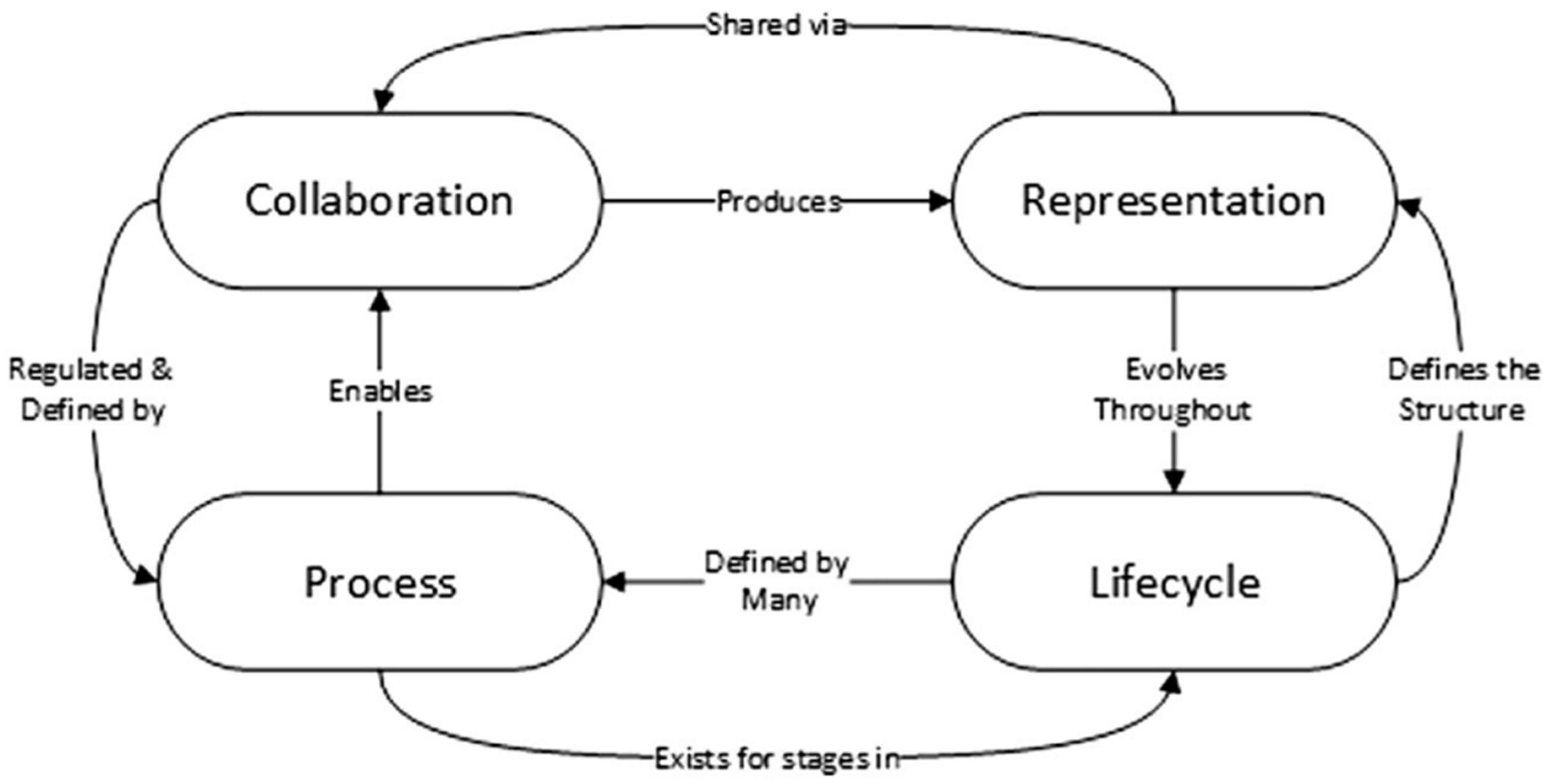
4. Perspectives of BIM Technologies in Geotechnical Engineering
The geotechnical digital twin helps to study and analyze the entire site using a single model that interacts with other models in the BIM platform, extracting soil properties and field reports, providing profile sections, measuring volumes, and modeling thematic maps. In addition, there are various other advantages to geotechnical design [
32].
Figure 2 shows the common geotechnical components of BIM.
Tawelian and Mickovski [
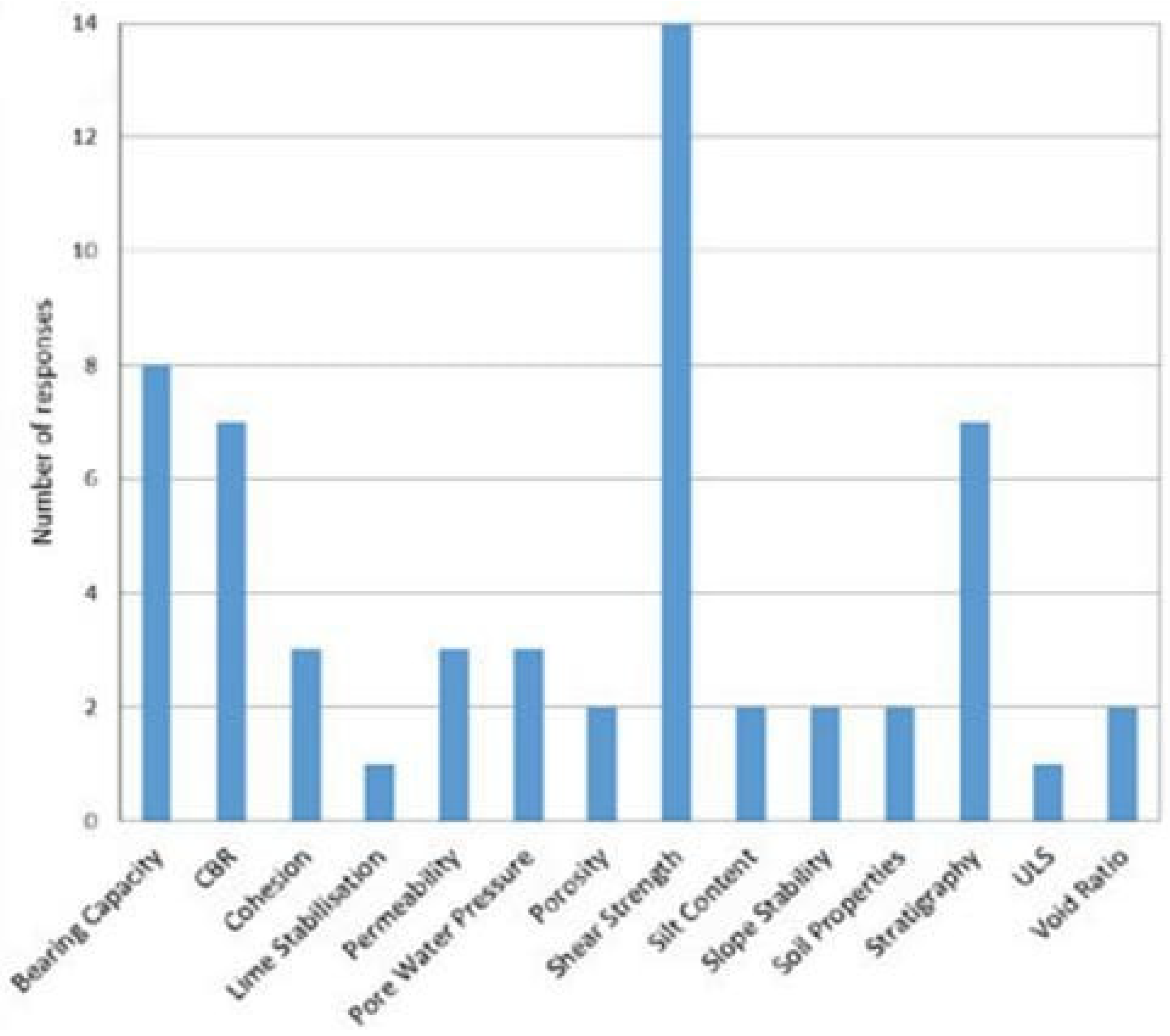
10] examined the current attitude of UK geotechnologists towards the possibility of using geotechnical data in BIM and to find out if there was a need for geotechnical design data that would improve engineering design using BIM. To this end, a quantitative analysis of the survey among qualified engineers was carried out, as well as the analysis of geotechnical infrastructure and construction of a case study to explore the attitudes of the parties involved regarding the application of the BIM approach.
The interviewees noted several categories of data that need to be integrated into the BIM process. The main three categories are:
- -
Parameters of soil strength (37%);
- -
Characteristics of the bearing capacity of the soil (33%); and
- -
All data categories in the survey can be locally very heterogeneous, and detailed study and interpretation are necessary to obtain characteristic values [
10].
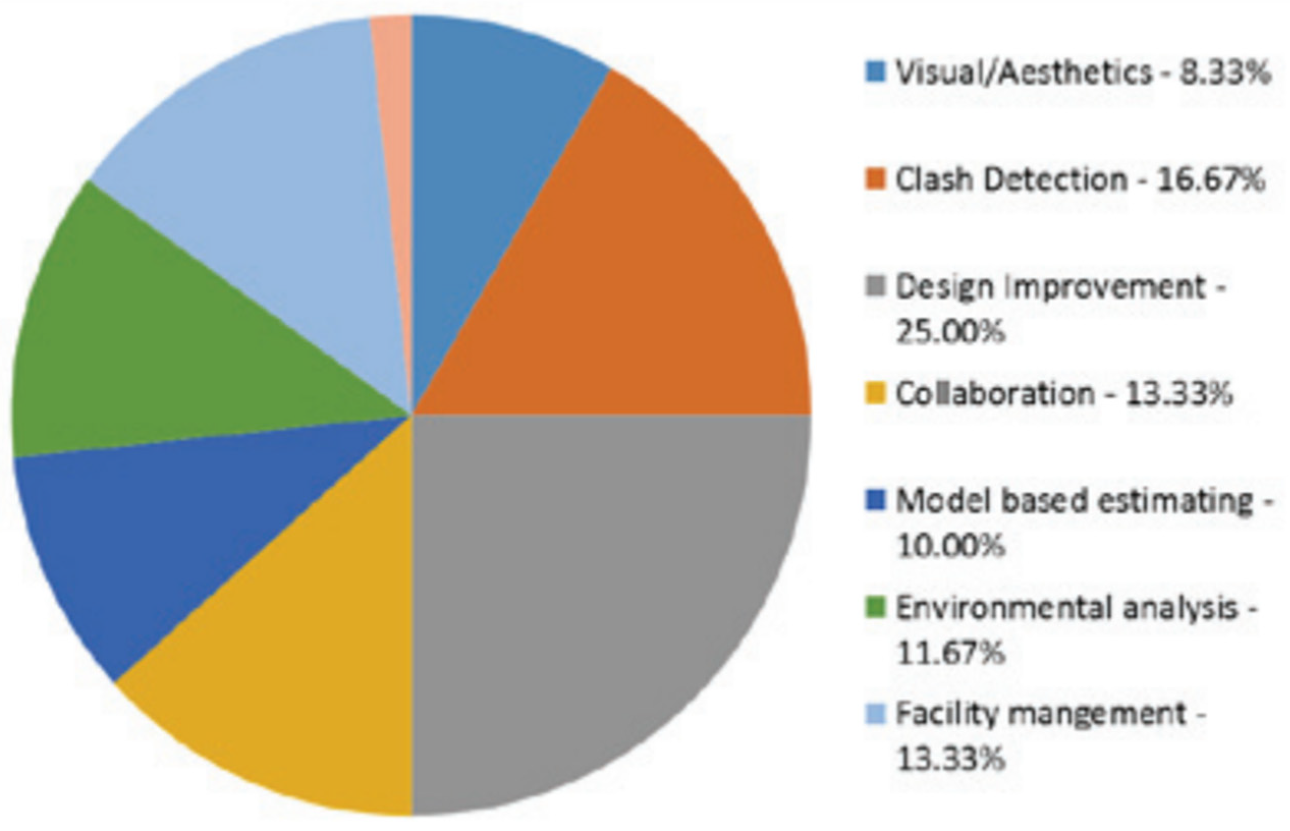
According to the answers of those who passed the survey, the key factors determining the effectiveness of working with BIM technologies are:
- -
Design improvement (25%);
- -
Clash detection (17%); and
- -
Collaboration (13%).
It was found that support for modeling/assessment or analysis with it was low (12%) (
Figure 4) [
5].
There is consistency between the results of the survey and the published data, which describe the positive aspects of working with BIM, such as minimizing time and costs by streamlining the process and collaborating with specialists from different disciplines in the same workspace [
33,
34].
Berdigylyjov and Popa [
11] also investigated the advantages of geotechnical BIM, noting the fact of optimizing virtual design and minimizing risks. Since the soil is notable for its heterogeneity and differences at different locations, BIM technologies are the optimal solution as a tool for the geotechnical team. In addition, specialists having geotechnical data, such as geological forecasts and groundwater conditions, can use them to determine the suitability of the soil for reuse.
The importance of working with geotechnical information in the BIM platform is in implementation and obtaining data. With the help of site models with data, including mapping and remote sensing, geotechnical engineers can assess a detailed picture of the project, thus improving the stages of soil investigation at the site [
32].
The previous study [
29] noted that integrating geological and geotechnical data into BIM modeling increases the opportunity for quality improvement and the convenience of the model in many stages of construction, including design, construction process, and infrastructure lifecycle management.
Considering the great demand for integrating and sharing volumetric data in geotechnical engineering, which is growing over time, it is predicted that the BIM approach will realize a common systematization of software in the geotechnical engineering sector. However, a significant challenge along the way is that the data standard is not unified between geological and BIM models, so consensus needs to be reached [
19].
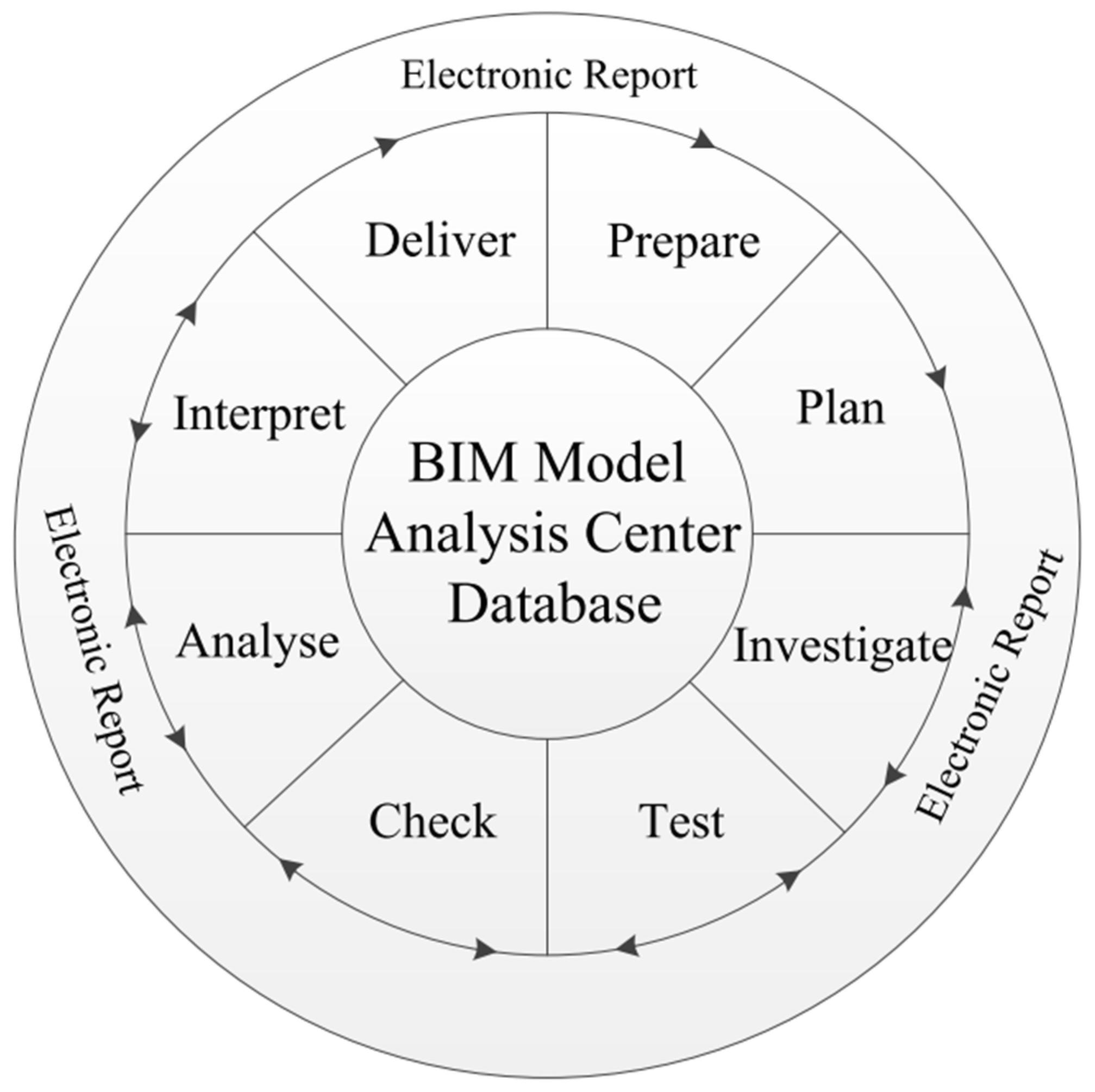
One of the possible operating modes for performing BIM-based geotechnical operations is DMA. Expanding this abbreviation, D is the database where the geotechnical information necessary for management and organization is collected. M stands for 3D digital geotechnical model, which aims to achieve a three-dimensional spatial distribution and representation of the topological relationships of the object. A is an analytical center that analyzes the provided geotechnical information, consults, and makes decisions. The DMA mode is different because as soon as geotechnical information is created, it will be integrated into a comprehensive analytical center. This center checks these data for validity, processed and analyzed simultaneously. Therefore, the possibility of data loss, which usually occurs between stages, is eliminated [
35].
Figure 5 provides a diagram of this mode.
The interpreted result directly depends on the accuracy of the geotechnical information. This accuracy can be determined by various factors, among which are the geotechnical specialist’s experience, the tool’s accuracy, and the process of transferring data between stages [
35].
In the previously described mode, the accuracy of the interpreted result is controlled in the following ways. First, all data operations occur on the same database to eliminate data loss in the process. When project participants use the data from this database to create a digital model, statistics transformation tools will be applied. The data could follow a normal distribution to global model trends and remove anisotropy. With the help of visual interpretation in 3D, some errors in spatial geotechnical data can be identified. An example is creating a 3D model of a well where the maximum elevation should match the surface elevation in the same place. If a significant difference occurs, a writing error may be possible [
35].
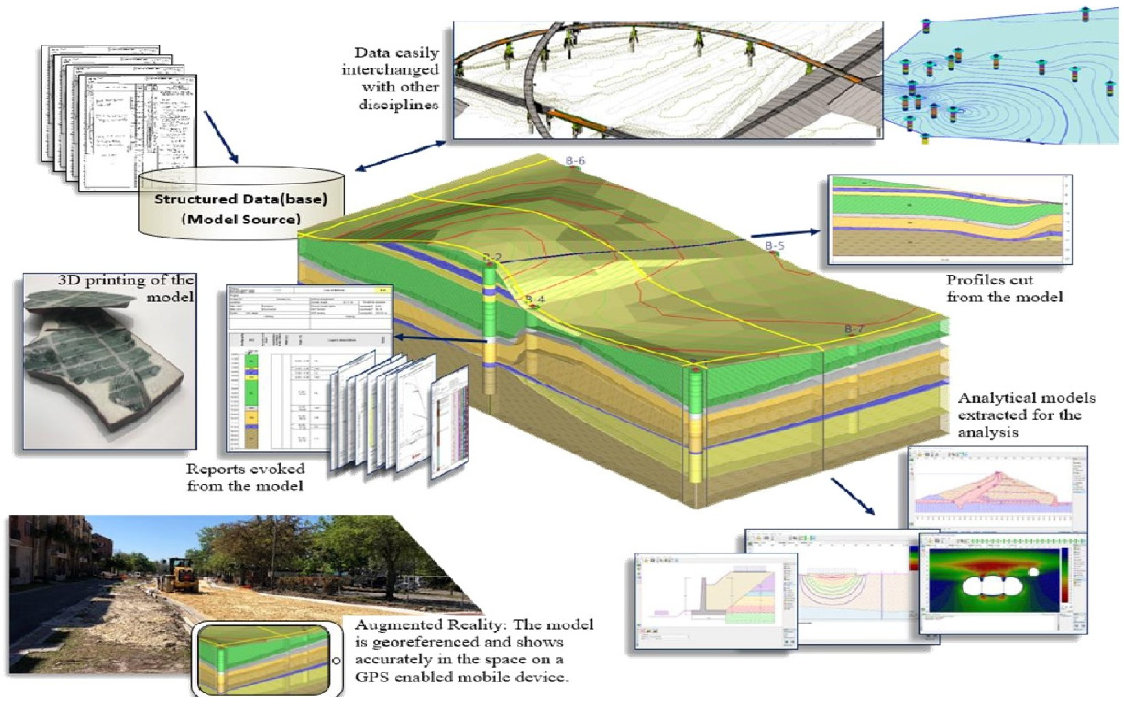
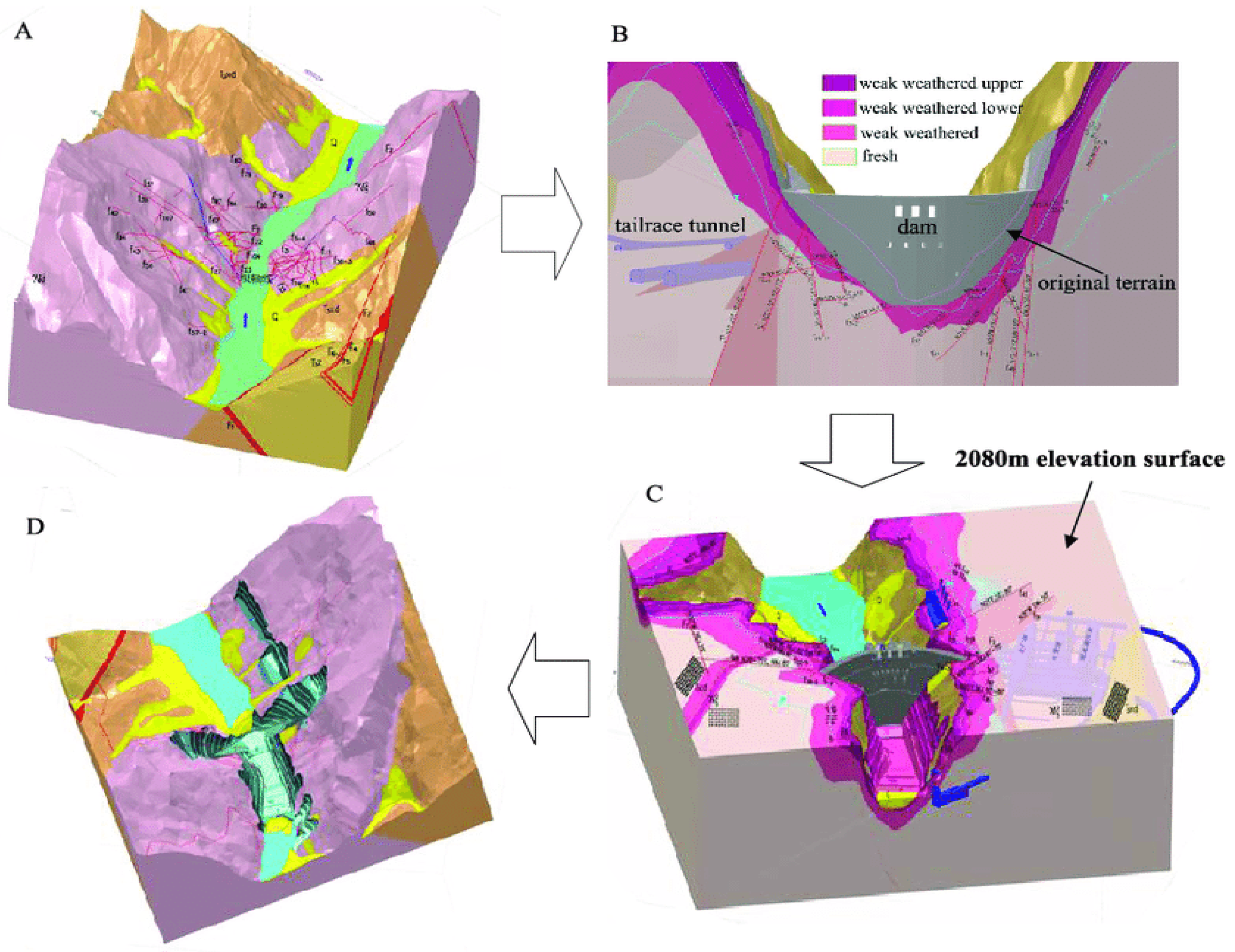
Geological analysis can be done in 3D space, providing an information base and a digital model (
Figure 6A). In addition, this analysis contains sectional views from different perspectives and excavation in different ways, as in
Figure 6B.
Figure 6C shows a diagram of a horizontal section at elevation—2080 m in the area of contiguity for geotechnical engineers.
Figure 6D shows the layout of the virtual excavation of the dam, the lithology that was determined during the excavation, and the amount of excavation that can be easily calculated to ensure accuracy in budget allocation as well as in construction [
14].
Logging into several different software daily to access BIM information is common for many project teams. However, because the information in these applications can be disparate, it can be difficult for project teams to make informed decisions, collaborate, and share information.
In many cases, design and engineering organizations use a combination of well-known software applications that are most appropriate for a given task. However, since design teams often use various other software tools to manage construction, fields, and control documentation, model collaboration can be disconnected from additional downstream information. In such cases, standards can help solve this problem. With open standards for information sharing, project teams can use the software they prefer while allowing teams to share information [
19].
There is a way to manage geotechnical data in BIM modeling, which was proposed by Wu and others in 2021 [
19], where they proposed to use an extended version of the IFC for data integration and exchange.
Using BIM technologies, it became possible to exchange various types of information about construction projects using the international Industry Foundation Classes (IFC) open data standard, which is currently considered the most extensive database since it was published [
31]. Furthermore, the IFS is distinguished by its scalability, which allows it to be an intermediary in implementing cross-special, cross-domain, cross-stage, and cross-platform interaction and data exchange [
32].
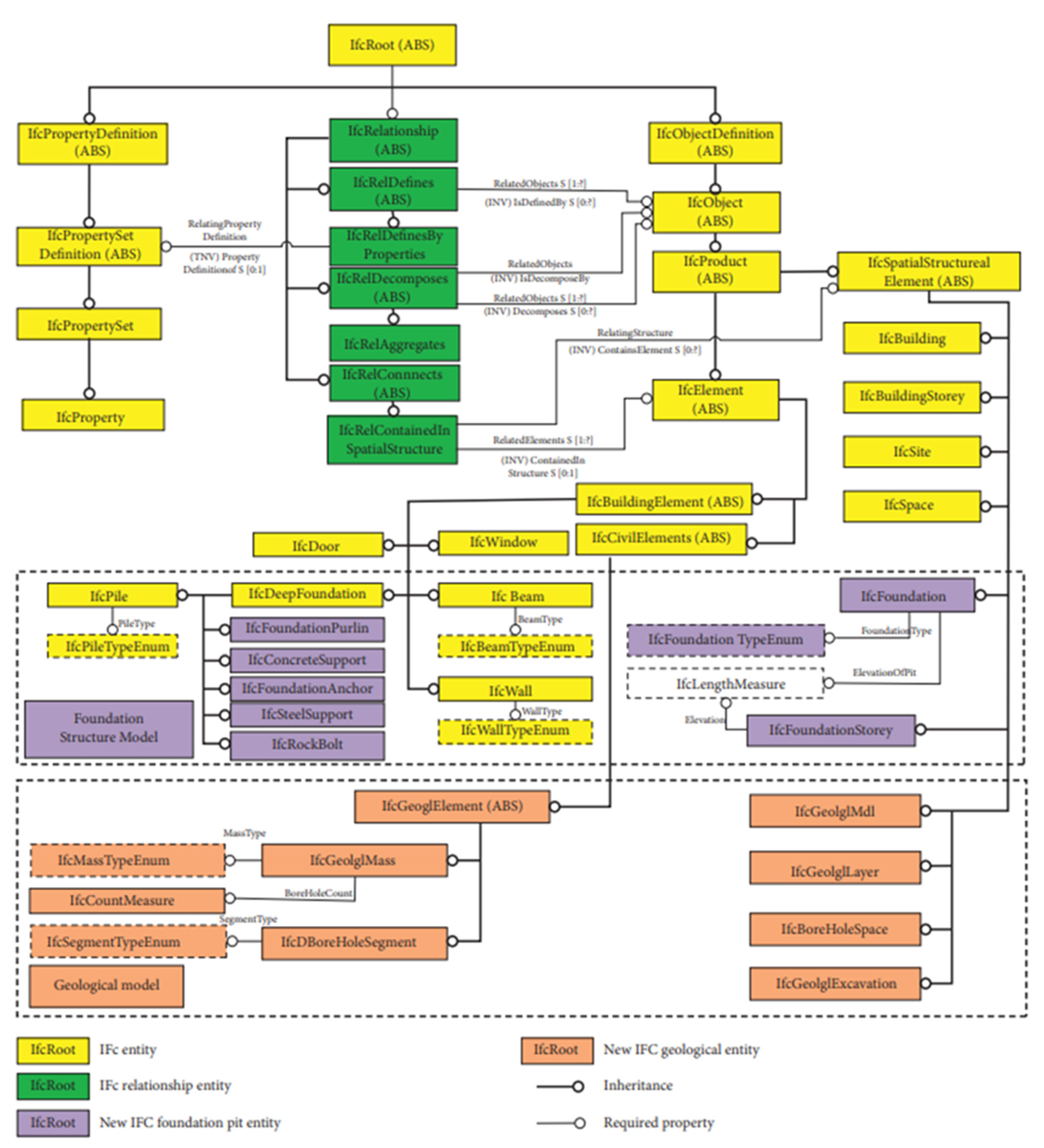
To generate information about the geotechnical structure in the BIM domain, the corresponding components in terms of entity and relationship were created using the integral components in the IFC classes. This method has been called “built-in generation schema,” which has not previously been considered as an integration tool for geological data within IFC.
However, since already-existing objects do not contain all the necessary geotechnical data, a “plug-in extension scheme” has been proposed that creates new objects and defines their characteristics and relationships. Thus, the result of the work [
34] is an integrated BIM model with geological and geotechnical data formulated based on the IFC. Creating such a model removes obstacles, such as the lack of a common data standard between the geological and structural models.
The main concept in the IFC can be called an entity—a class of objects with common properties, which is created in an object-oriented way, giving information by defining attributes and adding constrictions to them. The structure of the IFC consists of a characteristic hierarchy and a modular characteristic, the data schema of which can be considered at four levels. These are the following levels: Domain, Interoperability, Core, and Resource.
At the core level, to ensure the model’s sustainability and facilitate updating the entity, there is a core schema and a schema for the core extension. The IFC standard can offer three different extension mechanisms: entity definition based on IfsProxy, entity extension, and extended property set [
33].
The most important entity at the core level also considered the root entity, is IfsRoot, which implements the remaining entities at the domain, interoperability, and core levels.
Figure 7 shows the three main subclasses of IfsRoot—IfcPropertyDefinition, IfcObjectDefinition, and IfcRelationship.
Speaking of IfcObjectDefinition, this is often a definition of IFC objects which is further derived from it as an object entity definer within the IFC standard [
35]. A subtype derived from IfcObject, IfcProduct, provides objective or material entities that participate in the building process. From it comes the components of the project object—the physical entity IfcElelement and the entity of the spatial structure IfcSpatialStructurElement. IfcRelationship defines relationships between objects from IfcObject using its subtypes and integrates new entities that have been added into the IFS framework. The third subclass of IfcRoot, IfcPropertyDefinition, which can be defined as a property definition entity, contains the properties of a specific object. A property set is defined by an IfcPropertySetDefintion that derives from IfcPropertyDefinition. Geotechnical characteristics and requirements of the model must be considered for the extension of the geotechnical data, which consists of the IFC standards. A derived subtype of IfcObject is chosen as a supertype for a particular object in geotechnical engineering, and then properties are assigned to it. From the IfcRelationship, the appropriate subtype is associated, and the related entity property is defined. With the help of IfcPropertySet, the dynamic properties of an entity are extended, and the specific requirements of a construction project are satisfied.
Since the characteristics of engineering-geological structures coincide with general structures, the outline of the thing from the primary can inherit and ask the thing of the other, which is already within the IFS data schema. The IfcBuildingElement in an IFS structure defines and represents some of the common elements in the building area. An abstract entity is created in IfcBuildingElement, which means the physical object of the geotechnical structure extends the objects in it. Some elements in the new subtype may call entities already in the system, and some will need a new definition and description. Approximately it represents the “Built-In Generation Schema”.
At present, the IFS structure is, for the most part, suitable only for building structures, and since the three-dimensional geological model data and the identified BIM structure data are markedly different, there are obstacles to integrating geological data into the IFS structure. It is necessary to create the latest objects with new relationship characteristics and, therefore, extend the latest data types. Given that IfcCivilElement was added in IFC4 for an outline of entities of engineering objects, IfcGeolglElement is often integrated directly into IfcCivilElement so that the geological model is often expressed.
All IfcGeolglElement elements must be re-integrated. Therefore, some researchers created a geological model and proposed a plug-in extension scheme [
19]. A conventional digital three-dimensional geological model contains geological features such as formations, faults, underground cavities, etc. In their work, these objects belong to a class of objects, which together are called the geological mass, and real objects can be distinguished by their types.
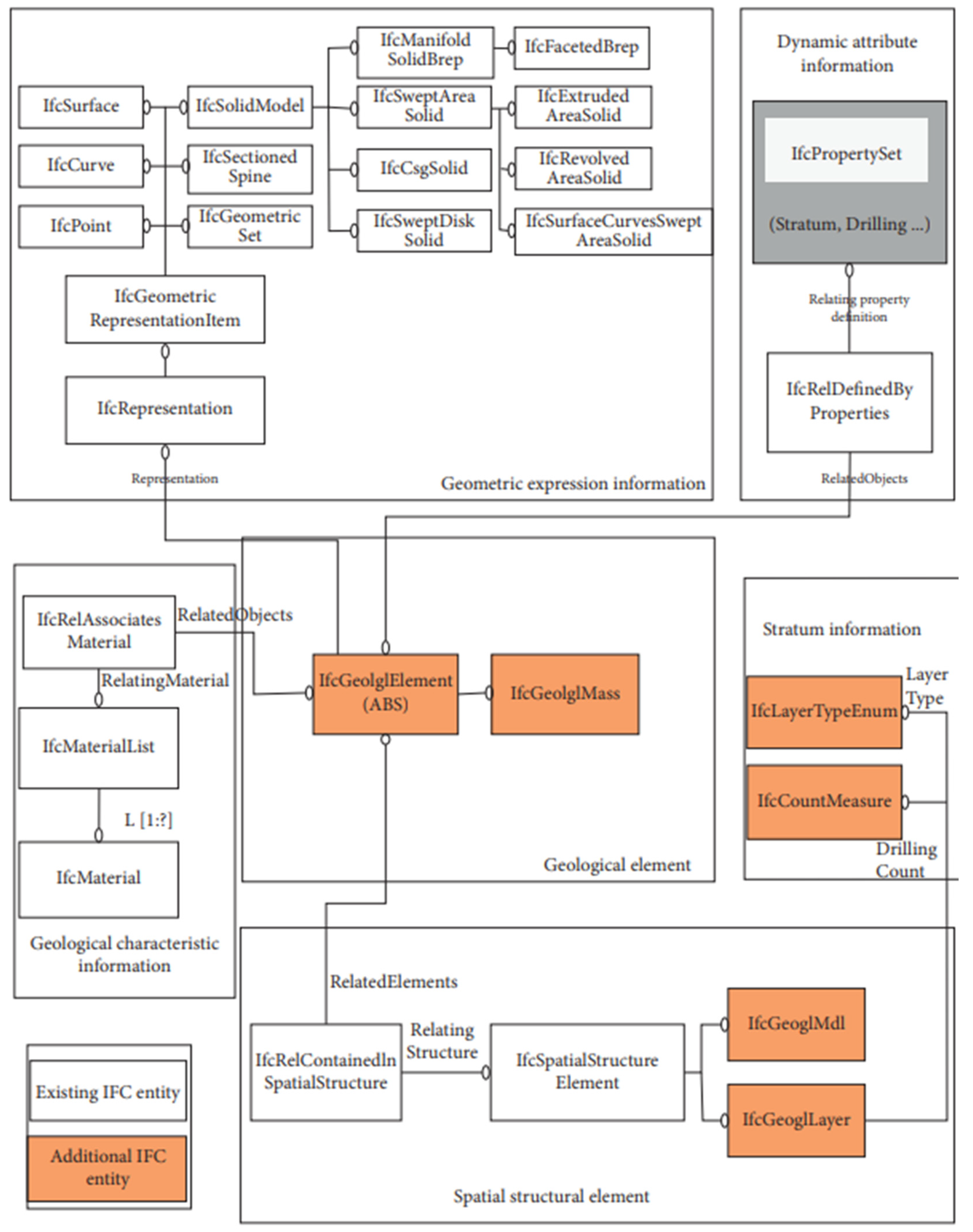
The creation of a geological model is aimed at determining the components of the IFC of these geological objects, their relationships, and data on their characteristics. The new integrated geological components of the model contain elements of the geological spatial structure and geophysical elements. IfcRelContainedInSpatialStructure provides the relationship between geophysical elements and geological spatial structure elements, and the relationship between geological spatial structure elements is provided by IfcRelAggregate. Soil layer and rock properties, physical, mechanical, and chemical characteristics, and other data of the new embedded object are implemented using the IfcProperty extension and the IfcPropertySet property set. Its general structure is shown in
Figure 8.
The integration of geological and geotechnical data using the IFC considers a variety of foundation design models and offers a “library of foundation design models” to store various basic elements [
19]. Using parametric modeling, they apply a new approach to the modeling process based on BIM technology in their work. In addition, the IFC extension for the geological model was applied for a one-to-one mapping between the geological model and, therefore, the IFC model. This extension allowed the output of the geological information model to support the extended IFC standard. Finally, based on the above data generation method using IFC, geological models and geotechnical structure models were integrated, thus eliminating the problem of inconsistency with existing data standards. This model combines geotechnical characteristics and can also create numerical grids for geotechnical calculations.
For the successful application of geotechnical data in BIM modeling, one must overcome the difficulty in the form of a lack of a convenient method for introducing geotechnical data from special geotechnical software into BIM technology. The strategy proposed by Fabozzi et al. [
29] and other researchers describes a method in which geotechnical data can be provided not only visually but also contain information about the characteristics and properties of the soil, thereby determining the impact of these qualities on the construction process and the further operation of the building structures.
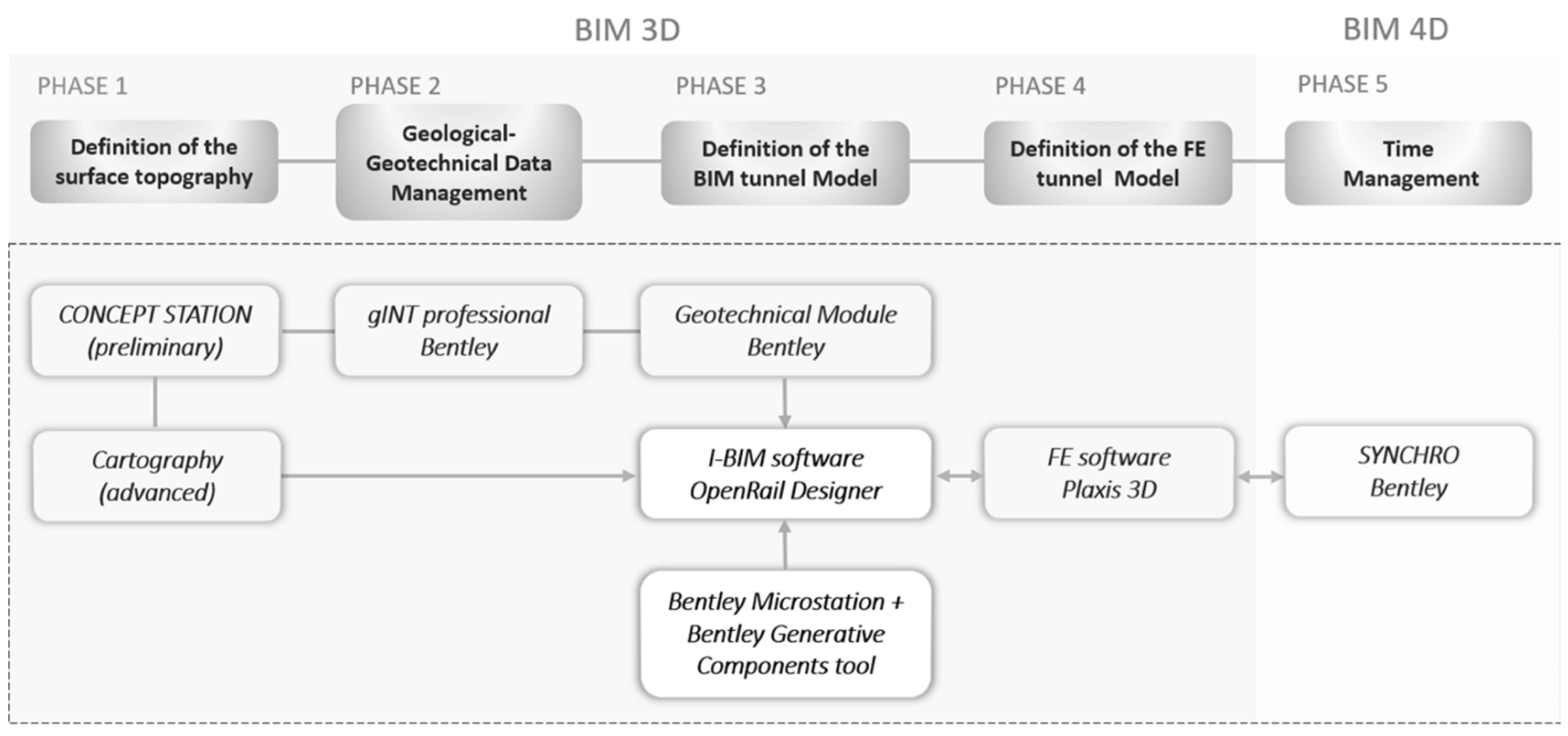
The paper by Fabozzi and some researchers offer a new alternative perspective on BIM exploration and experimentation by offering a 3D model in which the geological and geotechnical data defining the terrain, tunnel structure, and excavation process can be found [
29]. To achieve this goal, the following Bentley software 2021 package was used:
OpenRail Designer 2021 R 1 (version 10.10.21.04) —to model the structure of the tunnel along its trajectory;
gINT Professional 2021—to import the model of the surrounding soil for further use of the soil data in the study;
SynchroPro 2021—to add time as a fourth dimension of the model to link to the construction process.
BIM-to-FEM-to-BIM interoperability with Plaxis 3D finite element geotechnical software was used to assess how the excavation would affect the elevated urban area.
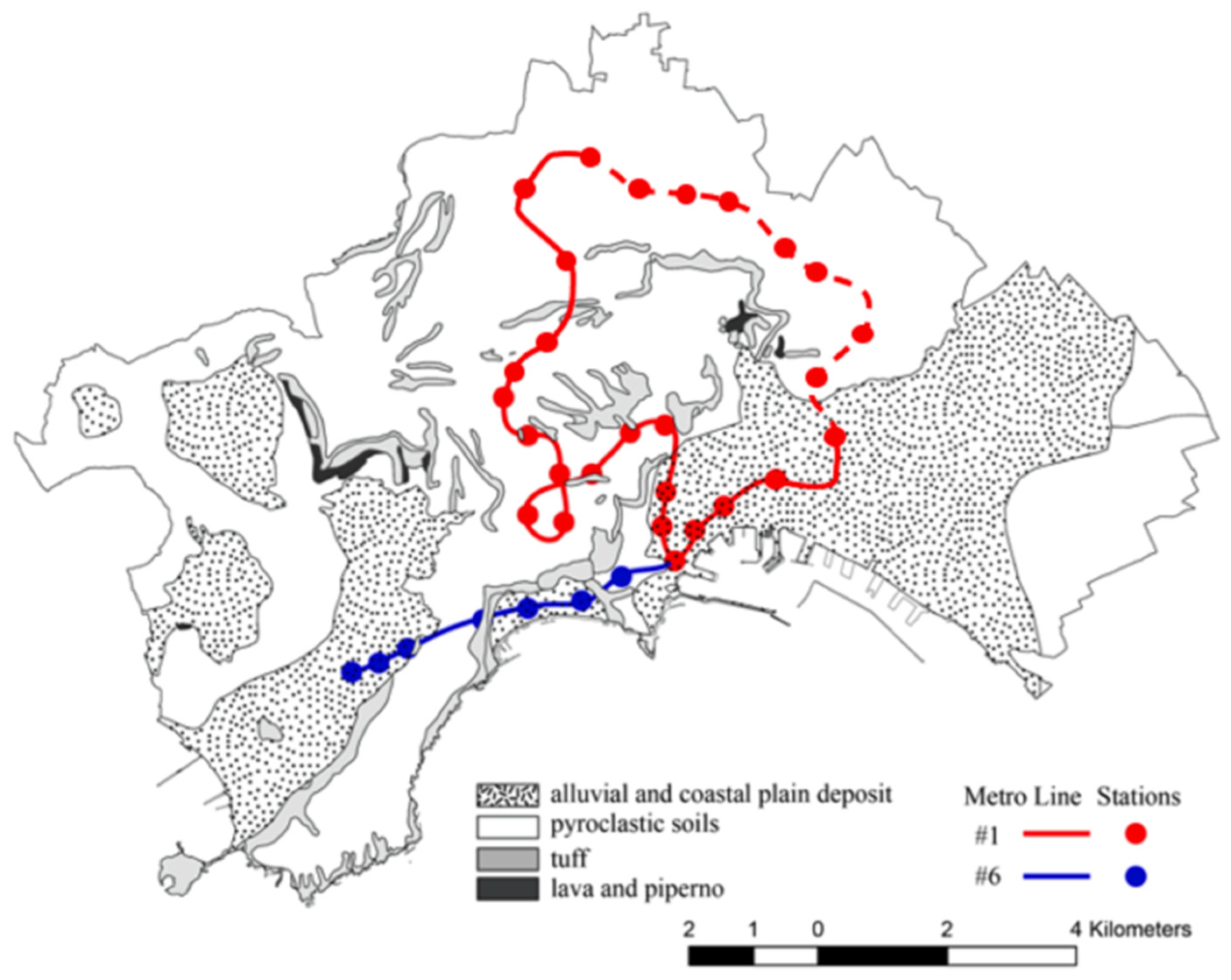
The case study carried out in this work took place over the Naples metro of two main lines that are still under construction. As shown in
Figure 9, line 1 is marked with red and line 6 with blue lines.
According to the plan, part of the tunnel along the line that is being built will be modeled for practice in a BIM-based project. The construction process of the tunnel consists of five stages. The first stage can be described as the installation of an umbrella arch of a conical cone to have a pre-arch effect, with which a preliminary restriction appears around the cavity. To strengthen the front side, fiberglass pipes are being built in. In the second stage, steel ribs are placed at a distance of 1 m along the axis of the tunnel, and shotcrete with a thickness of 0.2 m is added where the cavity was excavated. In addition, at the same second stage, an abutment is poured on both sides of the tunnel section. After these procedures, the upper part is poured, and in the following steps, the inverter and the bench are installed [
29].
The workflow can be described in five major steps, which are named and provided visually in
Figure 10.
In the preliminary design, a DEM was used to define the topographic surface. In the advanced design, mapping data from a specific intended area was used. The second phase manages geotechnical and geological data from the site investigation, including GIS-integrated logs and reports. gINT Professional was modified to manage geotechnical and geological data. In phase 3 of the BIM workflow, OpenRail Designer imported geoscience functional software soil data to define soil stratigraphy using the geotechnical tool. After establishing the digital three-dimensional landscape model in the third phase, the BIM tunnel is eventually modeled utilizing the tunnel lining structure and 3D tunnel alignment. OpenRail Designer was used for the tunnel’s main section, while Bentley MicroStation’s Bentley Generative Components tool parametrically constructed the steel tube arch along a generic cross-section. The fourth phase tests the urban area’s surface after excavation. A numerical finite element model of part of the research area is created by importing the soil layer and tunnel geometry into Plaxis 3D.
Bentley’s 4D BIM measuring program Synchro adds construction time in phase five. The synchronization of BIM, timetable, and field conditions enables visibility into design data and design, allowing fast and easy information exchange and control over project modifications [
29]. BIM integration into geotechnical works has been slower than predicted due to soil variability and modeling challenges. Few geotechnical articles apply BIM. An alternative form of the hill near Sant’Agata de Goti, southern Italy, nails the ground to support it [
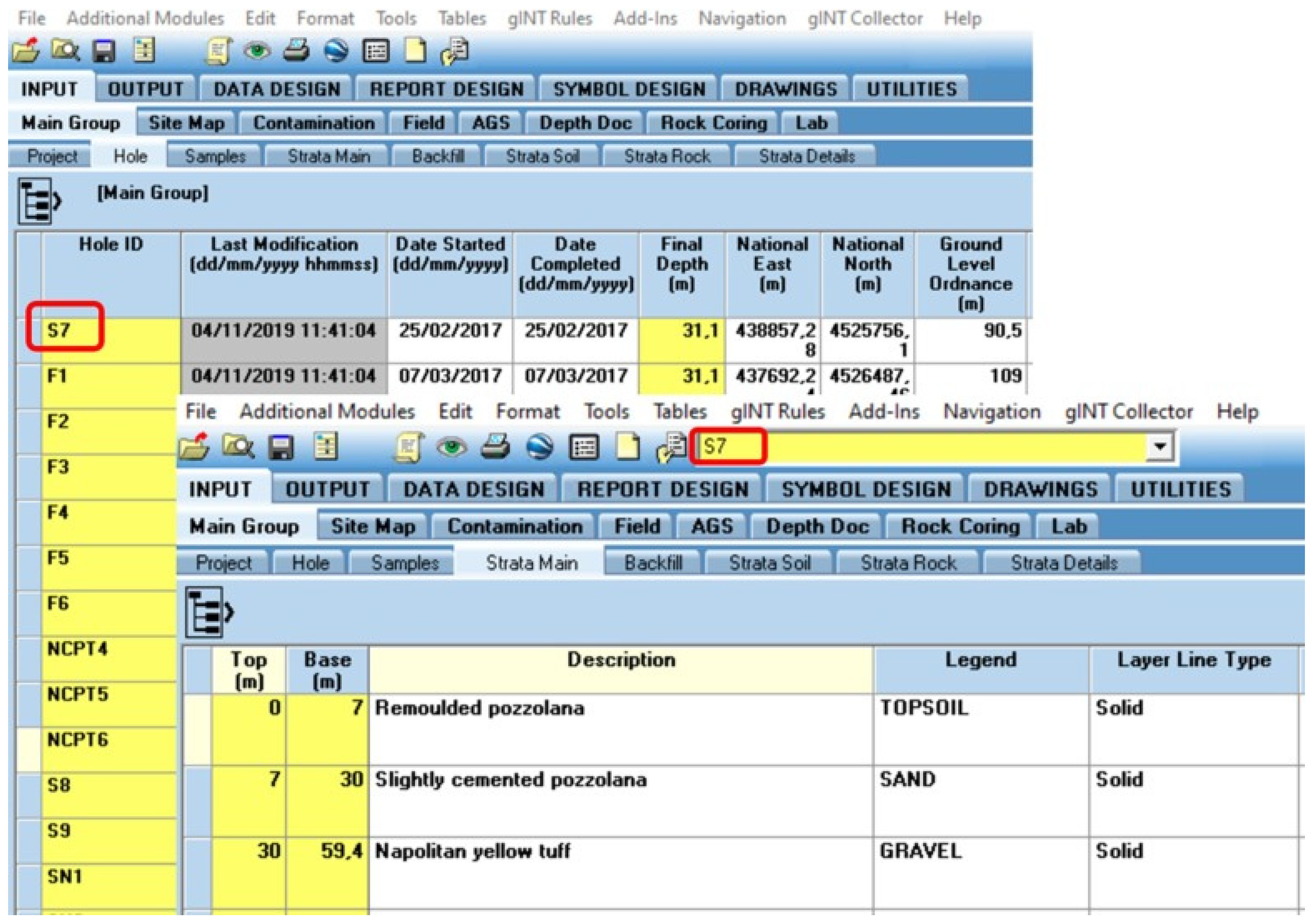
36]. Bentley’s gINT Professional software has been suggested for a BIM modeling of the planet [
36] as it manages geological and geotechnical soil data. This article recommends this software since it works with OpenRail and Plaxis. The gINT program imports the Plaxis subsurface and manually creates a database.
The geographical location of the logs (Hole in
Figure 11) and descriptions of their layers (Strata Main in
Figure 11) were introduced according to the INPUT major group displayed in
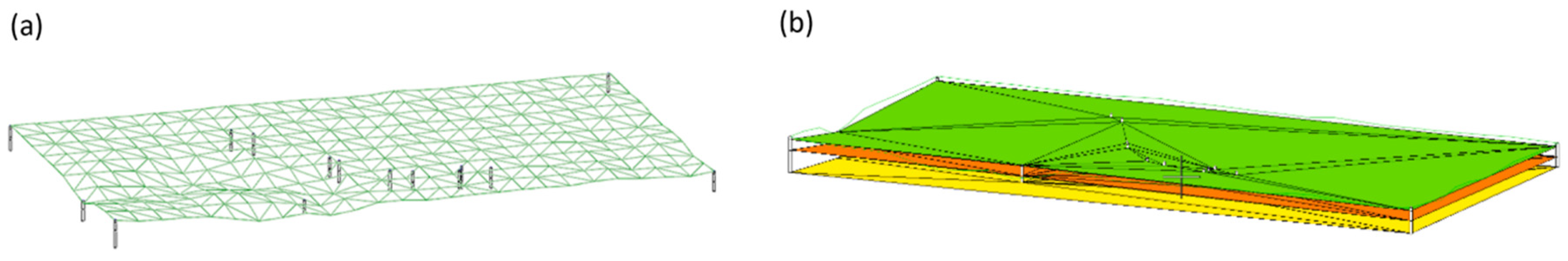
Figure 11. Each row and column in the data entry grid for the POINT Hole table shows data that corresponds to one borehole, and the lithology has a link to each well in the data entry grid for the POINT Strata Main table that determines the thickness and soil type of the three layers in this example. After the gINT project database was defined, the project data template was imported into OpenRail Designer to create the topographic and stratigraphic surfaces. Similar modeling programs show surfaces mathematically using TIN (triangulated irregular network) surfaces. For example,
Figure 12a demonstrates the topographic surface of this place, and
Figure 12b shows the intermediate surface layers, which are determined automatically by interpolating the top and bottom depths of each log layer.
Recently, there has been significant progress in geotechnical BIM, which is used in construction projects to model and visualize underground structures, reducing inaccuracies in the process. This practice is common in developed countries like the UK, Sweden, Australia, etc. However, in developing countries like Malaysia, the implementation of geotechnical BIM is still limited. Lee et al. [
3] looked at two case studies in Malaysia to examine the process of improving 3D subsurface models. In the local areas of the tropical region, there is a large amount of residual soil [
37]. There are challenges in the form of unstable geology, subsurface conditions, complex soil profiles and extreme climates that prevent the use of BIM technology in these areas [
38].
In Malaysia, soil survey information is usually provided in the American Geotechnical and Geological (AGS) Format in printed or electronic PDF format [
39]. For this reason, for data to be exchanged in a single platform for all stakeholders, extraction and digitization into a standard format must be conducted with this information. In 1991, a method called the “AGS format” was invented, which allowed the transfer of geological information between different programs in the geological field [
40]. This format has had several updates lately, and the latest updated version is 4.0.4. This method is important for the implementation of geotechnical BIM since, with its help, all participants in the geological and geotechnical fields can use a universal data entry format [
41]. Many geotechnical BIM programs are currently able to import AGS input data. This format provides data with unique legend codes for classifying the 159 soil material types. Each of these codes has been manually assigned to each soil type, given their geological characteristics.
An alternative method for integrating geotechnical data into BIM is the CSV format. In comparison, this format uses less data [
42]. Two files were made in this format—“Field Geological Descriptions “ and “Location Details”. The first file was applied to enter the borehole identity, the thickness of every ground level and the legend code with geological properties, and the second was for the coordinates, the depth of the end of the boreholes and the reduced layers. The researchers attempted to generalize the soil profiles given their prevailing compositions and SPT’N values to facilitate the modeling process [
43]. Thus, as a result, six types of soil in terms of composition—sand, clay, gravel, silt, hard layer, and stone and four types of cohesive soils in terms of stiffness were obtained. The correct interpretation and generalization of soils are strongly influenced by professional opinion and experience; therefore, consultations were held with specialists.
To create a topographic layer of a 3D subsoil model, obtaining the necessary data on coordinates and decrease in borehole levels from SI reports was necessary. The required data were obtained through interpolation from a 2D topographic map for boreholes that did not have this information. All the above was done in AGS and CSV formats [
44,
45].
3D subsurface modeling has made it easier and more efficient to interpret the soil profile, as the likelihood of inaccurate assessment of significant soil properties that can have a negative impact on geotechnical structures has been significantly reduced. Therefore, it is concluded that geotechnical BIM provides an accurate visualization (as far as possible) of the levels of the soil and the solid layer in a certain place.

 ,
, 


