1. Introduction
Today, there are many systems that have different functions depending on their field of application. Their common feature is a solution that meets the requirements set for their design. One of these areas is transport, specifically air transport. Airports are an essential part of air transport. Airports are complex structures consisting of buildings, hangars, runways, taxiways, services roads, etc. Given their number of air passengers, airports are subject to high-security requirements. This is ensured by various technologies and systems. A more detailed look at the function of the airport, specifically the function of Lublin Airport, can be found in the literature [
1]. Small airports are becoming increasingly popular, as evidenced by the development of the aviation market in Poland [
2].
For the proper functioning of some of these systems, the construction of maintenance shafts is necessary. An essential part of the manhole is its hatch, which must meet certain criteria. The airport itself has several requirements regarding manhole hatches. In addition, the relevant licenses and international standards need to be complied with in the design. A well-designed manhole hatch is crucial for airports in order to ensure safety and efficiency. Access hatches are designed to permit access to external and internal segments, such as electrical wiring, cables, and security systems. They not only provide maintenance support but also keep the components inside safe. Heavy-duty access hatches are used for outdoor applications such as runways, walkways, hangars, and aprons. When operating heavy aircraft as well as airport vehicles, manhole hatch solutions must be durable enough to withstand the loads.
As observed in the literature review, one of the most important parts of the structure is its reinforcement. This can be formed of profiles of different cross-sections. The most commonly used reinforcements are U- and L-type reinforcements. Based on the results of tests of the reinforcement in axial compression, it has been shown that this shape has a great influence on the lightweight construction of the hatch cover [
3]. The safety of the hatch is also a very important issue. From this point of view, the influence of the material used to ensure the safety of hatches was investigated. These hatches were later approved and certified [
4]. The design was also inspired by MacGregor’s research on special hatches used for container ships. In this research, the effects of the materials used on the long-term reliability and durability of the hatches were determined [
5]. The strength of the frame also has a great influence on the overall functionality and strength. This was observed in one of the strength analyses of the frame [
6].
The main objective of this study was to design and simulate the loading on a hatch intended to be used at an airport. The construction of the hatch took place near service roads for ground transport in the airport area. In the FEM analysis, we simulated load tests according to the EN 124-1 standard, which the hatch had to pass during the certification process. The successful analysis assumed that the hatch would be certified without problems and that it would be possible to produce it in series production.
2. Input Requirements for Hatch Design
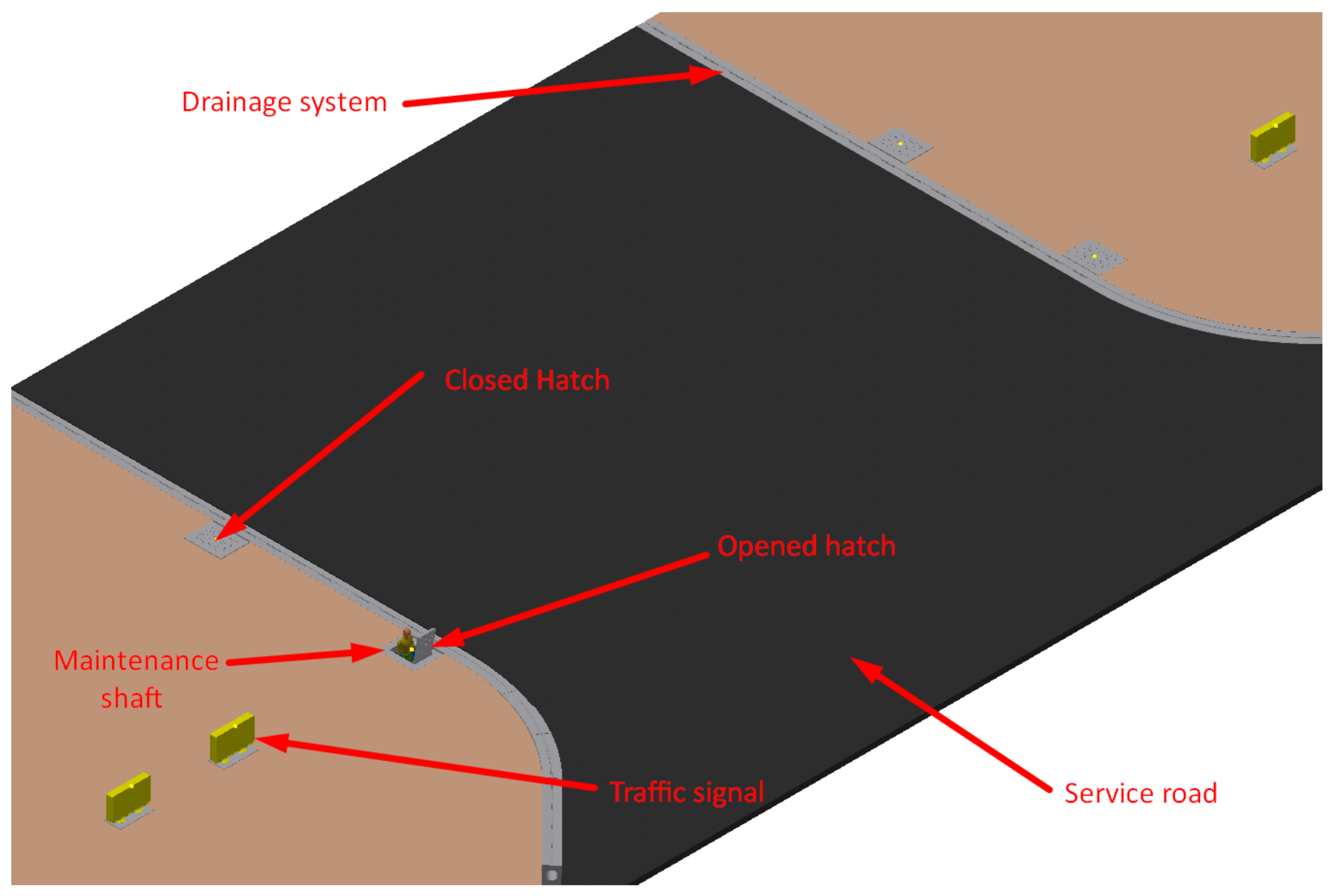
The hatch is located in the maintenance shaft. The hatch is situated close to the service roads in the airport, rendering it subject to higher transport safety requirements [
7]. There is a special drainage system around the service roads that is used to drain water from the service roads [
8,
9]. The maintenance shaft feeds the airport’s traffic and safety systems, such as traffic signals. A simplified model of part of the service road can be seen in
Figure 1. The 3D model was created using Autodesk Inventor.
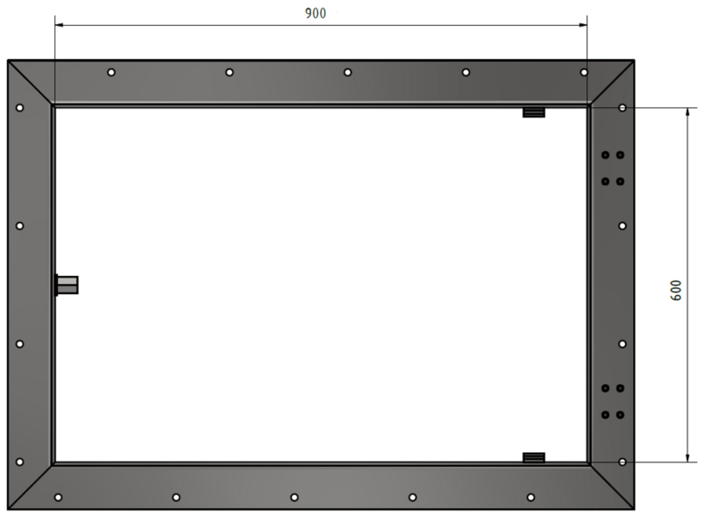
For transport safety, certain procedures and standards must be followed in the design of the manhole hatch. Another factor that influences the structural design is the customer’s requirements. The required dimensions of the maintenance hatch are 900 × 600 mm, as shown in
Figure 2.
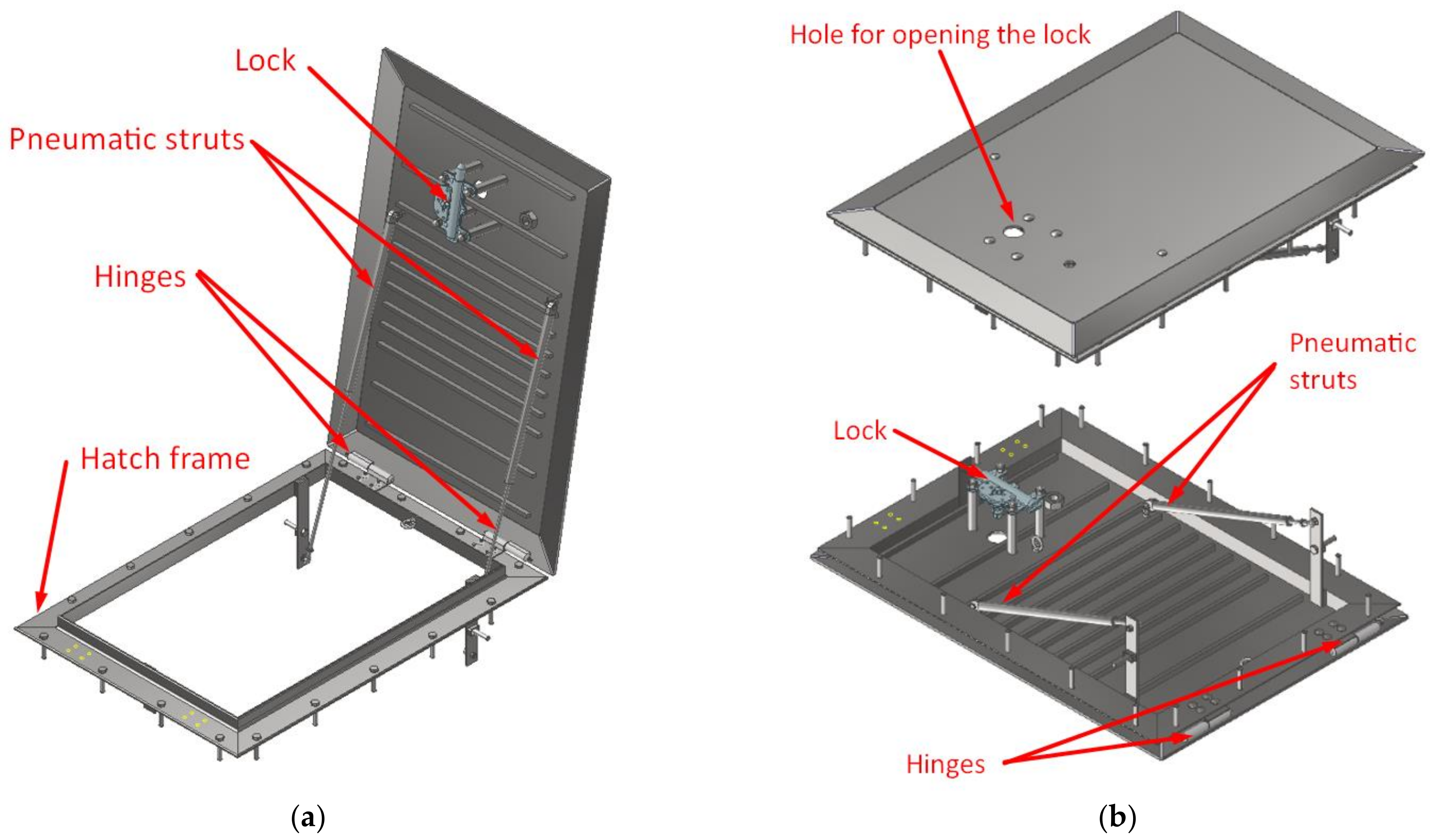
2.1. Lockability
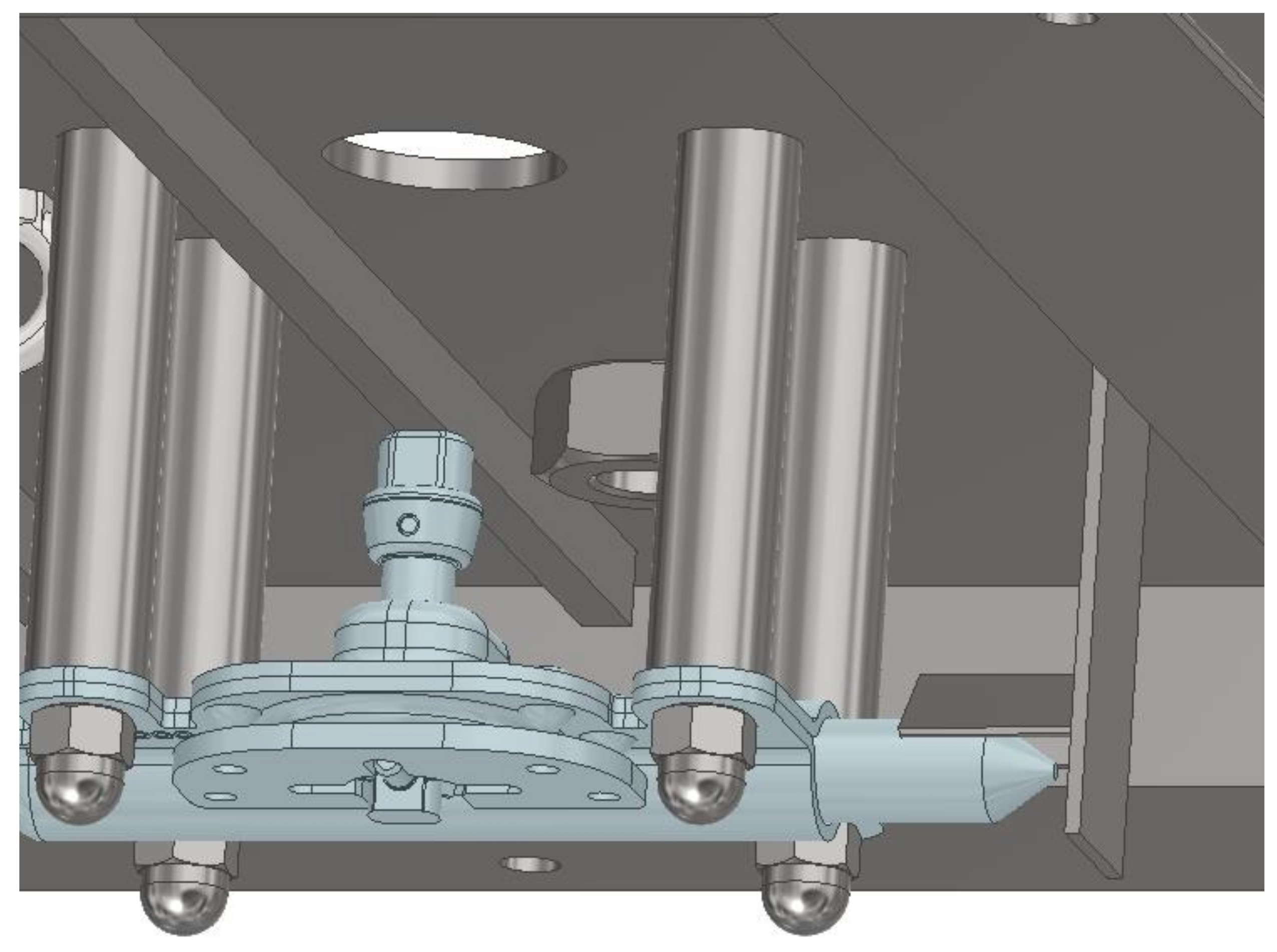
To ensure security and protection against vandalism, the locking system must be located deep enough to prevent it from being opened using any object other than the original key, as shown in
Figure 3. The lock used on the hatch must be the same as that used for other security devices at the airport (the US 250—Type II hatch locking system). This system also prevents the hatch from spontaneously popping open during an accidental passage [
7]. In the event of flooding, it protects against the dropping and opening of the hatch. At the same time, it ensures trouble-free access for authorized persons, as the system is tested in extreme climatic conditions (frost, dust, snow, and salt). This locking system is also specially designed to protect manholes from the placement of hazardous materials during terrorist attacks [
7,
10].
2.2. Maximum Lifting Force
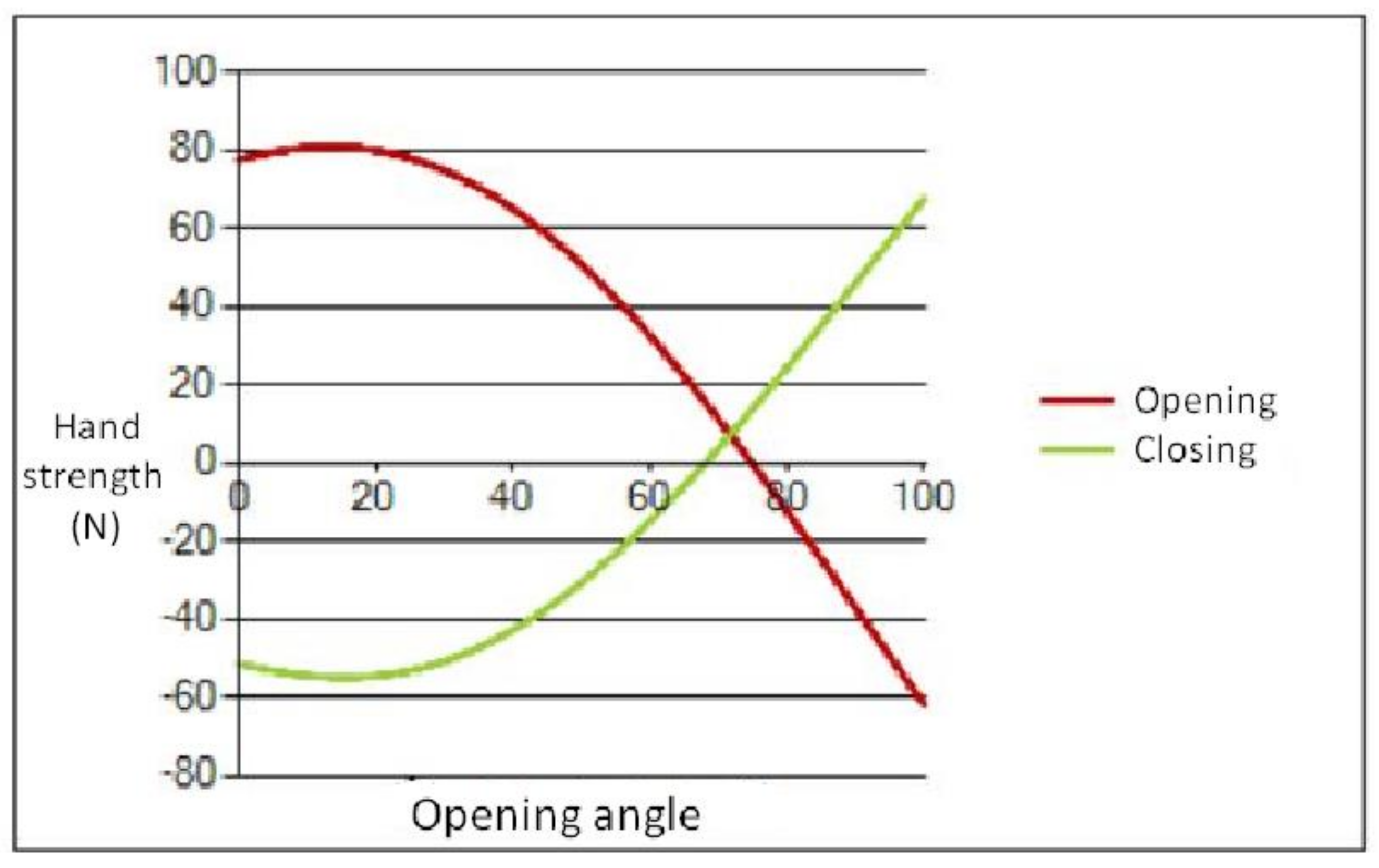
The maximum lifting force to be applied by the operator when opening the hatch was set as 250 N. Pneumatic struts on both sides of the frame are designed for the purpose of ease of operation [
11]. To calculate the correct lifting force of the struts, it is necessary to know the weight of the hatch, which is 45 kg, and the location of its center of gravity. The distance to the attachment point with which the hatch is lifted is also very important. Based on the evaluation of all the input parameters, two gas struts of designation 75127425/1-92264-92,264 were used. The struts have a piston rod diameter of 10 mm and a gas cylinder diameter of 22 mm.
Figure 4 shows an illustration of the hatch lifting force analysis. The result of using gas struts is that the maximum force required to open the hatch is 82 N. The maximum force required by the operator to close the hatch is 58 N.
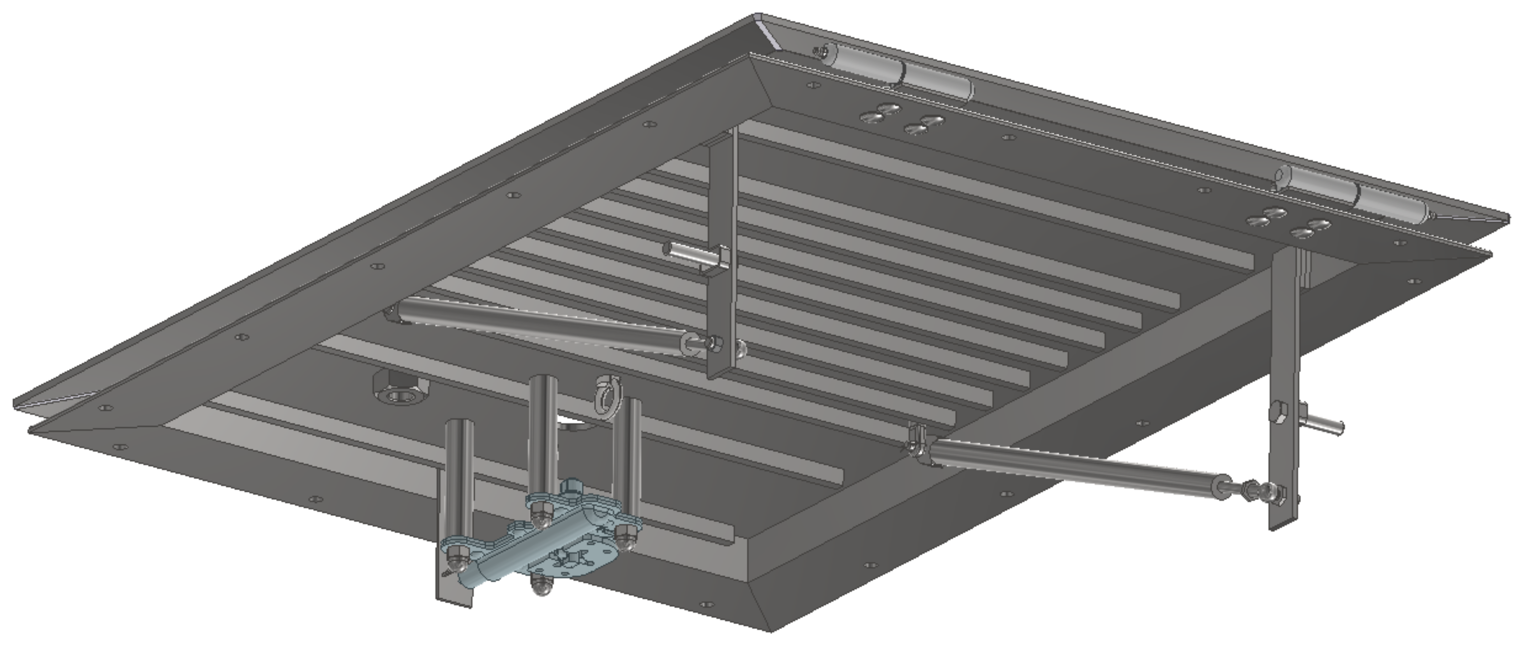
2.3. Hinge Opening
The hatch opens via hinges. The hinges are located on the shorter side, with a width of 600 mm (
Figure 5). A ladder is located under the hatch. For better long-term maintenance, the hinges should be fitted with a lubricator [
12]. Based on all the input parameters, welding hinges of type K0984.020150012 with lubricator DIN 71412-D, made of galvanized steel, were selected. These hinges have a pin diameter of 13 mm.
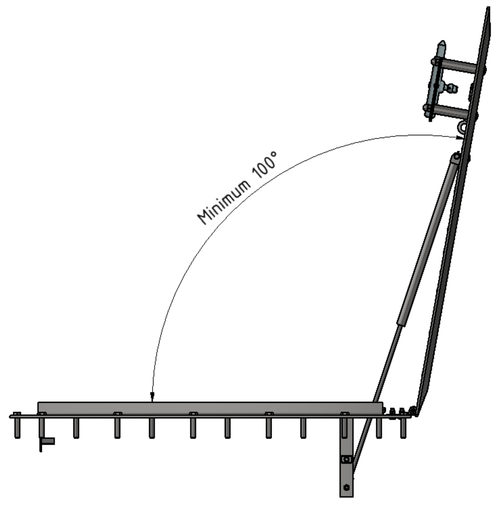
2.4. Hatch Opening Angle
Securing the hatch against spontaneous closure can be achieved according to ČSN EN 124 by applying an opening angle of the hatch that is greater than 100° from the horizontal plane (
Figure 6), if additional supports are not used. At the same time, a safety element was designed—a chain preventing the hatch from opening completely. The use of a chain that prevents the hatch from opening completely can also considerably prolong the life of the gas struts, which, due to the use of the chain, never reach their maximum extension. Chain eyelets were screwed onto the hatch, and a chain of the required length was fitted.
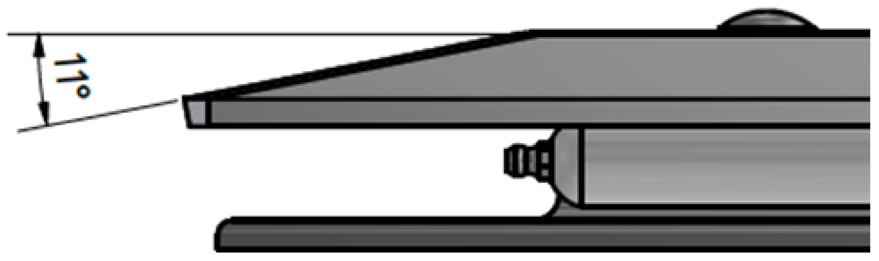
2.5. Waterproofing
To ensure waterproofness, the edges of the hatch plate must be bent. In this case, we propose bending the edges at an angle of 11° (
Figure 7). With the hatch sheeting extending over the edge, the protection of the functional elements (hinges and pneumatic struts) against direct rain is ensured [
13]. This will prolong their service life.
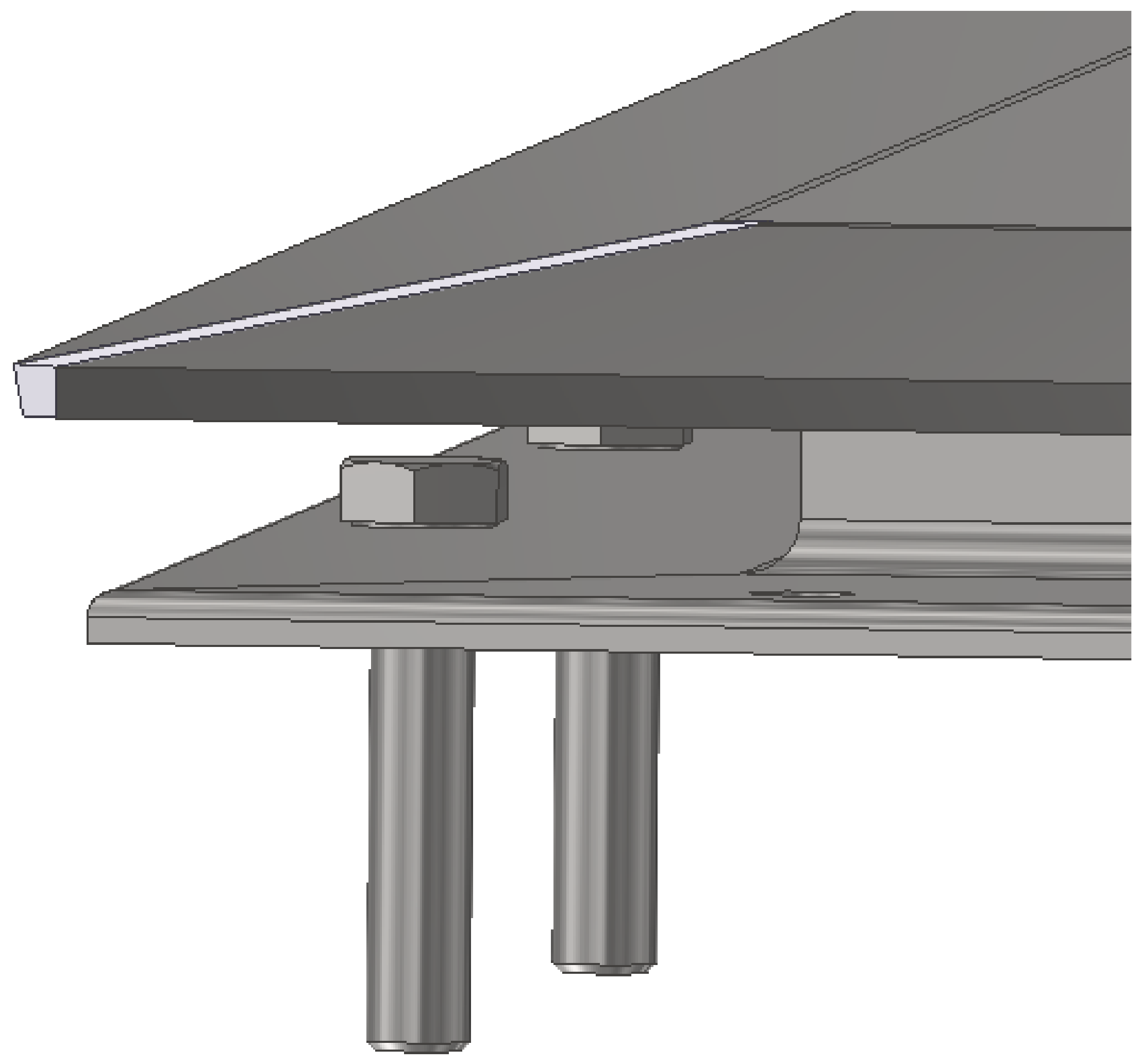
2.6. Fixing the Hatch Frame
The frame must be fixed to the top landing surface of the shaft. The impossibility of dismantling must be resolved to prevent theft and unauthorized access. Therefore, the bolts of the frame should be covered with a cover so that they cannot be accessed without opening (
Figure 8) [
14]. However, at the same time, the bolts must be as far as possible from the edge of the shaft [
4]. This is to reduce the risk of the shaft’s concrete peeling off.
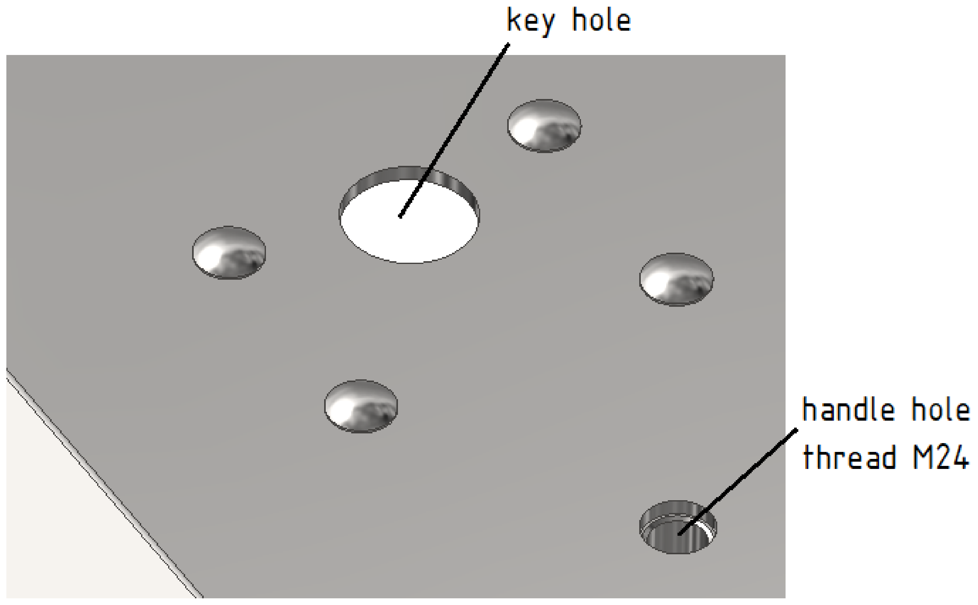
2.7. Lifting the Hatch
The lifting of the hatch is realized using a standardized handle. It is necessary to create an M24 thread to screw in the standardized handle (
Figure 9). This is used to open the hatch after unlocking the lock.
3. Load Test of the Hatch
Regarding safety, the design and testing of the hatch are subject to certain standards and requirements [
15]. These are addressed in EN 124-1. To obtain preliminary results, the load is simulated using ANSYS software. Later, load tests are carried out in a certified test laboratory.
Tests are carried out on the inlet grates and manholes in complete operational condition. The equipment to be tested is new, has not been subjected to any other load tests, and is selected at random. The dimensions and shapes of the test bodies correspond to those shown in
Table 1. For this design, the clearance dimension is
CO = 600.
For the load-bearing capacity tests of inlet grilles and hatches made of different materials with a clear
CO equal to or greater than 250 mm, all classes must withstand the test loads in
Table 2. The proposed manhole cover belongs to Group A 15.
When testing inlet grilles and hatches using
FP (
) loads, the permanent conversion must not exceed the values given in
Table 2.
The point load of the hatch to be tested is 15 kN for Class A15. The maximum permissible permanent redesign is calculated according to the formula in
Table 3:
where
a (mm)—the maximum permissible permanent redesign,
Table 3.
Permissible permanent set according to EN 124-1.
Table 3.
Permissible permanent set according to EN 124-1.
| Class | Permissible Permanent Set |
|---|
| A 15 and B 125 | |
| C 250 up to F 900 |
When secured according to 7.8 (a) or 7.8 (c) |
When secured according to 7.8 (b) |
4. Load Test of the Hatch Frame
For the purpose of safety, the design and testing of the hatch are subject to certain standards and requirements. These are addressed in EN 124-1. For the preliminary results, the load is simulated in the same way as in the first load test using ANSYS software [
16,
17]. Later, the load tests are carried out in a certified test laboratory [
18].
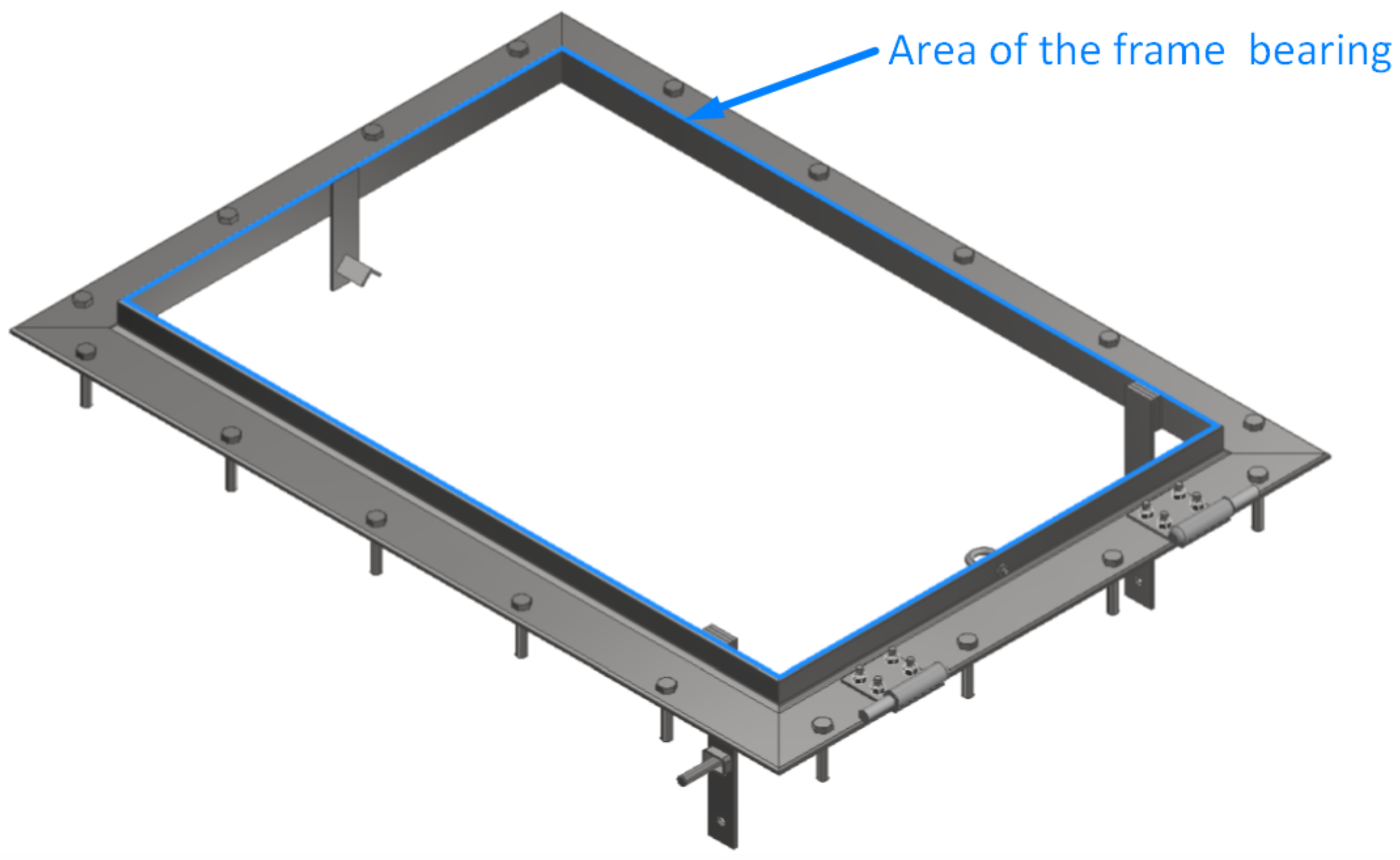
The frame-bearing area is designed so that the pressure in the frame bearing on the substrate P
b under the test load
FT does not exceed 7.5 N/mm
2 on average to ensure stability under normal operating conditions. Area
Ab is the area of the frame bearing, which can be seen in
Figure 10 as the area marked in blue. The size of this area was determined using Autodesk Inventor; its value is 9036.4 mm
2. The pressure in the fit of the frame to the substrate must be calculated using the following formula:
Based on these calculations, the actual pressure in the frame bearing on the substrate Pb is only 1.66 N/mm2. This value safely meets the standard, which permits a maximum Pb pressure of 7.5 N/mm2.
5. Hatch Structural Design
When constructing the hatch (
Figure 11), care must be taken to consider the operating conditions and requirements already mentioned. The main material chosen for the hatch’s construction (based on the ANSYS analysis) is a 6 mm thick structural steel plate. The material has a tensile yield strength of 250 MPa and an ultimate tensile strength of 460 MPa. The density of the material is 7850 kg/m
3. The featured construction can be used alongside service roads for ground transport in the aerodrome area or alongside taxiways intended for light aircraft only. The hatch cannot be used alongside taxiways on which heavy aircraft operate. Due to the requirement for waterproofness and the risk of damage in the event of crash-landing gear wheel run-up, the edges of the hatch are bent at an angle of 11°. The body of the hatch is cross-reinforced with 12 pieces of 15 × 10 mm steel flat bars. When closed, the entire hatch is supported by the edges of the frame. The structural design was created using Autodesk Inventor.
To verify the functionality of the hatch and to save money, static analysis was performed using ANSYS 2023 R1 before production. Through the static analysis, it was possible to optimize the dimensions of the blanks and, therefore, to select the smallest possible sheet thickness and the thinnest possible reinforcement [
19,
20]. The optimization was performed to save weight and reduce the production and assembly costs that would have been incurred with the planned larger number of pieces intended to be produced [
21].
6. Results
Based on the input conditions, a permanent redesign stress test was simulated in ANSYS. To simplify and shorten the whole simulation process, the input model was modified [
22,
23]. The frame geometry was simplified to include the hatch contact surfaces alone [
24].
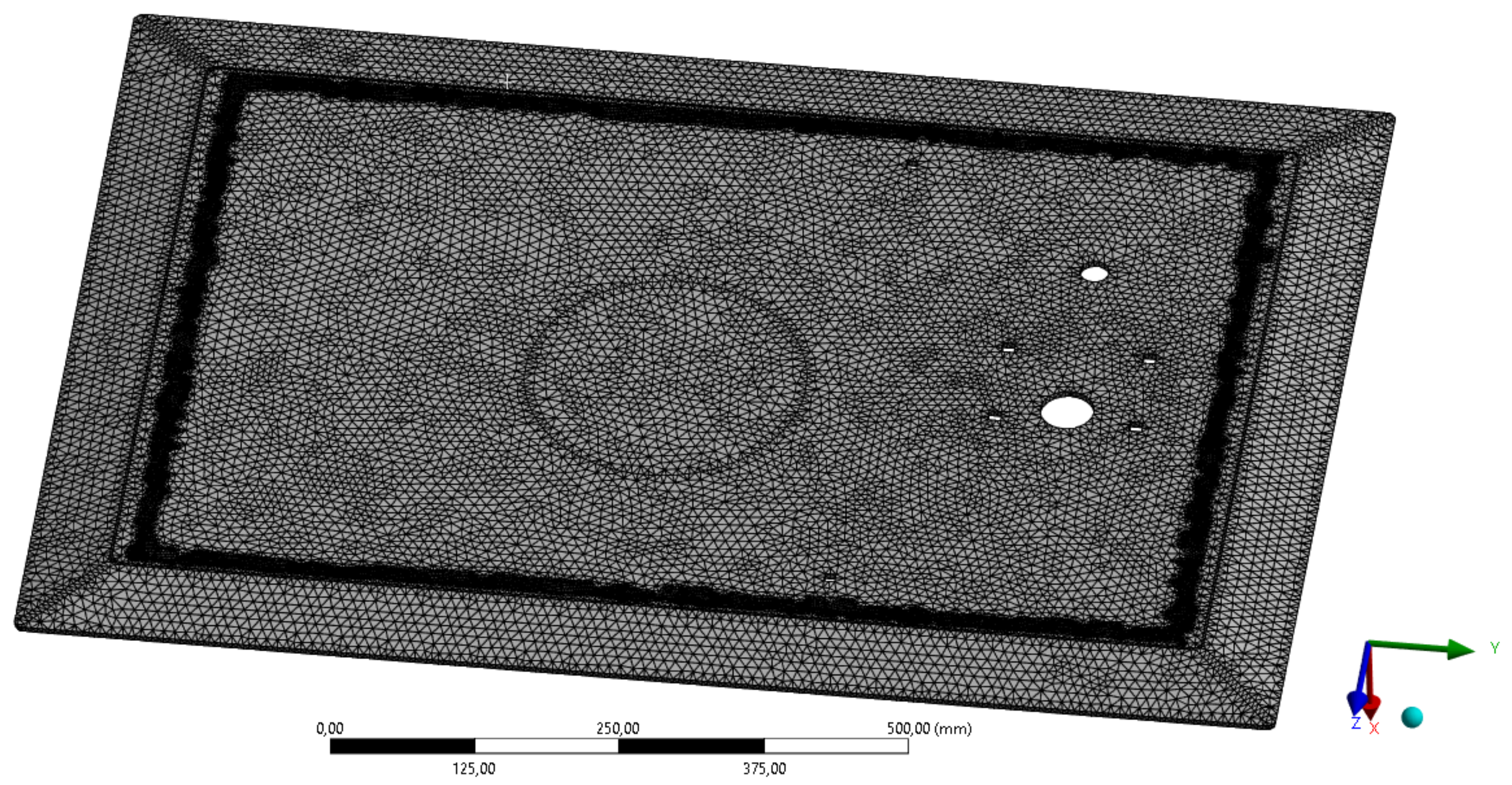
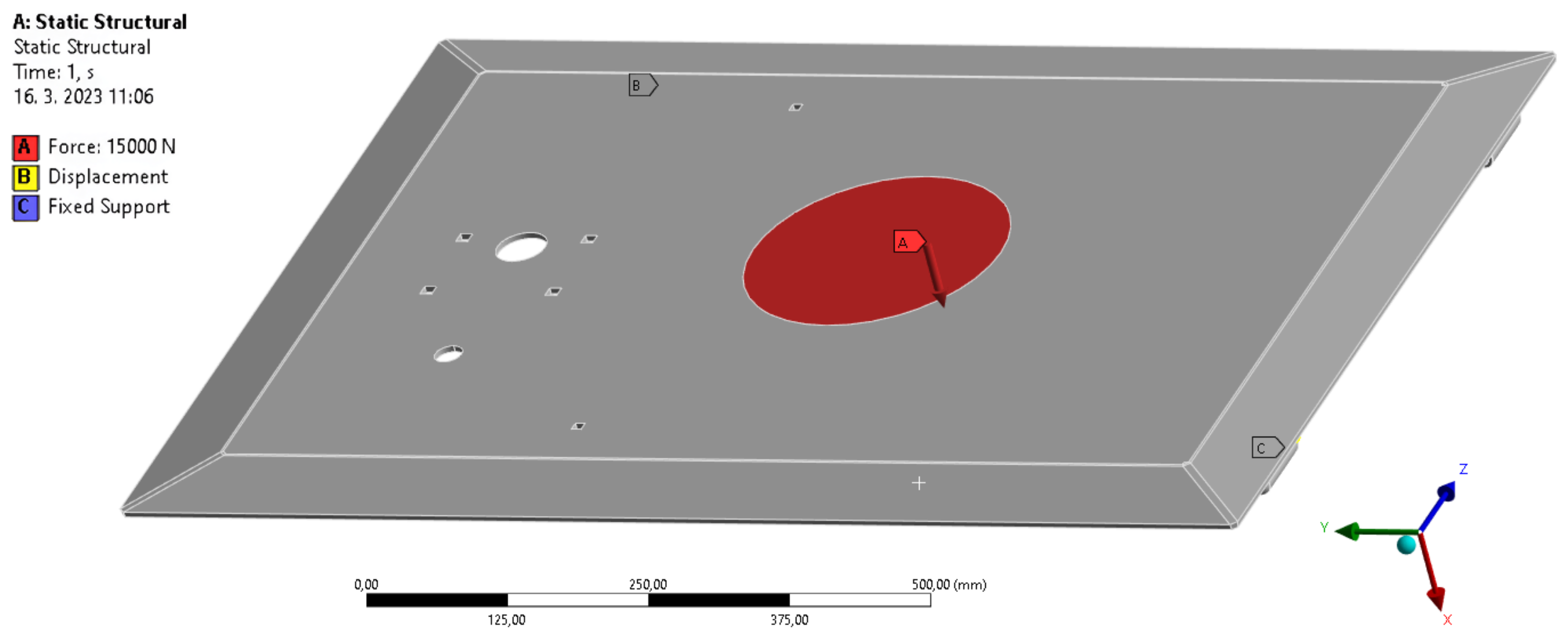
In the analysis, a load force of 15,000 N was simulated, chosen based on data from EN 124-1. In
Figure 12, one can see the input parameters for the test, the mesh, and the size and location of the test body, which correspond to EN 124-1. The size of the elements on the mesh was chosen to be 5 mm [
25,
26]. The total number of elements on the mesh is 705,410. The total number of nodes is 159,276. The mesh is densified at the connection point to the contact surfaces for more accurate results [
27,
28]. All the values can be seen in
Table 4.
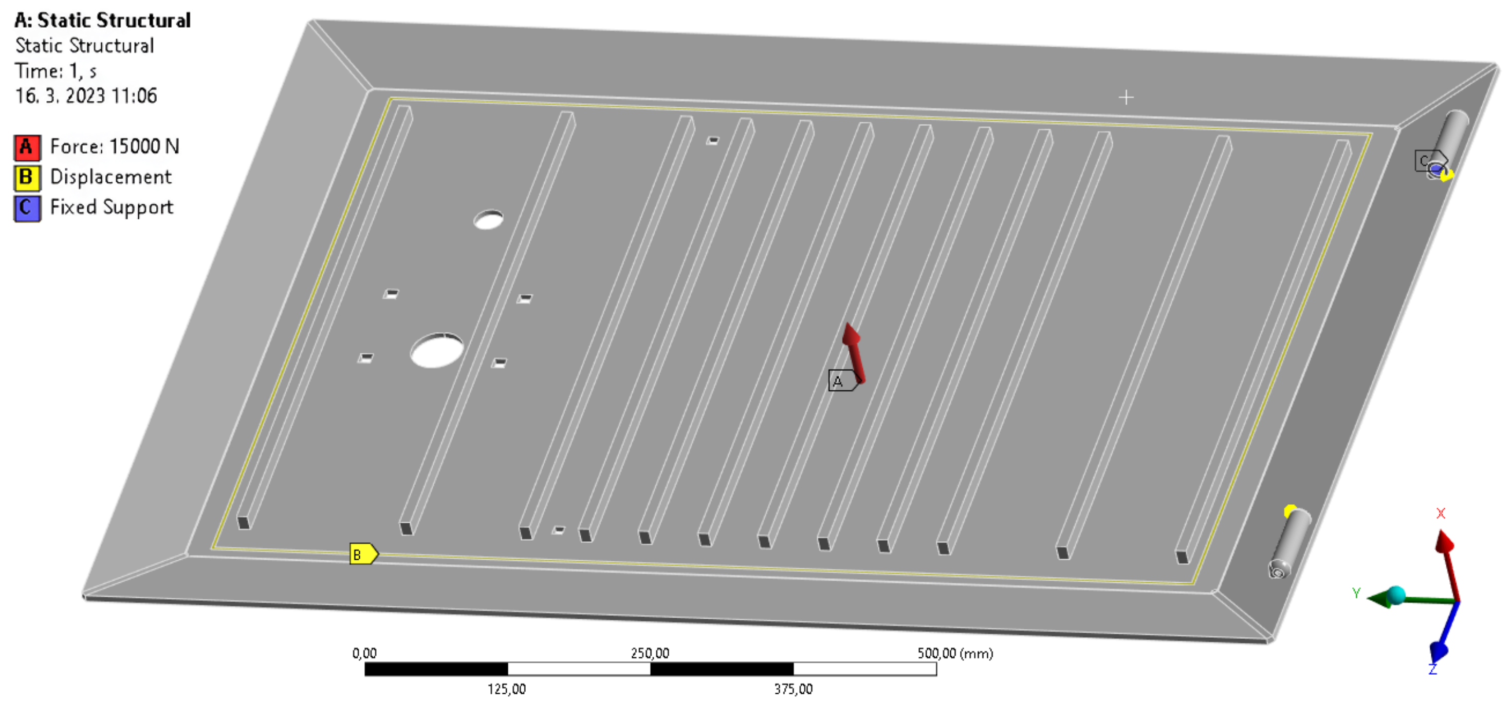
The applied boundary conditions are shown in
Figure 13 and
Figure 14. The applied force is located in the center of the hatch according to EN 124-1. For this reason, the force is applied to the circular surface in the direction of the Y-axis. The cover has all the degrees of freedom removed from the hinges, and at the point of contact with the base, the degree of freedom is removed in the direction of the X-axis. This contact surface will carry the main part of the load; therefore, this part features the greatest tension.
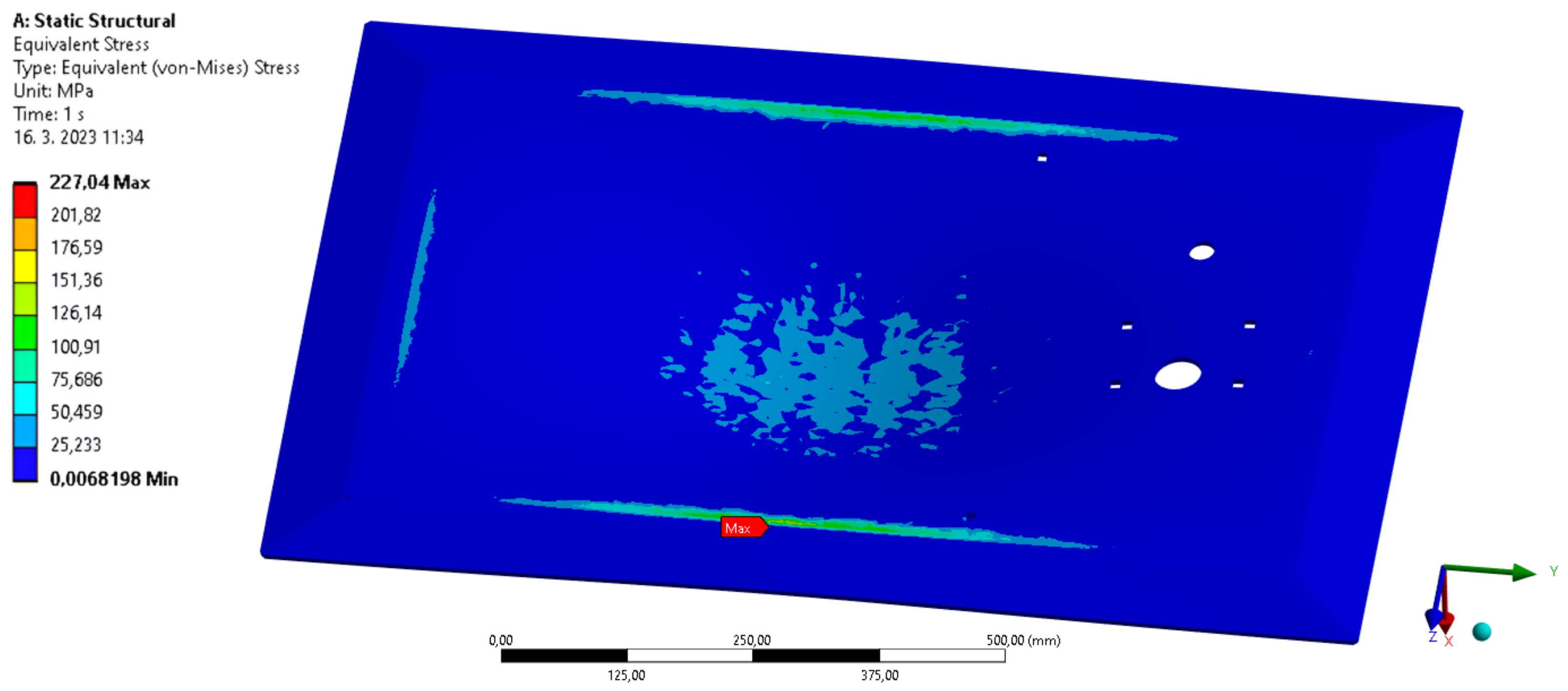
The results of the ANSYS permanent redesign stress test form two parts. The first part is the stress analysis, which can be seen in
Figure 15.
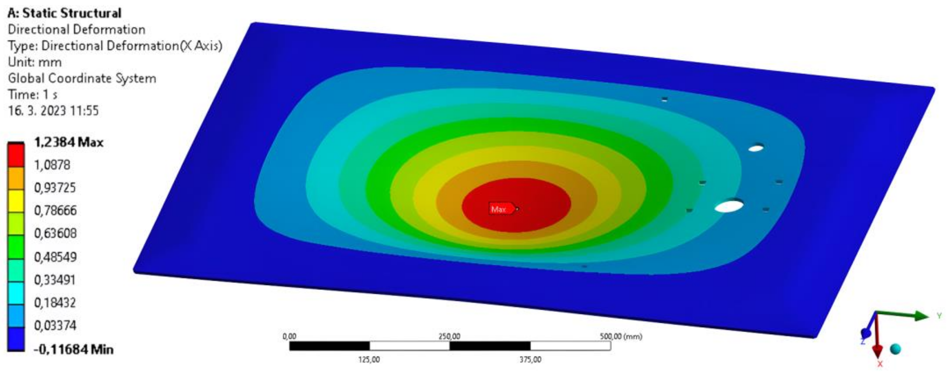
The second part, including the results of the permanent redesign load test, concerns the permanent redesign deformation analysis, which can be seen in
Figure 16.
7. Conclusions
In the stress analysis, it was seen that the maximum pressure generated in the hatch is 227 MPa. Since the tensile yield strength is 250 MPa, this value is satisfactory. The deformation analysis showed that the hatch deflects only 1.2384 mm at the point of maximum deflection. Since the maximum allowable deflection value, calculated based on EN 124-1, is 6 mm, it can be concluded that the deflection value is satisfactory.
Based on all the calculations and analyses that were performed, the hatch, which is intended to be used at the airport, meets all the parameters set for it, with an emphasis on the safety of transport. Based on the ANSYS analyses, it passes the stress tests that it must undergo for its certification. After successfully passing the stress tests in a certified laboratory, the hatch can enter series production.
With better material qualities, we will be able to optimize the sheet thickness of this hatch if we conduct further studies on alternative material options. Moreover, we can lower the number of stiffeners. We will add more factors to the simulations, including the weld strength and load capacity of the attachment bolts, as well as the number of strains on the hinges.
Author Contributions
Conceptualization, J.F., D.Č. and J.J.; methodology, J.F. and S.H.; software, J.J., J.F. and P.M.; validation, S.H. and P.M.; formal analysis, J.F. and D.Č.; investigation, J.F. and D.Č.; resources, J.F., J.J. and P.M.; data curation, J.F. and J.J.; writing—original draft preparation, J.F. and D.Č.; writing—review and editing, J.J., J.F. and D.Č.; visualization, J.J. and P.M. All authors have read and agreed to the published version of the manuscript.
Funding
This research received no external funding.
Data Availability Statement
Not applicable.
Conflicts of Interest
The authors declare no conflict of interest.
References
- Nieoczym, A.; Caban, J.; Bartuška, L. The Functioning of the Regional Airport on the Example of Lublin Airport. MATEC Web Conf. 2018, 236, 02003. [Google Scholar] [CrossRef]
- Caban, J.; Ignaciuk, P.; Stopka, O.; Zarajczyk, J. Aviation market in Poland in 2000–2007. MATEC Web Conf. 2018, 236, 02002. [Google Scholar] [CrossRef] [Green Version]
- Shi, G.-J.; Gao, D.-W. Ultimate strength of U-type stiffened panels for hatch covers used in ship cargo holds. Ships Offshore Struct. 2021, 16, 280–291. [Google Scholar] [CrossRef]
- Noury, P.; Hansen, R.E.; Høyning, B. Composite hatch cover for bulk carriers. In Proceedings of the 20th International Conference on Composite Materials, Copenhagen, Danemark, 19–24 July 2015. [Google Scholar]
- Strosley, A. MER—Marine Engineers Review; Issue FEB, Millipore: Burlington, MA, USA, 2002; pp. 24–26. [Google Scholar]
- Caban, J.; Nieoczym, A.; Gardyński, L. Strength analysis of a container semi-truck frame. Eng. Fail. Anal. 2021, 127, 105487. [Google Scholar] [CrossRef]
- Deng, W.; Zhang, L.; Zhou, X.; Zhou, Y.; Sun, Y.; Zhu, W.; Chen, H.; Deng, W.; Chen, H.; Zhao, H. Multi-strategy particle swarm and ant colony hybrid optimization for airport taxiway planning problem. Inf. Sci. 2022, 612, 576–593. [Google Scholar] [CrossRef]
- Peng, J.; Yu, L.; Zhong, X.; Dong, T. Study on Runoff Control Effect of Different Drainage Schemes in Sponge Airport. Water Resour. Manag. 2022, 36, 1043–1055. [Google Scholar] [CrossRef]
- Geng, L.; Hu, J. Construction and design of whole site drainage system of sponge airport based on BIM. In Second International Conference on Sensors and Information Technology (ICSI 2022); SPIE: Washington, DC, USA, 2022; Volume 12248, pp. 151–156. [Google Scholar]
- Burlov, V.; Gryzunov, V.; Koryakina, A.; Ukraintseva, D. Management of the Airport Security Process Based on the Conservation Law of the Object’s Integrity. In International Scientific Siberian Transport Forum TransSiberia-2021; Springer International Publishing: Cham, The Switzerland, March 2022; Volume 1, pp. 1281–1289. [Google Scholar] [CrossRef]
- Jiang, M.; Rui, X.; Yang, F.; Zhu, W.; Zhu, H.; Han, W. Design and dynamic performance research of MR hydro-pneumatic spring based on multi-physics coupling model. Nonlinear Dyn. 2023, 235, 1–25. [Google Scholar] [CrossRef]
- Olver, A.V. Gear lubrication—A review. Proc. Inst. Mech. Eng. Part J J. Eng. Tribol. 2002, 216, 255–267. [Google Scholar] [CrossRef]
- Tyrrell, J. Waterproofing rules. Plumb. Connect. 2014, 2014, 30–36. [Google Scholar]
- Kanaval, J.; Cézová, E.; Starý, F.; Dynybyl, V.; Klíma, V. Experimental analysis of modern screw fasteners. In Proceedings of the Experimental Stress Analysis—56th International Scientific Conference, EAN 2018—Conference Proceedings, Harrachov, Czech Republic, 5–7 June 2018; pp. 184–191. [Google Scholar]
- Kanaval, J.; Cezova, E. Strength calculation of prestressed bolted connections analysis using available computational software and fem method. In Proceedings of the Experimental Stress Analysis—58th International Scientific Conference, EAN 2020, Online, Czech Republic, 19–22 October 2020; pp. 195–203. [Google Scholar]
- Middendrop, P.; Bermingham, P.; Kuiper, B. Statnamic load testing of foundation piles. In Application of Stress-Wave Theory to Piles; Routledge: Abingdon, UK, 2022; pp. 581–588. [Google Scholar]
- Dižo, J.; Harušinec, J.; Blatnický, M. Structural Analysis of a Modified Freight Wagon Bogie Frame. MATEC Web Conf. 2018, 134, 00010. [Google Scholar] [CrossRef]
- Drbúl, M.; Martikáň, P.; Bronček, J.; Litvaj, I.; Svobodova, J. Analysis of roughness profile on curved surfaces. MATEC Web Conf. 2018, 244, 01024. [Google Scholar] [CrossRef]
- Luamba, E.S.; de Paiva, J.B. Static analysis of axially loaded piles in multilayered soils using a BEM/FEM formulation. Eng. Anal. Bound. Elem. 2022, 135, 63–72. [Google Scholar] [CrossRef]
- Raj, E.F.I.; Appadurai, M. Static 2D-Finite Element Analysis of Eccentricity Fault in Induction Motor. In Smart Technologies for Energy, Environment and Sustainable Development; Volume 1: Select Proceedings of ICSTEESD; Springer Nature Singapore: Singapore, 2020; pp. 409–422. [Google Scholar] [CrossRef]
- Stano, P.G. Lattice Structures 3D Modeling and Static Analysis. Doctoral Dissertation, Politecnico di Torino, Torino, Italy, 2022. [Google Scholar]
- Tomasikova, M.; Tropp, M.; Gajdosik, T.; Krzywonos, L.; Brumercik, F. Analysis of Transport Mechatronic System Properties. Procedia Eng. 2017, 192, 881–886. [Google Scholar] [CrossRef]
- Tucho, A.; Indraratna, B.; Ngo, T. Stress-deformation analysis of rail substructure under moving wheel load. Transp. Geotech. 2022, 36, 100805. [Google Scholar] [CrossRef]
- Dundar, A.; Gao, J.; Tao, A.; Catanzaro, B. Fine detailed texture learning for 3d meshes with generative models. arXiv 2022, arXiv:2203.09362. [Google Scholar]
- Tajdari, F.; Kwa, F.; Versteegh, C.; Huysmans, T.; Song, Y. Dynamic 3d mesh reconstruction based on nonrigid iterative closest-farthest points registration. In International Design Engineering Technical Conferences and Computers and Information in Engineering Conference; American Society of Mechanical Engineers: New York, NY, USA, August 2022; Volume 86212, p. V002T02A051. [Google Scholar]
- ALfarasani, D.A.; Sweetman, T.; Lai, Y.K.; Rosin, P.L. Learning to predict 3D Mesh saliency. In 2022 26th International Conference on Pattern Recognition (ICPR); IEEE: Piscataway, NJ, USA, August 2022; pp. 4023–4029. [Google Scholar]
- Majchrák, M.; Kohár, R.; Kajan, J.; Skyba, R. 3D Meshing Methods of Ball-Rolling Bearings. Transp. Res. Procedia 2019, 40, 784–791. [Google Scholar] [CrossRef]
- Dižo, J. Analysis of a goods wagon running on a railway test track. Manuf. Technol. 2016, 16, 667–672. [Google Scholar] [CrossRef]
| Disclaimer/Publisher’s Note: The statements, opinions and data contained in all publications are solely those of the individual author(s) and contributor(s) and not of MDPI and/or the editor(s). MDPI and/or the editor(s) disclaim responsibility for any injury to people or property resulting from any ideas, methods, instructions or products referred to in the content. |
© 2023 by the authors. Licensee MDPI, Basel, Switzerland. This article is an open access article distributed under the terms and conditions of the Creative Commons Attribution (CC BY) license (https://creativecommons.org/licenses/by/4.0/).


