Article

Development of an Engineered Slurry-Infiltrated Fibrous Concrete: Experimental and Modelling Approaches

by
Mohammed H. Yas
1,*,
Mohammed M. Kadhum
2 and
Watheq G. B. Al-Dhufairi
1,3
1
Faculty of Engineering, Razi University, Kermanshah 67146, Iran
2
Faculty of Engineering, University of Babylon, Babylon 50015, Iraq
3
Oil Products Distribution Company, Ministry of Oil, Baghdad 10011, Iraq
*
Author to whom correspondence should be addressed.
Infrastructures 2023, 8(2), 19; https://doi.org/10.3390/infrastructures8020019
Submission received: 19 November 2022 / Revised: 27 December 2022 / Accepted: 5 January 2023 / Published: 31 January 2023

Abstract

:
Concrete is the central pile for the infrastructure that maintains civilisation and human life. The concrete industry faces many challenges, including improving mechanical properties, eco-friendliness, and durability. In this context, the present study focuses on evaluating and modelling themechanical properties of engineered concrete, namely slurry-infiltrated fibrous concrete (SIFCON). The main experiments will be devoted to measuring and modelling the failures of slabs made from SIFCON under two loading systems, namely static and impact loading systems. The model was developed using a non-linear finite element analysis. The experiments considered the influence of the geometry of the reinforcement steel fibres (hook-end fibres, microfibres, and combined hook-end and microfibres), sizes of fibres, and slab dimensions. The outcomes of this investigation showed that increasing the slab’s thickness enhances the load-bearing capacity of the SIFCON slab, and the microfibres and combined hook-end and microfibres improved the load-bearing capacity of the slab compared to the hook-end fibre. Generally, it was noticed that the outcomes of the experiments agreed with the modelling outcomes. Nevertheless, it was noticed that experimentally measured axial deformation was more significant than the predicted axial deformation. In summary, the difference between experimental and modelling outcomes was 1.1–10.2%, with a standard deviation of 0.0264. Based on the excellent ability of SIFCON to resist impacts and dynamic loads, it is recommended to be used in pavements, military structures, nuclear reactor walls, and in areas subjected to high bending moments, such as corner connections subjected to opening bending moments.

1. Introduction

The challenges of the popular needs of civil structures require various construction materials with enhanced characteristics such as high abrasion resistance, better compressive strength, and modified stiffness [1,2]. SIFCON is a promising type of concrete because it enjoys excellent energy absorption, compressive and flexure strengths, shear resistance, stiffness, and ductility [3,4]. SIFCON was successfully implemented in several civil structures like pavements and other structures that are affected by sudden and dynamic loading. Examples of such buildings are military structures, stone shelters in mountain terrains, and nuclear reactor walls which may be affected by bombs, debris flows, trucks, aeroplanes, etc. [5,6,7]. Additionally, because of the excellent ductility and impact resistance properties of SIFCON, it was used to construct many structural parts that are subjected to extreme and sudden loads during their service life [8,9].
SIFCON is classified as a new and distinct category of fibre-reinforced concrete (FRC) with high fibre content [10,11]. However, SIFCON differs from other FRC in terms of production methods and fibre content [12,13]. Generally, about 1% to 3% of fibre content is implemented in normal FRC, whereas SIFCON contains between 5% and 20% of fibre content. The content of the fibre in the SIFCON depends on many aspects such as fibre shape and diameter and other fibre physical characteristics. In addition, the orientation of fibres, the packing methods, the sizes of the mould, and the degree of shaking have a significant impact on the percentage of fibre used as well as on the resulting concrete.
The literature shows many research efforts to investigate the properties and/or eco-friendliness of SIFCON. For example, Soylu and Bingöl [14] studied the effects of different ratios of steel fibres (0 to 12%) on the properties of SIFCON. The SIDCON samples were cured for 7 and 28 days before calculating the compressive and flexural strengths, and it was noticed that the compressive and flexural strengths of SIFCON improved when the steel fibre ratio increased up to 8% but decreased after this ratio. The authors explained the decrease in strength reduction by minimising the flow of mortar between the fibres. Recycling of waste materials in SIFCON was also investigated in the literature. For example, Aygörmez, et al. [15] enhanced the eco-friendliness of SIFCON by using metakaolins, fly ash and white cement to replace 25–50% of ordinary Portland cement (OPC) in SIFCON, which reduces CO2 emissions. The samples of SIFCON were cured for 7 and 28 days before testing flexural and compressive strengths. It was noticed that the flexural and compressive strengths increased with the use of metakaolin but decreased with the use of fly ash. The authors explained the decrease in the strength with the use of fly ash by the incomplete hydration of the fly ash by the testing time. Other studies studied the effects of the fibers shape on the properties of SIFCON [16,17]. For example, Ali and Riyadh [18] studied the effects of shape and type of fibres on the properties of SIFCON by examining samples containing 6% hooked-end steel fibres and 2.5% micro-steel fibre, and compared the results with hooked-end specimens. The results showed that the SIFCON samples reinforced with hybrid fibre have high compression, tensile strength, density, impact, and lower loss in strength after freeze-melting cycles compared with control samples. However, the majority of the literature studied the properties of SIFCON members under static loads. Therefore, recently, there has been a growing awareness that SIFCON members must be studied under both dynamic impact and static loads. There are many studies on the properties of the SIFCON members under different conditions [19,20,21]. For example, Rao, et al. [22] examined the failures of a SIFCON two-way slab under impacts loading and found the SIFCON slab is better than FRC slabs in terms of energy absorption and ultimate failure. Pradeep and Sharmila [17] evaluated the mechanical and flexural properties of SIFCON beams under cyclic loading and compared them with those of conventional concrete. The author concluded that the SIFCON compression and flexural strengths were about 33% and 179%, respectively, better than conventional ones, and the cumulative ductility factor of the SIFCON beam was 131% more than the conventional beam, and the stiffness of the SIFCON beam was 134% more than the conventional beam. This short literature review shows many efforts that were made to understand the properties of the SIFCON members under different conditions; however, the behaviour of SIFCON slabs under static and dynamic loads is not widely available.
Therefore, this study was carried out to investigate the effects of fibre shape on the performance of SIFCON slabs under impact loads. Additionally, this study simulates the performance of SIFCON slabs using a non-linear finite element model. ABAQUS/Standard 2019 package was used to run the simulation process. The novelty of this study is the experimental and numerical investigation of the performance of SIFCON slabs reinforced with different types of fibres and subjected to both static and impact loads. To the knowledge of the authors, this scenario has not been studied yet.

2. Materials and Methods

Experimental work was carried out to study the performance of SIFCON slabs containing different types of fibre under static and impact loading and compare it with the performance of normal strength concrete (NSC) (conventional concrete). Additionally, this study investigated the effects of several constraints, such as slab thickness (20, 40, and 60 mm), on the SIFCON slabs’ performance. The used steel fibre shapes in this study are hooked end, micro, and hybrid of both mentioned fibres.

2.1. Properties of Materials

Ordinary Portland cement (type Ι) is used in this study, produced in Iraq by KARASTA company. The fine aggregate is natural sand brought from the region of AL-Ukhaider, Iraq. It complies with the limitations laid down in Iraq standard No. 45/1984 [1,23]. The used sand was sieved through a 1.18 mm sieve to filter out the coarser particles from the finer particles. Silica fume, also known as Mega Add MS (D), was supplied by CONMIX, Sharjah, United Arab Emirates, and it was utilised to replace approximately 10% of the cement to enhance the microstructure of cement paste. Micro-steel fibres with a length of 13 mm and a diameter of 0.2 mm and hooked-end steel fibres were employed in this investigation for casting the slabs. Hyperplast PC200 (known commercially as high-range water-reducing admixture (HRWRA)) superplasticiser was imported from DCP, India, and it complies with the ASTM C494/2017 type F.

2.2. Mix Proportion

The used SIFCON mix design in this study is shown in Table 1. The mixed design of the NSC adopted in this research agrees with ACI 211.1-91 specifications.

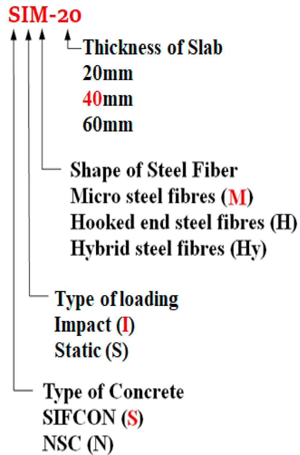
2.3. Samples Description

Twenty-four slab samples of SIFCON and 6 NSC slab reference samples were cast in the laboratory; the slabs are square with a side length of 900 mm and various thicknesses ranging from 20 to 60 mm, as shown in Table 2. Figure 1 and Figure 2 summarise the dimensions and coding of slab samples.

2.4. Samples Preparation

The chosen materials were weighed in accordance with the mix volume. Plywood moulds of 900 by 900 mm with varied thicknesses of 20, 40, and 60 mm have been utilised to cast the samples. The casting process is outlined below:
  • The plywood moulds were well cleaned and lubricated with oil on the inner faces to prevent adherence.
  • The technique of multi-layer casting is utilised to cast the SIFCON slabs. The mortars must flow properly to guarantee that the fibre is infiltrated. Then, full compaction and vibration were carried out using a vibrating table. For each layer, this process was repeated until the whole mould was filled with the desired thickness. Figure 3 shows the casting process of SIFCON and NSC slabs.
  • The moulded samples were covered with a polyethene sheet in a laboratory for 24 h after casting and finishing the top surface of all samples to prevent moisture evaporation from fresh concrete. After that, slab samples were cured for the desired age (between 7 and 56 days). The curing process was carried out by submerging the samples in clean water at room temperature (20 ± 2 °C).

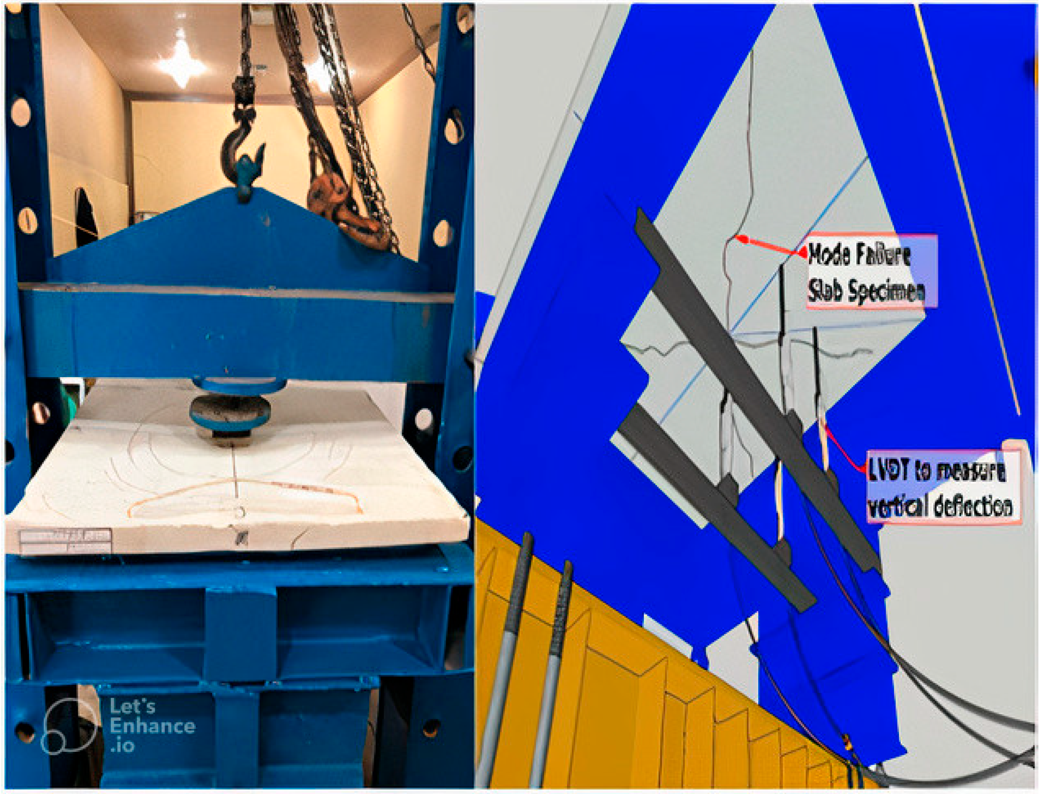
2.5. Test Set-Up and Instrumentation of SIFCON Specimens

Two days before testing, the slab specimens are removed from the immersed basins, cleaned, left to dry, and then coated with white emulation to facilitate the visualisation of crack spread. The static and impact tests were conducted on the same set-up to provide the perfect circumstances for the retained test slab samples. A specific support structure was produced and employed within the test methods. Six W-shape steel beams (W6 × 15, W10 × 22) were positioned and welded to form a square structure in this study. In addition, 25-mm-diameter steel bars welded on the top faces of steel beams provided simple support for the edge of the slab. The set-up remained the same for both experiments, but the loading practice was changed.
In both tests, the strain in the slab specimen assembly (NSC and SIFCON) was measured using internally and externally installed strain gauges. Four external strain gauges were bonded to the cleaned specimen surface (i.e., compression side) after pre-coating with a special adhesive to achieve a smooth surface. The installed strain gauges were then protected with layers of specialised silicon. Each of the four strain gauges had a length of 34 mm and a 6 × 40 mm base. Two internal strain gauges were installed on the steel reinforcement before the concrete was poured. Each strain gauge/reinforced steel bar joint was protected against moisture penetration during casting using a combination of urethane sealant, black plastic tape, and synthetic rubber adhesive. Three linear variable differential transducers (LVDTs) with additional steel extensions were placed on the ground to connect the bottom side of the slab (tension face) at different locations to measure vertical defection. A data collection system with an interface card-equipped computer was used to automatically acquire all test results (i.e., LVDT and strain gauges’ readings). An LVDT with a 50 mm maximum capacity was used in this study. In addition, the crack width meter was utilised to study the development of crack width with the applied force. The microscope accuracy was 0.05 mm. Data was recorded through contact with the load cells and LVDTs to a data logger of eight channels. Figure 4 shows the set-up of the slab testing method.

2.6. Static Load (Punching Shear) Test of the SIFCON Slabs

At the middle of the top surface of the testing samples, a concentrated load was applied using a loading neoprene slab of 300 mm × 500 mm on a 30-mm thick to prevent point load concentration. For each sample, the vertical deflections at the middle and the side of the bottom side of the slab were also measured using two LVDTs with a 50 mm stroke limit. In addition, a pressure gauge was utilised to measure the mid-span strain of the reinforcement. A calibrated electrohydraulic testing system with a maximum range of 2500 KN was used to test all the slab specimens for 90 days under increasing concentrated force until they failed. The strain gauges and the LVDTs were linked to a data-collecting system through a central control panel. The values of deflections, strains, and loads in the analogue electric signal have been transformed into digital signals and stored in computer files using the above measuring system. The load was gradually applied until failure occurred at a loading rate of 0.3 MPa/s. The initial cracking load and the ultimate load for each specimen with their deflections at different locations were documented. The used methods/procedures in this part of the study were adopted from the relevant literature [24,25,26,27].

2.7. Impact Loading Test of SIFCON Slab

This study employed a semi-spherical ball (hammerhead) made of high-strength steel to complete the impact loading test; this method was adopted from previous studies [28]. The hammerhead’s shape, weight, and drop height were kept constant during this research. A 100 × 100 × 10 mm steel slab in dimension is located on the samples at the contact point to avoid local fractures at the impact point and achieve popper load dispersion. Special polyurethane rubbers are also located between the loading slab and the sample. The slab was positioned in the testing set-up using a steel supporting configuration designed. A hammer of 84 kg was dropped from 1500 mm height on the middle of the slabs to test the impact resistance of the developed slabs, see Figure 5. By this, the impact load with identical input energy was applied to each slab equals 1.2361 kJ. An ICP piezoelectric dynamic load cell installed within a hemispheric component of the hammer in the testing set-up is used to measure an impact loading delivered to the testing specimen. Additionally, an accelerometer is connected to each specimen under the testing protocol to monitor vibration movements displayed by the specimens under impact loading. The vibration behaviours of the slabs attained by the accelerometers indicate the dynamic behaviour of the slabs subjected to impact loading. The test specimens were supplied with two piezoelectric accelerometers of 5000 g from a set distance from the impact point. These accelerometers are set in each direction at the crossing of the axes of test specimens. Due to the rapid loading of dynamic impact, a specific dynamic data logger (25 kHz at each channel, 25,000 figures/s) was used to record the data. The crack patterns were marked using a magic pencil at each load increment.

2.8. Numerical Modelling

Non-linear finite element analysis was carried out to simulate and analyse the failure of SIFCON slabs and compare it with the experimental results. The experimental data was modelled using the ABAQUS-2019 package.

2.8.1. Modelling and Analysis of Slab Specimens

The behaviour of the slabs was modelled using three dimensions solid parts. The NSC slabs were modelled as three parts (concrete, main reinforcement, and transfer reinforcement), while SIFCON slabs were modelled using one part. The finite element model was loaded at the exact locations in the experimental work.

2.8.2. Finite Element Mesh and Boundary Conditions

The level of complexity of the analysis and the time spent in the processing depends mainly on the mesh density. Therefore, a prior analysis of different densities of mesh was performed to determine the best mesh density that gives the required accuracy. To study the convergence, the number of elements was increased in all directions (X, Y, and Z). To model the behaviour of slabs; the samples were divided into coded elements, then elements with codes 891, 1400, 2300, 3484, 9500, and 80,600 were used in the modelling process. The software automatically selected these elements.
The axial displacements were measured for the same applied loads. Figure 6 shows that the changes in axial displacements are neglectable at mesh size between 10–5 mm. Therefore, an element size of 10 mm was used for the mesh density as this value guarantees a reasonable adjustment between the element’s size and the numerical solution’s stability.

2.8.3. Static and Impact Analysis Model

SIFCON and NSC slabs were modelled using three-dimensional solid elements with reduced integration in the modelling of the concrete with an 8-node brick element (C3D8R). For all slabs, a uniform pressure was applied at the top of the slab in which the bottom of the slab is fixed (displacement is restrained in all directions X, Y and Z-axis). While the top of the slab is restrained to displacement in the X and Z-axis, free displacement is assumed in the direction of the longitudinal axis of the slab (Y-axis), and a uniform loading was applied at the top of the slab, as manifested in Figure 7.

3. Results and Discussion

3.1. Experimental Results

3.1.1. Companion Specimen Test Results

The properties of the developed concrete investigated in this study include compressive and splitting tensile strength. The test results of the mechanical properties of the SIFCON are listed in Table 3. The results indicate that the compressive strength values of all SIFCON types are extensively higher than the standard concrete compressive strength, which is 25–50 MPa and 28–48 MPa according to the common engineering practice and ACI 318, respectively [29]. Additionally, the tensile strength of the SIFCON samples was higher than the average values for the standard concrete (ASTM C 496 suggested 3.1 MPa as the minimum tensile strength). It can be noticed that increasing the curing time from 7 to 28 and 56 days increased the compressive strength of micro steel, hybrid, and hooked end fibre samples by about 42%, 44%, and 52%, respectively. The elastic modulus and splitting tensile strength of micro steel, hybrid, and hooked end fibre samples also improved by 26%, 28%, and 27.5%, and 15.3%, 15%, and 13.7%, respectively.
The results above prove the positive effects of steel fibres on the mechanical properties of the SIFCON slabs. These results are agreed with those in the literature, such as the results of Naser and Abeer [30] and Khamees et al. [31].

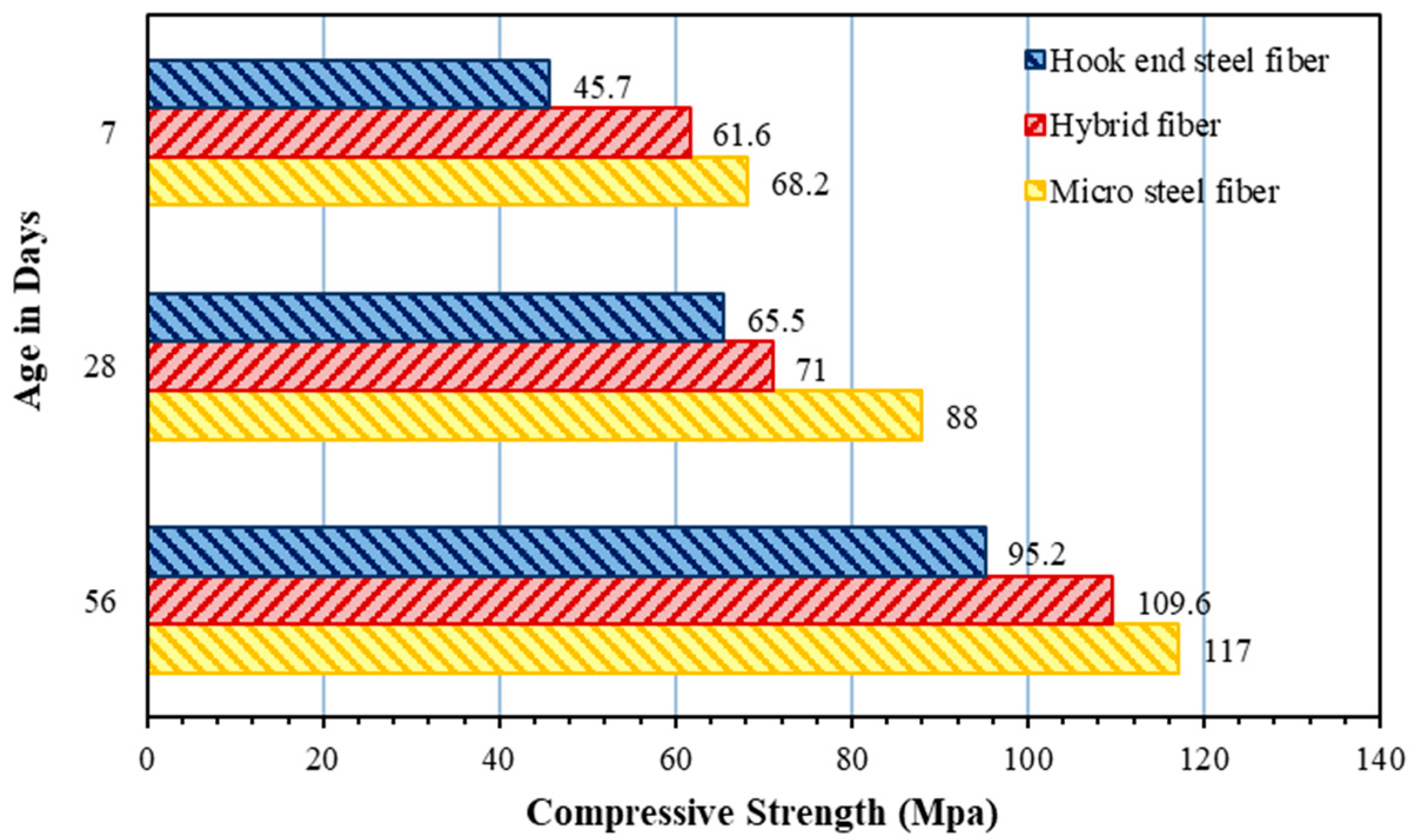
3.1.2. Compressive Strength

The compressive strength test is considered one of the most commonly used tests to evaluate the performance of hardened concrete, which is implemented to provide a proper estimation of the strength of a concrete member. Therefore, the compressive strength of the developed SIFCON samples was measured. This test was conducted using 100 × 100 × 100 mm cubes of SIFCON that were cured for 7, 28, and 56 days. The results of the compressive strength test are shown in Figure 8 and Table 3. The results prove the influence of the fibre shape on the development of the compressive strength of the SIFCON samples.
The results revealed that micro-steel fibre has a significantly higher compressive strength than other fibre types (hooked end and hybrid). The increase in the compressive strength of samples of micro steel fibre is attributed to the higher aspect ratio of micro steel fibre compared to other types of fibres; the micro fibres are shorter than other types and thereby occupy a smaller area in the concrete, which in turn results in a significant increase in the number of fibres used in the concrete [18]. The results also showed that the SIFCON samples with hybrid fibres have better compressive strength than those with hooked fibres. This is because the hooked ends and micro steel fibres have combined effects in bridging the concrete matrix and reducing the cracks’ development.
The results obtained from the compressive strength test agree with those in the literature [32]. Figure 9 compares the results of the present study and the literature (with the studies of Ali and Riyadh [18] and Sudarsana et al. [33].

3.1.3. Splitting Tensile Strength

The strength of the splitting tensile governs the cracking behaviour and influences other features, such as the durability and rigidity of the concrete. Therefore, the test was performed on SIFCON samples.
The results, as shown in Table 3, indicate that the splitting strength of the SIFCON generally rises with ageing. However, the cracks in the concrete can be easily spread under tensile load, which in turn significantly renders the tensile strength of the concrete far lower than its compressive strength. Generally, it can be noticed that increasing the curing time from 7 to 56 days increased the tensile strength of the SIFCON samples by 18.12%, 17.65%, and 15.87% for micro-steel, hybrid, and hooked-end fibres, respectively. Additionally, the results revealed that SIFCON’s tensile strengths are greater for those developed using micro steel fibres than those developed using other fibres. This increase may be attributed to the influence of the micro steel fibre’s high aspect ratio compared to the hooked ends that boost the tensile strength. Furthermore, this increase could be attributable to the fact that the connection and bridging of the fibres limit the development of microcracks [34,35,36]. The increasing tensile strength with time results from the hydration of the mixture by completing its internal microstructure, which leads to extra strength added to the composite material, together with an increase in the bond strength between the fibres and the matrix [37]. These results imply three significant conclusions: (1) the improvement in the tensile strength of SIFCON samples is not substantial compared to the increase in the compressive strength. (2) The relatively constant increment in tensile strength of SIFCON samples indicate the minimal contribution of slurry to tensile strength compared to the type of steel fibres. (3) The differences in the average tensile strength values are due to variations in steel fibre characteristics.
Figure 10 shows a comparison between the results of the current study and those in the literature, namely Deepesh and Jayant [38], Elavarasi [39], and Ali and Riyadh [18].

3.1.4. The Behaviour of SIFCON and NSC Slab under Impact Loads

The use of steel fibres in SIFCON slabs significantly improves their static and dynamic mechanical characteristics compared to conventional NSC slabs. This fact has been proved in this section of the study. It is noteworthy here to highlight that the results of impact loading are represented by the number of blows and displacement with time.
The results listed in Table 4 indicated that the SIFCON sample with hybrid steel fibres had the best mechanical properties; it resisted 1324 blows before showing failure signs, while the NSC sample resisted only 580 blows. Followed by the SIFCON samples with hook-end steel fibres at 1086 blows and SIFCON with micro steel fibres at 1075 blows. While the NSC samples showed the lowest resistance with a blows number of 580.
The effects of the thickness on the slab’s resistance to impact loads were investigated by subjecting SIFCON slabs (reinforced with hybrid steel fibres) with different thicknesses (20, 40, and 60 mm) to the impact load test. The results are shown in Figure 11, which clearly shows that increasing the thickness of the SIFCON slab significantly improves its ability to resist impact loads. It can be seen that increasing the thickness of the SIFCON slab from 2 to 4 and 6 cm increased the required number of blows to cause failure from 980 to 1168 and 1324, respectively. Figure 12 shows the failure patterns for the tested slabs (6 cm in thickness). This increase in improvement in the impact resistance of the slabs with the increase in the thickness of the slabs is attributed to the increase in the inertia of the slabs [40].

3.2. Finite Element Analysis Results

A comparison between the measured and numerical axial displacements of the tested NSC and SIFCON slabs is shown in Figure 13. The same figure shows the effect of slab thickness on load carrying capacity of SIFCON slabs with micro steel fibres for both experimental and finite element results. The micro steel fibres were used here because they provided the best mechanical properties of the SIFCON sample. The differences between the numerical and experimental results could be attributed to the difference in the assumption and reality; the finite element analysis considered that concrete is a homogenous material in all model directions. However, in reality, concrete is a heterogeneous material.
The results of these two figures highlight a number of important key facts: (1) the results of the numerical analysis highly agreed with the experimental results for the SIFCON samples with micro-steel fibres, which means the behaviour of the SIFCON slabs under static and impacts loads can be modelled using numerical methods. (2) Using micro-steel fibre to reinforce SIFCON plates gives a higher load-carrying capacity than the standard concrete. (3) The slab thickness significantly affects the load-carrying capacity, and it increases with increasing thickness. Finally, it can be noticed from the axial load-displacement relationships that all the numerical models show a stiffer behaviour when compared with the experimental axial load-displacement relationships. The most probable explanation for this disagreement is the presence of micro-cracks generated by drying shrinkage during the preparation of the slab samples; this will reduce the stiffness of these samples while these micro-cracks are not considered in the finite element model.
Figure 14 shows the crack pattern distribution at the bottom surface for SIFCON and NSC slab, with a thickness of 60 mm, under static load. The numerical result shows that the addition of fibres and type of fibres has a major effect on crack expansion, which agrees with the experimental observations. It can be seen from this figure that the stiffness of SIFCON slabs reinforced with micro steel fibre is the highest as it shows the smallest expansion of cracks, followed by the SIFCON slabs reinforced with hybrid fibres, then the SIFCON slabs with hooked end fibres. While the NSC slabs showed the lowest stiffness because the cracks are distributed on the whole cross-sectional area of the slab. These results are in good agreement with the experimental results, and the excellent resistance of the SIFCON slabs with micro steel fibres is attributed to (1) the connection and bridging of the fibres limit the development of microcracks and (2) the influence of the micro steel fibre’s high aspect ratio compared to other types of slabs that boost the tensile strength.

4. Conclusions

The current study focused on the experimental analysis of the behaviour of SIFCON slabs under different static and dynamic loading systems, the effects of the shape of steel fibres, and on modelling of the behaviour of these slabs using a non-linear finite element analysis. The outcomes of this study highlighted the following key facts:
  • SIFCON slabs have better mechanical properties than NSC slabs.
  • The use of micro- and hybrid steel fibres to reinforce SIFCON slabs gives a higher load-carrying capacity than hook-end steel fibres.
  • The slab thickness significantly affects the mechanical properties of the SIFCON mechanical properties, including the load-carrying capacity and impact load resistance.
  • The stiffness of SIFCON slabs reinforced with micro-steel fibre is higher than that of hooked-end and hybrid fibre slabs.
  • The non-linear finite element analysis is suitable for modelling of behaviours of SIFCON slabs under the studied loading systems (static and dynamic loads).
This article represents an initial step in modelling SIFCON slab behaviour under static and dynamic loads. Therefore, there is a future scope for more investigations; for example, more studies are required to model the effects of fire on the SICON slabs. Additionally, the behaviour of SIFCON slabs could be modelled using different modelling approaches, such as artificial neural networks (ANN), and comparing the results. Finally, the same investigation presented here could be re-conducted for longer time, up to one year), which would provide a better understanding of the behaviour of SIFCON slabs at after longer periods.

Author Contributions

Conceptualisation, M.H.Y., M.M.K. and W.G.B.A.-D.; methodology, M.H.Y., M.M.K. and W.G.B.A.-D.; software, W.G.B.A.-D.; validation, W.G.B.A.-D.; formal analysis, W.G.B.A.-D.; investigation, W.G.B.A.-D.; writing—original draft preparation, M.H.Y., M.M.K. and W.G.B.A.-D.; writing—review and editing, M.H.Y., M.M.K. and W.G.B.A.-D.; supervision, M.H.Y. and M.M.K. All authors have read and agreed to the published version of the manuscript.

Funding

This research received no external funding.

Data Availability Statement

Data should be requested from the authors.

Conflicts of Interest

The authors declare no conflict of interest.

References

  1. Kadhim, A.; Sadique, M.; Al-Mufti, R.; Hashim, K. Long-term performance of novel high-calcium one-part alkali-activated cement developed from thermally activated lime kiln dust. J. Build. Eng. 2020, 32, 101766. [Google Scholar] [CrossRef]
  2. Shubbar, A.A.; Sadique, M.; Nasr, M.S.; Al-Khafaji, Z.S.; Hashim, K.S. The impact of grinding time on properties of cement mortar incorporated high volume waste paper sludge ash. Karbala Int. J. Mod. Sci. 2020, 6, 7. [Google Scholar] [CrossRef]
  3. Khamees, S.S.; Kadhum, M.M.; Alwash, N.A. Experimental and numerical investigation on the axial behavior of solid and hollow SIFCON columns. SN Appl. Sci. 2020, 2, 1094. [Google Scholar] [CrossRef]
  4. Abbas, A.S.; Kadhum, M.M. Impact of fire on mechanical properties of slurry infiltrated fiber concrete (SIFCON). Civ. Eng. J. 2020, 6, 12–23. [Google Scholar] [CrossRef]
  5. Saatci, S.; Vecchio, F.J. Effects of shear mechanisms on impact behavior of reinforced concrete beams. ACI Struct. J. 2009, 106, 78–86. [Google Scholar]
  6. Majdi, H.S.; Shubbar, A.; Nasr, M.S.; Al-Khafaji, Z.S.; Jafer, H.; Abdulredha, M.; Masoodi, Z.A.; Sadique, M.; Hashim, K. Experimental data on compressive strength and ultrasonic pulse velocity properties of sustainable mortar made with high content of GGBFS and CKD combinations. Data Brief 2020, 31, 105961–105972. [Google Scholar] [CrossRef] [PubMed]
  7. Kadhim, A.; Sadique, M.; Al-Mufti, R.; Hashim, K. Developing one-part alkali-activated metakaolin/natural pozzolan binders using lime waste. Adv. Cem. Res. 2021, 33, 342–356. [Google Scholar] [CrossRef]
  8. Shubbar, A.A.; Sadique, M.; Shanbara, H.K.; Hashim, K. The Development of a New Low Carbon Binder for Construction as an Alternative to Cement. In Advances in Sustainable Construction Materials and Geotechnical Engineering, 1st ed.; Springer: Berlin/Heidelberg, Germany, 2020; pp. 205–213. [Google Scholar] [CrossRef]
  9. Vijayakumar, M.; Kumar, P.D. Study on strength properties of sifcon. Int. Res. J. Eng. Technol. (IRJET) 2017, 4, 235–238. [Google Scholar]
  10. Yazıcı, H.; Aydın, S.; Yiğiter, H.; Yardımcı, M.Y.; Alptuna, G. Improvement on SIFCON performance by fiber orientation and high-volume mineral admixtures. J. Mater. Civ. Eng. 2010, 22, 1093–1101. [Google Scholar] [CrossRef]
  11. Mohan, A.; Karthika, S.; Ajith, J.; Tholkapiyan, M. Investigation on ultra high strength slurry infiltrated multiscale fibre reinforced concrete. Mater. Today Proc. 2020, 22, 904–911. [Google Scholar] [CrossRef]
  12. Ali, M.H.; Atiş, C.D.; Al-Kamaki, Y.S.S. Mechanical properties and efficiency of SIFCON samples at elevated temperature cured with standard and accelerated method. Case Stud. Constr. Mater. 2022, 17, e01281. [Google Scholar] [CrossRef]
  13. Murali, G.; Abid, S.R.; Al-Lami, K.; Vatin, N.I.; Dixit, S.; Fediuk, R. Pure and mixed-mode (I/III) fracture toughness of preplaced aggregate fibrous concrete and slurry infiltrated fibre concrete and hybrid combination comprising nano carbon tubes. Constr. Build. Mater. 2023, 362, 129696. [Google Scholar] [CrossRef]
  14. Soylu, N.; Bingöl, A.F. Research on effect of the quantity and aspect ratio of steel fibers on compressive and flexural strength of SIFCON. Chall. J. Struct. Mech. 2019, 5, 29. [Google Scholar]
  15. Aygörmez, Y.; Al-mashhadani, M.M.; Canpolat, O. High-temperature effects on white cement-based slurry infiltrated fiber concrete with metakaolin and fly ash additive. Rev. Construcción 2020, 19, 324–333. [Google Scholar] [CrossRef]
  16. Kanagavel, R.; Kalidass, A. Mechanical properties of hybrid fibre reinforced quaternary concrete. Građevinar 2017, 69, 175530. [Google Scholar]
  17. Pradeep, T.; Sharmila, S. Cyclic behavior of RC beams using SIFCON sections. Int. J. Innov. Res. Sci. Eng. Technol. 2015, 4, 1–10. [Google Scholar]
  18. Ali, A.S.; Riyadh, Z. Experimental and Numerical Study on the Effects of Size and type of Steel Fibers on the (SIFCON) Concrete Specimens. Int. J. Appl. Eng. Res. 2018, 13, 1344–1353. [Google Scholar]
  19. Khamees, S.S.; Kadhum, M.M.; Alwash, N.A. Effect of hollow ratio and cross-section shape on the behavior of hollow SIFCON columns. J. King Saud Univ.-Eng. Sci. 2021, 33, 166–175. [Google Scholar] [CrossRef]
  20. Jerry, A.H.; Fawzi, N.M. The effect of using different fibres on the impact-resistance of slurry infiltrated fibrous concrete (SIFCON). J. Mech. Behav. Mater. 2022, 31, 135–142. [Google Scholar] [CrossRef]
  21. Akçaözoğlu, K.; Kıllı, A. The effect of curing conditions on the mechanical properties of SIFCON. Rev. Constr. 2021, 20, 37–51. [Google Scholar]
  22. Rao, H.S.; Ghorpade, V.G.; Ramana, N.; Gnaneswar, K. Response of SIFCON two-way slabs under impact loading. Int. J. Impact Eng. 2010, 37, 452–458. [Google Scholar] [CrossRef]
  23. Al-Obaidi, Z.A.-J.A. The Effect of Using Recycled Aggregates on Some Mechanical and Impact Properties of Concrete Slabs Reinforced with Plastic Waste Fibers; EasyChair: Manchester, UK, 2020; pp. 2314–2516. [Google Scholar]
  24. Drdlová, M.; Sviták, O.; Prachař, V. Slurry infiltrated fibre concrete with waste steel fibres from tires-the behaviour under static and dynamic load. In Proceedings of the Materials Science Forum, Tokyo, Japan, 9–11 June 2017; pp. 76–82. [Google Scholar]
  25. Azoom, K.; Pannem, R.M.R. Punching strength and impact resistance study of sifcon with different fibres. Int. J. Civ. Eng. Technol. 2017, 8, 1123–1131. [Google Scholar]
  26. Rao, H.S.; Ramana, N.; Gnaneswar, K. Behaviour of steel reinforced slurry infiltrated fibrous concrete (SIFCON) two way slabs in punching shear. Indian J. Eng. Mater. Sci. 2008, 15, 334–342. [Google Scholar]
  27. Rao, H.S.; Ramana, N. Behaviour of slurry infiltrated fibrous concrete (SIFCON) simply supported two-way slabs in flexure. Indian J. Eng. Mater. Sci. 2005, 12, 427–433. [Google Scholar]
  28. Yılmaz, T.; Kıraç, N.; Anil, Ö.; Erdem, R.T.; Sezer, C. Low-velocity impact behaviour of two way RC slab strengthening with CFRP strips. Constr. Build. Mater. 2018, 186, 1046–1063. [Google Scholar] [CrossRef]
  29. Vu, C.-C.; Ho, N.-K.; Pham, T.-A. Weibull statistical analysis and experimental investigation of size effects on the compressive strength of concrete-building materials. Case Stud. Constr. Mater. 2022, 17, e01231. [Google Scholar] [CrossRef]
  30. Naser, F.H.; Abeer, S. Flexural behaviour of modified weight SIFCON using combination of different types of fibres. In Proceedings of the IOP Conference Series: Materials Science and Engineering, Chennai, India, 5–6 October 2020; p. 012178. [Google Scholar]
  31. Khamees, S.S.; Kadhum, M.M.; Nameer, A.A. Effects of steel fibers geometry on the mechanical properties of SIFCON concrete. Civ. Eng. J. 2020, 6, 21–33. [Google Scholar] [CrossRef]
  32. Qian, C.; Stroeven, P. Development of hybrid polypropylene-steel fibre-reinforced concrete. Cem. Concr. Res. 2000, 30, 63–69. [Google Scholar] [CrossRef]
  33. Sudarsana, R.H.; Ramana, N.; Gnaneswar, K. Behaviour of restrained SIFCON two way slabs part 1: Flexure. Asian J. Civ. Eng. (Build. Hous.) 2005, 10, 427–449. [Google Scholar]
  34. Labib, M.; Moslehy, Y.; Ayoub, A. Softening coefficient of reinforced concrete elements subjected to three-dimensional loads. Mag. Concr. Res. 2018, 70, 11–27. [Google Scholar] [CrossRef]
  35. Ipek, M.; Aksu, M. The effect of different types of fiber on flexure strength and fracture toughness in SIFCON. Constr. Build. Mater. 2019, 214, 207–218. [Google Scholar] [CrossRef]
  36. Tuyan, M.; Yazıcı, H. Pull-out behavior of single steel fiber from SIFCON matrix. Constr. Build. Mater. 2012, 35, 571–577. [Google Scholar] [CrossRef]
  37. Agha, A.A.; Kadhum, M.M. Behavior of Reactive Powder Concrete Columns under Axial Compression. Master’s Thesis, Babylon University, Babylon, Irak, 2015; pp. 571–577. [Google Scholar]
  38. Deepesh, P.; Jayant, K. Study of mechanical and durability properties of SIFCON by partial replacement of cement with fly ash as defined by an experimental based approach. Int. J. Innov. Res. Sci. Technol. 2016, 5, 8568–8574. [Google Scholar]
  39. Elavarasi, M.; Saravana Raja Mohan, K. Performance of Slurry Infiltrated Fibrous Concrete (Sifcon) with Silica Fume. Int. J. Chem. Sci. 2016, 14, 2710–2722. [Google Scholar]
  40. Ožbolt, J.; Riedel, W. Modelling the response of concrete structures from strain rate effects to shock induced loading. In Understanding the Tensile Properties of Concrete; Elsevier: Amsterdam, The Netherlands, 2013; pp. 295–340e. [Google Scholar]
Figure 1. Samples coding method adopted in this research.
Infrastructures 08 00019 g001
Figure 2. Details of SIFCON slab specimens.
Infrastructures 08 00019 g002
Figure 3. The casting of SIFCON and NSC slabs.
Infrastructures 08 00019 g003
Figure 4. The set-up of the slab testing method.
Infrastructures 08 00019 g004
Figure 5. The set-up of the impact load test.
Infrastructures 08 00019 g005
Figure 6. The change in axial displacement.
Infrastructures 08 00019 g006
Figure 7. The boundary conditions and finite element idealisation of steel reinforcement of both SIFCON and NSC slab specimens.
Infrastructures 08 00019 g007
Figure 8. The compressive strength of the SIFCON using various types of fibres.
Infrastructures 08 00019 g008
Figure 9. Comparison between the SIFCON compressive strength and the literature at 28 days.
Infrastructures 08 00019 g009
Figure 10. Comparison between the tensile strength of SIFCON and the literature at 28 days.
Infrastructures 08 00019 g010
Figure 11. The relationship between the number of blows to slab failure and thickness of SIFCON slabs with hybrid steel fibres.
Infrastructures 08 00019 g011
Figure 12. Failure patterns of (A) SIFCON slab with hybrid steel fibres, (B) SIFCON slab with hook-end steel fibres, (C) SIFCON slab with micro steel fibres, and (D) NSC slabs from the bottom under impact loading.
Infrastructures 08 00019 g012
Figure 13. Experimental and numerical load-axial displacement relationship of (A) NSC (thickness = 60 mm), (B) SIFCON slabs with micro steel fibre (thickness = 60 mm), and (C) SIFCON slabs with micro steel fibre (thickness = 20 mm).
Infrastructures 08 00019 g013
Figure 14. Crack pattern distribution for: (A) NSC slabs, (B) SIFCON slab with micro steel fibres, (C) SIFCON slab with hook end fibres, and (D) SIFCON slab with hybrid steel fibres.
Infrastructures 08 00019 g014aInfrastructures 08 00019 g014b
Table 1. Mixing proportion of SIFCON and normal strength concrete.
Mix TypeMix Proportion
Cement (Kg/m3)Sand
(Kg/m3)
SF Kg/m3 10% rep.Gravel
(Kg/m3)
Fibres%w/b
Ratio
SP% (wt. of Binder)
SIFCON872.196996.9-60.333.7
NSC518763-768-0.44-
Table 2. Summary of SIFCON slab test specimens.
Type of SlabType of LoadingType of FibreSlab SymbolSlab Thickness (mm)
SIFCON SlabStaticMicro-steel
fibre
SSM-2020
SSM-4040
SSM-6060
Hybrid fibre SSH-2020
SSH-4040
SSH-6060
Hook-end steel fibreSSH-2020
SSH-4040
SSH-6060
ImpactMicro-steel
fibre
SIM-2020
SIM-4040
SIM-6060
Hybrid fibreSIHy-2020
SIHy-4040
SIHy-6060
Hook-end steel fibreSIH-2020
SIH-4040
SIH-6060
Normal Concrete SlabsStatic-NS-6060
ImpactNS-6060
Table 3. Summary of the mechanical properties of the SIFCON.
The Shape of Steel Fibre (6% Vf)Compressive Strength (MPa)Elastic Modulus (GPa)Splitting Tensile Strength (MPa)
7 Days28 Days56 Days7 Days28 Days56 Days7 Days28 Days56 Days
Micro steel68.28811723.328.631.617.119.320.2
Hybrid fibre61.671109.621.726.83015.317.218
Hook-end fibre45.765.595.219.625.42712.614.114.6
Table 4. Summary of impact loading carrying capacity of SIFCON and NSC slabs with a thickness of 6 cm.
Sample TypeNo. of Blows at Failure
SIFCON with hybrid steel fibres1324
SIFCON with micro-steel fibres1075
SIFCON with hook-end steel fibres1086
NSC580
Disclaimer/Publisher’s Note: The statements, opinions and data contained in all publications are solely those of the individual author(s) and contributor(s) and not of MDPI and/or the editor(s). MDPI and/or the editor(s) disclaim responsibility for any injury to people or property resulting from any ideas, methods, instructions or products referred to in the content.

