Article

Evaluating the Performance of Lateritic Soil Stabilized with Cement and Biomass Bottom Ash for Use as Pavement Materials

Department of Civil Engineering, Rajamangala University of Technology Srivijaya, Songkhla 90000, Thailand
*
Author to whom correspondence should be addressed.
Infrastructures 2022, 7(5), 66; https://doi.org/10.3390/infrastructures7050066
Submission received: 9 April 2022 / Revised: 26 April 2022 / Accepted: 26 April 2022 / Published: 29 April 2022

Abstract

:
From the perspective of sustainable waste management and its environmental impact, waste biomass bottom ash (BA) remains problematic and challenging to use as a recycling material for civil engineering infrastructures. This study evaluated the performance of lateritic soil (LS), stabilized with cement and biomass BA, as a subbase material. BA has been considered a replacement material in LS prior to the introduction of hydraulic cement stabilization means. The geotechnical engineering tests comprised the modified Proctor test, the California Bearing Ratio (CBR) test, and the unconfined compression test. X-ray fluorescence (XRF) and X-ray diffraction (XRD) tests were conducted to investigate the mineralogical properties of the stabilized soil samples. The leachate test was performed with a permeability mold to measure the release of heavy metals. Finally, the benefits of using the stabilized subbase material were assessed using the mechanistic–empirical (M–E) pavement design approach. Based on the results obtained, the strength and stiffness characteristics of the stabilized soils indicate that the efficiency of the mix satisfied the Thailand highway specification. The admixture of 80% BA and 5% cement is suggested for use as a soil–cement subbase material for flexible pavements, due to its good engineering and environmental properties. The results of the M–E design demonstrate the effectiveness of the stabilized soil presented herein. The study’s outcomes are predicted to promote the utilization of waste BA as a promising pavement material.

1. Introduction

Transportation infrastructure has increasing demands due to the increasing population, and rapid growth of the economy, society, and industry. Thailand has a long-term plan for the development of the overall transportation infrastructure, especially road transportation, which is the most popular means of transport in Thailand [1]. Lateritic soil (LS) is generally used as road material—for example, in subbase layers in Thailand, and in other tropical regions (Malaysia, Brazil, Nigeria, etc.). However, the majority of the remaining tropical lateritic soil contains a large percentage of fine-grained soil particles, resulting in poor engineering properties. Moreover, it is well known that the engineering characteristics of weathered lateritic soil from different sources differ depending on their chemical and physical processing. As a result, approaches to improve the characteristics of certain types of soils as road materials are required [2].
Soils in tropical and arid areas are always unsaturated due to climatic conditions. The key feature of the unsaturated zone is the negative pore-water pressure or suction, which varies with soil moisture content. As a result of variable moisture content, soil properties are relatively constant in the saturated zone but vary spatially and temporally in the unsaturated zone. In general, ignoring unsaturated effects increases the safety of the geo-structure design. The suction profile beneath a covered ground surface is more constant over time than the profile beneath an uncovered surface. However, moisture may slowly accumulate below the covered area over time, causing a reduction in soil suction. As the flexible pavement is covered by an asphalt concrete layer, it helps to prevent water infiltration into the pavement structure. In this case, the soil suction profile remains relatively constant throughout the dry and wet seasons [3]. Therefore, the effects of unsaturated soils on the strength characteristics and performance were unconsidered in this study.
Waste industrial recycling and management is still a broad concern in civil engineering works to help to reduce the impacts of environmental hazards caused by waste disposal (plastic, rubber tire, fly ash, bottom ash, etc.). The focus of this paper is biomass bottom ash. Biomass ashes (i.e., fly ash and bottom ash) are by-products of biomass combustion, which is considered a clean energy source with no CO2 emissions [4]. This industrial waste ash is highly recyclable, resulting in economic and environmental benefits. Bottom ash, which has higher strength and less heavy metal leaching than fly ash, can be used in all highway material layers [5]. The positive results of this waste ash utilization in road construction applications can be found in numerous previous works. For instance, López et al. [6] characterized two types of silica–aluminous bottom ashes in Spain, and suggested that soils can be improved by incorporating bottom ash contents ranging from 15 to 40% of the soil’s weight, thereby increasing their load-bearing capacity while decreasing their plasticity. Cabrera et al. [7] investigated the feasibility of using biomass bottom ash (BA) across three different power plants in Spain’s civil infrastructure environment, based on their physicochemical properties. They suggested that restricting the level of organic matter in the BA would allow it to be used as a filler material for embankments and a broader range of civil infrastructures.
Regarding with leaching of some heavy metals in the biomass ashes, pretreatment methods (separation, solidification/stabilization (S/S), heat treatment, etc.) are required [5]. Chemically treated soils are a common technique in road construction, alongside typical additives, such as fly ash, cement, and lime. Cement-based stabilization techniques are widely used as stabilized materials in pavement structure layers, for instance, in the study by [8,9,10,11]. The use of incinerator bottom ash (IBA) as cement-bound material for use as road material in the UK was reported by Paine et al. [8]. The authors suggested that the IBA can be practically used in proportions of 40% or more by mass of aggregate with a cement content of about 2–8%, which met the compressive strength of UK highway specifications and is well within typical regulatory drinking limits. Jaritngam et al. [9] concluded that approximately 3% Portland cement is sufficient to stabilize lateritic soil for use as a road base material that meets Thailand Department of Highways (DOH) specifications and can be a cost-effective substitute for crushed rock. While Donrak et al. [11] reported that using 5% cement-stabilized lateritic soil and melamine debris blends as subbase materials can be used safely in sustainable pavement applications.
A mechanical and durability investigation of cement-treated lateritic soil in Malaysia was carried out by Wahab et al. [12]. The study results indicated that the strength development of 9 and 12% cement-treated lateritic specimens showed an increasing trend against wet-dry cycles, which led to long-term pozzolanic reactions. The leaching potential of the material usually has been determining the acceptance criteria for reusing bottom ash in road applications, in both laboratory (e.g., [8,13]) and field performance (e.g., [14,15,16]) investigations. Del Valle-Zermeno et al. [17] built a pilot-scale road subbase made with granular material stabilized with bottom ash and cement mortar in Spain. The results revealed that the pozzolanic effect of the cement mortar is responsible for the immobilization of all heavy metals. Cabrera et al. [18] investigated the leaching behavior of 5% cement-treated recycled aggregate and BA mixtures using a standard column test. They claimed that the use of BA in road construction had no negative effects on the environment.
Numerous researchers have performed laboratory testing of chemically treated soils, followed by performance analysis using numerical modeling, to assess the feasible use of waste materials due to the limitation of full-scale tests of roads. The basic idea behind using mechanistic modeling techniques for pavement design is to choose the thickness of the pavement structure which will limit the vertical compressive strains at the top of the subgrade, and the horizontal tensile strains at the bottom of the asphalt surface caused by traffic loads [19]. Lekha et al. [20] reported on the strength and durability improvements in lateritic soil stabilization with 1% Arecanut coir and 3% cement. They found that the stress and displacement of the pavement structure were reduced by 6–10% and 4–18% respectively, when using the KENLAYER (The University of Kentucky, Lexington, KY, USA) computer program. Stabilizing fly ash and lime sludge mixed with lime and gypsum for use as a road construction material was explored by Sahu et al. [21]. The three-layered flexible pavement was built using the finite element code PLAXIS 2D, including a reliability index for rutting and fatigue failure of the pavement. The authors suggested that the study outcome is useful for assessing the performance of the pavement concerning rutting and fatigue failure under a given environment. Anaokar and Mhaiskar [22] investigated the effectiveness of a C-shaped lime-stabilized capping beneath an embankment carrying flexible pavement on an expansive subgrade. PLAXIS 3D (Bentley Systems, Exton, PA, USA) was used to investigate load displacement behaviors. The authors concluded that lime-stabilized capping, consisting of a horizontal buffer layer and vertical cut-offs, was effective at controlling swelling displacements in expansive subgrades. Other studies also used mechanistic modeling techniques; for example, the finite element method PLAXIS 2D to investigate the displacement behavior of the coal gangue embankment in China [23], and KENLEYER software to evaluate the performance of using cement-stabilized soil for the flexible pavement in China [24] and the USA [25,26,27]. These studies have shown the effectiveness of using the M–E method in pavement design, providing important results for the assessment of the proposed materials.
Ordinary Portland cement (OPC) is a traditional cementitious material for road applications with a cement content of 2 to 10% (e.g., [9,11,12,28]). However, cement production accounts for approximately 5–8% of total anthropogenic CO2 emissions, owing primarily to the conversion of CaCO3 into CaO, and the combustion of fossil fuels during the mixing of raw materials during heating [29,30]. Many efforts have been made to reduce these emissions, including the use of alternative cementitious materials such as blast furnace slags and fly ash from coal combustion in the place of traditional Portland cement [29]. Hydraulic cement (HC) is an inorganic material that, when mixed with water, hardens and becomes water-resistant [30]. HC consists of about 10% clinker-replacement materials (calcium carbonate, limestone, fly ash, natural pozzolan, etc.). In the studies mentioned, none utilized environment-friendly cementitious materials such as HC for road pavement applications. Furthermore, biomass waste is widely used as a biofuel for power generation in Thailand. The seven biomass combustion plants provide approximately 60 MW of electrical energy capacity (23,000 toes) to the Songkhla Province, which is regarded as the economic center in the lower part of southern Thailand. A report by the Songkhla Provincial Industry, there are issues with waste ash management due to large amounts of biomass ash (i.e., fly ash and bottom ash), which makes it difficult to develop the industrial area into an eco-industrial town [31].
Therefore, this study evaluates the feasibility and performance of utilizing local LS mixed with BA and HC mixtures as soil–cement subbase materials. Three main tasks were carried out—namely: (1) geotechnical engineering tests to analyze the strength development; (2) laboratory leaching tests for the estimation of potential heavy metal release; (3) pavement design and analysis of the pavement’s life using the mechanistic–empirical approach. Based on the results obtained, the feasibility of BA in civil infrastructures is then presented. Additionally, the work presented in this paper could contribute substantially to the reduction of greenhouse gas emissions from cement production. The replacement of biomass ash in the soil–cement subbase would result in additional benefits toward reducing the consumption of energy and raw materials in the cement industry, besides also reducing the direct impact of landfills associated with biomass combustion residues.

2. Materials and Methods

2.1. Materials

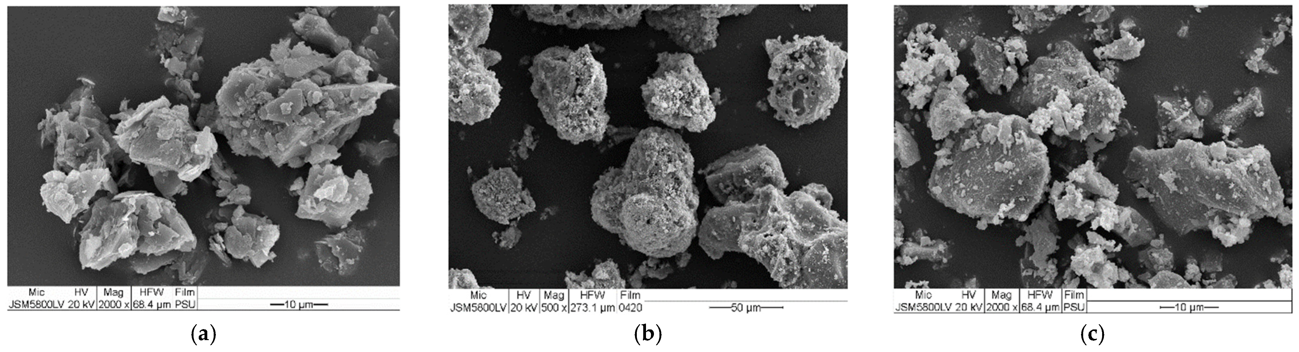
2.1.1. Lateritic Soil

Samples of lateritic soil (LS) used in this study were collected from the local borrow pit site of the Hat Yai Sub-district, Songkhla Province. The LS sample was tested to define its physical properties, which comprised wet sieve analysis, specific gravity, and Atterberg’s limit tests. The results of the soil characterization tests are summarized in Table 1. As observed in Table 1, the LS consisted of 32% gravel, 21% sand, and 47% fine-grained soil. The particle size distribution of the soil is shown in Figure 1. The median particle size (D50) of soil was 0.15 mm, and the specific gravity was 2.755. The soil consistency parameters were 30, 21, and 9% for the liquid limit (LL), plastic limit (PL), and plasticity index (PI), respectively. According to the Unified Soil Classification System (USCS), the lateritic soil sample was classified as reddish–yellow clayey gravel with sand (GC). The LS had a wearing resistance value of more than 60% based on the Los Angeles abrasion test, which did not meet the subbase specification of the Department of Highways (DOH) of Thailand [32].
The chemical composition of the LS from the X-ray fluorescence (XRF) test is presented in Table 2. The dominant compounds in the soil were silicon dioxide (59.79%), aluminum oxide (20.59%), and ferric oxide (8.07%). The total amount of major components of 88.44% can be considered as high for the necessary pozzolanic reaction [33]. Additionally, the LS in the present study had a weathering index of more than 2.0, which identified it as fersiallitic tropical soil based on the silica to sesquioxide ratio [34]. The scanning electron microscopy (SEM) image in Figure 2a shows small particles in clusters patterns.

2.1.2. Biomass Bottom Ash

In this study, the biomass bottom ash (BA) was a by-product of the Para rubber wood combustion from manufacturers of the wood substitute products, which was obtained from Panel Plus Co., Ltd., situated in the Hat Yai Sub-district, in Songkhla Province. The physical and chemical properties of the BA are shown in Table 1 and Table 2, respectively. As seen in Table 1, BA has a specific gravity is 2.405, and the D50 was 1.60 mm. BA is a non-plastic material and is classified as a poorly graded sand (SP) according to the USCS method. The grain size distribution curve of the BA is depicted in Figure 1. The morphology of the BA in Figure 2b is that of relatively porous particles and rough textures. The XRF analysis (Table 2) showed three major components (SiO2, Al2O3, and Fe2O3) which made up 75.62% of the BA, which is more than 70%. Therefore, the BA could be classified as a pozzolanic material Class F based on the ASTM C618 standard [35].

2.1.3. Hydraulic Cement

The Hydraulic Cement (HC) used in this study was from INSEE Petch Plus, which is a general use (GU) type according to the Thailand Industrial Standard (TIS 2594-2013) [36]. The chemical composition (Table 2) revealed the presence of calcium oxide (CaO), which was approximately 65%, and acted as the dominant mineral in the HC. The SEM image (Figure 2c) depicts irregular shapes with sharp corners.

2.2. Sample Preparation and Testing

In this study, the specimen was categorized into two groups, namely, uncemented and cement-stabilized soil (CSS) specimens. The LS was partially replaced with BA at proportions of 0, 40, 60, 80, and 100%. For the CSS specimen, the HC contents of 3, 5, and 7% by weight of the dry soil aggregate (LS + BA) were mixed with a soil aggregate sample. Gradation analysis of the LS blended BA (Figure 1) met the criteria set by the DOH. In Figure 1, the letters S and B refer to amounts of lateritic samples of soil and bottom ash, respectively. For example, S60B40 denotes the mix with 60% LS + 40% BA. Laboratory tests, including compaction tests, the California bearing ratio (CBR) test, and the unconfined compression (UC) test, were conducted to determine the geotechnical characteristics of the mixtures. The details of the testing program are summarized in Table 3.

2.2.1. Compaction and CBR Tests

The modified Proctor test according to ASTM D 1557 [37] was performed to determine the maximum dry unit weight (γdmax) and optimum moisture content (OMC) for both the uncemented and CSS specimens. In this study, the soaked CBR test according to ASTM D 1883 [38] was conducted only on the uncemented specimen to determine the CBR value for evaluating it as a civil infrastructure material.

2.2.2. Unconfined Compression (UC) Test

The UC test was performed for the CSS specimens according to the specification of the Department of Highways (DOH) of Thailand [32]. The LS and BA samples were passed through a 4.75 mm sieve, and then dried in an oven for 24 h before blending with the HC. They were then mixed with water at an OMC obtained from the compaction test. For each mixture, three replicate specimens were prepared with a diameter of 50.2 mm and a height of 102 mm. Then they were compacted in the cylindrical split mold via a ram of 4.50 kg, with a 200 mm drop length across three layers (21 blows/layer). Each layer reached the specified modified Proctor energy values. After the molding process, the stabilized specimen was carefully extracted from the mold and then wrapped in a plastic bag. It was stored in a humidity chamber at a constant temperature (25 ± 2 °C). After achieving the specified curing time, the CSS specimens were soaked in water for 2 h, and then the compression test with a compression machine under the constant loading rate with fixed a vertical displacement of 1 mm/min was carried out [32]. The UC tests were conducted for three specimens, and an average value was reported. The secant Young’s modulus (E50) was determined from the UC tests to analyze the stiffness of the mix.

2.2.3. Leachate Test

The major concern when stabilizing industrial waste materials (i.e., fly ash, bottom ash) is the leachate’s characteristics [13]. Bottom ash contains some harmful chemicals, including heavy metals, which are rapidly leachable. In this study, both uncemented and CSS mixes were compacted in the permeability mold and then kept for curing in a humidity chamber at 25 ± 2 °C for 7 days. The water outflow from the permeability mold was collected in sampling bottles for leachate analysis.

2.3. Pavement Design

The mechanistic–empirical (M–E) design method is based on material mechanics and relates to an input, such as wheel load, and an output or pavement response, such as stress or strain. Laboratory tests and field performance data are used to predict distress using these response values. As theory alone does not prove sufficient for designing realistic pavements, reliance on the observed performance was required [39]. In this study, stress-strain analysis was performed using the KENLAYER computer program, which is based on the multi-layer elastic theory. The design procedure and input parameters for this analysis are illustrated as follows.
(i)
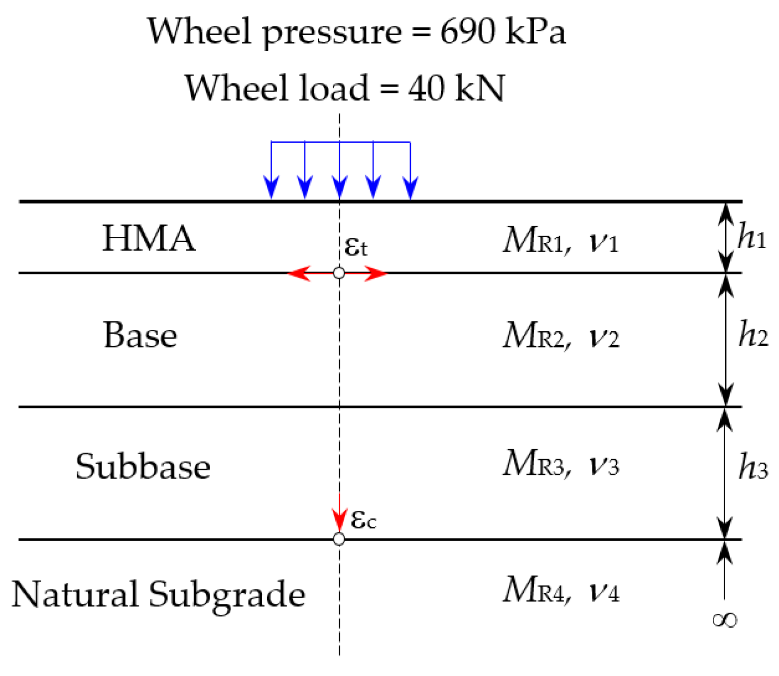
Assigning the number of layers and the thickness of each layer based on the Thailand DOH. The four-layer systems (Figure 3) consisted of a hot mix asphalt (HMA) surface course, base course, subbase course, and natural subgrade.
(ii)
Assigning the traffic load condition of a single axle with a dual tire, standard axle load (80 kN), and contact pressure of 690 kPa.
(iii)
Pavement materials assumed linear elastic behavior for all layers. The Poisson’s ratio (ν) and resilient modulus (MR) were varied depending on specific layers. Determination of the MR values for the stabilized subbase material used the empirical correlation of the unconfined compressive strengths (qu) obtained from this experiment’s tests.
(iv)
The pavement response analysis to evaluate the benefits of using the CSS as road pavement materials were documented.
The resilient modulus (MR) value, which characterizes the mechanical responses of pavement materials, is required as an input parameter in pavement structural design. The MR test, on the other hand, typically necessitates a significant amount of time and expertise to be carried out correctly [40]. As a result, each test can be costly, and can add significantly to the cost of a highway project. AASHTO [41] recognized the practical issues associated with determining MR and offers a three-level hierarchical approach: laboratory measurement, empirical correlation with soil properties, and the use of a default value based on soil types for levels 1, 2, and 3, respectively. According to the literature, the qu value for stabilized soil can be used to predict the MR, and this method was used in this study. The MR equations for each materials layers are illustrated in the following equations:
(a)
For untreated soil
-
For fine-grained soils with CBR less than or equal to 10% [42]
MR = 10CBR
-
For CBR > 10% [43]
MR = 17.6CBR0.64
(b)
For treated soil [44]
MR = 149qu
(c)
For HMA, the MR value presented by Saglik and Gungor [45], which is a simplified Witczak’s dynamic modulus equation, was adopted. The experimental results from the study of Lukjan et al., 2022 [46] were used for assessing the MR values of the hot mix asphalt concrete (HMA) pavement:
MR = 3.75 + 0.029P200 − 0.00177[P200]2 − 0.0028R4 − 0.058Va − 0.8[Vb/(Vb + Va)] + [A/B]
A = 3.87 − 0.0021R4 + 0.004R3/8 − 1.7 × 10⁻⁵ [R3/8]2 + 0.0055R3/4
B = 1 + e 2.56 + 0.89 log ( p e n )     0.0015 [ log ( p e n ) ] 2
where MR = resilient modulus (kPa), qu = unconfined compressive strength (kPa), Va = air void (%),Vb = effective asphalt content (%), P200 = passing No.200 sieve (%), R4 = retained No.4 sieve (%), R3/8 = retained No.3/8 sieve (%), R3/4 = retained No.3/4 sieve (%), and pen = penetration of asphalt cement.

2.4. Performance Analysis

The failure patterns of the flexible pavement system generally consist of fatigue cracking and rutting deformation. Fatigue cracking is due to the excessive horizontal tensile strain (εt) at the bottom of the surface course, while the occurrence of vertical compressive strain (εc) at the top of the subgrade layer causes the rutting deformation. A mechanistic–empirical pavement design, known as a transfer function, was performed in this study to evaluate the overall performance of the pavement [39]. Fatigue and rutting models of the pavement were adopted to evaluate the benefits of the CSS in terms of its traffic benefits ratio (TBR). The TBR values were defined through the extension in the service life of the pavement system [47] when the CSS was used as the subbase course material.
To predict the life of the pavement, the number of allowable loads before the pavement structure’s failure occurs must be determined. For the fatigue model, the desired equation of the Minnesota Department of Transportation [48] was adopted to calculate the allowable number of load repetitions (Nf):
Nf = 2.83 × 10⁻⁶t)−3.21
For the rutting model, the allowable numbers of load repetitions (Nr) to produce a rut depth less than 10.2 mm presented by the Transport and Road Research Laboratory (TRRL) [43] with a reliability of 85% was adopted:
Nr = 6.18 × 10⁻⁸c)−3.95
Thus, the TBR values can be calculated using Equations (9) and (10):
TBRf = (εtuts)−3.21
TBRr = (εcucs)−3.95
where TBRf and TBRr are the traffic benefit ratios corresponding to the Nf and Nr values, respectively; u and s denote unstabilized and stabilized subbase course, respectively.

3. Results

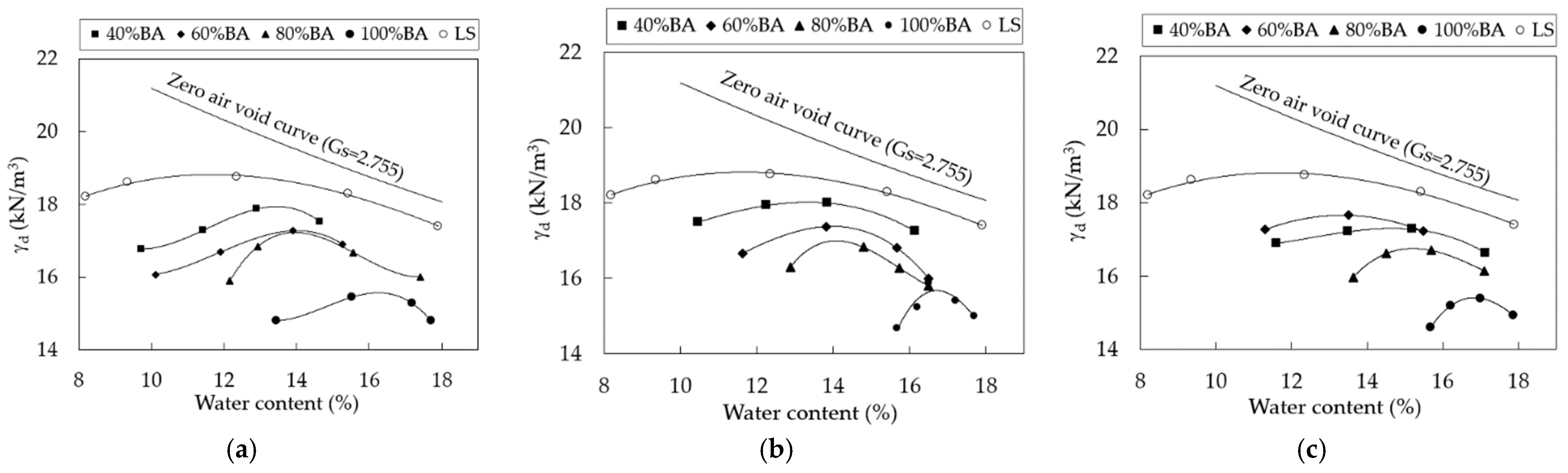
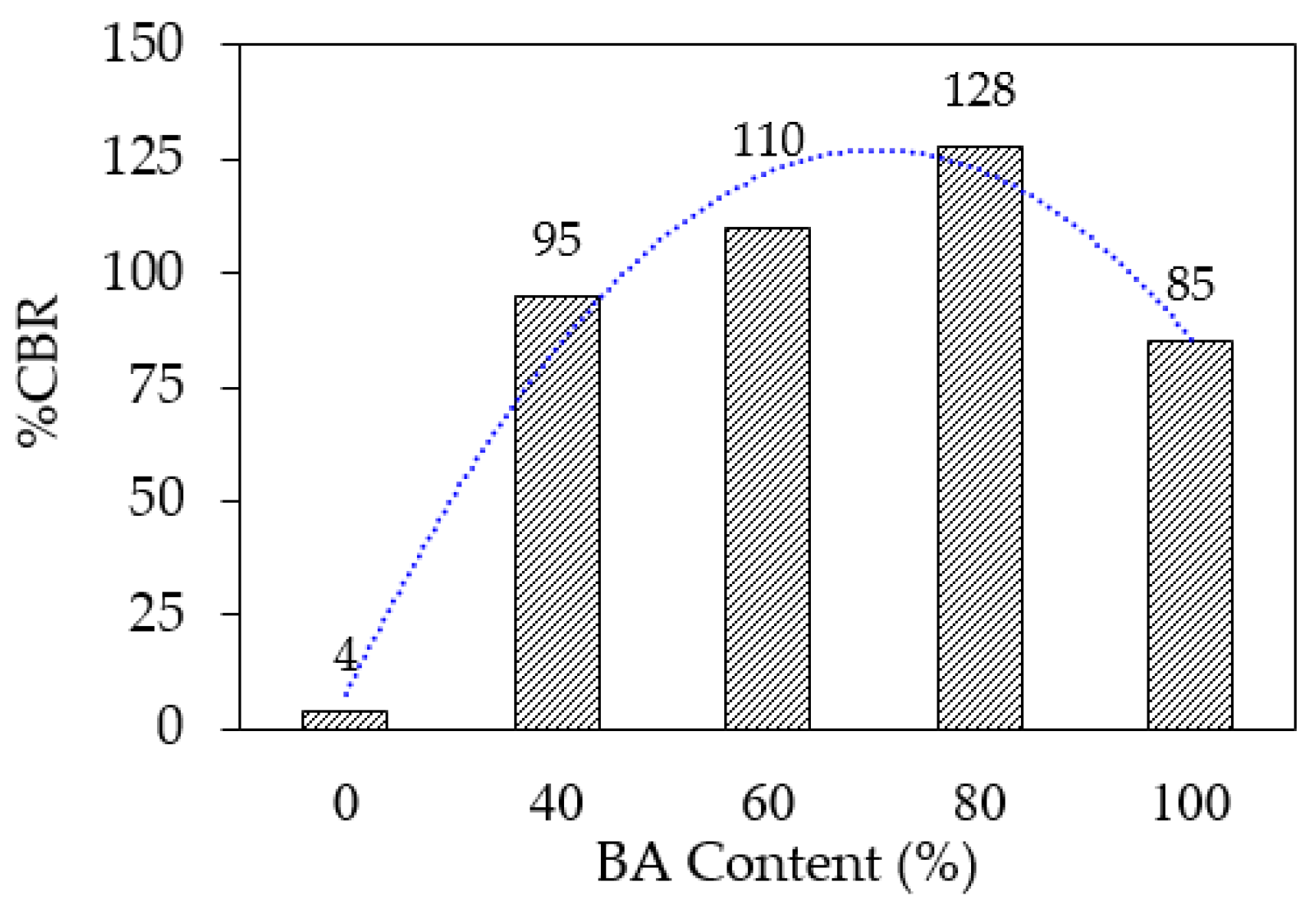
3.1. Compaction and CBR Characteristics

Figure 4 shows the typical compaction curves of the CSS specimens at a different BA and cement content. The compaction curves the γdmax and OMC for pure lateritic soil (LS) were 18.8 kN/m3 and 14.4%, respectively. Overall, all compaction curves of CSS specimens were lower than that of LS. As observed in Figure 4a–c, CSS specimens depicted a reduction in the γdmax values with the increase in the BA content. For example in Figure 4b, the γdmax decreased from 18.8 kN/m3 to 18.0, 17.42, 17.0, and 15.48 kN/m3 after replacement by BA of 40, 60, 80, and 100%, respectively. This decrease in the γdmax is related to the increase in the OMC of the mixtures, which describes that the LS treated with BA and cement specimens require a higher water content to reach the γdmax, compared to pure LS. The increase in the OMC was attributed to the replacement of coarse grains by the BA, which had a higher adsorption capacity than the LS [49]. The reduction in the γdmax was due to the fact that the BA had a specific gravity lower than that of the LS.
Figure 5 shows the CBR values of uncemented specimens after 4 days of soaking. The CBR value of the untreated LS was 4%, and this increased to 95, 110, 118, or 85% after blending with the BA at 40, 60, 80, or 100%, respectively. The XRD patterns of the uncemented (80% BA replacement) specimens are depicted in Figure 6a. As seen in Figure 6a, the main component of the specimen was quartz (SiO2) in a crystalline form. Kaolinite is a clay mineral, and quartz and calcite are non-clay minerals [9]. Therefore, an increase in the CBR value can be explained by the presence of calcium carbonate (CaO) in the BA, which affected the chemical reactions between the CaO and CO2 in the calcite form, including the pozzolanic reaction, which contributed to the high CBR value, which was confirmed by the XRD graphs in Figure 6a.

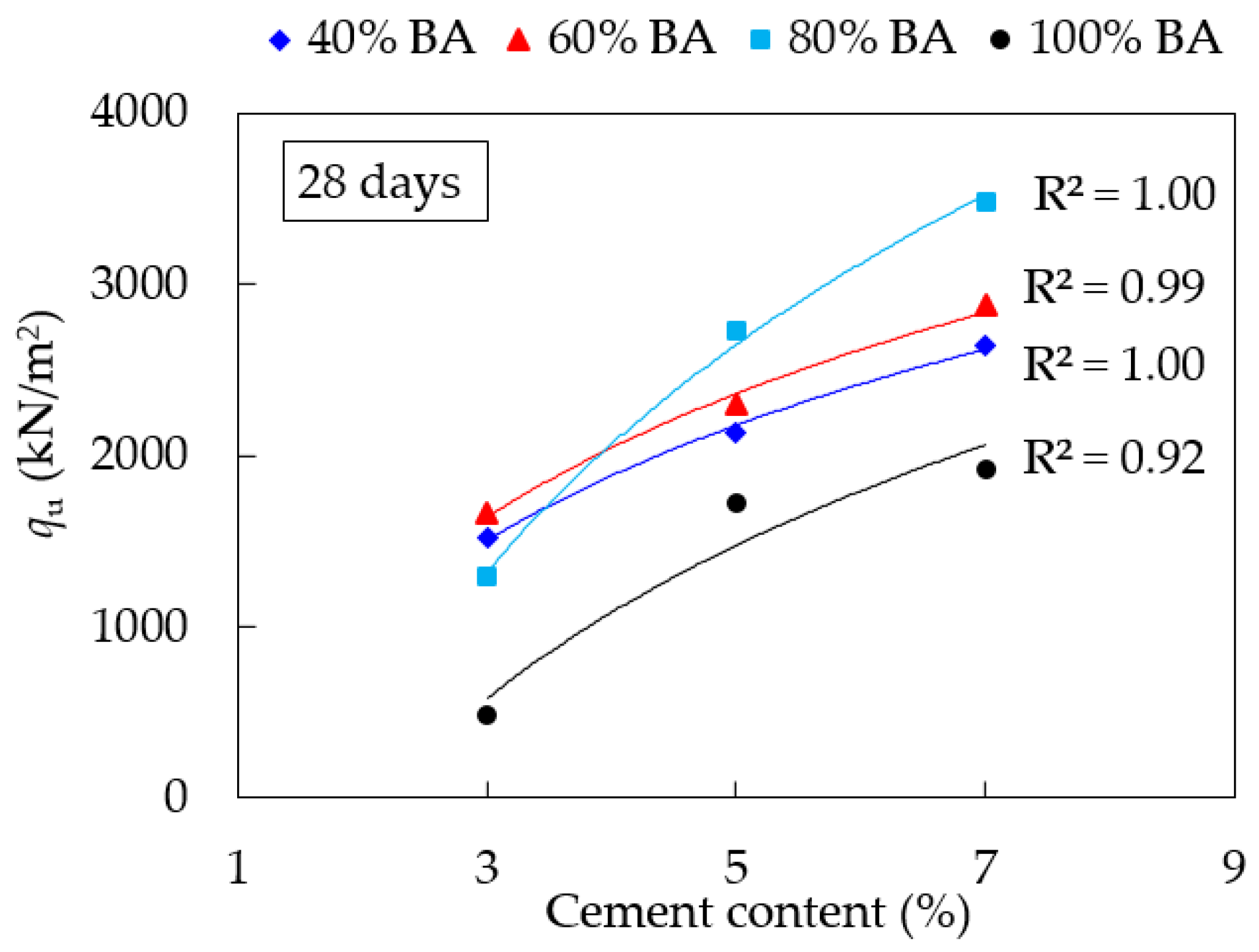
3.2. Effects of BA and HC Contents on Strength

The mean values of the qu and E50 obtained from the UC test for the CSS specimens are summarized in Table 4. The letters B and C refer to the dosages of the biomass bottom ash and cement, respectively. For example, B40C3 denotes the mixture with the replacement of LS by 40% BA, and is stabilized with 3% HC. Figure 7 depicts the variation in qu values and BA replacement contents for CSS specimens after 7 days of curing time. The minimum qu value for the soil–cement subbase at 7 days, as specified by the DOH of Thailand [32], is 689 kPa, as shown by the dashed line. Figure 7 shows that, with the exception of the specimen containing 100% BA and 3% cement, the majority of the specimens met the DOH specifications’ minimum values. The strength of all specimens with varying cement content followed a similar pattern, with an increasing trend with increasing cement content. When 40 and 60% BA content were added to specimens stabilized with 3% cement and 7% cement, the qu tended to increase. Beyond 60% BA addition, a downward trend in the qu was observed. While the specimens were stabilized at 5% cement, the qu increased as the BA content increased from 40 to 80%. The qu decreased as the BA content exceeded 80%. Figure 8 shows the relationship between the qu of the CSS specimens corresponding to curing times of 7, 14, and 28 days, with the only notable difference being in the cement content. As observed, the qu values of all CSS specimens increased progressively and logarithmically with the curing time. This trend was consistent with the previous investigation [12,50,51].

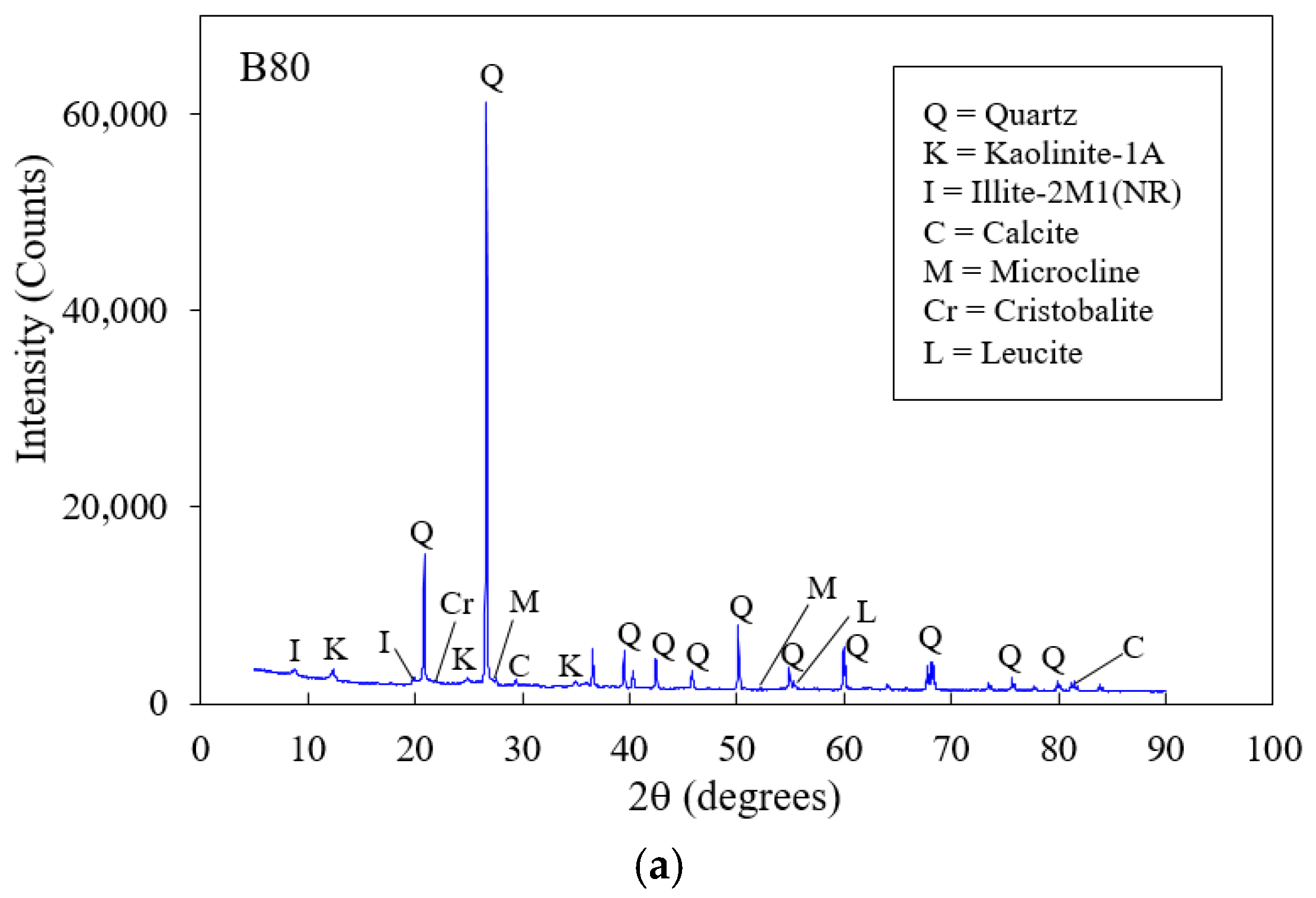
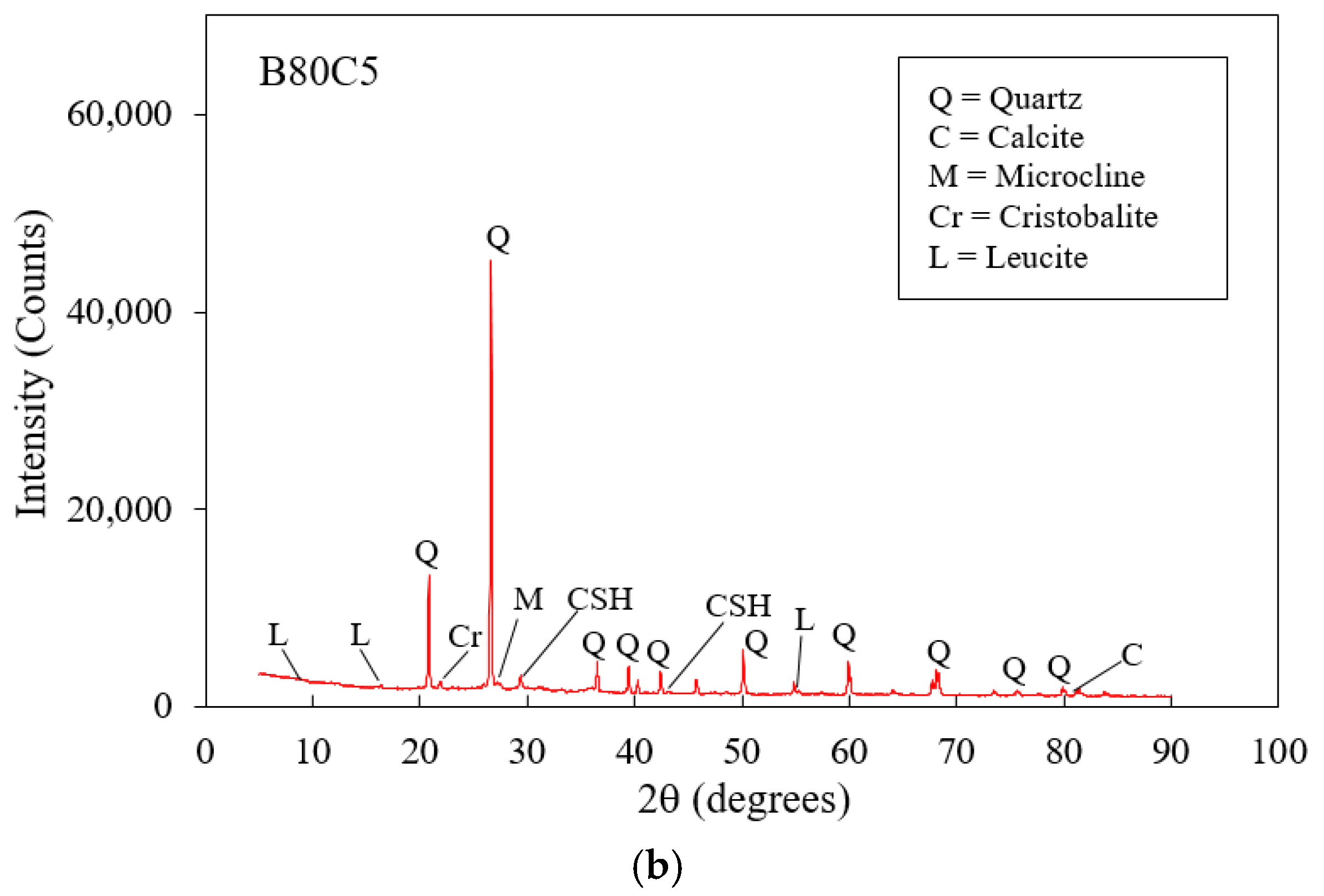
3.3. Leaching Analysis

The concentrations of the heavy metals obtained from the analysis with an Inductively Coupled Plasma-Optical Emission Spectrometer, Avio500, USA, is presented in Table 5. In this study, the selected samples from pure BA (solid sample) and from the leaching tests were examined. The leachate samples were collected from the effluent flowing out of the permeability test, comprising both the uncemented (i.e., B100, S20B80) and cemented (i.e., B80C5) specimens. For the pure BA, As, Cr, Cu, Ni, and Zn were detected, but Cd and Pb were not detected. According to the allowable limits of the soil’s quality standard requirements [52], the concentrations of As and Cr were higher than the allowable limits. For the leachate sample, As, Cd, and Pb were not detected. The concentrations of Cu and Zn from the sample of B100 and S20B80 were below the allowable limits of the groundwater quality standards [53,54]. However, the concentration of Cr was still higher than the allowable limits. This indicated that BA as a road material without the solidification/stabilization (S/S) technique may be unsuitable due to its negative environmental impact.
According to the US EPA, a material was considered hazardous waste if any detected heavy metal occurs at concentrations greater than 100 times the drinking water standard [55]. As observed in Table 5, the heavy metal concentrations of specimen B80C5 demonstrated that all parameters were within the allowable limit and threshold limit, which can confirm the safe utilization of BA as subbase material. This implied that the solubilities of silica, alumina, and clay minerals in LS are available for the reaction with calcium from cement and/or BA to form the cementitious hydrates, CAH and CSH. This contributed not only to the increased strength and reduced swell of the treated soil, but also to heavy metal immobilization via surface adsorption inclusion, and physical entrapment [56].

3.4. Pavement Design and Analysis

The stress-strain response results from the KENPAVE [39] were analyzed to investigate the overall performance by using the CSS as a subbase course. According to the strength and leaching criteria, B80C5 was selected as a suitable mixture and was subjected to the M–E pavement design. To compare the simulation results between unstabilized and stabilized subbase material, the thickness (h) of the HMA and the base course layer was considered constant, and the thickness of the subbase layer was varied by 200, 175, 150, and 125 mm, respectively.
The material’s properties as an input parameter model are shown in Table 6. For unstabilized subbase (Conventional material), the pavement structure had a 100 mm HMA surface course, 200 mm crushed stone base course, 200 mm granular subbase course, and an infinite extent of natural subgrade. The stabilized subbase had the same load condition as that of the unstabilized sample, but that was replaced with the CSS material’s property. Considering the input parameters of the stabilized subbase layer in Table 6, the qu value (2.70 Mpa) was obtained from the strength after 28 days for the B80C5 specimen. It also satisfied the minimum requirement for medium to high volume roads of the stabilized subbase (i.e., 2.0 MPa), as per the Austroads specification [57]. Thus, the MR value for the soil–cement subbase obtained from Equation (3) was 400 MPa.
Table 7 presents the M–E response at any location, including the surface deflection (Δz); the tensile strain (εt) at the bottom of the surface; and the vertical compressive strain (εc) at the top of the subgrade. As observed in Table 7, all Δz, εt, and εc values of the stabilized subbase had lower values than those of the conventional pavement, indicating the influences of the stabilized subbase. The value of Nf was more than Nr for the unstabilized subbase, which illustrates the critical number of repetitions (Ncr) that occurred with rutting failures. On the other hand, the Nf became less than that of the Nr for the thicknesses of 200 and 175 mm for the stabilized subbase, which indicates that the Ncr occurred with fatigue failures. This indicates that it is the effect of using the stabilized layer. However, when the thickness of the subbase was reduced to 150 or 125 mm, the Ncr became an Nr again.

4. Discussions

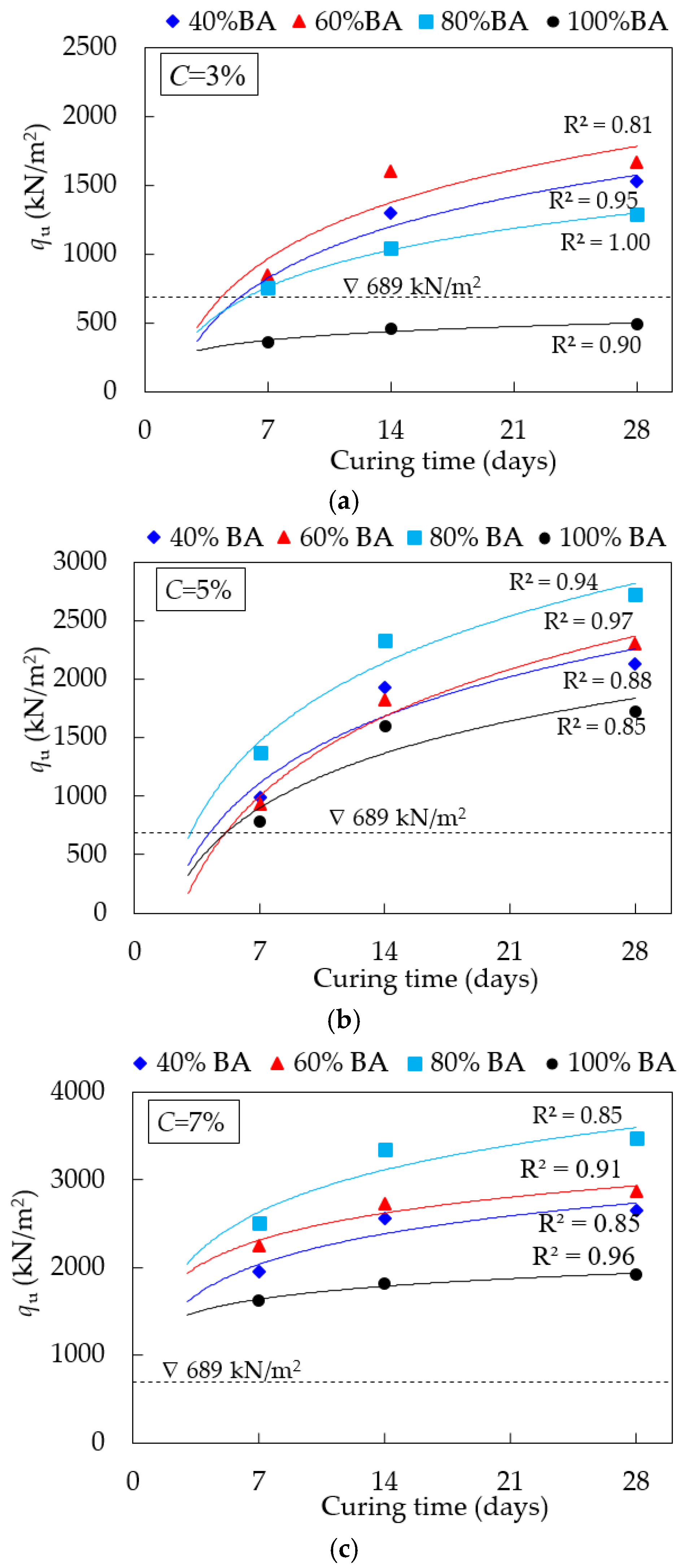
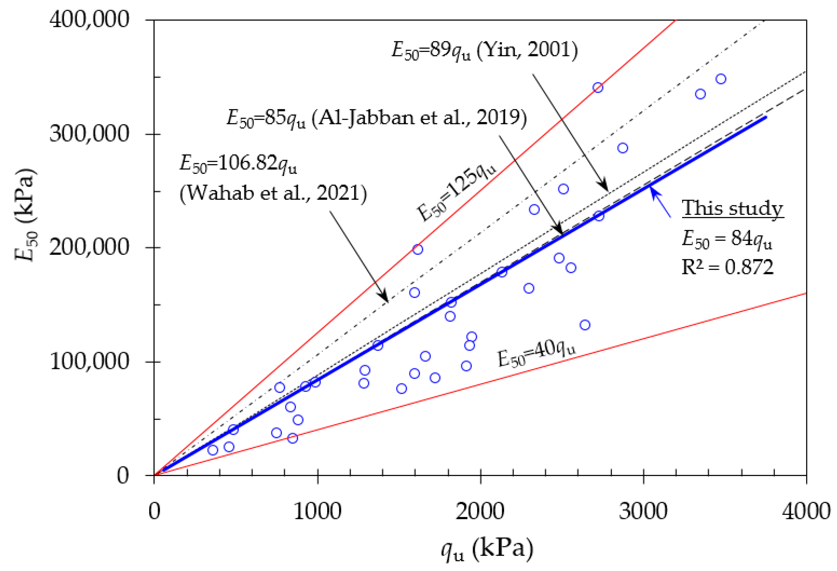
4.1. Strength Development and Stiffness

To analyze the effect of cement and BA content on the strength development for the CSS specimens, the qu value at 28 days of curing time and cement content relationship is presented in Figure 9. As observed, the strength increment was logarithm, and increased in trend with the increase in cement content. The qu value of the specimen with 80% BA showed a remarkable strength development versus other samples. Its strength increased by 3, 6, and 7 times for 3, 5, and 7% cement-treated samples, respectively, when compared with the untreated soil sample. Theoretically, the strength development of the cement-treated soil mainly depends on the hydration reaction and the pozzolanic reaction for short-term and long-term stages, respectively. Calcium-based stabilizers (e.g., cement) play an important role in producing calcium silicate hydrate (CSH), calcium aluminate hydrate (CAH), and calcium aluminosilicate hydrate (CASH) gels [9,12,44]. The main component of the specimen was quartz (SiO2) in crystal form, as shown by the XRD patterns of the CSS (B80C5) specimens after 28 days of curing time in Figure 6b. When the sample was treated with cement, the XRD results showed a reduction in the amount of crystals (i.e., compared with Figure 6a). This can be explained by the class F pozzolanic material not readily exhibiting self-cementing characteristics, and pozzolanic reactions are initiated upon cement addition, leading to the formation of CAH and CSH cementitious products. Overall, the CSH products are induced by the rapid hydration reaction between CaO in the HC and SiO2 in the LS and BA, which increases the qu. The results agreed quite well with the previous studies found by [58] for cement and biomass ash-treated soil.
The secant modulus (E50) obtained from the stress-strain curve was used to explain the stiffness of the CSS specimens. Figure 10 shows the relationship between the E50 and qu values of the CSS specimens (i.e., 3, 5, and 7% cement contents) at 7, 14, and 28 days of the curing time. Regarding Figure 10, the E50 increased linearly with an increase in the qu value, which was varied from 40qu to 125qu (i.e., red line in Figure 10) with the best fitting line of 84qu and the R2 of 0.872. It can be seen that the obtained E50-qu correlation from this study was consistent with the previous studies. For example, it was slightly lower than 106.82qu for the cemented-lateritic soil in Malaysia which was presented by Wahab et al. [12]. Similar results were reported by Al-Jabban et al. [59] for the cement-treated sandy clayey silt in Sweden (i.e., 85qu) and Yin [60] for the cement-treated Hong Kong marine deposit (i.e., 89qu). Therefore, it is suggested that the relationship between E50 and qu obtained from this study can be reliable in utilization in road pavement applications.

4.2. Benefit of BA for Subbase Stabilization

This study demonstrates the benefit of using BA as an aggregate material for flexible pavement. It was discovered that low-quality LS treated with BA and cement increased the qu value and met the DOH’s minimum requirement for the soil–cement subbase for all mixtures. This could demonstrate that using waste BA at a minimum of 40% (by weight of mix) as an aggregate with a cement content of 3 to 7% is feasible. As previously discussed, cementitious products play an important role in the strength development of CSS admixtures. The pore size reduction effect is another reason to support the positive results of CSS containing BA. This explains how cement stabilization improves soil structure by increasing inter-cluster cementation bonding and decreasing the pore space of the mix [61], resulting in improved pavement performance. Considering the TBR values as presented in Table 7, using the CSS as the subbase material could improve the life of the pavement by 1.27, 1.24, and 1.23 times for the subbase thicknesses of 200, 175, and 150 mm, respectively, compared with the conventional pavement system. For the subbase thicknesses of 125 mm, the TBRr value was reduced to 0.49, indicating that the stabilized subbase thickness should not be lower than 150 mm. According to the M–E method analysis presented in this study, the use of CSS containing BA as soil aggregate can reduce distress in flexible pavement. The current investigation, however, did not include any long-term durability studies. Concerning the contaminant issues, the heavy metal concentration of the proposed CSS mix confirmed that the leachate of heavy metal is below allowable limits acceptable for contaminants flowing into groundwater. It can therefore, be suggested that the knowledge gained will be critical for future research on similar waste BA materials in other areas.

5. Conclusions

The following conclusions can be drawn from the present study:
  • The soaked CBR values of the poor-quality LS were improved as a result of blending with BA, which met the requirement for subbase material in the Thailand highway specifications. However, the LS mixed with BA was still unsuitable for use as road material, because the Cr concentration still exceeded the national allowable limits for drinking water.
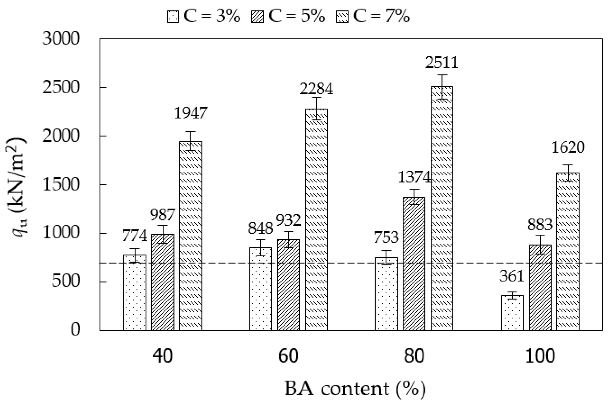
  • The results of the UC test on the CSS specimens indicated that it had a significant strength improvement, which satisfied the minimum requirement for soil–cement subbase course. To maximize the utilization of the BA, the blend of the LS with 80% BA and cement-stabilized with 5% is suggested for applications in the subbase layer of pavement. It had remarkable results in terms of geotechnical engineering properties and has no environmental impact.
  • The results of the M–E approach pavement analysis indicated that using the CSS presented in this study as a soil–cement subbase layer would reduce the layer thickness by a maximum of 25%; extend the service life of the pavement; and extend the fatigue life and the rutting life by 1.20–1.27 times and 1.23–2.23 times respectively.
  • The outcomes of this research could be helpful for the development of new mixtures for future use of recycled biomass bottom ash in pavement applications.

Author Contributions

Conceptualization, A.I. and A.L.; methodology, A.L.; software, A.L.; validation, A.I., P.P. and A.L.; formal analysis, A.I., P.P. and A.L.; investigation, A.I. and A.L.; resources, A.L.; data curation, A.I.; writing—original draft preparation, A.I. and A.L.; writing—review and editing, P.P. and A.L.; visualization, A.L.; supervision, P.P. and A.L.; project administration, A.L.; funding acquisition, A.L. All authors have read and agreed to the published version of the manuscript.

Funding

This research was funded by the Rajamangala University of Technology Srivijaya, Thailand.

Institutional Review Board Statement

Not applicable.

Informed Consent Statement

Not applicable.

Data Availability Statement

The data presented in this study are available on request from the corresponding author.

Acknowledgments

The authors gratefully acknowledge the support of the Department of Civil Engineering, Faculty of Engineering, Rajamangala University of Technology Srivijaya.

Conflicts of Interest

The authors declare no conflict of interest.

References

  1. Office of the National Economic and Social Development Board. National Strategy (2018–2037). 2018. Available online: https://sto.go.th/en/about/policy/20-year-strategic-plan (accessed on 8 April 2022).
  2. Rashid, A.S.A.; Latifi, N.; Meehan, C.L.; Manahiloh, K.N. Sustainable improvement of tropical residual soil using an environmentally friendly additive. Geotech. Geol. Eng. 2017, 35, 2613–2623. [Google Scholar] [CrossRef]
  3. Fredlund, D.G.; Rahardjo, H. Soil Mechanics for Unsaturated Soils; John Wiley&Sons, Inc.: New York, NY, USA, 1993. [Google Scholar]
  4. Koppejan, J.; Van Loo, S. The Handbook of Biomass Combustion and Co-Firing; Routledge: London, UK, 2012. [Google Scholar]
  5. Lu, Y.; Tian, A.; Zhang, J.; Tang, Y.; Shi, P.; Tang, Q.; Huang, Y. Physical and chemical properties, pretreatment, and recycling of municipal solid waste incineration fly ash and bottom ash for highway engineering: A literature review. Adv. Civ. Eng. 2020, 2020, 8886134. [Google Scholar] [CrossRef]
  6. López, E.L.; Vega-Zamanillo, A.; Pérez, M.A.C.; Hernández-Sanz, A. Bearing capacity of bottom ash and its mixture with soils. Soil Found. 2015, 55, 529–535. [Google Scholar] [CrossRef] [Green Version]
  7. Cabrera, M.; Galvín, A.P.; Agrela, F.; Carvajal, M.D.; Ayuso, J. Characterisation and technical feasibility of using biomass bottom ash for civil infrastructures. Constr. Build. Mater. 2014, 58, 234–244. [Google Scholar] [CrossRef]
  8. Paine, K.A.; Dhir, R.K.; Doran, V.P.A. Incinerator bottom ash: Engineering and environmental properties as a cement bound paving material. Int. J. Pavement Eng. 2002, 3, 43–52. [Google Scholar] [CrossRef]
  9. Jaritngam, S.; Somchainuek, O.; Taneerananon, P. An investigation of lateritic soil cement for sustainable pavements. Indian J. Sci. Technol. 2012, 5, 2603–2606. [Google Scholar] [CrossRef]
  10. Berra, M.; Mangialardi, T.; Paolini, A.E. Reuse of woody biomass fly ash in cement-based materials. Constr. Build. Mater. 2015, 76, 286–296. [Google Scholar] [CrossRef]
  11. Donrak, J.; Hoy, M.; Horpibulsuk, S.; Arulrajah, A.; Mirzababaei, M.; Rashid, A.S.A. Environmental assessment of cement stabilized marginal lateritic soil/melamine debris blends for pavement applications. Environ. Geotech. 2019, 1–7. [Google Scholar] [CrossRef]
  12. Wahab, N.A.; Roshan, M.J.; Rashid, A.S.A.; Hezmi, M.A.; Jusoh, S.N.; Norsyahariati, N.D.N.; Tamassoki, S. Strength and durability of cement-treated lateritic soil. Sustainability. 2021, 13, 6430. [Google Scholar] [CrossRef]
  13. Ghosh, A.; Subbarao, C. Hydraulic conductivity and leachate characteristics of stabilized fly ash. J Env. Eng. 1998, 124, 812–820. [Google Scholar] [CrossRef]
  14. Bruder-Hubscher, V.; Lagarde, F.; Leroy, M.J.F.; Coughanowr, C.; Enguehard, F. Utilisation of bottom ash in road construction: Evaluation of the environmental impact. Waste Manag. Res. 2001, 19, 545–556. [Google Scholar] [CrossRef]
  15. Yoon, S.; Balunaini, U.; Yildirim, I.Z.; Prezzi, M.; Siddiki, N.Z.J. Construction of an embankment with a fly and bottom ash mixture: Field performance study. Mater. Civ. Eng. 2009, 21, 271–278. [Google Scholar] [CrossRef]
  16. Dabo, D.; Badreddine, R.; De Windt, L.; Drouadaine, I. Ten-year chemical evolution of leachate and municipal solid waste incineration bottom ash used in a test site. J. Hazard. Mater. 2009, 172, 904–913. [Google Scholar] [CrossRef]
  17. del Valle-Zermeño, R.; Formosa, J.; Prieto, M.; Nadal, R.; Niubó, M.; Chimenos, J.M. Pilot-scale road subbase made with granular material formulated with MSWI bottom ash and stabilized APC fly ash: Environmental impact assessment. J. Hazard Mater. 2014, 266, 132–140. [Google Scholar] [CrossRef]
  18. Cabrera, M.; Galvín, A.P.; Agrela, F.; Beltran, M.G.; Ayuso, J. Reduction of leaching impacts by applying biomass bottom ash and recycled mixed aggregates in structural layers of roads. Materials 2016, 9, 228. [Google Scholar] [CrossRef] [Green Version]
  19. Selvi, P. Fatigue and rutting strain analysis on lime stabilized subgrades to develop a pavement design chart. Transp. Geotech. 2015, 2, 86–98. [Google Scholar] [CrossRef]
  20. Lekha, B.M.; Goutham, S.; Shankar, A.U.R. Evaluation of lateritic soil stabilized with Arecanut coir for low volume pavements. Transp. Geotech. 2015, 2, 20–29. [Google Scholar] [CrossRef]
  21. Sahu, V.; Srivastava, A.; Misra, A.K.; Sharma, A.K. Stabilization of fly ash and lime sludge composites: Assessment of its performance as base course material. Arch. Civ. Mech. Eng. 2017, 17, 475–485. [Google Scholar] [CrossRef]
  22. Anaokar, M.; Mhaiskar, S. Numerical analysis of lime stabilized capping under embankments based on expansive subgrades. Heliyon 2019, 5, e02473. [Google Scholar] [CrossRef] [Green Version]
  23. Yang, X.; Zhang, Y.; Li, Z. Embankment displacement PLAXIS simulation and microstructure behavior of treated-coal gangue. Minerals 2020, 10, 218. [Google Scholar] [CrossRef] [Green Version]
  24. Sultan, S.A.; Guo, Z. Evaluating the performance of sustainable perpetual pavement using recycled asphalt pavement in China. Int. J. Transp. Sci. Technol. 2016, 5, 200–209. [Google Scholar] [CrossRef]
  25. Loulizi, A.; Al-Qadi, I.L.; Elseifi, M. Difference between in situ flexible pavement measured and calculated stresses and strains. J. Transp. Eng. 2006, 132, 574–579. [Google Scholar] [CrossRef]
  26. Solanki, P.; Zaman, M.; Muraleetharan, K.K.; Timm, D. Evaluation of resilient moduli of pavement layers at an instrumented section on I-35 in Oklahoma. Road Mater. Pavement Des. 2009, 10, 167–188. [Google Scholar] [CrossRef]
  27. Solanki, P.; Zaman, M. Design of semi-rigid type of flexible pavement. Int. J. Pavement Res. Technol. 2017, 10, 99–111. [Google Scholar] [CrossRef] [Green Version]
  28. Galvín, A.P.; López-Uceda, A.; Cabrera, M.; Rosales, J.; Ayuso, J. Stabilization of expansive soils with biomass bottom ashes for an eco-efficient construction. Environ. Sci. Pollut. Res. 2020, 28, 24441–24454. [Google Scholar] [CrossRef]
  29. Barcelo, L.; Kline, J.; Walenta, G.; Gartner, E. Cement and carbon emissions. Mater. Struct. 2013, 47, 1055–1065. [Google Scholar] [CrossRef]
  30. Tosti, L.; Zomeren, A.V.; Pels, J.R.; Damgaard, A.; Comans, R.N.J. Life cycle assessment of the reuse of fly ash from biomass combustion as secondary cementitious material in cement products. J. Clean. Prod. 2020, 245, 118937. [Google Scholar] [CrossRef]
  31. Songkhla Province. Songkhla Provincial Development Plan (2018–2022). 2021. Available online: https://www.songkhla.go.th/news_develop_plan (accessed on 8 April 2022). (In Thai).
  32. Department of Highways (DOH). Standard of Soil-Cement Subbase; DH-S 206/2532; Department of Highways Standard: Bangkok, Thailand, 1989. (In Thai)
  33. Horpibulsuk, S.; Phetchuay, C.; Chinkulkijniwat, A.; Cholaphatsorn, A. Strength development in silty clay stabilized with calcium carbide residue and fly ash. Soils Found. 2013, 53, 477–486. [Google Scholar] [CrossRef] [Green Version]
  34. Fookes, P.G. Tropical Residual Soils: A Geological Society Engineering Group; Geological Society of London: London, UK, 1997. [Google Scholar]
  35. ASTM. Standard Specification for Coal Fly Ash and Raw or Calcined Natural Pozzolan for Use in Concrete; ASTM C 618; ASTM International: West Conshohocken, PA, USA, 2012. [Google Scholar]
  36. Thai Industrial Standards Institute (TISI). Hydraulic Cement; TIS 2594-2013; Industrial Product Standards: Bangkok, Thailand, 2013. (In Thai)
  37. ASTM. Standard Test Methods for Laboratory Compaction Characteristics of Soil Using Modified Effort (56,000 ft-lbf/ft3 (2700 kN-m/m3); ASTM D 1557; ASTM International: West Conshohocken, PA, USA, 2017. [Google Scholar]
  38. ASTM. Standard Test Method for California Bearing Ratio (CBR) of Laboratory-Compacted Soils; ASTM D 1883; ASTM International: West Conshohocken, PA, USA, 2016. [Google Scholar]
  39. Huang, Y.H. Pavement Analysis and Design, 2nd ed.; Prentice Hall Inc.: Hoboken, NJ, USA, 2004. [Google Scholar]
  40. Miller, G.A.; Cerato, A.B.; Snethen, D.R.; Holderby, E.; Boodagh, P. Empirical method for predicting time-dependent strength and resilient modulus of chemically treated soil. Transp. Geotech. 2021, 29, 100551. [Google Scholar] [CrossRef]
  41. AASHTO. AASHTO Guide for Design of Pavement Structures; American Association of State Highway and Transportation Officials (AASHTO): Washington, DC, USA, 2003. [Google Scholar]
  42. Heukelom, W.; Klom, A.J.G. Dynamics Testing as a Means of Controlling Pavement During and After Construction. In Proceeding of the International Conference on the Structure Design of Asphalt Pavement, Ann Arbor, MI, USA, 20–24 August 1962. [Google Scholar]
  43. Powell, W.D.; Potter, J.F.; Mayhew, H.C.; Nunn, M.E. The Structural Design of Bituminous Roads; TRRL Report 1132; Transport and Road Research Laboratory (TRRL): Berkshire, UK, 1984. [Google Scholar]
  44. Yoobanpot, N.; Jamsawang, P.; Simarat, P.; Pornkasem, J.; Likitlersuang, S. Sustainable reuse of dredged sediments as pavement materials by cement and fly ash stabilization. J. Soils Sediments 2020, 20, 3807–3823. [Google Scholar] [CrossRef]
  45. Sağlik, A.; Gungor, G. Resilient modulus of unbound and bituminous bound road materials. In Proceeding of the 5th Eurasphalt & Eurobitume Congress, Istanbul, Turkey, 13–15 June 2012. [Google Scholar]
  46. Lukjan, A.; Iyaruk, A.; Somboon, C. Evaluation on mechanical deterioration of the asphalt mixtures containing waste materials when exposed to corrosion solutions. Int. J. Eng. Technol. Innov. 2022, 12, 130–144. [Google Scholar] [CrossRef]
  47. Al-Hadidy, A.I.; Yi-qiu, T. Mechanistic approach for polypropylene-modified flexible pavements. Mater. Des. 2009, 30, 1133–1140. [Google Scholar] [CrossRef]
  48. Timm, D.; Birgisson, B.; Newcomb, D. Development of mechanistic-empirical pavement design in Minnesota. Transp. Res. Rec. 1998, 1629, 181–188. [Google Scholar] [CrossRef]
  49. Lynn, C.J.; Ghataora, G.S.; Dhir OBE, R.K. Municipal incinerated bottom ash (MIBA) characteristics and potential for use in road pavements. Int. J. Pavement Res. Technol. 2017, 10, 185–210. [Google Scholar] [CrossRef]
  50. Horpibulsuk, S.; Katkan, W.; Sirilerdwattana, W.; Rachan, R. Strength development in cement stabilized low plasticity and coarse grained soils: Laboratory and field study. Soils Found. 2006, 46, 351–366. [Google Scholar] [CrossRef] [Green Version]
  51. Yoobanpot, N.; Jamsawang, P. Effect of cement replacement by rice husk ash on soft soil stabilization. Kasetsart J. (Nat. Sci.) 2014, 48, 323–332. [Google Scholar]
  52. Ministry of Natural Resources and Environment, Thailand. Soil Quality Standards; The notification of the national environmental committee: Bangkok, Thailand, 2021. (In Thai)
  53. Ministry of Natural Resources and Environment, Thailand. Groundwater Quality Standards; The notification of the national environmental committee: Bangkok, Thailand, 2004. (In Thai)
  54. US Environmental Protection Agency: US EPA. National Primary Drinking Water Regulations; EPA: Washington, DC, USA, 2009.
  55. Wartman, J.; Grubb, D.G.; Nasim, A. Select engineering characteristics of crushed glass. J. Mater. Civ. Eng. 2004, 16, 526–539. [Google Scholar] [CrossRef]
  56. Dermatas, D.; Meng, X. Utilization of fly ash for stabilization/solidification of heavy metal contaminated soils. Eng. Geol. 2003, 70, 377–394. [Google Scholar] [CrossRef]
  57. Rechard, Y. The Development and Evaluation of Protocols for the Laboratory Characterisation of Cemented Materials; Austroads Technical Report, AP-T101/08; Austroads: Sydney, Australia, 2008. [Google Scholar]
  58. Cabrera, M.; Agrela, F.; Ayuso, J.; Galvin, A.P.; Rosales, J. Feasible use of biomass bottom ash in the manufacture of cement treated recycled materials. Mater. Struct. 2016, 49, 3227–3238. [Google Scholar] [CrossRef]
  59. Al-Jabban, W.; Laue, J.; Knutsson, S.; Al-Ansari, N. A comparative evaluation of cement and by-product petrit T in soil stabilization. Appl. Sci. 2019, 9, 5238. [Google Scholar] [CrossRef] [Green Version]
  60. Yin, J.-H. Stress-strain-strength characteristics of soft Hong Kong marine deposits without or with cement treatment. Lowland Technol. Int. 2001, 3, 1–13. [Google Scholar]
  61. Horpibulsuk, S.; Rachan, R.; Chinkulkitnuwat, A.; Raksachon, T. Analysis of strength development in cement-stabilized silty clay from microstructural considerations. Constr. Build. Mater. 2010, 24, 2011–2021. [Google Scholar] [CrossRef]
Figure 1. Grain size distribution curves of the LS, BA, and LS+BA.
Infrastructures 07 00066 g001
Figure 2. SEM images: (a) lateritic soil; (b) biomass bottom ash; (c) hydraulic cement.
Infrastructures 07 00066 g002
Figure 3. Pavement configuration.
Infrastructures 07 00066 g003
Figure 4. Compaction curves of the CSS specimens: (a) cement = 3%; (b) cement = 5%; (c) cement = 7%.
Infrastructures 07 00066 g004
Figure 5. Soaked CBR values of the uncemented specimens.
Infrastructures 07 00066 g005
Figure 6. X-ray diffraction patterns: (a) B80; (b) B80C5.
Infrastructures 07 00066 g006aInfrastructures 07 00066 g006b
Figure 7. The qu of CSS specimens for different BA and cement contents at 7 days of curing time.
Infrastructures 07 00066 g007
Figure 8. Strength development with the curing time of the CSS: (a) cement = 3%; (b) cement = 5%; (c) cement = 7%.
Infrastructures 07 00066 g008
Figure 9. Relationship between qu and cement content at 28 days of curing time.
Infrastructures 07 00066 g009
Figure 10. The relationship between the E50 and qu compared with the previous study.
Infrastructures 07 00066 g010
Table 1. Physical properties of the LS and BA.
MaterialsSpecific GravityConsistency Limit (%)D50 (mm)Soil Fraction (%)USCS Symbol
LLPLPIGravelSandSilt & Clay
LS2.755302190.15322147GC
BA2.405Non-plastic1.6026713SP
Table 2. Chemical compositions of the LS, BA, and HC.
MaterialsChemical Composing (%)LOI
SiO2Al2O3Fe2O3CaOMgOK2OSO3TiO2Na2OP2O5Other
LS59.7920.598.070.041.483.050.070.870.030.120.335.56
BA61.738.575.3211.41.775.020.170.710.141.170.463.54
HC15.123.492.9864.991.290.462.810.270.110.060.238.19
Table 3. Testing program.
TestingLS:BA ProportionsCement
Content (%)
Water
Content (%)
Curing Time (days)Remark
Compaction100:0, 60:40, 40:60, 20:80, 0:1000--Uncemented specimens
60:40, 40:60, 20:80, 0:1003, 5, 7--CSS specimens
Soaked CBR100:0, 60:40, 40:60, 20:80, 0:1000OMC4Uncemented specimens
UC test60:40, 40:60, 20:80, 0:1003, 5, 7OMC7, 14, 28CSS specimens
Table 4. qu and E50 of the CSS specimens with different curing times.
SpecimensBA Content
(%)
Cement
Content
(%)
qu (kPa)E50 (kPa)
Curing Time (Days)Curing Time (Days)
7142871428
B0C000482482482482482482
B40C34037741294152277,40092,42976,100
B60C36038481602166632,61589,000104,125
B80C3803753839129037,65059,92980,625
B100C3100336145948522,56325,50040,417
B40C54059871933213682,250113,706178,000
B60C56059321823229977,667151,917164,214
B80C5805137423322726114,500233,200340,750
B100C510058831600172248,938160,00086,100
B40C7407194725562647121,688182,571132,350
B60C7607228427312874207,000227,583287,400
B80C7807251133503477251,100335,000347,700
B100C71007162018181916198,417139,84695,800
Table 5. Heavy metal concentrations.
From Solid SampleFrom Leachate Sample
B100
(mg/kg)
Allowable Limits (mg/kg) [52]B100
(ppm)
B80C0
(ppm)
B80C5 (ppm)Allowable Limits (ppm)
[53]/[54]
Threshold Limit (ppm)
[53]/[54]
Arsenic (As)14.806NDNDND0.01/0.011.00/1.00
Cadmium (Cd)ND67NDNDND0.003/0.0050.30/0.50
Chromium (Cr)82.8617.50.0650.0520.02250.05/0.105.00/10.00
Copper (Cu)16.6029200.1020.0810.07311.00/1.00100.00/100.00
Nickel (Ni)16.64436.50.0080.0060.00320.02/-2.00/-
Lead (Pb)ND400NDNDND0.01/0.0151.00/1.50
Zinc (Zn)32.02 -0.0170.0160.01055.00/5.00500.00/500.00
Note: ND = not detected.
Table 6. Input model parameters.
Model LayerPavement Layerh(cm)Conventional MaterialsStabilized-Subbase Materials
MR (MPa)νCBR (%)MR (MPa)νCBR (%)qu (MPa)
1HMA1030000.35-3,0000.35--
2Base203000.35853000.3585-
3Subbase20, 17.5, 15, 12.51500.35304000.30-2.70
4Subgrade500.405500.405-
Table 7. Results of mechanistic–empirical design.
Subbase CourseConstant HMA and Base Course
Subbase Thicks, mmΔz (mm)εt (×10−4)εc (×10−4)Nf (×106)Nr (×106)TBRfTBRr
Unstabilized2000.552.414.441.161.081.001.00
Stabilized2000.482.243.631.472.411.272.23
1750.492.263.901.441.811.241.67
1500.512.254.201.391.341.201.23
1250.602.355.311.250.531.080.49
Publisher’s Note: MDPI stays neutral with regard to jurisdictional claims in published maps and institutional affiliations.

