Article

A Compact Slotted UWB Antenna Based on Characteristics Mode Theory for Wireless Applications

by
Subhash Bodaguru Kempanna
1,
Rajashekhar C. Biradar
1,
Tanweer Ali
2,
Vikash Kumar Jhunjhunwala
3,
Sarun Soman
3 and
Sameena Pathan
4,*
1
School of ECE, REVA University, Bangalore 560064, India
2
Department of Electronics and Communication Engineering, Manipal Institute of Technology, Manipal Academy of Higher Education, Manipal 576104, India
3
Department of Electrical and Electronics Engineering, Manipal Institute of Technology, Manipal Academy of Higher Education, Manipal 576104, India
4
Department of Information and Communication Technology, Manipal Institute of Technology, Manipal Academy of Higher Education, Manipal 576104, India
*
Author to whom correspondence should be addressed.
Designs 2023, 7(6), 141; https://doi.org/10.3390/designs7060141
Submission received: 1 November 2023 / Revised: 20 November 2023 / Accepted: 21 November 2023 / Published: 12 December 2023
(This article belongs to the Special Issue Advances in Communication Technology with Artificial Intelligence)

Abstract

:
The development of electronic systems and wireless communication has led to a proportional increase in data traffic over time. One potential solution for alleviating data congestion is to augment the bandwidth capacity. This study presents a novel asymmetric circular slotted semi-circle-shaped monopole antenna design using a defective ground structure. The extended ultrawide bandwidth is achieved by implementing a design where the semi-circle radiator is etched in a specific asymmetric circular slot. This involves etching a circle with a radius of 1.25 mm at the center of the radiator, as well as a succession of circles with a radius of 0.75 mm along the edges of the radiator. In addition, the ground plane is situated at a lower elevation and features a U-shaped truncation that has been etched onto its surface. The expansion of the impedance bandwidth can be accomplished by making adjustments to the radiator and ground plane. The UWB antenna under consideration possesses a geometric configuration of 21.6 × 20.8 × 1.6 mm3 and the antenna is fabricated using an FR-4 glass epoxy substrate. The UWB antenna operates throughout the frequency range of 2.2–16.5 GHz, exhibiting a gain of at least 3.45 dBi across the entire impedance bandwidth and the maximum peak gain of 9.57 dBi achieved at the mid-resonance frequency of 10.5 GHz. The investigation of the antenna’s physical properties is conducted utilizing characteristic mode analysis. The investigation also includes an analysis of the time-domain characteristics, revealing that the group delay was found to be less than 1 ns across the operational frequency range. The predicted and measured findings demonstrate consistency and confirm that the suggested antenna is suitable for electronic systems and wireless applications.

1. Introduction

The increasing prevalence of wireless connectivity in electronic devices has resulted in a growing need for rapid data transfer, particularly in vital industries such as healthcare, multimedia, radar, and object-tracking applications. Nevertheless, the increasing utilization of data across multiple applications has placed significant pressure on conventional narrow-band communication routes [1,2]. In light of this difficulty, the Federal Communication Commission (FCC) has discovered a potential resolution through the utilization of the unrestricted 7.5 GHz spectrum, which encompasses frequencies ranging from 3.1 GHz to 10.6 GHz [3]. This particular range is frequently referred to as ultrawide bandwidth. The utilization of ultrawideband (UWB) technology offers numerous benefits, such as a substantially wider range of impedance bandwidth, improved resistance to noise interference, decreased power spectral density, and superior data resolution. Within the domain of communication systems, the antenna assumes a crucial role as a critical constituent, and its appropriate design holds the utmost significance in guaranteeing the overall performance of the system [4,5]. However, the process of building a highly efficient UWB antenna is not devoid of intricacies. Engineers encounter many obstacles pertaining to compactness, avoidance of electromagnetic interference, attainment of constant gain, and optimization of radiation parameters. Various types of antennas are available, such as apertures, wire antennas, and conical antennas. However, microstrip antennas have become increasingly popular due to their compact design, ease of production, and cost efficiency. Nevertheless, it is well acknowledged that microstrip antennas have historically exhibited limited bandwidth. In order to address this constraint and facilitate the utilization of the wider bandwidths required for UWB applications, it becomes essential to implement targeted structural modifications. These developments encompass techniques such as ground plane defection, metamaterial unit or surface embedding, and the integration of parasitic components onto either the radiator or the ground plane [6,7,8,9,10]. The development of contemporary communication systems may be aided by this proactive approach to improving microstrip antenna performance, which shows tremendous potential for addressing the growing need for high-speed, low-latency data transfer in a variety of electronic applications.
The literature that is currently available demonstrates the wide range of structures that have been developed in the field of antenna design over the last 20 years to obtain greater bandwidth capabilities. The initial efforts in this field involved the development of planar UWB antennas, compact fractal-based designs, UWB antennas using metamaterials, and Vivaldi antennas. These many advancements have together contributed to the broad range of UWB antenna technologies [11,12]. One strategy entailed modifying a typical rectangular monopole antenna to fully utilize the UWB operating frequency range. The process of adaptation involved the development of a curved structure adjacent to the feedline and a subsequent reduction in the ground plane [13]. The antenna that was obtained had a condensed structure with dimensions of 17 × 23 × 1.5 mm3 and functioned within the frequency spectrum spanning from 3–10 GHz. The incorporation of slots on the radiator results in the introduction of a fringing field effect and an extra inductance element, effectively augmenting the bandwidth of the antenna. The novel design technique that was showcased involved an antenna with a sprocket gear construction. This antenna had a total size of 27 × 27 × 1.6 mm3 and functioned within the frequency range of 2–12 GHz, as suggested in reference [14]. The modification made to the structure of the radiator played a pivotal role in expanding the bandwidth of impedance. The research in [15] presented a simple yet efficient design that combines a circle and a rectangle with a smaller ground plane to provide UWB operation between 3.5 and 12.4 GHz. The process of adaptation in question entailed the manipulation of the ground plane by reducing its elevation and the introduction of a fringing field onto the radiator. This was achieved by incorporating a rectangular shape into the circular monopole antenna. The antenna that was produced has a total size of 21.5 × 13 × 1.6 mm3.In addition, a coplanar waveguide (CPW) design with a mug-like construction was introduced in reference [16]. The dimensions of the CPW were specified as 25 × 22 × 1.6 mm3, and it operated within the frequency range of 3–11 GHz. The proposed design involved the incorporation of optimized parasitic elements into a conventional rectangular monopole structure to obtain the necessary UWB spectrum. Specifically, in [17], a pentagon-structured fractal monopole antenna based on CPW was created. The UWB antenna under consideration has a geometric configuration measuring 24 × 30 × 0.7 mm3 and functions within a frequency range spanning from 3 to 12.7 GHz. The aforementioned antenna advancements encompass a wide range of approaches that seek to attain UWB capabilities. Each of these approaches is characterized by its distinct geometry and design alterations, which are tailored to fulfill the requirements of contemporary communication systems and applications.
The existing body of literature provides numerous structures, techniques, and methodologies for designing UWB antennas. However, achieving a design that effectively balances simplicity and effectiveness, maintains stable radiation properties, demonstrates consistent gain throughout the impedance bandwidth, and possesses superior time-domain characteristics continues to be a persistent challenge. The objective of this study is to tackle the aforementioned difficulties by introducing an innovative semi-circular monopole antenna design. This design incorporates a unique arrangement of circular slots on the radiator and a deliberately lowered ground plane, specifically optimized for operating within the frequency range of 2.2–16.5 GHz. The suggested UWB antenna exhibits a gain of over 3.45 dBi over the whole impedance bandwidth. The radiator incorporates asymmetric circular slots strategically to introduce disruptions in the uniform distribution of current, resulting in the formation of localized current channels. The implementation of this novel methodology improves the performance attributes of the antenna, hence augmenting its notable impedance bandwidth. In addition, the decrease in the ground plane size plays a role in expanding the antenna’s impedance bandwidth, thus augmenting its overall performance. To offer a thorough comprehension of the antenna design, the paper is structured as follows: Section 2 explores the intricate aspects of the antenna design methodology, providing a comprehensive explanation of the fundamental principles and methodologies employed in the creation of the nonagon monopole antenna with circular slots and a decreased ground plane. Section 3 of the paper introduces a characteristic mode analysis (CMA) of the proposed UWB antenna, providing insights into its fundamental operating modes and resonant features. Section 4 of the article functions as a forum for deliberating on the experimental results and conducting a comparative analysis of the performance of the devised antenna compared to pre-existing antenna designs. This comparison offers a significant reference point for assessing the efficacy of the developed antenna.
To sum up, this article makes a substantial contribution to the field of UWB antenna design by providing a straightforward but incredibly efficient method for attaining stable radiation characteristics, steady gain, and enhanced time-domain performance. The semi-circular monopole antenna, which incorporates circular slots, disrupts the uniform current distribution by forming local current channels, and a decreased ground plane demonstrates noteworthy performance outcomes in the frequency range of 2.2–16.5 GHz.

2. Antenna Design

The semi-circular monopole antenna, which was initially built with a fully implemented ground plane, was carefully engineered to achieve resonance at a precise frequency of 4 GHz. To enhance its capabilities as a UWB antenna, a significant alteration was implemented by introducing a circular slit in the core of the radiator. The inclusion of this asymmetric circular aperture played a crucial role in attaining the requisite coverage of the UWB spectrum, enhancing the antenna’s capacity to transmit and receive signals across a wider range of frequencies. The resonant frequency ( f r = 5.4   G H z ) is used to calculate the radius of the circular monopole antenna with a microstrip feedline, as represented in Equations (1) and (2) [18]. This configuration offers an impedance bandwidth of 2.2–16.5 GHz.
r = F 1 + 2 h π ε r F ln π F 2 h + 1.7726
where h = 1.6   m m the thickness of the substrate and F is given by,
F = 8.791 × 10 9 f r ε r
The fringing field spreads from the patch boundary to the ground plane, resulting in an effective radius. The circular patch’s bordering field may lengthen the circle’s radius. As a result, the effective radius ( r e f f ) is calculated as given in Equation (3).
r e f f = 1.8412   c 2 π f r ε r
where c = 3 × 10 11   m m / s .
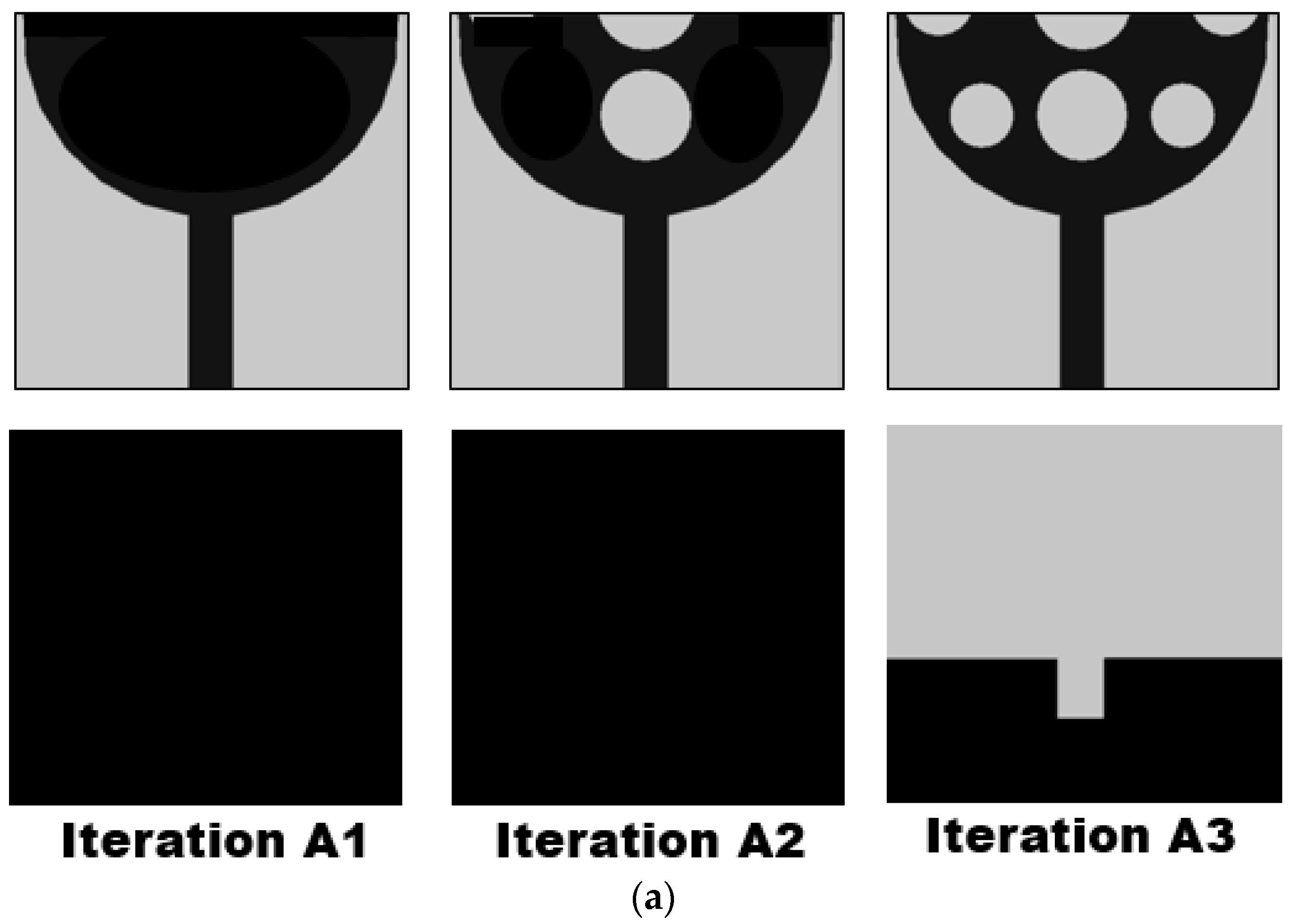
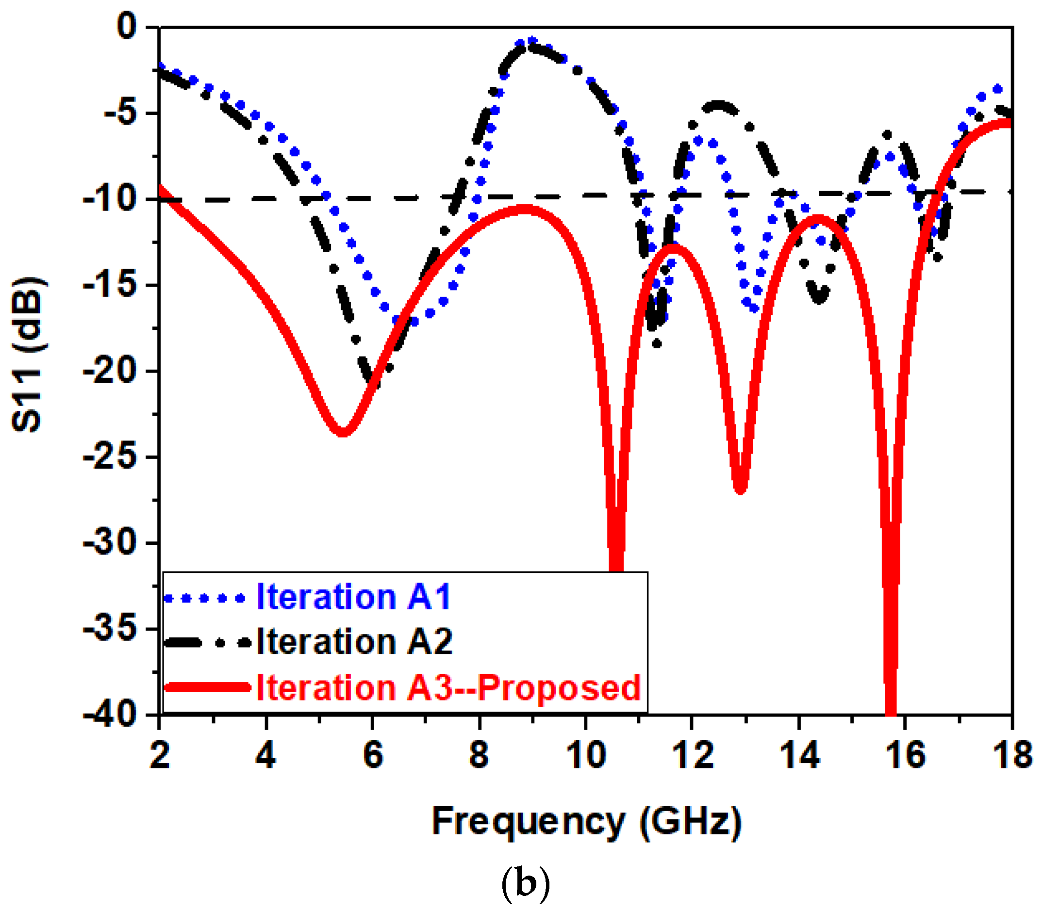
Figure 1 visually represents the several phases of antenna design evolution, emphasizing their influence on the reflection coefficient (S11) curve, which is a critical measure for evaluating antenna performance. The provided diagram functions as a graphical depiction of the impact of the antenna design alterations on the successful attainment of the targeted UWB performance.
Initially, as seen in Figure 1a, the alteration made to the structure of the radiator resulted in the formation of both open and closed channels, thereby disrupting the even distribution of the current. In iteration A1, when no slots were etched on the radiator, the impedance matching was poor and multiband operation is seen from 4.5–16.2 GHz, as depicted in Figure 1b. Etching of slots in the middle of the radiator, as seen in iteration A2, changes the current path length, which helps in creating wide-band operation ranging from 12.5–14.5 GHz. The other bands tend to achieve better impedance bandwidth as compared to iteration A1, as depicted in 
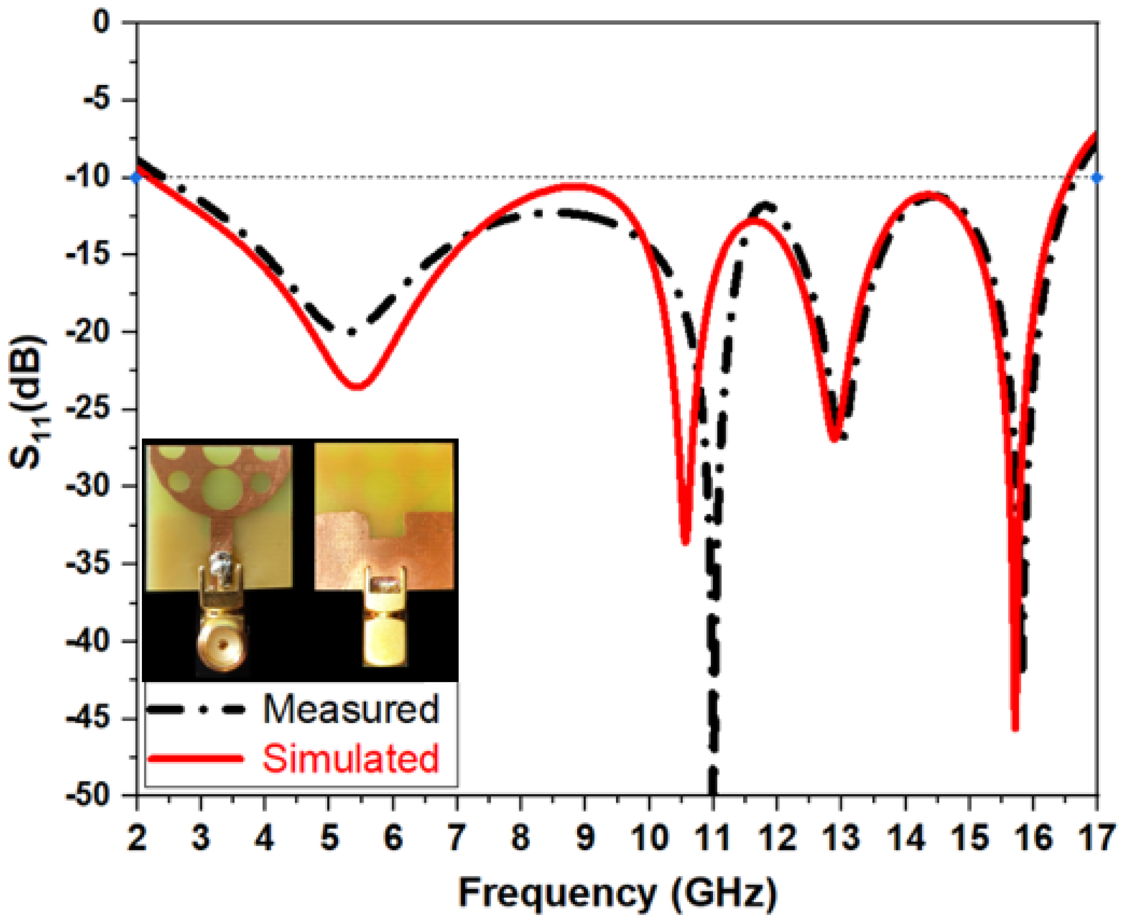
Figure 1b. In iteration A3, when the asymmetric slots were etched on the radiator, the impedance matching improved further, and the antenna showed an operating bandwidth (s11 < −10 dB) ranging from 2.2–16.5 GHz. On the other hand, modifications were made to the antenna’s ground plane from iteration A1 to A3, as seen in Figure 1a, to improve its efficiency even more. The ground plane was intentionally lowered, and a U-shaped truncation slot was deliberately introduced at the middle of the ground plane, as seen in Figure 1a. The implementation of these design modifications played a crucial role in attaining a wider range of impedance bandwidth, as seen in Figure 1b. The aforementioned disturbance resulted in the emergence of localized current channels, making a substantial contribution to the enhanced performance of the antenna.
The U-shaped truncation in the ground part played a significant role in modifying the lumped characteristics of the transmission line, leading to a reduction in the quality factor and an increase in the operational bandwidth of the antenna.
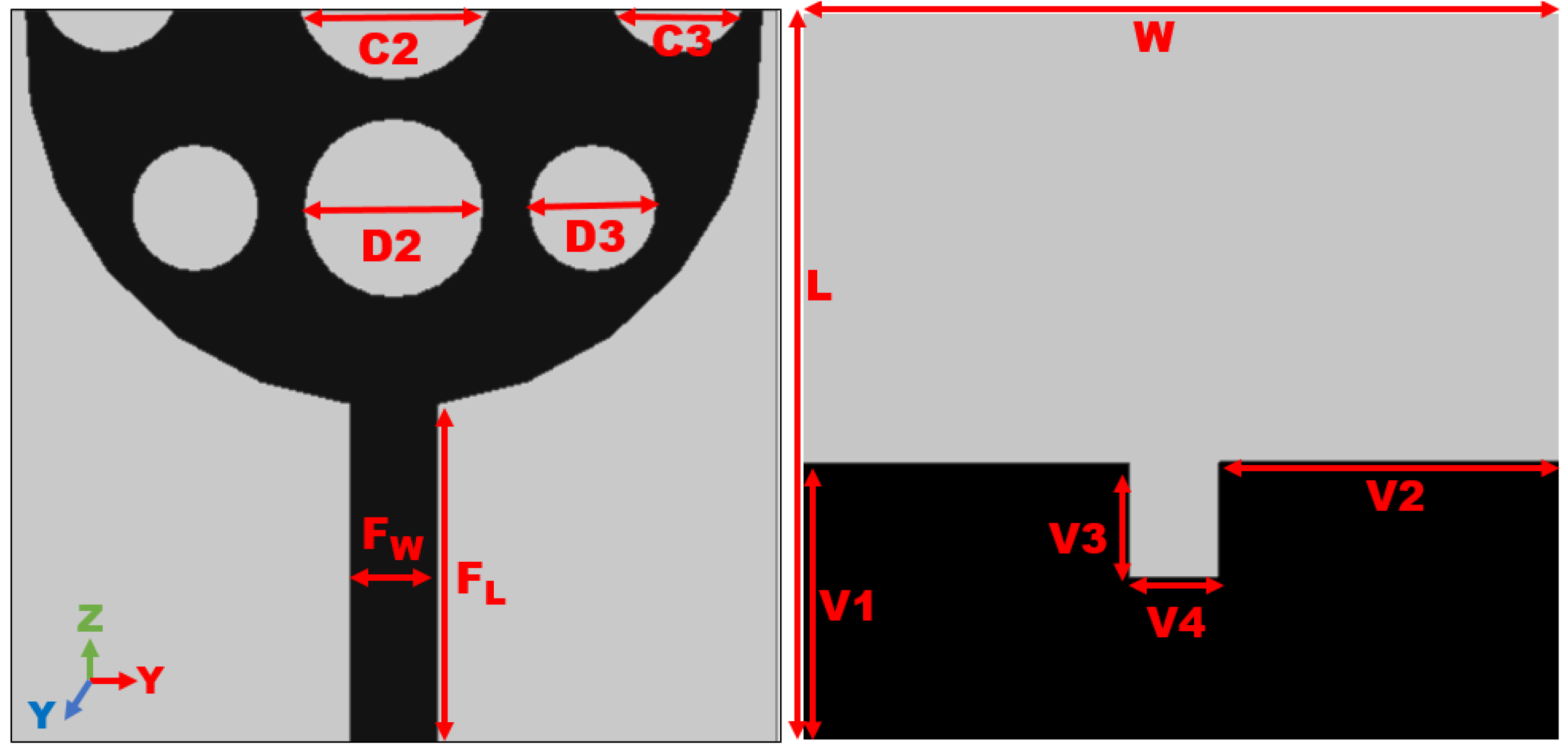
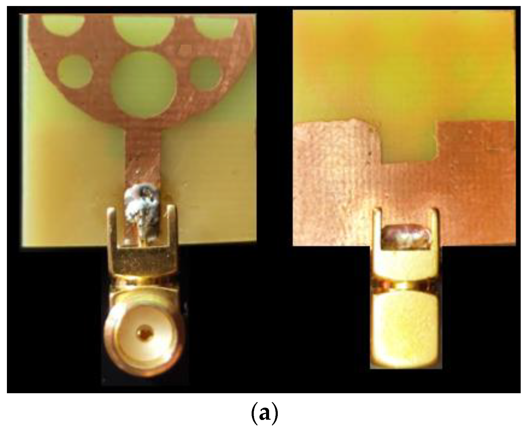
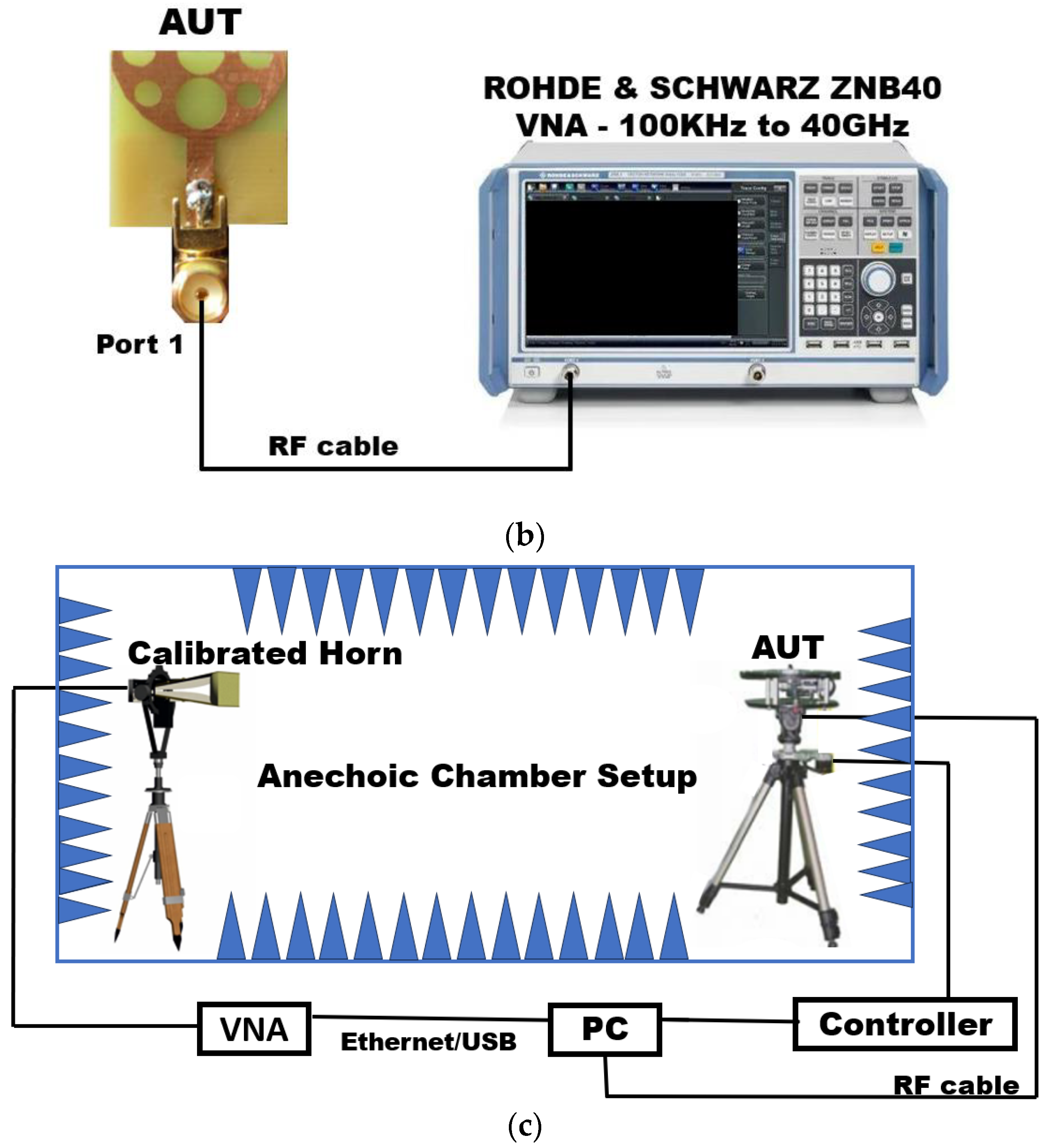
The UWB antenna is constructed using an FR4- glass epoxy substrate, with a total physical size of 21.6 × 20.8 × 1.6 mm3. The antenna shows good impedance matching throughout its operation range from 2.2 to 16.5 GHz. Figure 2 and Table 1 present comprehensive geometric data about the proposed antenna design, furnishing significant insights into its dimensions and essential parameters.
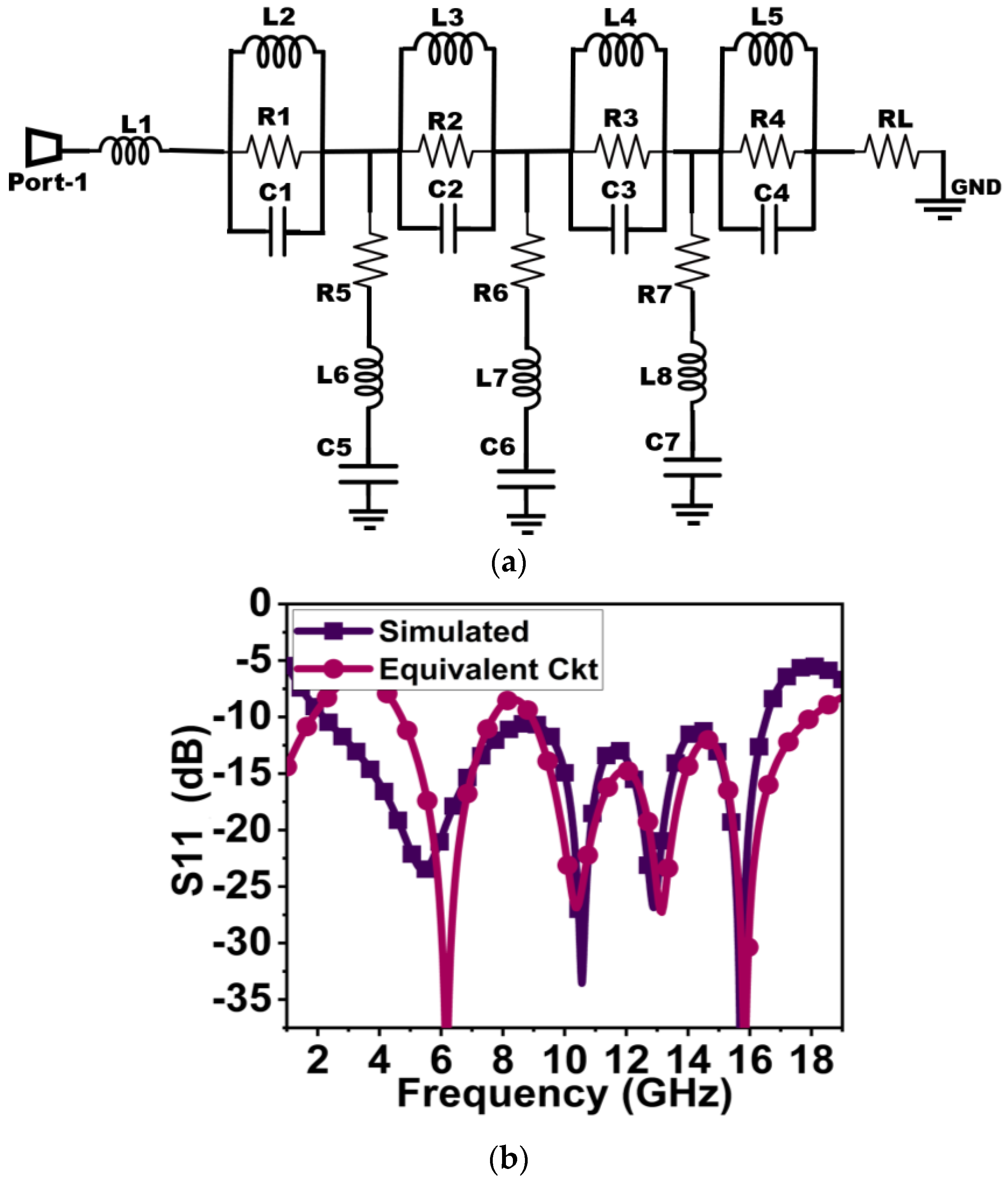
The designed antenna’s equivalent circuit, illustrated in Figure 3, is modeled through Applied Wave Research (AWR) software v22.1 from cadence (San Jose, CA, USA). The derivation of this model relies on the reflection coefficient response. Instances, where the reflection coefficient drops below −10 dB, are depicted using RLC elements in an equivalent resonant circuit model. Figure 3 highlights five observed resonant modes within the frequency range of 2.2 to 16.5 GHz. The tabulated lumped component values (R, L, and C) in Table 2 for the equivalent circuit undergo slight tuning using AWR software to attain the desired UWB characteristics. The impedance is represented by four parallel RLC cells connected in series, resonating at respective frequencies. Figure 4 illustrates a comparison between reflection coefficients obtained from HFSS and AWR. A slight shift in the results is evident, attributed to adjustments made in the capacitors, inductors, and resistors during the AWR simulation to achieve the desired response, causing a resonance frequency shift from the HFSS simulation results.

3. Parametric Analysis

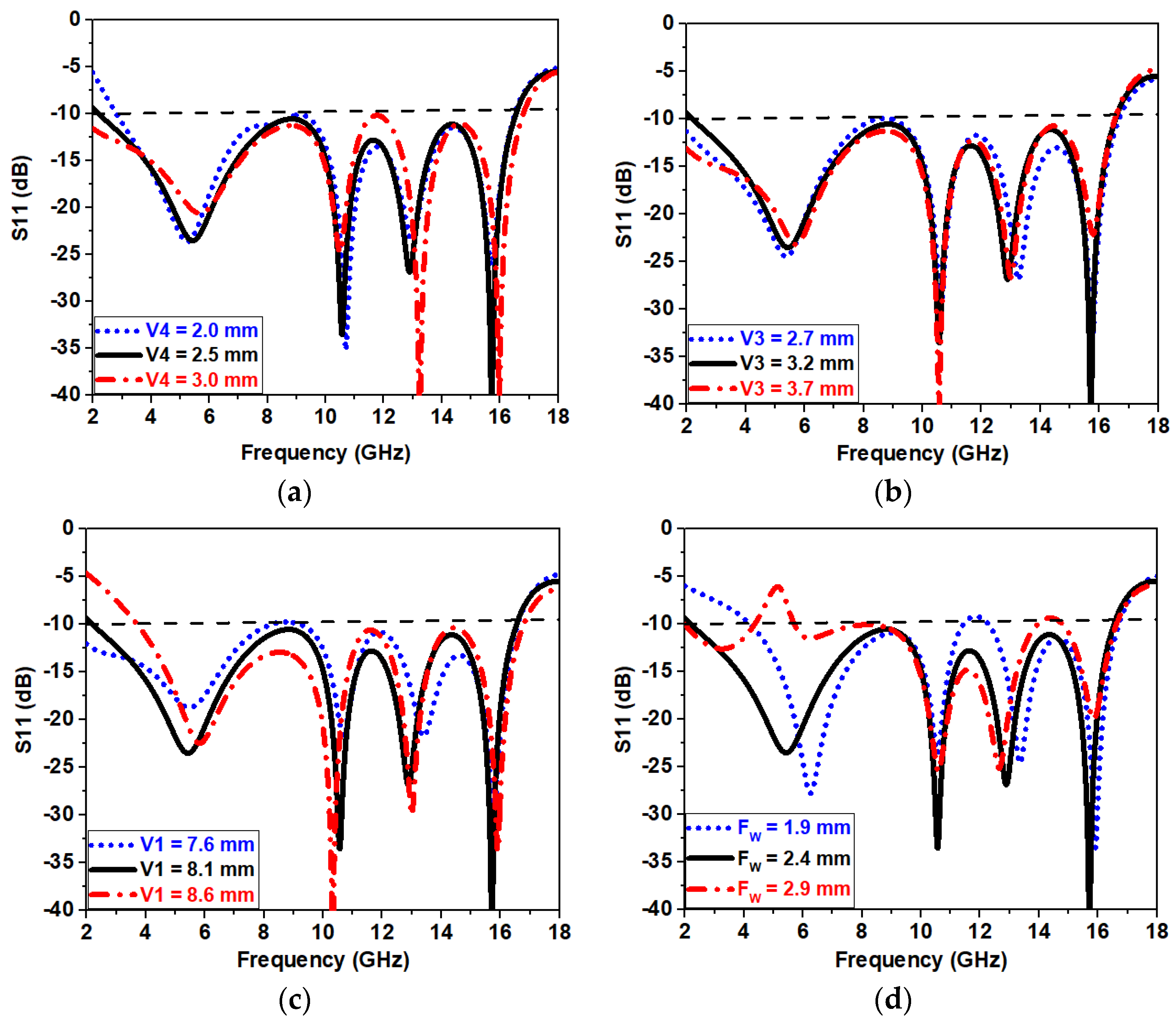
A comprehensive parametric study was carried out to determine the antenna’s ideal configuration as depicted in Figure 4a–f. The present study encompassed a methodical manipulation of multiple factors to assess their influence on the performance of the antenna. One of the criteria taken into consideration was the adjustment of the U-shaped truncation on the ground plane, referred to as V4, in increments of 0.5 mm. Disruptions in the S11 curves at frequencies were found, as depicted in Figure 4a. As a result, the best value for V4 was determined to be 2.5 mm, achieving a harmonious equilibrium between impedance bandwidth and antenna performance. The V3 was subjected to changes in ±0.5 mm steps, ranging from 2.7 mm to 3.7 mm. The investigation revealed that V3 values of 2.7 mm and 3.7 mm had a detrimental effect on the S11 curves within the frequency range, as depicted in Figure 4b. As a result, it was discovered that V3 exhibited the highest level of effectiveness when its width was set at 3.2 mm, as depicted in Figure 4b. Similarly, the optimum value of S11 is obtained when V1 is set at 8.1 mm, as seen in Figure 4c. Additionally, the feedline (FW) width was regularly changed in increments of 0.5 mm, spanning from 1.9 mm to 2.9 mm. The observed impact of this parameter on both S11 is shown in Figure 4d. The observed differences in the width of the feedline indicate that the selection of feedline width has a considerable impact on the performance characteristics of the antenna.
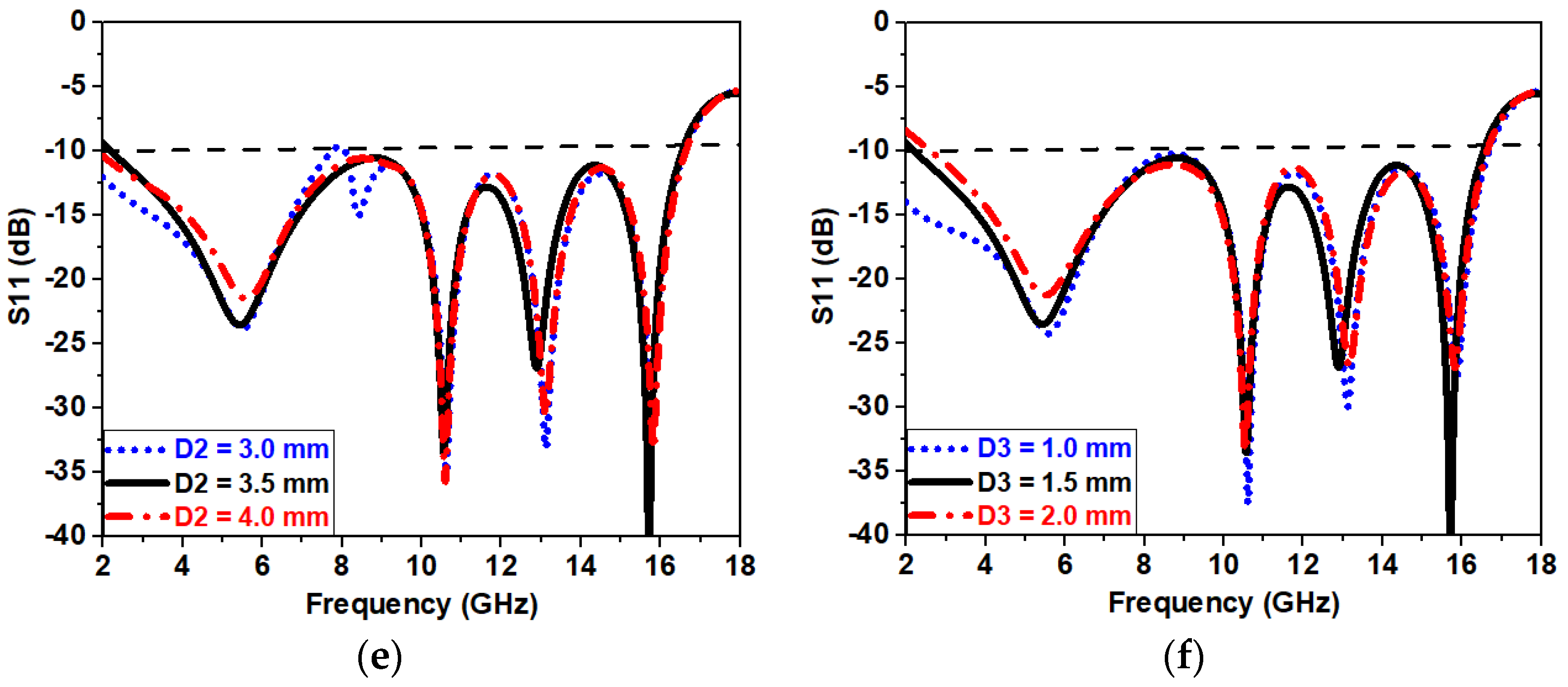
An additional crucial parameter that was assessed was the diameter of the asymmetric circular slot, denoted as D2, which was gradually modified in increments of 0.5 mm from 3 mm to 4 mm. The undesirable consequences seen when deviating from the D2 value of 3 mm were a decrease in impedance bandwidth and a displacement of the S11 curve beyond −10 dB, as illustrated in Figure 4e. As a result, the most suitable diameter for D2 was 3.5 mm, which effectively maintained the specified impedance characteristics and operational frequency range. The circular slot D3 etched on the curvature of the semicircle radiator was subjected to changes in the diameter in ±0.5 mm steps, ranging from 1 mm to 2 mm. The investigation revealed that D3 values of 1 mm and 2 mm had a detrimental effect on the S11 curves within the frequency range. As a result, it was discovered that D3 exhibited the highest level of effectiveness when its width was set at 1.5 mm, as depicted in Figure 3f.
In the final analysis, the extensive parametric study played a crucial role in optimizing the antenna layout. To ensure that the final antenna design met the specified operational frequency and radiation characteristics while retaining impedance bandwidth, it made it possible to identify the ideal values for parameters such as V1, V2, V3, Fw, D2, and D3. This ultimately contributed to the development of an effective UWB antenna construction.

4. Characteristic Mode Analysis

Characteristic mode analysis (CMA) is a highly effective technique utilized in the investigation of antennas, regardless of their particular shape or design. The CMA framework is a versatile tool that allows for a more profound understanding of the physical phenomena displayed by antennas. It facilitates a full examination, improvement, and even creation of these essential communication components. One of the most important features of computational electromagnetics (CEM) is its capability to provide insight into the complex behavior of antennas through the analysis of their eigen equivalences. The eigenvalues, which serve as representations of the distinct modes of current distribution on the conducting material of the antenna, are of paramount importance in comprehending the mechanism by which the antenna emits electromagnetic energy. Effective use of CMA usually starts with representing the total current on the conducting material of the antenna as a sum of these several modes. The process of decomposition is accomplished by computing an extended eigenvalue equation and its associated eigenvalues. The utilization of the Method of Moments impedance matrices is frequently employed for this objective, facilitating the disentanglement of current into its constituent modes. An essential part of CMA is the obtained eigenvalues, represented as λ (lambda). The eigenvalues play a crucial role in facilitating the examination and evaluation of the radiation characteristics of the antenna across various modes. Through the analysis of these eigenvalues, antenna engineers and researchers can acquire valuable insights regarding the behavior of the antenna across different scenarios, hence facilitating the optimization of its performance for specific applications. The primary objective of CMA is to provide antenna specialists with the ability to analyze and interpret the complex electromagnetic characteristics of antennas. This enables them to make well-informed design choices, improve performance, and develop a more comprehensive understanding of the functionality of these crucial components in various operational modes. Equation (4) [19] depicts the total current. Modal weight coefficients ( β i ) determine eigencurrents’ effects on the total current. The entire current creates the radiated electric field since each eigencurrent generates its own.
J = i = n N β i J i
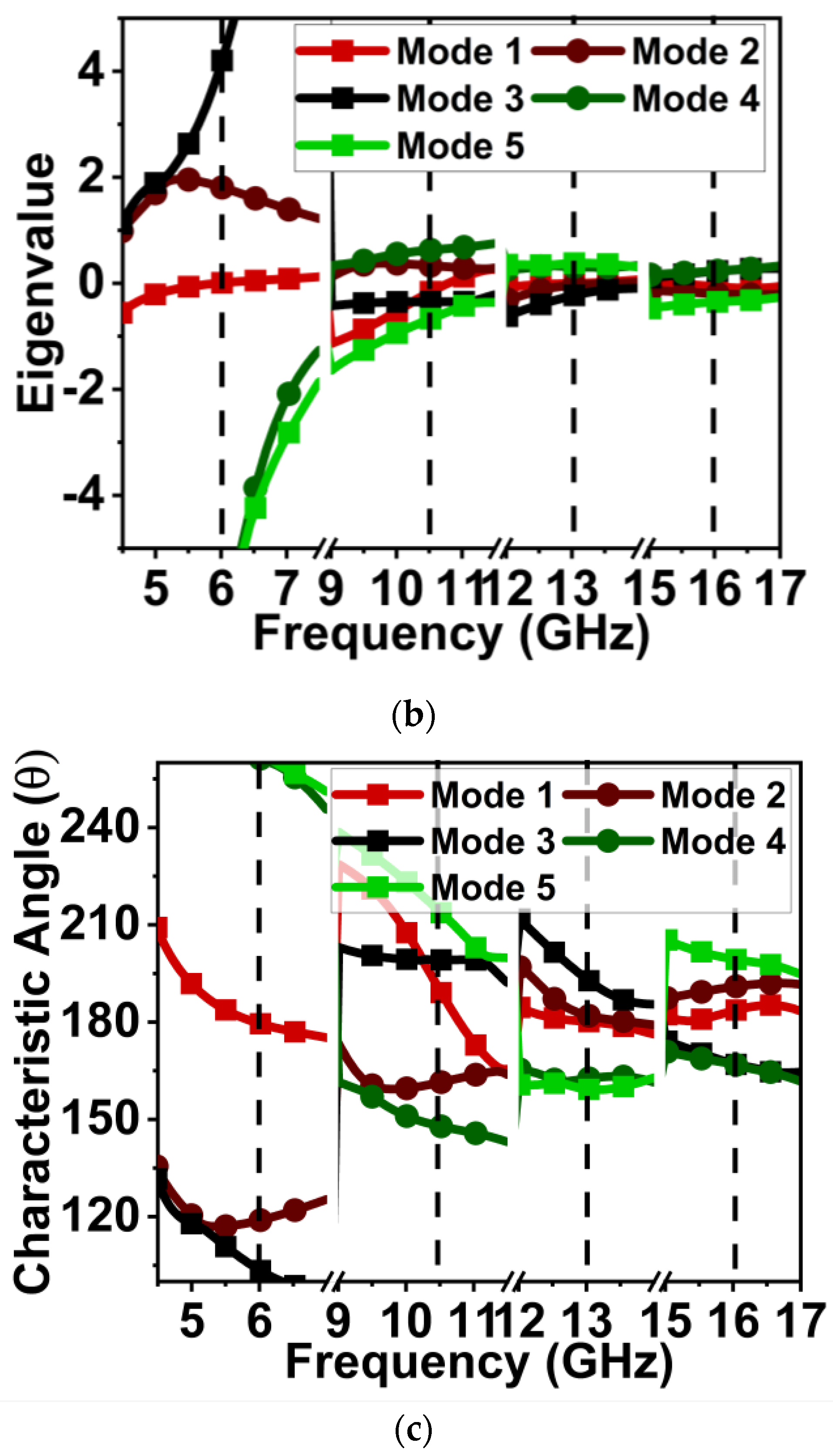
The key eigenvalue-based parameters crucial for our analysis include modal significance (MS) and the characteristic angle ( α n ) , as explicated in Equations (5) and (6) [20]. MS serves as a pivotal factor in discerning the significance of a mode, aiding in our assessment of its importance and understanding the characteristics of the stored mode or energy. This critical information can be found in Table 3, providing valuable insights into the significance of eigenvalues.
    M S = 1 1 + j λ n      
α n = 180 ° t a n 1 λ n
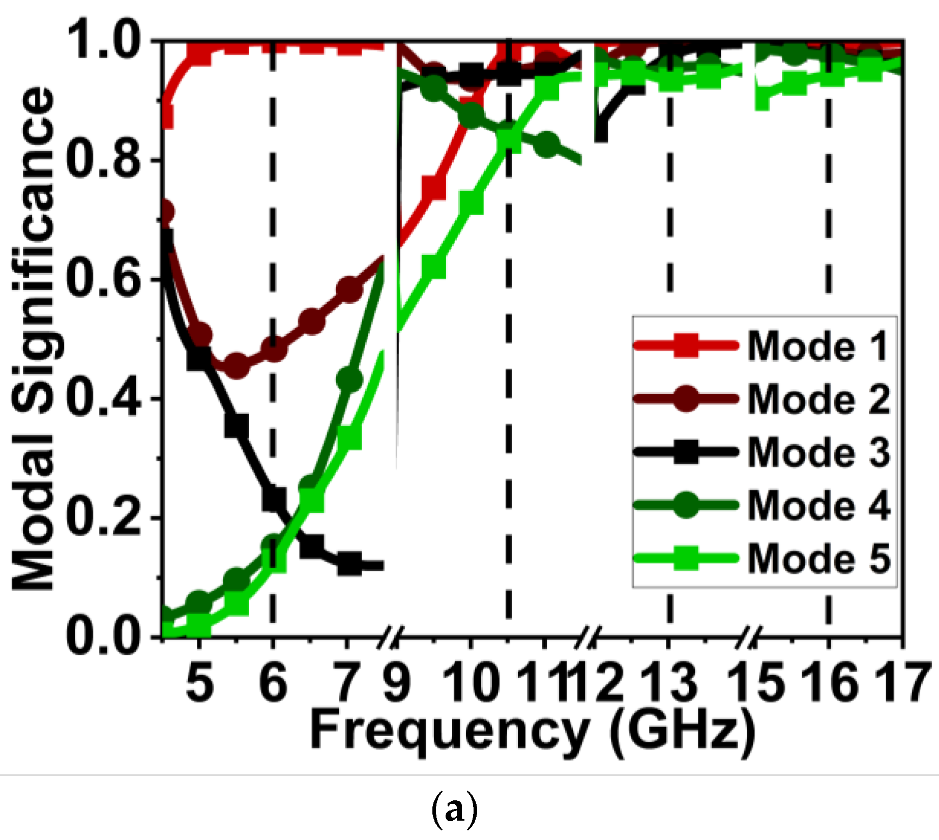
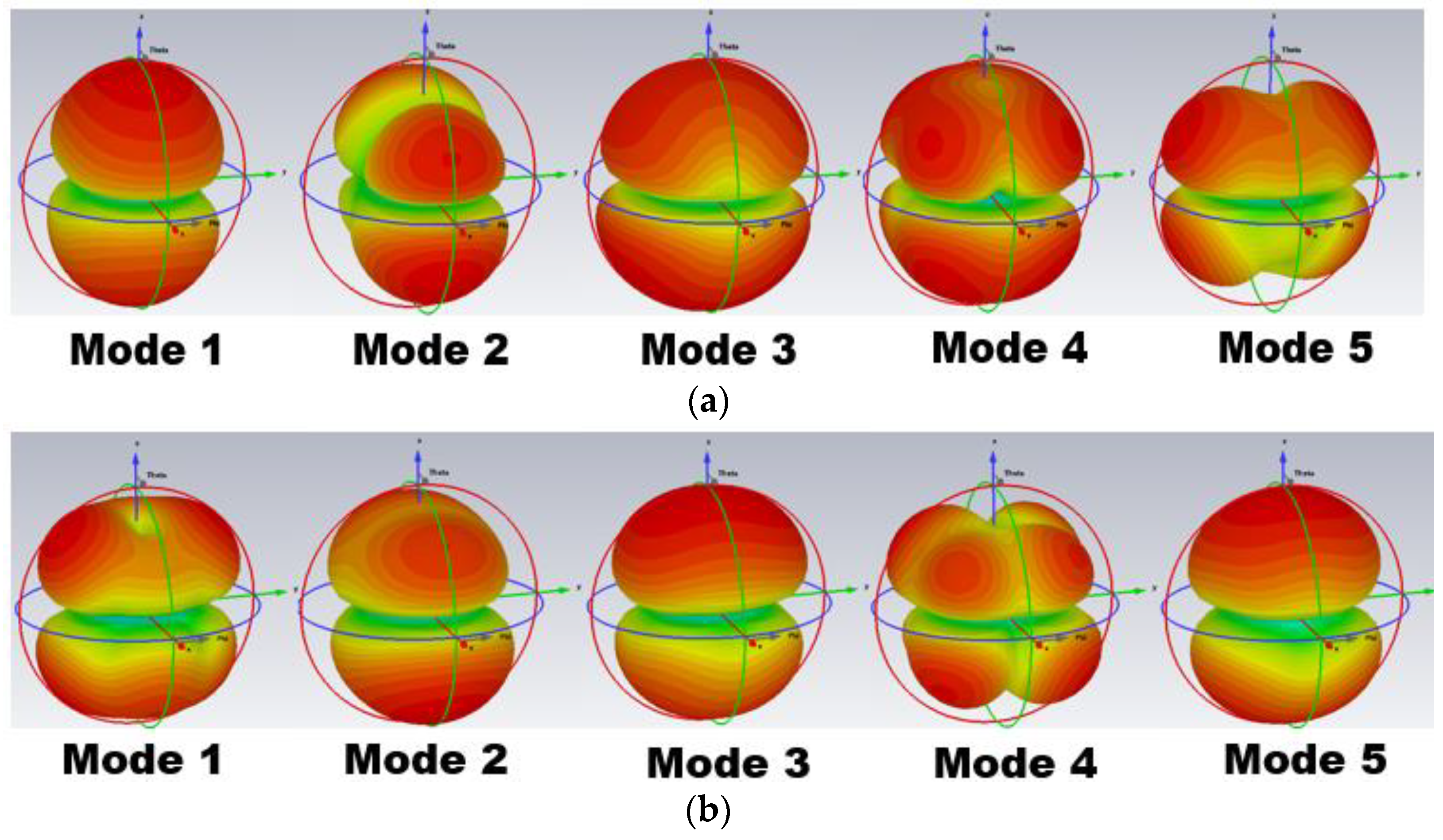
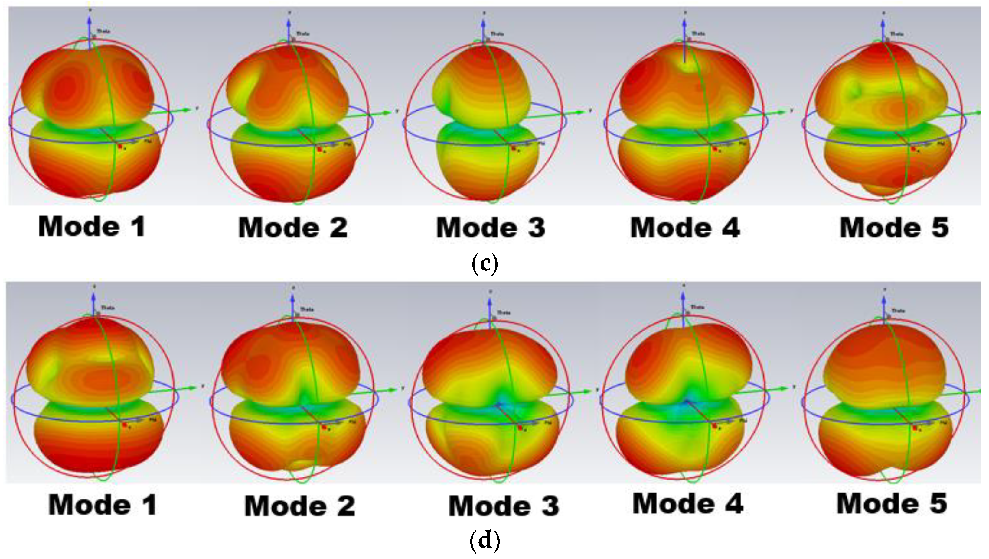
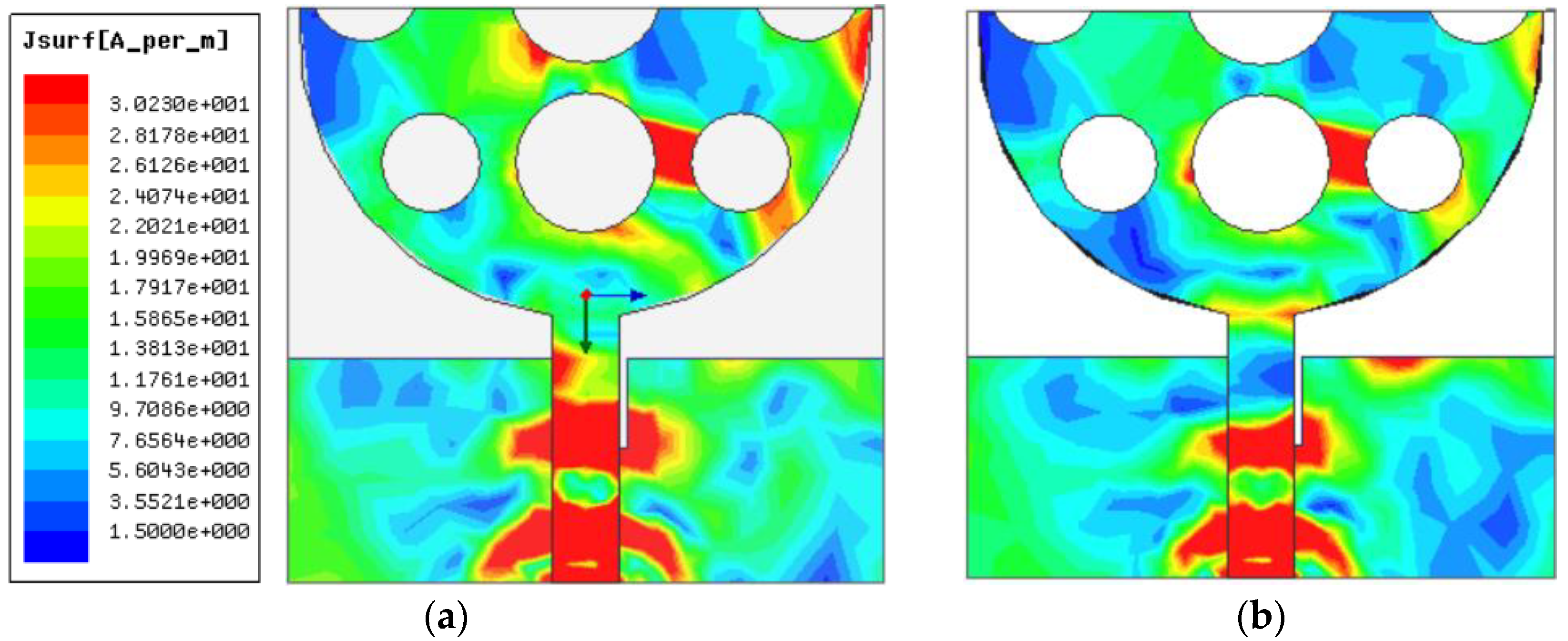
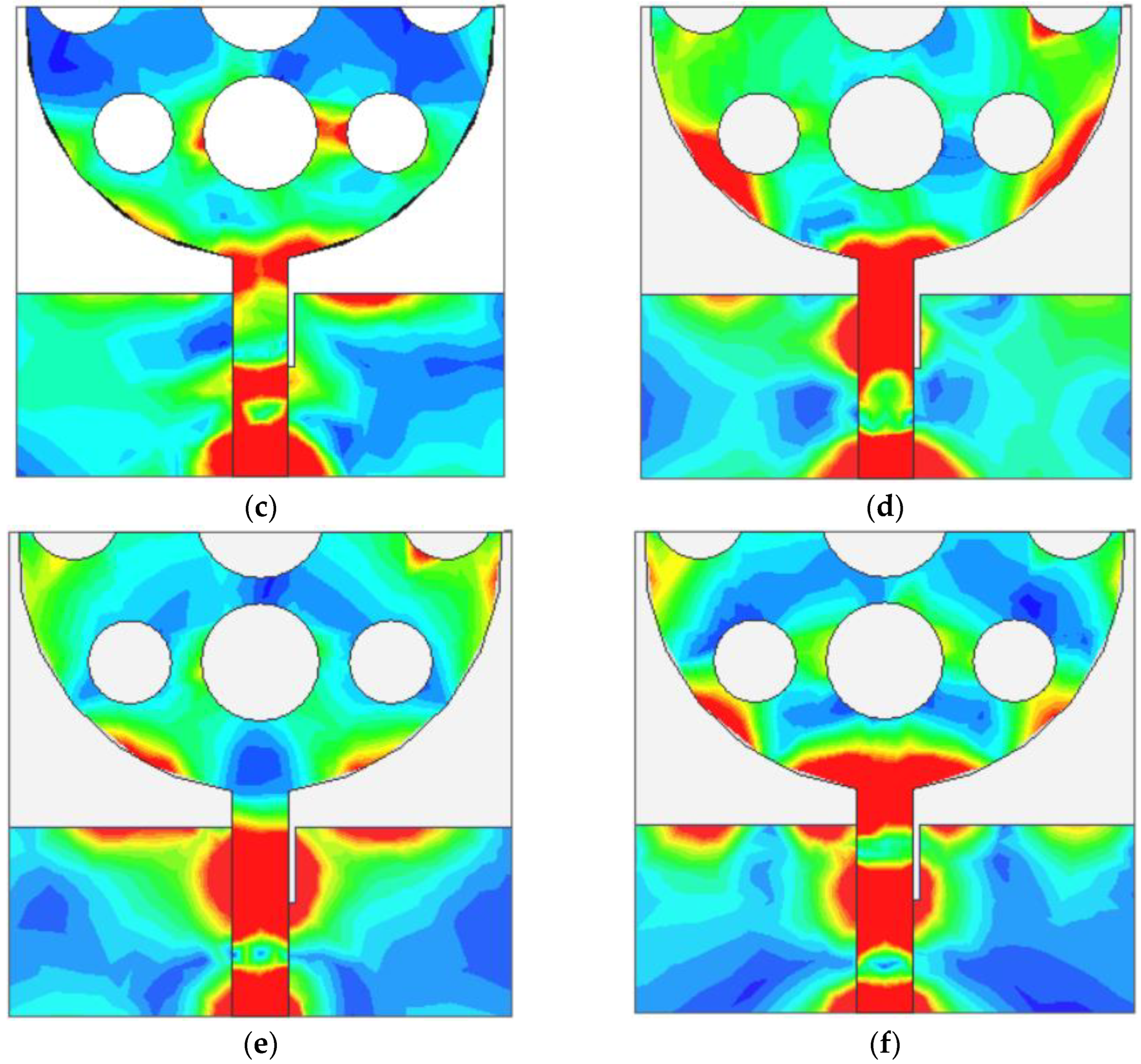
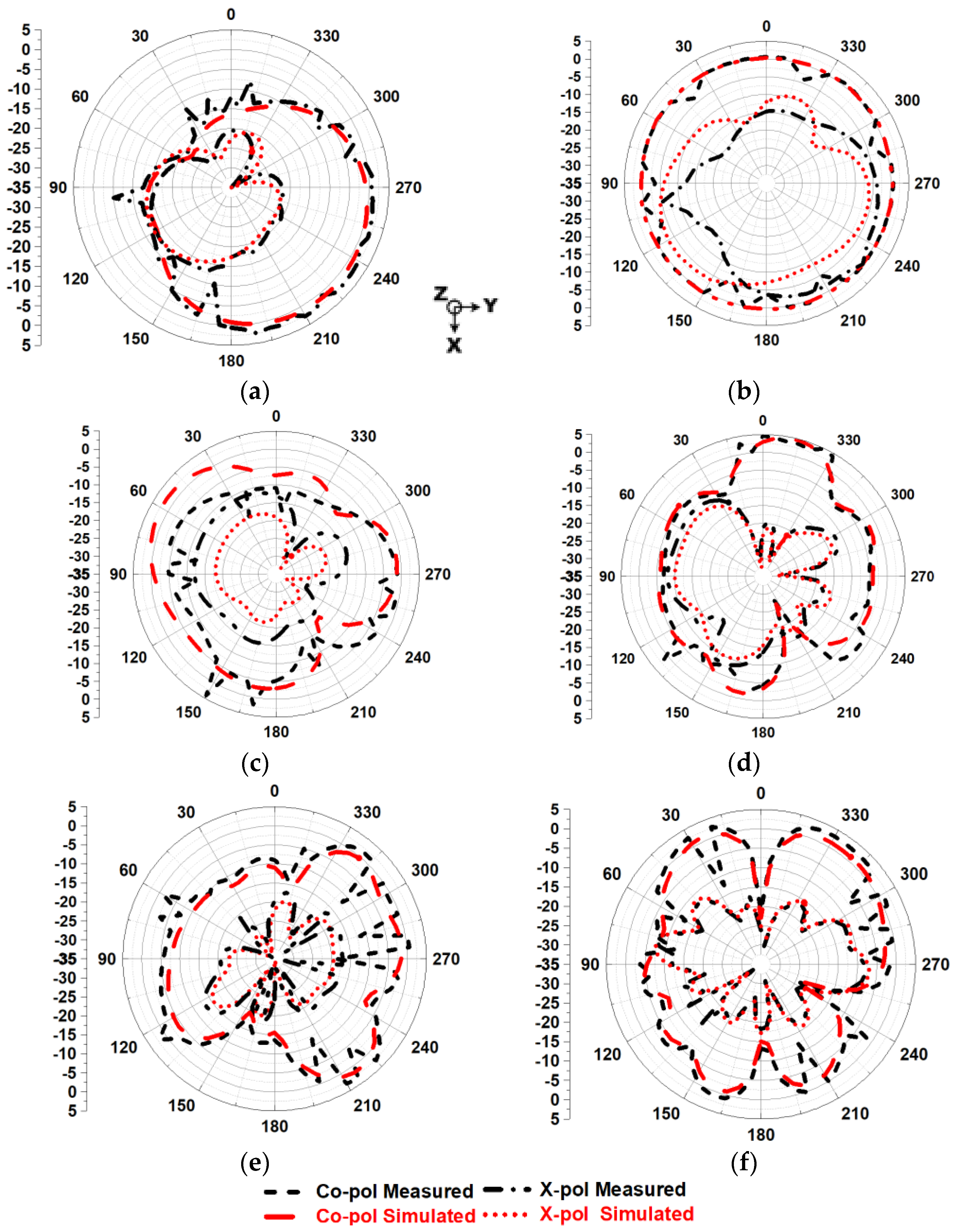
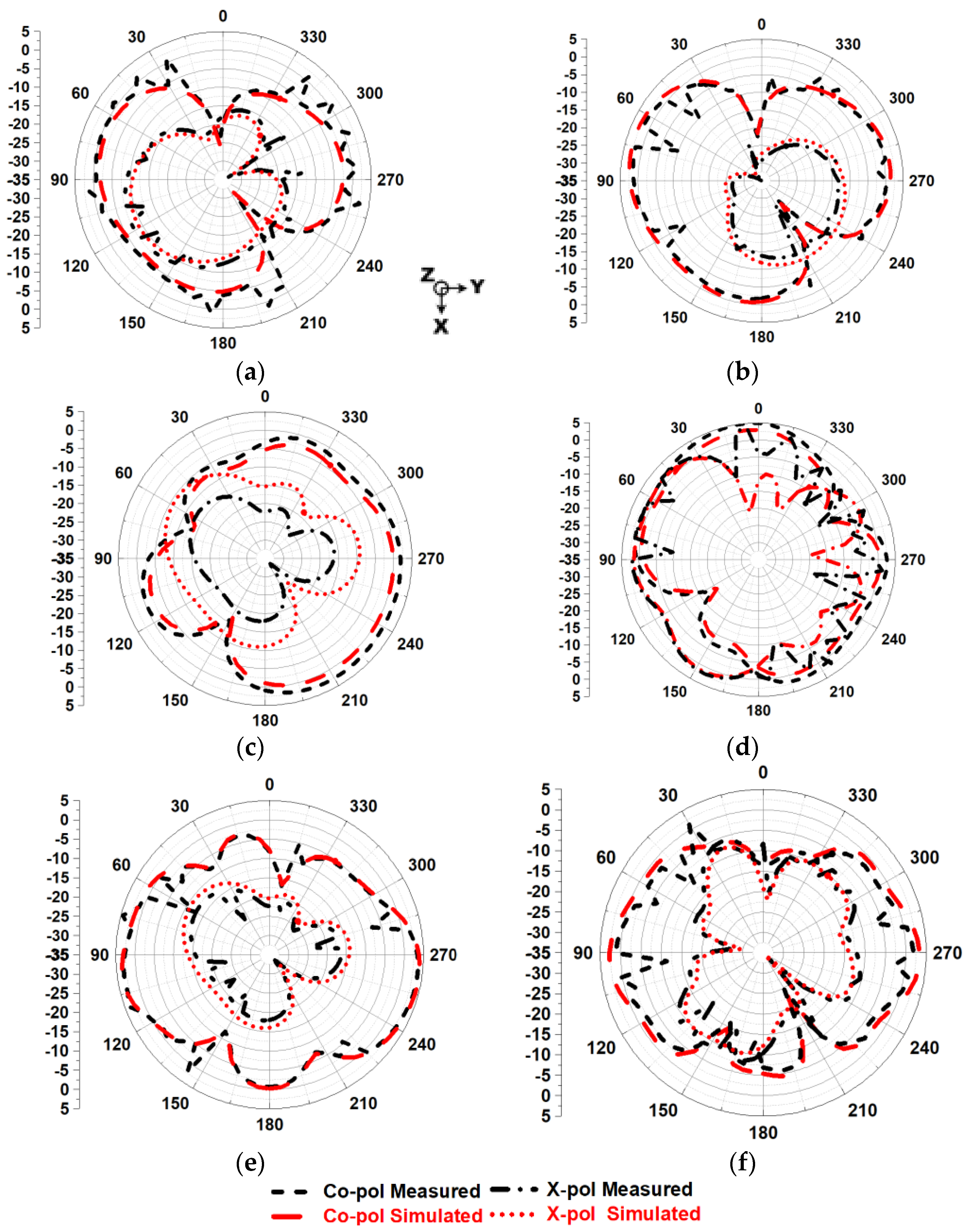
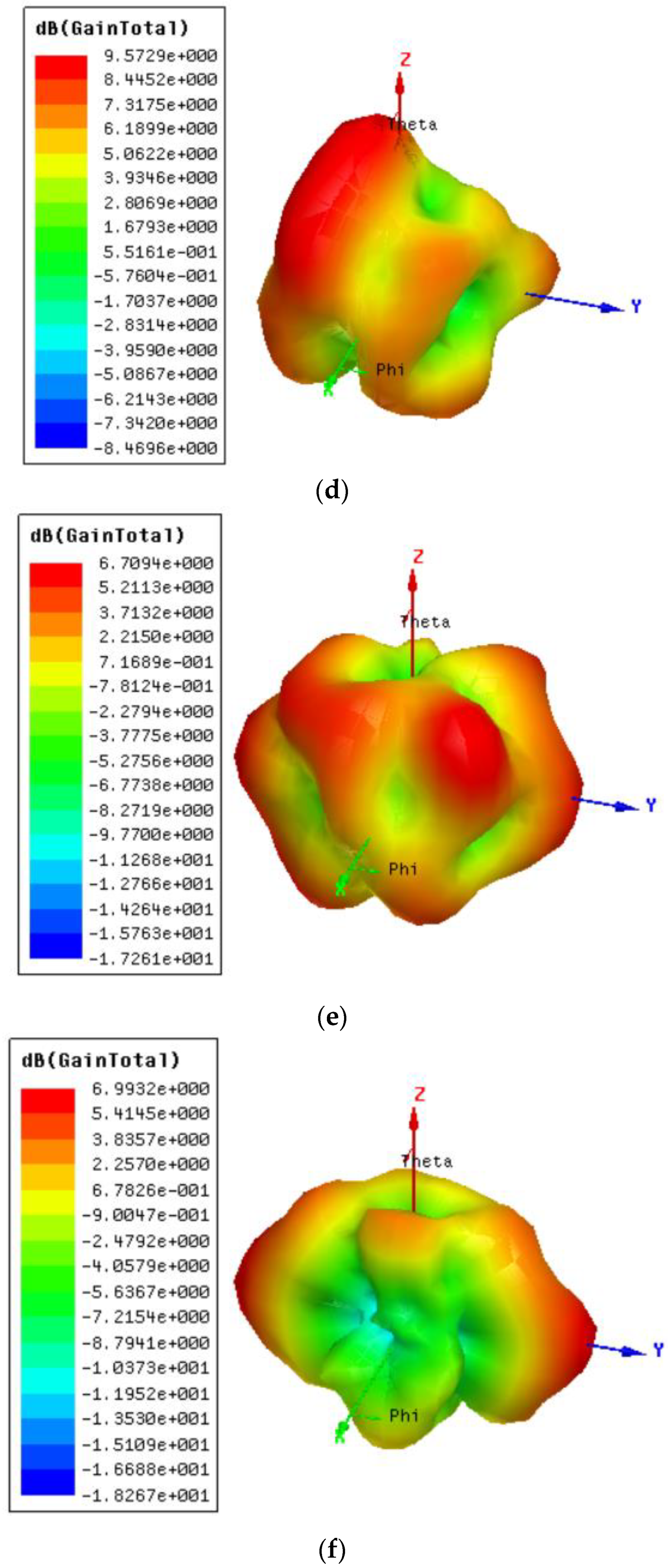
The CMA is applied to the proposed UWB antenna, wherein, in Figure 5 and Figure 6, it can be observed that the initial five modes of the designed antenna’s modal significance (MS) as well as its far-field characteristics.
The modes that resonate are indicated by an MS value of 1, while those modes lacking significance are denoted by MS values below 0.7. The MS is considered for four different resonance frequencies, i.e., 5.4, 10.56, 12.89, and 15.71 GHz. The entire CMA analysis of the proposed antenna is performed on the Computer Simulation Tool (CST) suite.

5. Results and Discussion

The UWB antenna was subjected to a thorough design process utilizing HFSS, a software tool known as High-Frequency Structure Simulator (HFSS). Subsequently, the antenna was physically fabricated on a substrate composed of FR-4 material, as illustrated in Figure 7a. To assess its performance and attributes, a series of experiments were carried out, with a specific emphasis on crucial factors such as S11, radiation properties, and time-domain analysis. Remarkable consistency was found when comparing the simulated findings with the real test results. The overall measurement setup to measure the parameters of the proposed antenna is depicted in Figure 7b,c. Nevertheless, slight deviations were noted, which can be ascribed to intrinsic discrepancies in the manufacturing process and the tolerances during testing. Minor variations such as these are frequently observed in real-world antenna development and do not have a substantial effect on the overall evaluation of the antenna’s effectiveness.

5.1. Scattering Parameters

Figure 8 shows the S11 curve of the planned UWB antenna in both modeling and real-world testing. This S11 performance is measured using a ZNB 40 vector network analyzer (100 KHz–40 GHz) from RHODE & SCHWARZ (Munich, Germany). The provided visual depiction effectively demonstrates the extensive range of impedance bandwidth shown by the antenna, which encompasses frequencies ranging from 2.2 to 16.5 GHz. The significant bandwidth observed in this case demonstrates an impressive fractional bandwidth of 152%, which highlights the antenna’s capacity to effectively function across a broad variety of frequencies. The UWB antenna’s success in achieving the specified performance criteria is affirmed by the rigorous design and testing methods, as well as the tight alignment between simulated and measured results. The antenna possesses a significant impedance bandwidth and fractional bandwidth, rendering it a desirable constituent for applications that require high-frequency data transmission and signal reception across a wide range of frequencies.

5.2. Current Distribution

The visual representation in Figure 9 illustrates the existing distribution within the UWB antenna at frequencies, specifically 2.5 GHz, 3.5 GHz, 5.4 GHz, 10.56 GHz, 12.89 GHz, and 15.71 GHz. The presented illustration of the present distribution provides significant insights into how electromagnetic energy propagates within the antenna structure at these pivotal frequencies. The graphic representation demonstrates that the feedline, which denotes the location where the electromagnetic signal is introduced into the antenna, has the most pronounced current density. This behavior is both anticipated and advantageous, as it indicates that the energy supplied to the antenna is well dispersed throughout the feedline, priming it for emission into the surrounding environment. Furthermore, it is worth noting that the central region of the antenna exhibits a significant accumulation of electric current. The present focus in the core region is crucial to guaranteeing optimal radiation properties. The design of the antenna effectively facilitates the guidance and radiation of electromagnetic energy from its central core, hence playing a significant role in determining its performance. In brief, the distribution plot depicted in Figure 9 provides empirical evidence that the UWB antenna is operating as anticipated at the specified resonant frequencies. The observed high concentration of electromagnetic signals in both the feedline and center region of the antenna confirms its effectiveness in efficiently capturing and radiating such signals. This characteristic renders the antenna a valuable component for various applications that operate at high frequencies.

5.3. Radiation Properties and Gain Analysis

The radiation pattern of the UWB (ultrawideband) antenna is measured in an anechoic chamber, as depicted in Figure 10. The pattern is analyzed for both the E-plane (electric field plane (along xz-plane)) and the H-plane (magnetic field plane (along yz-plane)) at two lower (i.e., 2.5 and 3.5 GHz) and four resonant frequencies (i.e., 5.4, 10.56, 12.89 and 15.71 GHz). The results of this examination are illustrated in Figure 11a–f and Figure 12a–f. The radiation pattern is a crucial indicator of how an antenna produces electromagnetic energy across various directions and polarizations. The radiation pattern diagram clearly illustrates a significant disparity in the co-polarization and cross-polarization properties of the antenna. The term “co-polarization” denotes the configuration in which the electric or magnetic field vectors of the emitted waves are parallel to those of the antenna. Conversely, “cross-polarization” indicates a scenario in which these vectors are orthogonal to each other. The differentiation between these two concepts is of utmost importance in comprehending how the antenna emits energy and engages with signals of varying polarizations. The antenna under consideration exhibits bidirectional and omnidirectional radiation characteristics in both the electric (E) and magnetic (H) planes. A bidirectional pattern indicates that the antenna primarily emits energy in two opposing directions, whereas an omnidirectional pattern indicates that the antenna uniformly emits energy in all directions around its axis. The capacity to transmit or receive signals in several directions is of great value in applications that necessitate flexibility.
As depicted in Figure 13a–f, the 3D-gain pattern of the proposed structure shows 3.45 dBi, 5.27 dBi, 4.48 dBi, 9.57 dBi, 6.70 dBi, and 6.99 dBi of gain observed at 2.5, 3.5, 5.4, 10.56, 12.89, and 15.71 GHz, respectively. As illustrated in Figure 13g, the antenna that has been constructed exhibits a consistent minimum gain of 3.45 dBi across its designated frequency range of operation. The continual increase in gain level observed in this context suggests that the antenna possesses a proficient capacity to emit electromagnetic energy efficiently and uphold signal strength within the designated frequency range. Also, the simulated radiation efficiency of the antenna is depicted in Figure 13g, wherein it can be seen that the antenna has an average efficiency greater than 80% throughout the impedance bandwidth.
In conclusion, the examination of the suggested UWB antenna’s radiation pattern demonstrates its ability to emit energy in many directions and polarizations. The bidirectional and omnidirectional properties of the device contribute to its adaptability across a range of applications. Furthermore, the consistent gain of the antenna across its operational frequency range highlights its appropriateness for meeting the demands of high-frequency data transmission and reception.

5.4. Time-Domain Properties

The analysis of the antenna in the time domain was deemed another crucial feature. Within the dominion of data transmission, ultrawideband (UWB) technology employs shorter pulses as a means of communication. Therefore, it is imperative to include an analysis in the time domain with the conventional frequency domain study. To evaluate the temporal characteristics of the antenna under consideration, a particular experimental arrangement was utilized. This arrangement entailed the placement of two identical antennas at a separation distance of 100 mm, both in side-to-side and face-to-face orientations, as depicted in Figure 14. Several essential time-domain properties were examined, as demonstrated in Figure 15.
One of the primary characteristics under consideration is isolation, which pertains to the extent of autonomy or segregation between the two antennas. The examination of isolation between antennas was conducted in both side-to-side and face-to-face configurations. The results demonstrate a noteworthy observation: The correlation between the antennas exhibits a significant level of isolation, exceeding 20 dB throughout the whole impedance spectrum in both designs. The observed high level of isolation in Figure 15a demonstrates the antennas’ capacity to operate autonomously and with minimal mutual interference, a critical factor for ensuring dependable data transmission. The term “group delay”, commonly abbreviated as GD, refers to the temporal displacement in phase concerning angular frequency. This parameter holds particular significance in applications where the timing of signals is of utmost importance. In this context, it was observed that the anticipated antenna’s group delay remained consistently below 1 nanosecond across its entire operational frequency spectrum, as illustrated in Figure 15b. The small group delay of this antenna highlights its capacity to transmit and receive signals without significant temporal distortion, rendering it highly suitable for applications that need accurate signal timing. The analysis of the antenna’s phase response in the time domain was deemed another crucial feature. The analysis of phase response offers valuable information about the degree of linearity shown by the antenna’s behavior. The UWB antenna under consideration demonstrated a linear phase response, as depicted in Figure 15c, which is advantageous for preserving signal integrity and reducing distortions during transmission. In brief, the examination of the suggested UWB antenna extended its scope beyond the frequency domain to incorporate the time domain, taking into account factors such as isolation, phase response, and group delay. The antenna exhibited significant isolation, a linear phase response, and little group delay, thereby confirming its appropriateness for applications that need both wide frequency coverage and accurate timing and signal integrity in data transmission and reception.

6. Comparative Analysis

The evaluation of the performance of the proposed UWB antenna has been conducted systematically, involving a comparison with previously reported antenna designs found in the existing literature. This comparative analysis offers vital insights into the performance characteristics of the new antenna in comparison to its predecessors. In order to enable this comparative analysis, the dimensions of the antenna have been denoted in relation to the wavelength (λ), a customary approach within the field of antenna engineering. The calculation of wavelength is based on the lower frequency of operation, which provides a consistent reference point for assessing the size and performance characteristics of the antenna.
The geometric characteristics of the planned antenna exhibit a close resemblance to those of previously documented designs, which are explicitly cited in references [13] and [14]. However, the distinguishing characteristic of the recently developed antenna lies in its remarkable accomplishment of possessing a wider impedance bandwidth and higher gain in comparison to the antennas discussed in references [13,14,15,17,21,22].
Table 4 presents a comprehensive overview of the performance measurements, showcasing the notable advantages of the developed antenna in comparison to its previous iterations. The newly developed antenna demonstrates an increased impedance bandwidth, suggesting its potential to function efficiently across a larger spectrum of frequencies. Furthermore, it exhibits a broader bandwidth, indicating its enhanced capacity to capture and transmit electromagnetic signals with increased efficacy. The comparative analysis highlights the progress achieved in antenna design through the introduction of the novel UWB antenna. The capability of providing a broader impedance bandwidth and enhanced gain makes it a promising contender for a range of applications, as compared to previous designs documented in existing literature.

7. Conclusions

The research presents a compact asymmetric circular slotted semi-circle-shaped extended ultrawideband antenna for wireless applications. The unique U-shaped truncated defective ground structure is used to improve the functional bandwidth up to 152%, which encompasses the frequency range of 2.2 to 16.5 GHz. The achievement of achieving a wide bandwidth is of great significance, as it allows the antenna to effectively encompass a diverse range of frequencies, rendering it appropriate for a large array of wireless communication applications. The designed UWB antenna’s performance characteristics, such as scattering parameters and radiation patterns observed at the resonant frequencies are found to be stable. The antenna exhibits the gain of at least 3.45 dBi across the entire impedance bandwidth and the maximum peak gain of 9.2 dBi achieved at the mid-resonance frequency of 10.5 GHz. CMA, and time-domain characteristics, are examined. The simulated and measured results are consistent. The overall results of this examination emphasize the suitability of the developed antenna configuration appropriate for wireless applications. The future direction of this work involves the utilization of this antenna in the form of an array-based multiple input multiple output (MIMO) antenna to further enhance its capacity. Also, to improve its gain at the lower band frequency, selective surfaces or metasurfaces could be employed.

Author Contributions

Conceptualization, S.B.K., R.C.B., T.A., V.K.J., S.S. and S.P.; methodology, S.B.K., R.C.B., T.A., V.K.J., S.S. and S.P.; software, S.B.K., R.C.B., T.A., V.K.J., S.S. and S.P.; validation, S.B.K., R.C.B., T.A. and S.P.; formal analysis, S.B.K., R.C.B., T.A., V.K.J., S.S. and S.P.; investigation, S.B.K., R.C.B., T.A., V.K.J. and S.P.; resources, S.B.K., R.C.B., T.A., V.K.J. and S.P.; data curation, S.B.K., R.C.B., T.A., V.K.J., S.S. and S.P.; writing—original draft preparation, S.B.K., R.C.B. and T.A.; writing—review and editing, S.B.K., R.C.B., T.A., V.K.J., S.S. and S.P.; visualization, S.B.K., R.C.B., T.A., V.K.J., S.S. and S.P.; supervision, R.C.B. and T.A. All authors have read and agreed to the published version of the manuscript.

Funding

This research received no external funding.

Data Availability Statement

The data are contained within the article.

Conflicts of Interest

The authors declare no conflict of interest.

References

  1. Devana, V.K.R.; Satyanarayana, V.; Lakshmi, A.V.; Sukanya, Y.; Kumar, C.M.; Ponnapalli, V.P.; Jagadeesh Babu, K. A novel compact fractal UWB antenna with dual band notched characteristics. Analog. Integr. Circuits Signal Process. 2019, 110, 349–360. [Google Scholar] [CrossRef]
  2. Galvan-Tejada, G.M.; Peyrot-Solis, M.A.; Aguilar, H.J. Ultra Wideband Antennas: Design, Methodologies, and Performance; CRC Press: Boca Raton, FL, USA, 2017. [Google Scholar]
  3. Revision of part 15 of the communication’s rules regarding ultra-wideband transmission systems, Federal communications commission. ET-Docke 2002, 98–153, FCC-02-48.
  4. Pandhare, R.A.; Abegaonkar, M.P.; Dhote, C. UWB antenna with novel FSS reflector for the enhancement of the gain and bandwidth. Int. J. Microw. Wirel. Technol. 2022, 14, 1353–1368. [Google Scholar] [CrossRef]
  5. Uwiringiyimana, J.P.; Khayam, U.; Montanari, G.C. Design and implementation of ultra-wide band antenna for partial discharge detection in high voltage power equipment. IEEE Access 2022, 10, 10983–10994. [Google Scholar] [CrossRef]
  6. Sang, L.; Wang, J.; Liu, Z.; Wang, W.; Huang, W.; Tu, H. A UWB Metal Waveguide Slot Array Antenna Based on Hybrid Resonant Structural Components. IEEE Antennas Wirel. Propag. Lett. 2022, 22, 923–927. [Google Scholar] [CrossRef]
  7. Nie, L.Y.; Lin, X.Q.; Xiang, S.; Wang, B.; Xiao, L.; Ye, J.Y. High-isolation two-port UWB antenna based on shared structure. IEEE Trans. Antennas Propag. 2020, 68, 8186–8191. [Google Scholar] [CrossRef]
  8. Naktong, W.; Ruengwaree, A. Four-port rectangular monopole antenna for UWB-MIMO applications. Prog. Electromagn. Res. B 2020, 87, 19–38. [Google Scholar] [CrossRef]
  9. Mahfuz, M.H.; Islam, M.R.; Habaebi, M.H.; Sakib, N.; Hossain, A.Z. A notched UWB microstrip patch antenna for 5G lower and FSS bands. Microw. Opt. Technol. Lett. 2022, 64, 796–802. [Google Scholar] [CrossRef]
  10. Abbas, A.; Hussain, N.; Sufian, M.A.; Jung, J.; Park, S.M.; Kim, N. Isolation and gain improvement of a rectangular notch UWB-MIMO antenna. Sensors 2022, 22, 1460. [Google Scholar] [CrossRef] [PubMed]
  11. Saleh, S.; Ismail, W.; Abidin IS, Z.; Bataineh, M.H.; Al-Zoubi, A.S. Novel Compact UWB Vivaldi Nonuniform Slot Antenna with Enhanced Bandwidth. IEEE Trans. Antennas Propag. 2022, 70, 6592–6603. [Google Scholar] [CrossRef]
  12. Cheng, Y.; Dong, Y. Ultrawideband Shared-Aperture Crossed Tapered Slot Antenna for 5G Applications. IEEE Antennas Wirel. Propag. Lett. 2022, 22, 472–476. [Google Scholar] [CrossRef]
  13. Zaidi, A.; Awan, W.A.; Ghaffar, A.; Alzaidi, M.S.; Alsharef, M.; Elkamchouchi, D.H.; Alharbi, T.E. A low profile ultra-wideband antenna with reconfigurable notch band characteristics for smart electronic systems. Micromachines 2022, 13, 1803. [Google Scholar] [CrossRef] [PubMed]
  14. Kaur, K.; Kumar, A.; Sharma, N. Sprocket gear wheel shaped printed monopole ultra-wideband antenna with band notch characteristics: Design and measurement. Int. J. RF Microw. Comput.-Aided Eng. 2022, 32, e22989. [Google Scholar] [CrossRef]
  15. Kumar, P.; Ali, T.; Mm, M.P. Characteristic mode analysis-based compact dual band-notched UWB MIMO antenna loaded with neutralization line. Micromachines 2022, 13, 1599. [Google Scholar] [CrossRef] [PubMed]
  16. Ahmad, S.; Ijaz, U.; Naseer, S.; Ghaffar, A.; Qasim, M.A.; Abrar, F.; Abd-Alhameed, R. A jug-shaped CPW-fed ultra-wideband printed monopole antenna for wireless communications networks. Appl. Sci. 2022, 12, 821. [Google Scholar] [CrossRef]
  17. Khan, M.A.; Rafique, U.; Savci H, Ş.; Nordin, A.N.; Kiani, S.H.; Abbas, S.M. Ultra-wideband pentagonal fractal antenna with stable radiation characteristics for microwave imaging applications. Electronics 2022, 11, 2061. [Google Scholar] [CrossRef]
  18. Balanis, C.A. Antenna Theory: Analysis and Design; John Wiley & Sons: Hoboken, NJ, USA, 2016. [Google Scholar]
  19. Harrington, R.; Mautz, J. Theory of characteristic modes for conducting bodies. IEEE Trans. Antennas Propag. 1971, 19, 622–628. [Google Scholar] [CrossRef]
  20. Han, M.; Dou, W. Compact clock-shaped broadband circularly polarized antenna based on characteristic mode analysis. IEEE Access 2019, 7, 159952–159959. [Google Scholar] [CrossRef]
  21. Subhash, B.K.; Kumar, P.; Pathan, S.; Ali, T.; Biradar, R.C. A Sequence of Circular Slotted Nonagon Shape Extended Ultrawideband Antenna for Smart Electronic Systems using Characteristic Mode Analysis. In Proceedings of the 2023 International Telecommunications Conference (ITC-Egypt), Alexandria, Egypt, 18–20 July 2023; pp. 12–16. [Google Scholar]
  22. Alharbi, K.H.; Moniruzzaman, M.; Aldhaheri, R.W.; Aljohani, A.J.; Singh, S.; Samsuzzaman, M.; Islam, M.T. Ultra-wideband monopole antenna with U and L shaped slotted patch for applications in 5G and short distance wireless communications. Int. J. Appl. Electromagn. Mech. 2021, 66, 159–180. [Google Scholar] [CrossRef]
Figure 1. The evolution phases of the (a) UWB antenna and (b) their S11 curve.
Designs 07 00141 g001aDesigns 07 00141 g001b
Figure 2. Detailed geometric information of the antenna.
Designs 07 00141 g002
Figure 3. Proposed UWB antenna (a) equivalent circuit and (b) compared simulated HFSS and equivalent circuit S11.
Designs 07 00141 g003
Figure 4. Parametric analysis (a) V4, (b) V3, (c) V1, (d) Fw, (e) D2 and (f) D3.
Designs 07 00141 g004aDesigns 07 00141 g004b
Figure 5. Characteristic mode analysis of the proposed UWB antenna (a) mode significance (b) eigenvalue (c) characteristic angle.
Designs 07 00141 g005aDesigns 07 00141 g005b
Figure 6. Far field pattern at (a) 5.4 GHz, (b) 10.56 GHz, (c) 12.89 GHz, and (d) 15.71 GHz.
Designs 07 00141 g006aDesigns 07 00141 g006b
Figure 7. Proposed UWB antenna (a) fabricated prototype showing front and ground part and (b) measurement set-up block diagram for measuring S11 parameter, and (c) measurement set-up block diagram for measuring radiation properties.
Designs 07 00141 g007aDesigns 07 00141 g007b
Figure 8. The S11 curve of the UWB antenna. Blue dot is line representing −10 dB threshold.
Designs 07 00141 g008
Figure 9. Current distribution (a) 2.5 GHz, (b) 3.5 GHz, (c) 5.4 GHz, (d) 10.56 GHz, (e) 12.89 GHz, and (f) 15.71 GHz.
Designs 07 00141 g009aDesigns 07 00141 g009b
Figure 10. Placement of proposed UWB antenna in an anechoic chamber for radiation pattern measurement.
Designs 07 00141 g010
Figure 11. E-plane pattern at (a) 2.5 GHz, (b) 3.5 GHz, (c) 5.4 GHz, (d) 10.56 GHz, (e) 12.89 GHz, and (f) 15.71 GHz.
Designs 07 00141 g011
Figure 12. H-plane pattern at (a) 2.5 GHz, (b) 3.5 GHz, (c) 5.4 GHz, (d) 10.56 GHz, (e) 12.89 GHz, and (f) 15.71 GHz.
Designs 07 00141 g012
Figure 13. 3D-gain plot at (a) 2.5 GHz, (b) 3.5 GHz, (c) 5.4 GHz, (d) 10.56 GHz, (e) 12.89 GHz, (f) 15.71 GHz, and (g) gain and efficiency vs. frequency curve.
Designs 07 00141 g013aDesigns 07 00141 g013bDesigns 07 00141 g013c
Figure 14. Time-domain characteristics. (a) Face-to-face; (b) side-to-side.
Designs 07 00141 g014
Figure 15. Time-domain features of the UWB antenna (a) isolation, (b) group delay, and (c) phase response.
Designs 07 00141 g015
Table 1. Detailed geometric layout (in mm).
W = 21.6L = 20.8Fw = 2.4FL = 9.6D1 = 5C2 = 3.5
D2 = 3.5D3 = 1.5V1 = 8.1V2 = 9.8V3 = 3.2V4 = 2.5
Table 2. Lumped parameters (R, L, C) values of equivalent circuit.
Inductance (L) (nH)Capactiance (C) (pF)Resistance (R) (Ω)
L1 = 0.44C1 = 1.68R1 = 68.35
L2 = 0.20C2 = 1.44R2 = 22.20
L3 = 0.11C3 = 0.88R3 = 739.20
L4 = 0.12C4 = 0.60R4 = 457.20
L5 = 2.84C5 = 0.13R5 = 72.50
L6 = 0.60C6 = 0.19R6 = 425.30
L7 = 0.48C7 = 0.41R7 = 218.50
L8 = 0.25 RL = 50
Table 3. Significance of eigenvalues.
Eigenvalues ( λ i )CA ( α i )Significance
λ i < 0 180 < α i < 270 Electric energy
λ i = 0 α i = 180 Resonating point
λ i > 0 90 < α i < 180 Magnetic energy
Table 4. Comparative analysis of the proposed antenna.
RefDesign
Techniques
Dimension
3)
Fractional Bandwidth (%)B.W
(GHz)
[13]Integrated slots onto radiator0.07 × 0.23 × 0.0151073–10
[14]Sprocket gear shape0.18 × 0.15 × 0.011422–12
[15]CPW and parasitic elements0.25 × 0.22 × 0.0161143–11
[17]Fractal based0.24 × 0.3 × 0.0071233–12.7
[21]Slots onto radiator and DGS0.3 × 0.26 × 0.0081403–17.2
[22]Rectangular patch with truncated corners0.3 × 0.19 × 0.0161242.8–12
Prop.Asymmetric slots onto
radiator and truncated DGS
0.21 × 0.2 × 0.0161522.2–16.5
Disclaimer/Publisher’s Note: The statements, opinions and data contained in all publications are solely those of the individual author(s) and contributor(s) and not of MDPI and/or the editor(s). MDPI and/or the editor(s) disclaim responsibility for any injury to people or property resulting from any ideas, methods, instructions or products referred to in the content.

