Article

An Integrated QFD and TRIZ Methodology for Innovative Product Design

by
Abdullah Al-Dwairi
1,
Omar Al-Araidah
1 and
Sa’d Hamasha
1,2,*
1
Department of Industrial Engineering, Jordan University of Science and Technology, Irbid 22110, Jordan
2
Department of Industrial and Systems Engineering, Auburn University, Auburn, AL 36849, USA
*
Author to whom correspondence should be addressed.
Designs 2023, 7(6), 132; https://doi.org/10.3390/designs7060132
Submission received: 20 September 2023 / Revised: 28 October 2023 / Accepted: 14 November 2023 / Published: 16 November 2023

Abstract

:
The paper presents a methodology that integrates Quality-Function Deployment (QFD) and the Theory of Inventive Problem Solving (TRIZ) used for generating innovative solutions to design problems. It proposes a modified analytical House of Quality (HoQ) to reveal and prioritize contradictions between design parameters and between customer requirements. The proposed methodology extends the traditional HoQ and eliminates the need for the TRIZ’s Function Analysis (FA) procedure. Function Analysis involves identifying the functions of a product or process elements and trying to find contradictions between the system elements. The usability of the proposed method is illustrated through the redesign of an assembly workshop to overcome major problems addressed by the various stakeholders of the process. The new design of the assembly workshop helps reduce the number of work stages from 3 to 1, reduce the number of workers from 4 to 2, decrease rework, decrease the percentage of damaged products, enhance workplace ergonomics and improve the overall system efficiency.
Keywords:
TRIZ; QFD; product design

1. Introduction

These days, the design process is a complex multi-dimensional process that may vary considerably with the product or process being designed. The design process has evolved over the past 200 years, starting from one person designing and manufacturing a simple product, such as a wooden chair, to multi-organization efforts designing a complex and complicated product [1]. The improvement in the design process over the years helped the designers to overcome complex challenges in modern product realization, such as the development of new creative product functions. The quality of design can be measured by the ability of the designer to translate customer(s) requirements to design parameters and characteristics that shape product features and specifications [2,3,4]. Over the years, designers used Quality Function Deployment (QFD) to organize the design development process. Moreover, many designers conduct functional analysis utilizing the Altshuller’s Theory of Inventive Problem Solving (TRIZ) innovation principles of problem solving to overcome design contradictions and to develop resolution alternatives [2,5]. The many toolkits of TRIZ are widely used today in the development and design of products, services, and business processes. Therefore, integrating QFD and TRIZ can result in a more useful design methodology with added advantages.
QFD is a design decision making process that aims to enhance quality assurance that allows for comparison against competitors and reducing development time and cost [6]. QFD is a systematic customer-driven technique used in a wide variety of industries to link customer requirements to design specifications and design targets using the House of Quality (HoQ) as a primary tool for mapping and analyzing requirements and design targets [2,3,4]. A traditional QFD consists of 8 steps to build the HoQ matrix. As a result, HoQ presents a correlation summary of design requirements, parameters, benchmarks, target measures, and technical difficulties. QFD was first introduced in the 1960s, was first utilized in 1972 [7], and since then has been widely used in industry worldwide. Min and Kim [8] introduced a time dimension into customer requirements to consider the longitudinal effect on customer requirements and the timing of their selection. Kwong and Chen [9] presented a fuzzy QFD model to correlate customer requirements and engineering characteristics. Chen and Weng [10] used fuzzy logic to measure the levels of fulfillment of each customer requirement in QFD, considering capacity and market constraints. Hana and Kimb [11] utilized linear partial ordering to account for incomplete information in prioritizing engineering characteristics in QFD. Lai and Xie [12] integrated competitors’ information in their method for ranking customer requirements. Delice and Gungor [13] combined mixed integer linear programming and Kano model for QFD-based optimization of solutions. Zheng and Chin [14] integrated QFD and process capability index for process elements in an optimization model for process quality planning taking into consideration technical, time, and cost constraints.
TRIZ is a structured problem-solving approach that builds on the idea that similar problems were faced and solved by others before. Therefore, a designer can systematically utilize TRIZ solution patterns in solving elements of encountered problems [5]. Problem solvers, including designers and inventors, can rely on TRIZ patterns to solve problems creatively and reduce development time [15]. Initially, the TRIZ database of solution patterns of evolution was realized by Genrich Altshuller through his study of 40,000 engineering systems and technologies patents [5]. Today, over 2.5 million patents are included in the TRIZ database with various toolkits for inventive problem solving [2]. TRIZ involves seven main concepts and tools, which are the concept of Contradictions, the concept of Resources, the concept of Ideal Final Result (IFR), the Patterns of Evolution, the Standard Solutions, Algorithm of Inventive-Problem Solving (ARIZ), and the 40 Inventive principles and contradiction matrix. The most widely used concept is that of the 40 inventive principles utilized with the contradiction matrix. Table 1 shows the list of the 40 inventive principles used for finding a concept for a solution, and the TRIZ typical standard features of the Contradiction Matrix [2,16,17,18]. Tong, Cong, and Lixiang [19] presented a patent classification to help TRIZ users identify related patents based on TRIZ principles. Chang and Chen [20] presented an eco-innovative design tool, which consolidates TRIZ and uses the contradiction matrix to assist designers in making related decisions. Kim [21] modified a TRIZ based process design procedure to enhance safety in the design of chemical processes, considering the various process parameters. Robles, Negny, and Lann [22,23] integrated Case-Based Reasoning and TRIZ to reduce design effort and time in chemical engineering. One of the recent developments of TRIZ includes the formulation and prioritization the functional requirements. Russo and Spreafico [24] proposed a multilevel login method using functional structure analysis to develop design solutions using TRIZ principles.
Several researchers integrated QFD and TRIZ to utilize the advantages of both techniques and accelerate the design process. Li et al. [25] proposed a three-phase QFD and TRIZ methodology to enhance the interaction between alarm systems and operators. The authors applied QFD to identify design parameters, the parameters are then translated to standard TRIZ features, and finally, the contradiction matrix is used to resolve contradictions. Frizziero et al. [26] and Caligiana et al. [27] developed strategies based on QFD and TRIZ analysis for the validation of a methodology for the design for hybrid manufacturing applied to direct open molds. Naveiro and Oliveira [28] used TRIZ and QFD to build a model to optimize design parameters during concept development systematically. Donnici et al. [29] used combined TRIZ, QFD, and Six Sigma for an innovative design approach. They applied the proposed method to reduce the impact of cigarette butts on the environment. Lyu et al. [30] proposed a hybrid approach integrating QFD with the Kano model to define consumer requirements and improve market competitiveness. Carneiro et al. [31] integrated QFD and fuzzy logic for product development. Their approach was applied to the product development of AGV structures. The proposed model starts by surveying published patents that relate to the design required. Related design parameters and the corresponding customer requirements are then extracted from the patent documents, and customers are asked to weigh the closeness of their requirements to the ones extracted. The HoQ is then used to identify the relationships between the various requirements and parameters, and TRIZ is used to resolve revealed contradictions. Positive scores are given to design parameters and features that, if integrated to conceptual design, would increase customer satisfaction. The resulting conceptual design will have to-date technical features with minimal contradictions. Wang [32] used an integrated QFD, TRIZ, and Analytic Hierarchy Process (AHP) model to improve the design of smartphones to satisfy the various requirements of users. The author introduced several examples to validate their findings. Francia et al. [33] integrated QFD and TRIZ into computer aided drafting in their project PrinterCAD. The study targeted applying additive and subtractive techniques in open molding design and manufacturing using 3D printing. Wang, Lee, and Trappey [34] integrated QFD, TRIZ, and service blueprint approaches in a cloud-based production service concept applied to meal services. The proposed intelligent structure aimed to improve the performance of service originations. Vinodh, Kamala, and Jayakrishna [35] used environmentally conscious quality function deployment (ECQFD), TRIZ, and AHP in the development of automotive parts. Zhang, Yang, and Liu [36] proposed a 4-step model, customer satisfaction needs (CSNs), QFD, TRIZ, and fuzzy logic model, for ergonomic design and evaluation. The model is applied to the innovative design and evaluation of kitchen stoves. Kim and Yoon [37] presented a QFD and TRIZ based approach to resolve contradictions between the product and service components in a product-service system (PSS). Wang et al. [38] developed a software tool, TRIZ matrix, based on their proposed algorithm to integrate QFD and TRIZ. The authors demonstrated the usability of the software through a case study addressing the airbag design problem. Yamashina, Ito, and Kawada [39] proposed a method, Innovative Product Development Process (IPDP), to integrate QFD with TRIZ. The hierarchical structure of IPDP reveals the function or mechanism in a product that requires most technical innovation based on customer requirements, and contradictions are then identified and resolved by applying TRIZ.

2. Integrating QFD and TRIZ Method

The modified HoQ facilitates the integration of QFD and TRIZ through the identification of aggregated importance values for design parameters based on customer requirements. Moreover, it incorporates technical contradictions from the HoQ to facilitate their resolution through TRIZ innovation principles. Figure 1 shows the 9 rooms of the proposed HoQ incorporating 9 steps of development, and Figure 2 illustrates the modified HoQ with all notations.
Step 1. Identify customers (Who): Customers or customer groups Cn (n = 1, 2, …, N) are identified. Using Likert scale, each Cn is assigned an absolute or relative weight WCn based on their demand on the product, and weights are then normalized accordingly.
Step 2. Determine customer requirements (What): Utilize alternative methods to survey customer requirements Ri (i = 1, 2, …, I).
Step 3. Determine importance of customer requirements (Who vs. What): Using Likert scale, customers may rate the absolute or relative importance of their requirements. Let min be the weight that customer Cn assigned to requirement Ri, the total adjusted weight assigned to requirement Ri by all customers equals M R i = n N m i n W C n , and the normalized weight of requirement Ri can then be computed as W R i = M R i / i I M R i .
Step 4. Benchmarking (Now): Identify competing products (Now) and determine how customers perceive the competition ability to meet each requirement (Now vs. what). Let Hk (k = 1, 2, …, K) represents competing products, customers assess each product Hk for each requirement Ri using Likert scale as weight sik. The total weight for Hk for all requirements Ri can then be given by S D k = i I s i k W R i .
Step 5. Generate design specifications (How): Measurable design specifications and parameters, Pj (j = 1, 2, …, J), are developed in correlation with each customer requirement Ri. The generated specifications represent a translation of the requirements to a design problem with each design parameter having a target direction of improvement; to maximize (↑) or to minimize (↓), and a met target is denoted by (↕).
Step 6. Relate customer requirements to design parameters (What vs. How): The step measures the impact of changing, increasing or decreasing, each design parameter Pj on each customer requirement Ri as foreseen by the designer. Let xij denote the strength of the impact of changing Pj on Ri, the designer may utilize Likert scale to express xij in a range from “No” to “Very strong” impact of a Pj on Ri. The total impact of a design parameter j equals X P j = i I x i j W R i , and the normalized weight of design parameter Pj can then be computed as W P j = X P j / j J X P j . A high value of W P j indicates a high influence of design parameter Pj on customer satisfaction.
Step 7. Set design target values (How Much): Denote by vkj the level of design parameter Pj in competing product Hk. Using “proper” methods, obtain vkj for all Pj and Hk, especially Pj with higher W P j values. Target values, Tj, for each design parameter Pj are then set considering available technical and nontechnical capacities.
Step 8. Determine the relationships between design parameters (How vs. How): Let Pj and Pj′, j ≠ j′, be two design parameters, let Tj and Tj′ be the target values for Pj and Pj′ respectively, and denote by CPjj′ the correlation between Pj and Pj′. A positive correlation between Pj and Pj′ implies that as Pj approaches its target Tj, Pj′ also approaches its target Tj′. A negative correlation then implies that as Pj approaches its target Tj, Pj′ diverts away from its target Tj′, and vice versa. CPjj′ can be expressed using Likert scale with negative and positive numeric, range from −3 to 3, to indicate a range from “Strong negative” to “Strong positive” correlations. Negative correlations imply contradictions between design parameters, features or customer requirements. A good design optimizes design parameters to enhance value and minimize negative effects. Denote by CIjj′, C I j j ´ = 100 × W P j × W P j × C P j j , the contradiction index between Pj and Pj′, j ≠ j′; only negative CPjj′ are considered. A high absolute value of CIjj′ indicate a more important contradiction to be resolved. A rank order and/or a threshold value, C C V j = 200 / J 2 , where J is the number of design parameters, can then be used to prioritize contradictions. That is, priority is given to a higher ranked contradiction with high absolute value of CIjj′ above the CCVj. Contradictions are resolved using TRIZ.
Step 9. Determine the relationships between customer requirements (What vs. What): Following the resolve of contradictions between design parameters, this step aims to determine the tradeoffs between customer requirements and resolve contradictions using TRIZ. Let Ri and Ri′, ii′, be two customer requirements, and denote by CRii′ the correlation between Ri and Ri′. A positive correlation between Ri and Ri′ implies that as Ri approaches its optimum, Ri′ also approaches its optimum. A negative correlation then implies that as Ri approaches its optimum, Ri′ diverts away from its optimum, and vice versa. CRii′ can be expressed using Likert scale with negative and positive numeric, range from −3 to 3, to indicate a range from “Strong negative” to “Strong positive” correlations, and negative correlations imply contradictions between customer requirements. A good design maximizes customer satisfaction by optimizing its effect on customer requirements. Denote by CIii′, C I i i = 100 × W R i × W R i × C R i i , the contradiction index between Ri and Ri′, i ≠ i′; only negative CRii′ are considered. A high absolute value of CIii′ indicate a more important contradiction to be resolved. A rank order and/or a threshold value, C C V i = 200 / I 2 , where I is the number of customer requirements, can then be used to prioritize contradictions. That is, priority is given to a higher ranked contradiction with high absolute value of CIii′ above the CCVi.
The TRIZ Contradiction Matrix is utilized here to resolve the contradictions generated from the modified HoQ without the need for Functional Analysis. Figure 3 summarizes the procedure for resolving the contradictions. The procedure surpasses the conventional function analysis that involves identifying the functions of the system elements and trying to find contradictions between the system elements. Starting from the more important contradiction between design parameters, the closest improving and worsening standard features are identified, Table 1, and the recommended TRIZ principles, or concept ideas, to resolve the contradiction are extracted from the Contradiction Matrix. Concept ideas, especially repeated ones, are further analyzed for implementation, and the design is modified accordingly. The modified design is then tested for contradictions between the customer requirements, and the unresolved contradictions are resolved in the same way as it is used to resolve contradictions between design parameters.

3. Results and Discussion of Assembly Workshop Redesign

The case study demonstrates the use of the proposed TRIZ and QFD methodology in the redesign of an assembly workstation used for installing rubberized steel bushings into sockets of track links of armored vehicles (Figure 4). Track links are cast from steel alloys, each link contains 5 sockets. The bushings simplify the assembly of the track onto the vehicle, protect track axles from breakage, absorb impacts, and reduce noise during travel.
The assembly workshop involves three main processes that are carried out on separate devices. Broaching: track links are treated on a special hydraulic broaching machine to improve the roundness of the sockets and decrease the sockets’ inner surface roughness. The broaching machine pulls a stepped broaching rod through the track link socket. Since the sockets are on the two sides of the link, the broaching operation is carried out twice for each link. Following transportation to the bushing assembly station, the track link is fixed on the bushing installation using a hydraulic press machine, a horizontal hydraulic piston-cylinder actuator, to assemble rubberized bushings into the sockets. Rubberized bushings have octagonal bores in which octagonal track axles are inserted to join links to each other. Bushings of one link must be press-fit into their sockets at a specific angular orientation (at 10-degree rotation in this case) relative to the bushings of the preceding link. As a result, any two adjacent links in a track segment will have a 10-degree angular orientation relative to each other (Figure 5). This facilitates the assembly of track segments on the vehicle. For each link, five piston strokes are required to insert the 5 bushings into sockets, where the link requires re-fixturing twice to complete the operation. Ready links are transported to the track assembly machine where two links are fixed onto the assembly workstation and are joined by inserting the octagonal-shape axle through the sockets of the two links. The process continues until a prespecified number of links are connected to form a track segment.
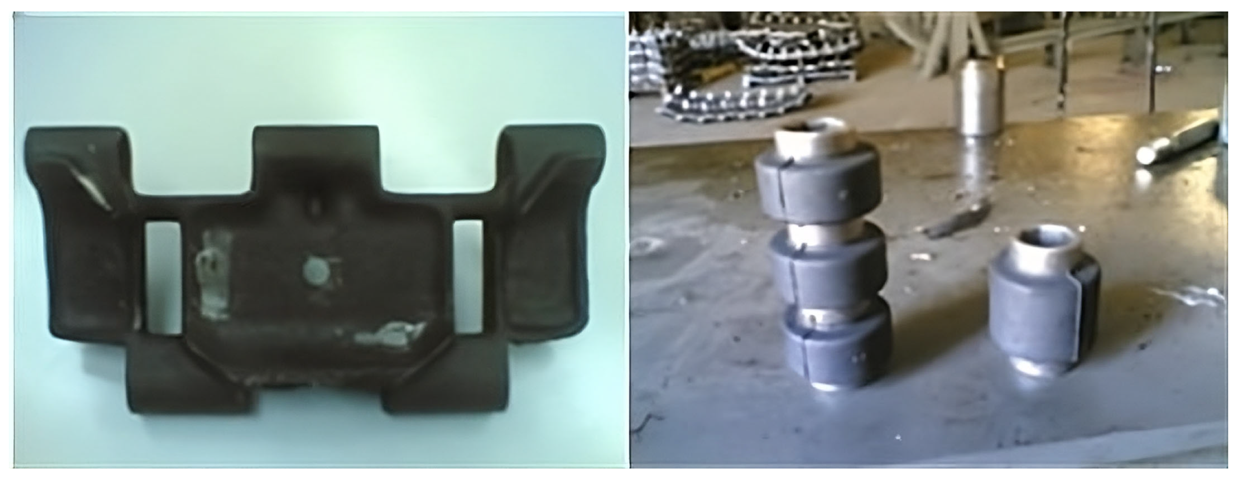
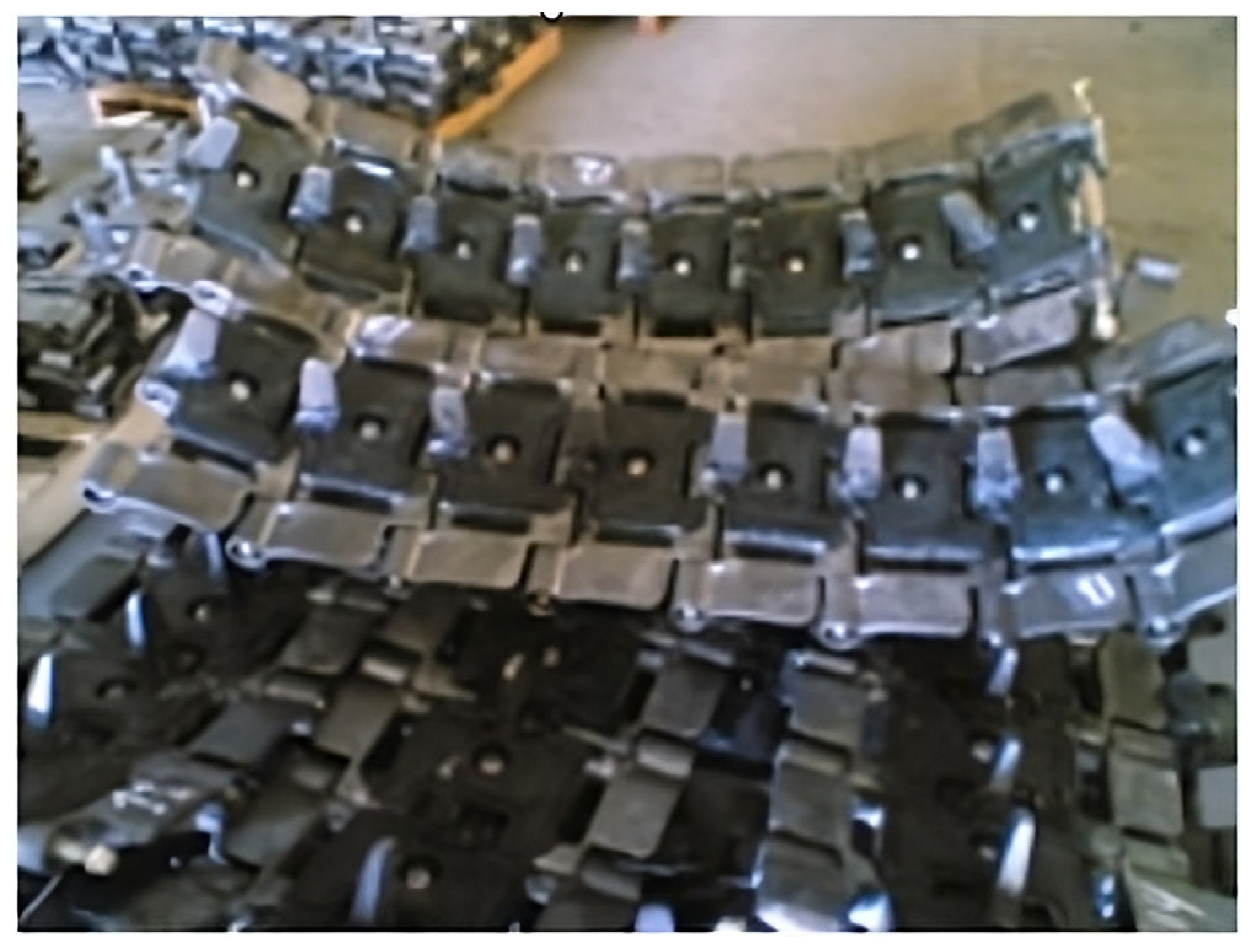
A preliminary study showed that the existing process of track assembly uses a relatively inefficient technology characterized by low productivity, heavy manual effort, and excessive material handling operations. The recognized design problems include:
  • The broaching rod breaks frequently and gets jammed inside the sockets. This leads to discarding both the broaching rod and the damaged link. A broaching rod costs $900. Failure analysis revealed that causes of failure include unacceptable levels of out-of-roundness in link sockets and misalignment of sockets axes. These defects, in turn, are caused by defective mold and inadequate casting process.
  • The hydraulic piston rod in the bushing installation operation loses its standard angular orientation frequently and requires recalibration.
  • Control knobs of the hydraulic press at the bushing assembly workstation require the operator to use both hands. This slows down the operation and causes fatigue to the worker.
  • A high number of rubberized bushings are damaged during the pressing operation. A bushing cost is about $12. This damage occurs when the hydraulic piston just starts to press the bushing into the socket.
  • The bushing assembly operation is of low productivity and forms a bottleneck. The productivity is about 60 links per shift.
  • Excessive material handling within and between the three work stages.
This case study aims to improve the overall efficiency of the assembly workshop through the redesign of the assembly operations.

3.1. Building the Modified HoQ for the Workshop

  • Step 1: Identify the customers
The customers of the assembly process are classified into four groups: (1) Managers (C1): those who take the responsibility to manage the workshop, (2) Workers (C2): those who work in the assembly workstation, (3) Consumers (C3): those who will buy the assembled product, and (4) Repair (C4): those who will disassemble and repair the track links. Importance weights of customer groups are tentatively assigned by researchers on a scale from 1 to 10, and are then normalized as shown in Table 2.
  • Step 2: Determine the Customer Requirements
Informal interviews with the customers were conducted to determine their requirements, as summarized in Table 3. Moreover, the overall procedures and situation in the workshop were observed and evaluated by the researchers.
  • Step 3: Determine the relative importance of the customer requirements
The importance of the customer requirements (min) was expressed based on the scale: 1 (not important), 2 (very low), 4 (low), 6 (moderate), 8 (high) and 10 (very high). The relative importance (MRi) and the importance weight (WRi) of the customer requirements were then calculated as in Table 4.
  • Step 4: Identify and evaluate the competition
Since no similar assembly process was located near to the research region, the currently existing workshop is considered as the competing product or system. The existing workshop was assessed relative to the requirements based on the scale: 1 (very poor), 3 (poor), 5 (neutral), 7 (good) and 10 (excellent). The overall satisfaction degree (SDk) of the existing workshop was calculated, as shown in the last column of Table 4. The overall satisfaction degree of the existing workshop design is estimated at 3.1, which translates to a “low” satisfaction level.
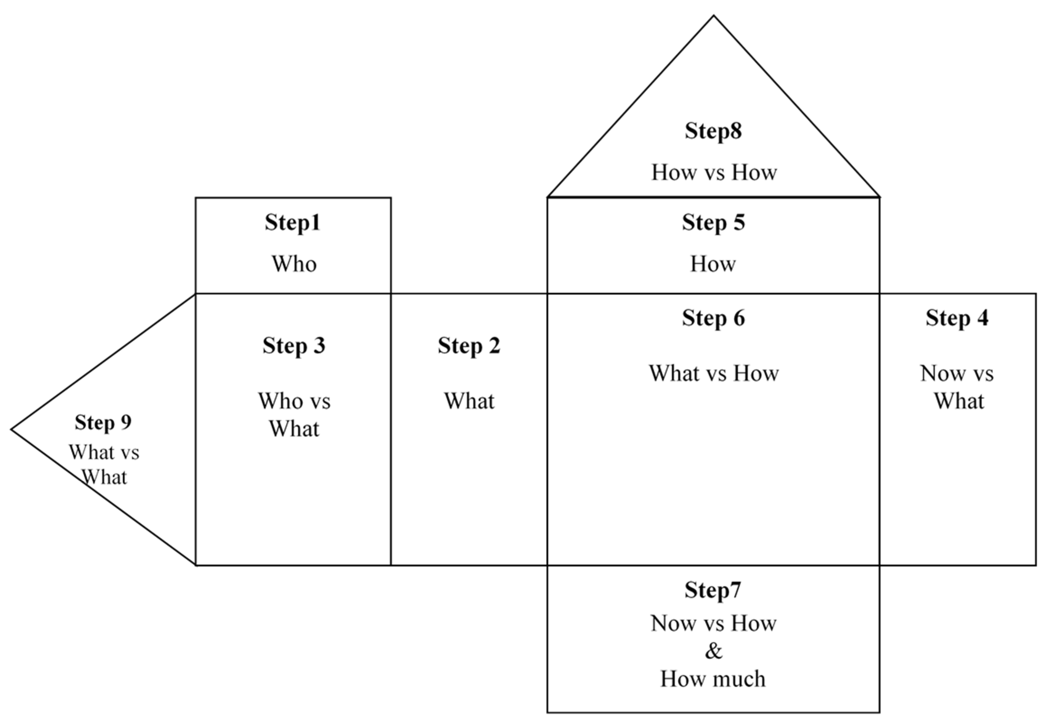
In steps 5 and 6, the designer needs to identify the design specifications based on the knowledge of the process, and then correlate these specifications to the customers’ requirements. Then in steps 7 and 8, the designer needs to set the target values of the specifications that satisfy the customer’s requirements and examine the correlation between the design specifications in order to identify the contradictions.
  • Step 5: Generate design specifications
The design parameters for the workshop were generated by analyzing the workshop processes and customer requirements. The units of measurement and the direction of improvements of the design parameter were also determined as shown in Table 5.
  • Step 6: Relate customer requirements to design parameters
The relationships between design parameters and customer requirements were determined based on the scale: 0 (no relation), 1 (very weak), 3 (weak), 5 (moderate), 7 (strong) and 9 (very strong). The weights of the design parameters were calculated by analyzing to what extend each design parameter could technically be influenced by and correlated with the customer requirements. The resulting relationships between requirements and parameters (xij) and the parameter weight (WPj) are shown in Table 6.
  • Step 7: Set target values for design parameters
The existing workshop machines and the output product were assessed relative to the design parameters, and the target values were set based on these measurements as shown in Table 7.
  • Step 8: Determine the relationships between design parameters
The relationships between the design parameters (CPjj′) were determined based on the scale: −3 (strong negative), −1 (negative), 0 (no relation), 1 (positive) and 3 (strong positive), and are shown at the bottom left half of Table 8. The contradiction index value (CIjj′) for the negative relationships or contradictions were calculated and listed in the upper right half of Table 9. The contradiction threshold value (CCVj) for the design parameters is estimated at 0.78, and cells with absolute contradiction index values greater than 0.78 are highlighted.
  • Step 9: Determine the relationships between customers’ requirements
The relationships between the customer requirements (CRii′) and contradiction index values (CIii′) were determined using the same scale in the previous step, and are shown in Table 9. The contradiction critical value (CCVi) for the customer requirements was estimated at 1.18, and critical contradictions are highlighted.
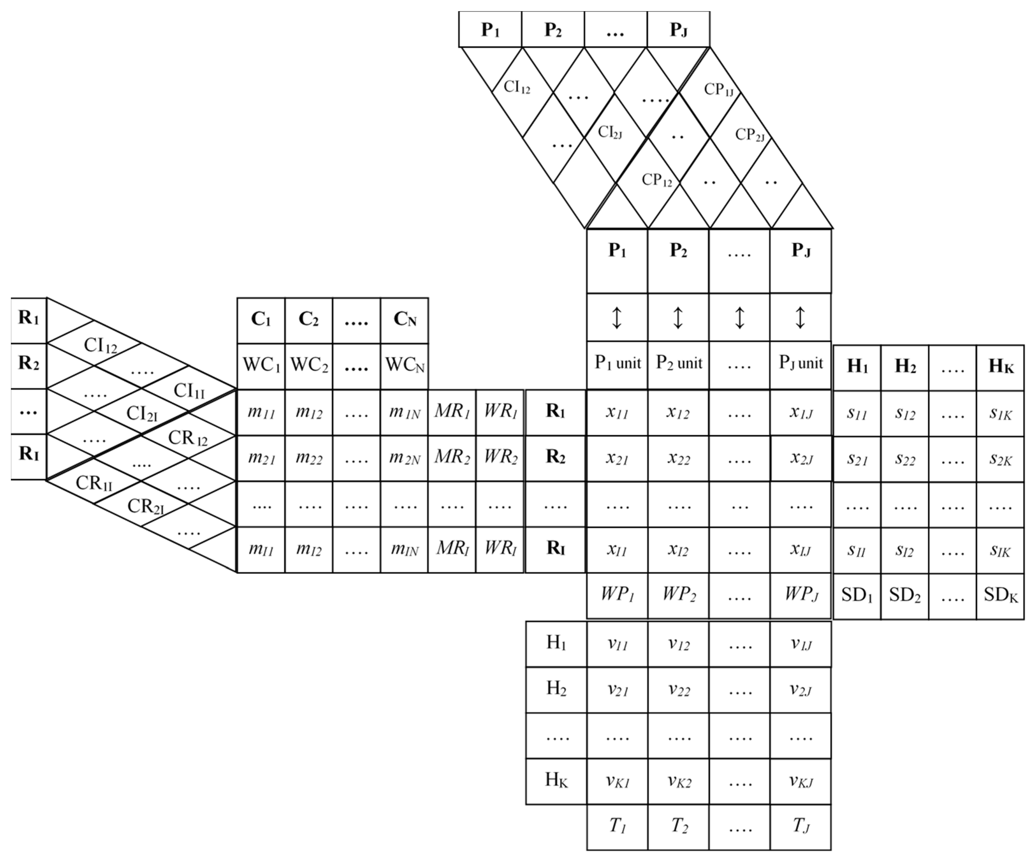
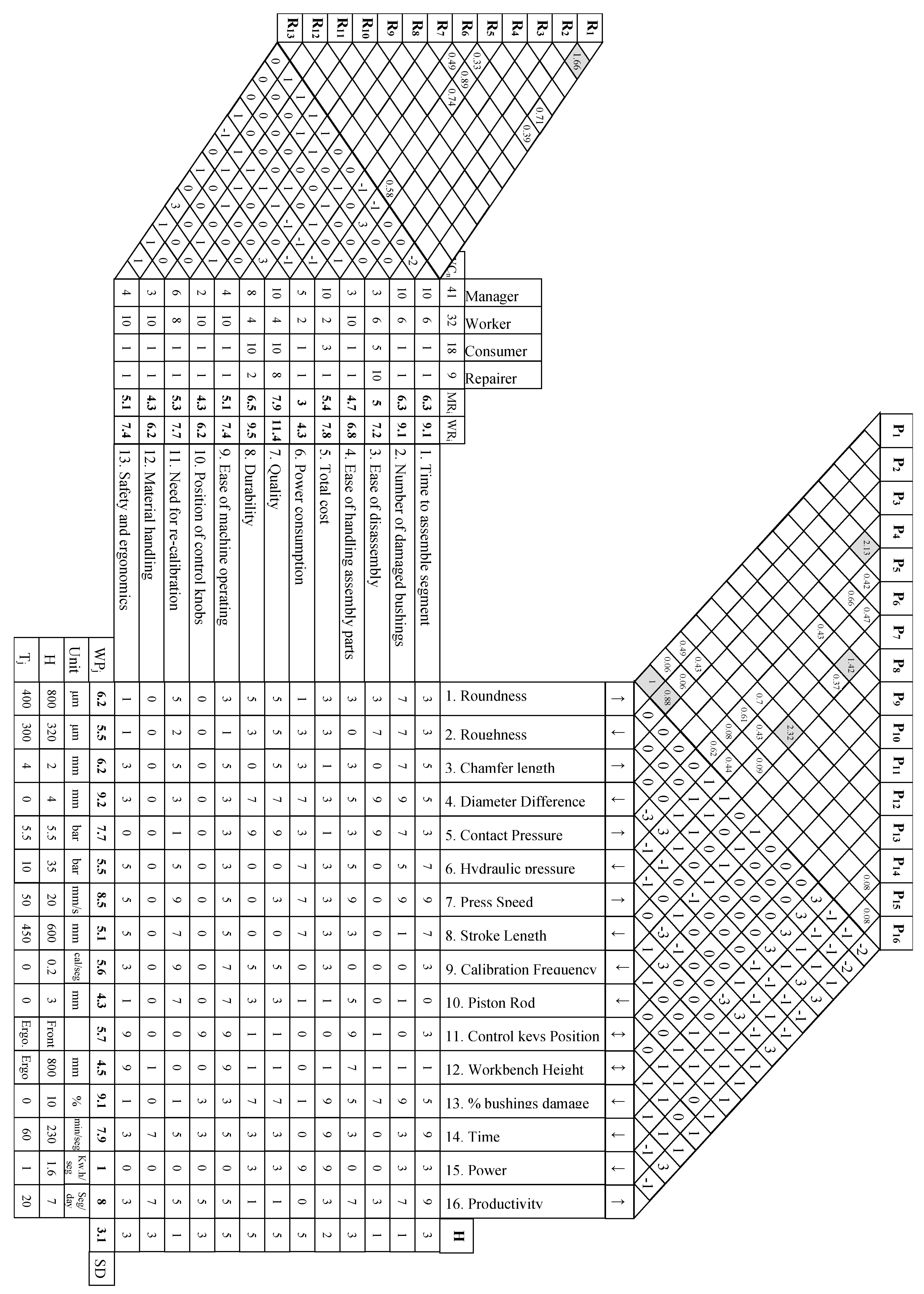
Figure 6 shows the complete modified HoQ for the assembly workshop based on obtained results.

3.2. Solving Contradictions Using TRIZ Inventive Principles

The roof of the modified HoQ shown in Figure 6 contains two rooms: the right room contains the relationships between the design parameters and the left room contains the absolute value of the contradiction indexes of the contradicting parameters. The contradiction indexes of the critical contradictory parameters are highlighted. The critical contradictory parameters are (1) “7. Press Speed” vs. “13. Percent bushings damaged”, (2) “4. Diameter Difference” vs. “5. Contact Pressure”, (3) “7. Press Speed” vs. “9. Calibration Frequency”, (4) “1. Roundness” vs. “16. Productivity”, and (5) 2. “Roughness” vs. “16. Productivity” with contradiction indexes 2.32, 2.13, 1.42, 1.00 and 0.88 respectively.
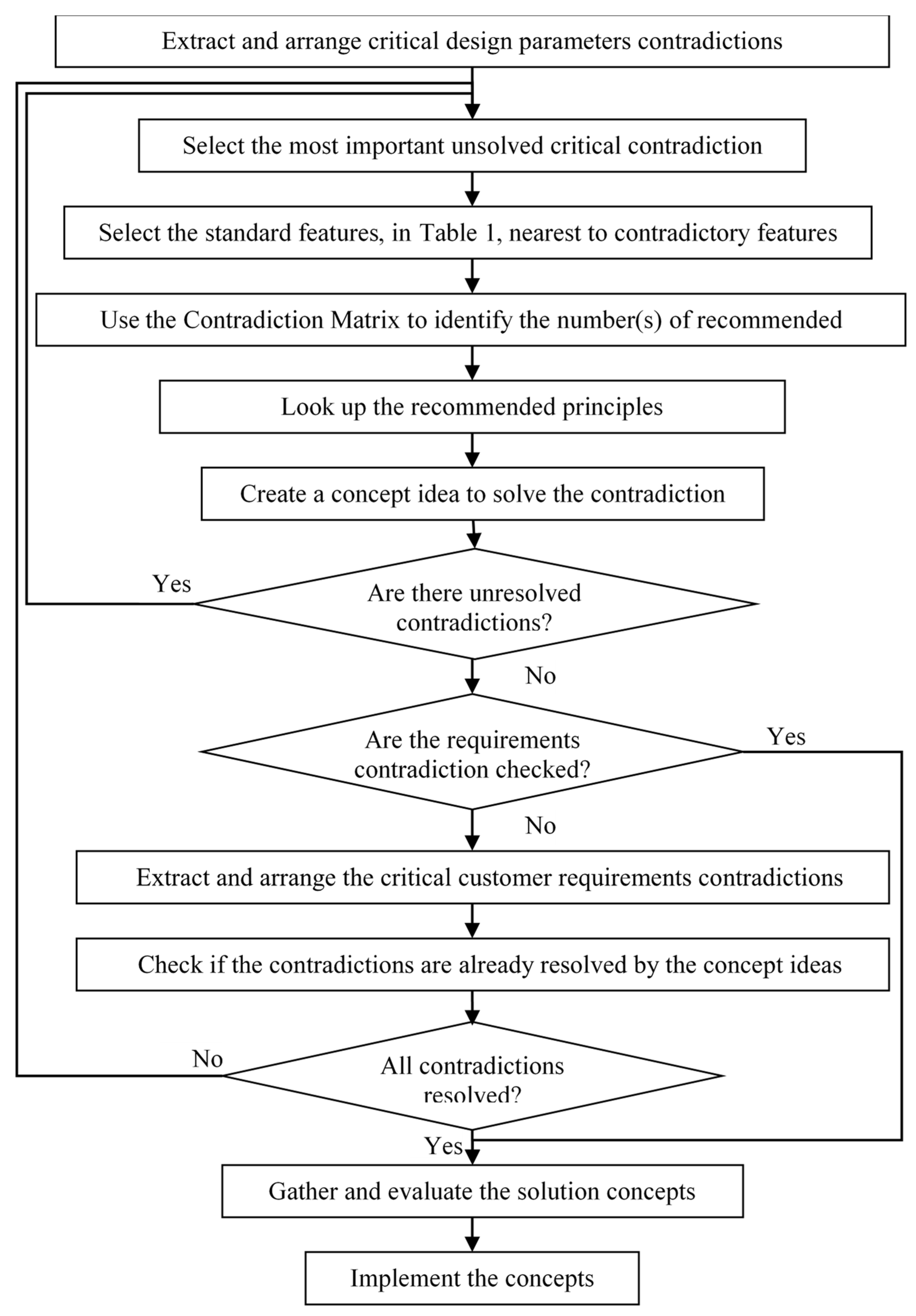
The proposed methodology to solve the contradictions using the Contradiction Matrix is applied to resolve the critical contradictions:
1.
“Press Speed” vs. “Percent Bushings Damaged”
When the press speed is increased, the rubberized bushings get damaged at the beginning of the pressing process. So, the improved parameter is “Press Speed” and the worsened parameter is “Percent Bushings Damaged”. The standard feature closest to the improved parameter is “9. Speed”, and is “31. Object-Generated harmful factors” for the worsened parameter. Therefore, using the Contradiction Matrix, the numbers of the recommended inventive principles are 2: Extraction, 24: Mediator, 35: Parameter Change, and 21: High Speed (Rush Through).
The Mediator principle leads us to think about using an auxiliary part to facilitate the insertion process and avoid damaging the rubber. This mediator can be a steel bar with a truncated conical hole, fixed to the machine with a gradually decreasing inner diameter; the large diameter is greater than the bushing diameter and the small one is less than the socket bore diameter. The inner surface of the cone must be sufficiently smooth to reduce friction during insertion. Alternatively, thinking the Parameter Change principle, the idea can be to heat the rubberized bushings within the elastic range to make the rubber more flexible. This would allow inserting the rubberized bushing with less force and at a higher speed without damage. A study of the change in the elastic properties of the rubberized bushing with temperature is needed to determine the suitable temperature for the process. A combination of the two solution alternatives can also be considered.
2.
“Diameter Difference” vs. “Contact Pressure”
The outside bushing diameter is made larger than the socket diameter so that a press-fit is obtained. The less the dimeter difference, the less the pressing force needed. However, by decreasing the diameter difference, the contact pressure also decreases, which is undesirable because a relatively high contact pressure is needed to keep bushings in place. So, the improved parameter is “Diameter Difference”, and the worsened parameter is “Contact Pressure.” The standard feature closest to the improved parameter is “3. Length of moving object”, and is “11. Pressure” for the worsened parameter.
Looking up the Contradiction Matrix, the numbers of the recommended inventive principles are 1: Segmentation, 8: Counter Force, and 35: Parameter Change. The Segmentation Principle suggests segmenting the bushing so that it can be “folded” prior to insertion and “deployed” after insertion. The Parameter Change principle leads us to the idea of heating up the rubberized bushings, as mentioned in the previous section. Rubberized bushings are softened by heating, which simplifies the insertion process, and the contact pressure is recovered as the rubber cools down and hardens.
3.
“Press Speed” vs. “Calibration Frequency”
When the press speed is increased, the octagonal hydraulic piston rod loses its orientation more quickly and hence needs recalibration more frequently. So, the improved parameter is “Press Speed”, and the worsened parameter is “Calibration Frequency.” The standard feature closest to the improved parameter is “9. Speed” and is “15. Duration of action by moving object” for the worsened parameter. Using the Contradiction Matrix, the numbers of the recommended inventive principles are 3: Local Quality, 19: Periodic Action, 35: Parameter Change, and 5: Merging.
The Local Quality Principle suggests that the press speed be decreased only at the insertion stage. The press speed can be increased at all other motion stages without harm to the operation or the calibration. The Periodic Action Principle would suggest replacing the continuous movement of the piston with a periodic pulse movement. The Merging Principle would bring us to the idea of combining (merging) the bushing insertion operation with the axle installation operation. The proposed idea suggests inserting the 5 bushings into the 5 sockets in one piston stroke. This requires some of the bushings to pass through more that one hole, which increases the probability of bushings damage. If the idea of elevating bushings temperature is also applied, the multiple passing can be done without damaging the bushings. Applying this combined solution eliminates the need for adjusting the orientation of the bushings, and hence eliminates the need for the frequent recalibration of the settings of the piston rod. Moreover, this solution allows transferring the 10-degree orientation setting to the track assembly workbench, making it a built-in rigid setting.
4.
“Roundness” vs. “Productivity”
The broaching process aims to improve the roundness of the socket bore. Increasing the “Roundness” parameter decreases the “Productivity” since a secondary operation (broaching) is required. Hence, the improved parameter is “Roundness”, and the worsened parameter is “Productivity”. The standard feature closest to the improved parameter is “12. Shape”, and is “39. Productivity” for the worsened parameter. Using the Contradiction Matrix, the numbers of the recommended inventive principles are 17: Another Dimension, 26: Use of Copies, 34: Discard and Recover, and 10: Prior Action.
The Prior Action principle leads to thinking about taking measures to improve socket roundness and inner surface finish to eliminate the need for the broaching process. This implies improving control over the casting process and mold design. On the other hand, the solution concepts discussed in the sections above also relieve the problems arising from the out-of-roundness defect. The broaching process can then be eliminated, hence resolving the contradiction.
5.
“Roughness” vs. “Productivity”
Cast track links come with unacceptable inner surface roughness. Increased “Roughness” parameter decreases “Productivity”. So, the improved parameter is “Roughness”, and the worsened parameter is “Productivity”. The standard feature closest to the improved parameter is “12. Shape”, and is “39. Productivity” for the worsened parameter. Using the Contradiction Matrix, the numbers of the recommended inventive principles are 17: Another Dimension, 26: Use of Copies, 34: Discard and Recover, and 10: Prior Action. The inventive principles are like those recommended for “Roundness” vs. “Productivity” above. Therefore, the same solution (Prior Action) resolves this contradiction.
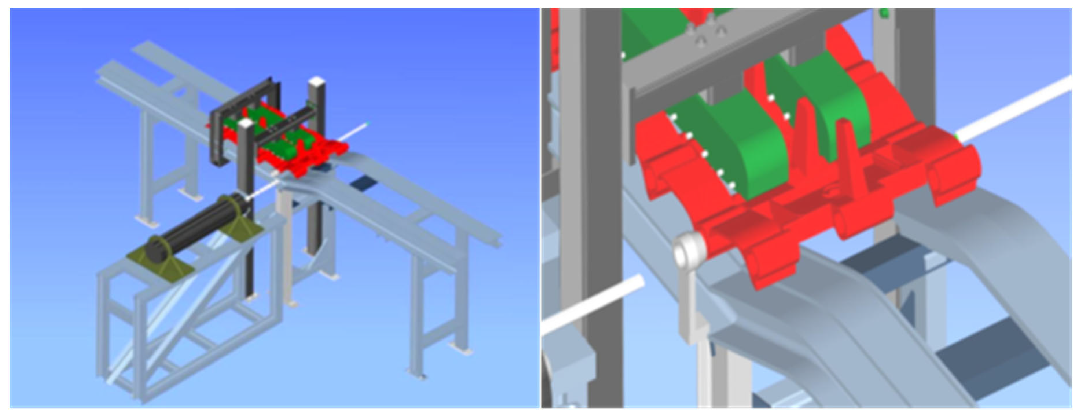
The proposed design combines the solutions generated from resolving of the design parameter contradictions: (1) Using a mediator with a truncated conical hole to facilitate the bushings pressing process, (2) Heating up the rubberized bushings to increase their flexibility to simplify the pressing process and reduce the bushings damage, (3) Combining (merging) the bushing insertion process with the track axle installation process, and (4) Controlling the casting process quality to eliminate the broaching operation. Prior to implementing the final design of the assembly workshop, the values of the free-design parameters (Control keys Position and Workbench Height) that result in ergonomic problems are set. To free the hands of the machine operator and decrease physical effort, the hydraulic press control knob, which is located at knee height in the current design, is redesigned to be placed on the floor and foot actuated. Moreover, the height of the workbench, not ergonomically set in the current design, is readjusted to the ergonomic height range for the operators as recommended in [40].
Following resolving the critical contradiction between the design parameters, the critical contradictions between the customer requirements are re-inspected to find out if they have been resolved. Only one critical contradiction between the customer requirements, “1. Time to Assemble Segment” vs. “2. Number of Damaged Bushings” with a contradiction index of 1.66, is identified. In this contradiction, the customers require reducing the total time to assemble each track segment without damaging the bushings. This contradiction has been resolved by the solutions developed for resolving contradictions between other design parameters.

3.3. The Proposed Design

The new design, shown in Figure 7, suggests producing the track link segments on one machine rather than three machines. The new design of the workstation has the following features: (1) A short steel bar with a truncated conical hole is used in front of piston rod at an adjustable distance, (2) A pair of track links is assembled on one machine workbench. The links are fixed on the machine top surface fixture that allows positioning one link horizontally while the other link is inclined at 10-degrees to horizontal, (3) The machine has a long workbench that accommodates up to eight track links at the same time. The height of the workbench is within the ergonomic range, (4) The hydraulic knob controller is located on the floor under the machine and operated by foot, and (5) A low-temperature furnace is used to heat up the rubberized bushings before the fitting process. The proposed assembly process of a track link segment would proceed as follows: (1) Heat the rubberized bushings to suitable working temperature in the low-temperature furnace, (2) Install two track links in the assembly fixture, (3) Place five rubberized bushings on the piston rod, and then press it sequentially into the assembled links sockets through the steel conical part in one stroke, (4) Insert the link axel through the assembled rubberized bushings, (5) Assemble another track link to the previous two links already assembled, and (6) Repeat the process to complete assembling eight links, the final product.
The proposed design solution incorporates several new features directed at improving the overall process in comparison with the existing one. The new design (1) saves time and improves the productivity of the workshop, (2) decreases the costs through the elimination of some processes and the reduction in bushings damage, (3) improves worker time utilization and decreases the number of workers: 2 workers can collaborate to complete the process activities compared to 4 workers in the current design, (4) eliminates the need to adjust the orientation of the bushings, which is set on the piston rod (which loses its setting over time) in the existing design, (5) decreases the need for multiple re-fixturing (fix-remove-transport-fix) in the current design to fixturing only once, (6) eliminates the need for material handling between machines, and (7) enhances work ergonomics by reducing the physical and mental efforts of operators.

4. Conclusions

The paper develops and implements a methodology to integrate TRIZ and QFD for the innovative redesign of an assembly workstation. The methodology modifies the HoQ to analytically weigh up the various customer requirements and translate them to weighted design parameters, and to reveal and prioritize contradictions between design parameters and between customer requirements. Consequently, the modified HoQ reduces the need for the alternative TRIZ Functional Analysis procedure to identify contradiction. Applying the proposed methodology to redesign an assembly workshop illustrates the ability of the proposed methodology to solve complicated and complex design problems. The proposed method is limited to the use of significant process redesign and is not suitable for simple process improvement. The new assembly workshop design resolved the many major assembly problems addressed by the various stakeholders of the process and improved the overall system efficiency.

Author Contributions

Conceptualization, S.H. and A.A.-D.; methodology, S.H. and A.A.-D.; software, S.H.; validation, O.A.-A. and A.A.-D.; formal analysis, S.H.; investigation, S.H., A.A.-D. and O.A.-A.; resources, A.A.-D. and O.A.-A.; data curation, S.H., A.A.-D. and O.A.-A.; writing—original draft preparation, S.H. and A.A.-D.; writing—review and editing, O.A.-A.; visualization, S.H., A.A.-D. and O.A.-A.; supervision, A.A.-D.; project administration, A.A.-D.; funding acquisition, no funding. All authors have read and agreed to the published version of the manuscript.

Funding

This research received no external funding.

Conflicts of Interest

The authors declare no conflict of interest.

References

  1. Dorst, K.; Cross, N. Creativity in the design process: Co-evolution of problem–solution. Des. Stud. 2001, 22, 425–437. [Google Scholar] [CrossRef]
  2. Dieter, G.E.; Schmidt, L.C. Engineering Design, 5th ed.; McGraw-Hill: New York, NY, USA, 2013. [Google Scholar]
  3. Ulrich, K.A.; Eppinger, S.T. Product Design and Development, 6th ed.; McGraw-Hill: New York, NY, USA, 2016. [Google Scholar]
  4. Ullman, D.A. The Mechanical Design Process, 5th ed.; McGraw-Hill: New York, NY, USA, 2015. [Google Scholar]
  5. Rantanen, K.A.; Domb, E.L. Simplified TRIZ New-Problem Solving Applications for Engineering and Manufacturing Professionals; ST. Lucie Press: Landon, FL, USA, 2000. [Google Scholar]
  6. Akao, Y.O. Quality Function Deployment: Integrating Customer Requirements into Product Design; Productivity Press: New York, NY, USA, 1990. [Google Scholar]
  7. Griffin, A.; Hauser, J.R. The Voice of Customer. Mark. Sci. 1993, 12, 1–27. [Google Scholar] [CrossRef]
  8. Min, D.A.; Kim, K.W. An Extended QFD Planning Model for Selecting Design Requirements with Longitudinal Effect Consideration. Expert Syst. Appl. 2007, 8, 1546–1554. [Google Scholar] [CrossRef]
  9. Kwong, C.K.; Chen, Y.; Bai, H.; Chan, D.S. A Methodology of Determining Aggregated Importance of Engineering Characteristics in QFD. Comput. Ind. Eng. 2007, 53, 667–679. [Google Scholar] [CrossRef]
  10. Chen, L.I.; Weng, M.I. A Fuzzy Model for Exploiting Quality Function Deployment. Math. Comput. Model. 2003, 38, 559–570. [Google Scholar] [CrossRef]
  11. Hana, C.H.; Kimb, J.A.; Choi, S.A. Prioritizing Engineering Characteristics in Quality Function Deployment with Incomplete Information: A Linear Partial Ordering Approach. Int. J. Prod. Econ. 2004, 91, 235–249. [Google Scholar] [CrossRef]
  12. Lai, X.I.; Xie, M.I.; Tan, K.A.; Yang, B.O. Ranking of Customer Requirements in a Competitive Environment. Comput. Ind. Eng. 2008, 54, 202–214. [Google Scholar] [CrossRef]
  13. Delice, E.L.; Gungor, Z.U. A New Mixed Integer Linear Programming Model for Product Development Using Quality Function Deployment. Comput. Ind. Eng. 2009, 27, 906–912. [Google Scholar] [CrossRef]
  14. Zheng, L.I.; Chin, K.W. QFD based optimal process quality planning. Int. J. Adv. Manuf. Technol. 2005, 26, 831–841. [Google Scholar] [CrossRef]
  15. Orloff, M.I. Inventive Thinking through TRIZ, 2nd ed.; Springer: Berlin/Heidelberg, Germany, 2006. [Google Scholar]
  16. Altshuller, G.S. Creativity as an Exact Science; Gordon and Breach: New York, NY, USA, 1984; p. 228. [Google Scholar]
  17. Altshuller, G.S.; Shulyak, L.E. 40 Principles: TRIZ Keys to Technical Innovation; Technical Innovation Center: Worcester, MA, USA, 1998. [Google Scholar]
  18. Mann, D. Evolving the Inventive Principles. TRIZ J. 2002. [Google Scholar]
  19. Tong, L.H.; Cong, H.E.; Lixiang, S.H. Automatic classification of Patent Documents for TRIZ Users. Word Pat. Inf. 2006, 28, 6–13. [Google Scholar]
  20. Chang, H.T.; Chen, J.L. The Conflict-Problem-Solving CAD Software Integrating TRIZ into Eco-Innovation. Adv. Eng. Softw. 2004, 35, 553–556. [Google Scholar] [CrossRef]
  21. Kim, J.U.; Kim, J.I.; Lee, Y.O.; Lim, W.O.; Moon, I.I. Application of TRIZ Creativity Intensification Approach to Chemical Process Safety. J. Loss Prev. Process Ind. 2009, 6, 1039–1043. [Google Scholar] [CrossRef]
  22. Robles, G.C.; Negny, S.T.; Lann, J.M. Case-Based Reasoning and TRIZ: A coupling for Innovative Conception in Chemical Engineering. Chem. Eng. Process 2009, 48, 239–249. [Google Scholar] [CrossRef]
  23. Robles, G.C.; Negny, S.T.; Lann, J.M. Design Acceleration in Chemical Engineering. Chem. Eng. Process 2008, 47, 2019–2028. [Google Scholar] [CrossRef]
  24. Russo, D.; Spreafico, C. Investigating the multilevel logic in design solutions: A Function Behaviour Structure (FBS) analysis. Int. J. Interact. Des. Manuf. 2023, 17, 1789–1805. [Google Scholar] [CrossRef]
  25. Li, F.; Chen, C.; Lee, C.; Khoo, L. A User Requirement-driven Approach Incorporating TRIZ and QFD for Designing a Smart Vessel Alarm System to Reduce Alarm Fatigue. J. Navig. 2020, 73, 212–232. [Google Scholar] [CrossRef]
  26. Frizziero, L.; Francia, D.; Donnici, G.; Liverani, A.; Caligiana, G. Sustainable design of open molds with QFD and TRIZ combination. J. Ind. Prod. Eng. 2018, 35, 21–31. [Google Scholar] [CrossRef]
  27. Caligiana, G.; Liverani, A.; Francia, D.; Frizziero, L.; Donnici, G. Integrating QFD and TRIZ for innovative design. J. Adv. Mech. Des. Syst. Manuf. 2017, 11, JAMDSM0015. [Google Scholar] [CrossRef]
  28. Naveiro, R.; Oliveira, V. QFD and TRIZ integration in product development: A Model for Systematic Optimization of Engineering Requirements. Production 2018, 28, e20170093. [Google Scholar] [CrossRef]
  29. Donnici, G.; Frizziero, L.; Liverani, A.; Leon-Cardenas, C. Design for Six Sigma and TRIZ for Inventive Design Applied to Recycle Cigarette Butts. Design 2022, 6, 122. [Google Scholar] [CrossRef]
  30. Lyu, J.; Chen, R.; Yang, L.; Wang, J.; Chen, M. Applying a Hybrid Kano/Quality Function Deployment Integration Approach to Wood Desk Designs for Open-Plan Offices. Forests 2022, 13, 1825. [Google Scholar] [CrossRef]
  31. Carneiro, T.; Oliveira, J.; Baptista, A.; Castro, P. Enhancement of the LeanDfX Product Development Framework and Application to the Design of an AGV Structure. Designs 2022, 6, 114. [Google Scholar] [CrossRef]
  32. Wang, C. Incorporating the concept of systematic innovation into quality function deployment for developing multi-functional smart phones. Comput. Ind. Eng. 2017, 107, 367–375. [Google Scholar] [CrossRef]
  33. Francia, D.; Caligiana, G.; Liverani, A.; Frizziero, L.; Donnici, G. PrinterCAD: A QFD and TRIZ integrated design solution for large size open moulding manufacturing. Int. J. Interact. Des. Manuf. 2018, 12, 81–94. [Google Scholar] [CrossRef]
  34. Wang, Y.; Lee, C.; Trappey, A. Service design blueprint approach incorporating TRIZ and service QFD for a meal ordering system: A case study. Comput. Ind. Eng. 2017, 107, 388–400. [Google Scholar] [CrossRef]
  35. Vinodh, S.; Kamala, V.; Jayakrishna, K. Integration of ECQFD, TRIZ, and AHP for innovative and sustainable product development. Appl. Math. Model. 2014, 38, 2758–2770. [Google Scholar] [CrossRef]
  36. Zhang, F.; Yang, M.; Liu, W. Using integrated quality function deployment and theory of innovation problem solving approach for ergonomic product design. Comput. Ind. Eng. 2014, 76, 60–74. [Google Scholar] [CrossRef]
  37. Kim, S.; Yoon, B. Developing a process of concept generation for new product-service systems: A QFD and TRIZ-based approach. Serv. Bus. 2012, 6, 323–348. [Google Scholar] [CrossRef]
  38. Wang, H.; Chen, G.; Lin, Z.; Wang, H. Algorithm of integrating QFD and TRIZ for the innovative design process. Int. J. Comput. Appl. Technol. 2005, 23, 41–52. [Google Scholar] [CrossRef]
  39. Yamashina, H.; Ito, T.; Kawada, H. Innovative product development process by integrating QFD and TRIZ. Int. J. Prod. Res. 2002, 40, 1031–1050. [Google Scholar] [CrossRef]
  40. Kroemer, K.H.E. Fitting the Human: Introduction to Ergonomics/Human Factors Engineering, 7th ed.; CRC Press: Boca Raton, FL, USA, 2017. [Google Scholar]
Figure 1. Modified House of Quality.
Designs 07 00132 g001
Figure 2. The modified HoQ with all notations.
Designs 07 00132 g002
Figure 3. Resolving contradictions using TRIZ.
Designs 07 00132 g003
Figure 4. Track link (left) and rubberized bushings (right).
Designs 07 00132 g004
Figure 5. Assembled track segments.
Designs 07 00132 g005
Figure 6. Complete modified HoQ for the assembly workshop.
Designs 07 00132 g006
Figure 7. The proposed design of the assembly workstation.
Designs 07 00132 g007
Table 1. TRIZ principles of innovation and standard features [18].
Principles of InnovationStandard Features
1. Segmentation21. Rush through1. Weight of moving object21. Power
2. Extraction22. Convert harm into benefit2. Weight of stationary object22. Loss of Energy
3. Local quality23. Feedback3. Length of moving object23. Loss of substance
4. Asymmetry24. Mediator4. Length of stationary object24. Loss of Information
5. Consolidation25. Self-service5. Area of moving object25. Loss of Time
6. Universality26. Copying6. Area of stationary object26. Quantity of substance
7. Nesting principle27. Cheap and short lived7. Volume of moving object27. Reliability
8. Counterweight28. Replacement of a mechanical system8. Volume of stationary object28. Measurement accuracy
9. Prior counter-action29. Pneumatic or hydraulic construction9. Speed29. Manufacturing precision
10. Prior action30. Flexible film or thin membranes10. Force (Intensity)30. Object-affected harmful factors
11. Be prepared31. Porous material11. Stress or pressure31. Object-generated harmful factors
12. Equipotentiality32. Changing color12. Shape32. Ease of manufacture
13. Reverse33. Homogeneity13. Stability of the object’s composition33. Ease of operation
14. Spheroidality34. Rejecting and regenerating parts14. Strength34. Ease of repair
15. Dynamicity35. Parameter change15. Duration of action of moving object35. Adaptability or versatility
16. Partial or excessive action36. Phase transition16. Duration of action by stationary object36. Device complexity
17. Move to a new dimension37. Application of heat expansion17. Temperature37. Difficulty of detecting and measuring
18. Mechanical vibration38. Using strong oxidizers18. Illumination intensity38. Extent of automation
19. Periodic action39. Inert environment19. Use of energy by moving object39. Productivity
20. Continuity of useful action40. Composite materials20. Use of energy by stationary object
Table 2. Importance weights for the workshop customers.
CnCustomersAssumed ImportanceImportance Weight (WCn)
C1Managers941%
C2Workers732%
C3Consumers418%
C4Repair29%
Table 3. The customer requirements of the assembly workshop.
RiCustomers RequirementsDescription
R1Time to assemble segmentDecrease the time requires to assemble each of eight track links to an individual segment.
R2Number of damaged bushingsDecrease the number of rubberized bushings that are damaged during the assembly and disassembly processes.
R3Ease of disassemblySimplicity to disassemble the track links segment.
R4Ease of handling of assembly partsSimplicity to control the parts that are used in the assembly process.
R5Total cost of assembly per segmentDecrease total cost to assemble one track segment.
R6Power consumptionDecrease the power consumption that requires assembling each of segments.
R7QualityIncrease the quality of assembled product.
R8DurabilityIncrease the durability of assembled product.
R9Ease of machine operating Simplicity to operate and control the assembly machines.
R10Position of control knobsAppropriate design and position of the machine controller keys.
R11Need for re-calibrationDecrease the need to calibrate the orientations of hydraulic piston arm.
R12Material handling Decrease the material handling between machines
R13Safety and ergonomicsDesign ergonomic machines that operate safely.
Table 4. The relative importance of the customer requirements.
ManagerWorkerConsumerRepairMRiWRi (%)Existing System Assessment
RiWCn41%32%18%9%
R1106116.299.13
R2106116.299.11
R3365104.957.21
R4310114.706.83
R5102315.377.82
R652112.964.35
R71041087.9011.45
R8841026.549.55
R9410115.117.45
R10210114.296.23
R1168115.297.71
R12210114.296.23
R13410115.117.43
The Overall satisfaction Degree (SDk)3.1
Table 5. The design parameters of the assembly workshop.
PjParameterUnitDescription
P1Roundness ↑μmRoundness of bores of track link sockets.
P2Roughness ↓μmRoughness of bores surface of track link.
P3Chamfer length ↑mmChamfer length of track link sockets.
P4Diameter Difference ↓mmDiameter difference between the track link bore diameter and the rubberized bushing outside diameter.
P5Contact Pressure ↑BarSurface contact pressure between bore surface of track link and the rubberized bushings.
P6Hydraulic pressure ↓barThe pressure of the hydraulic piston that presses the rubberized bushings.
P7Press Speed ↑mm/sThe speed of hydraulic press that pressed the rubberized bushing into link sockets.
P8Stroke Length ↓mmThe stroke length of the hydraulic press piston rod.
P9Calibration Frequency ↓Calibration/segmentThe number of machines calibration per track segment.
P10Piston Rod Deflection ↓mmThe bending deflection of the hydraulic press piston rod.
P11Control keys Position ↕ The position of hydraulic control keys on the machine.
P12Workbench Height ↕mmThe height of the workbench.
P13% bushings damaged ↓%The percent of damaged bushings during the assembly process.
P14Time ↓min/segmentThe required time to assemble one segment.
P15Power ↓Kw·h/segmentThe power required to assemble one segment.
P16Productivity ↑Segment/dayThe number of segments assembled per shift.
Point up arrow: The higher the better. Point down arrow: Lower is better.
Table 6. The relationship between the customer requirements and the design parameters of the assembly workshop.
P1P2P3P4P5P6P7P8P9P10P11P12P13P14P15P16
RiWPj6.25.56.29.27.75.58.55.15.64.35.74.59.17.91.08.0
R13355379730315939
R27779759101019337
R33709900000117003
R43035359305975307
R53313133331019993
R61337377701001090
R75557903053117331
R85307900053117331
R93153335577993505
R100000000000903305
R115253159797001505
R120000000000010707
R131133055531991303
Point up arrow: The higher the better. Point down arrow: Lower is better.
Table 7. Target values of the design parameters.
PjMeasurement (vkj)Target Value (Tj)
P1800 μm400 μm
P2320 μm300 μm
P32 mm4 mm
P44 mm0 mm
P55.5 bar5.5 bar
P635 bar10 bar
P720 mm/s50 mm/s
P8600 mm450 mm
P90.2 calib/segment0 calib/segment
P103 mm0 mm
P11Front workbenchErgonomic position
P12800 mmErgonomic height
P1310%0%
P14230 min60 min
P151.6 KW·h1 KW·h
P167 segment/day20 segment/day
Table 8. Relationships between design parameters for the assembly workshop.
P1P2P3P4P5P6P7P8P9P10P11P12P13P14P15P16
P1 0.490.061.00
P20 0.430.060.88
P300
P4000 2.13
P5000−3 0.420.66 0.43 0.700.610.080.62
P61113−1 0.47 0.43 0.44
P71111−1−1 1.420.37 2.32 0.09
P80000000
P91111−11−31
P10000000−131
P110000000000
P1200000000000
P133333−11−301111
P14−1−111−1−13111111 0.08
P15−1−113−11−1111001−1 0.08
P16−2−213−1−131111113−1
Dark grey: no relation between the same parameter; Light grey: means this is a critical contradiction.
Table 9. The customer requirements relationships for the assembly workshop.
R1R2R3R4R5R6R7R8R9R10R11R12R13
R1 1.66 0.710.39
R2−2
R300
R4000
R5−1301 0.330.890.74 0.58
R6−1000−1 0.49
R70111−1−1
R80000−103
R911011000
R10110010001
R111000111010
R1210001100000
R130001−10003111
Dark grey: no relation between the same parameter; Light grey: means this is a critical contradiction.
Disclaimer/Publisher’s Note: The statements, opinions and data contained in all publications are solely those of the individual author(s) and contributor(s) and not of MDPI and/or the editor(s). MDPI and/or the editor(s) disclaim responsibility for any injury to people or property resulting from any ideas, methods, instructions or products referred to in the content.

