1. Introduction
Microgrids have been recently prioritised in the agenda of the world of power utilities. A number of challenges related to microgrid operation have been reported, and several solutions have been suggested in the literature. One of the common technical issues is related to the power sharing between dispatchable distributed generation units (DDGUs) within the microgrid [
1]. If a microgrid has only one large DDGU along with other small non-dispatchable distributed generation units (NDDGUs) (mainly renewable energy sources without energy storage) then only the a single DDGU will have to compensate for any variations in the demand or generation from NDDGUs. However, if the microgrid has multiple DDGUs, they all must act in a coordinated manner in response to the changes in the demand, generation, and network configuration.
Advances in power electronics and inverter-based renewable generation (IBRG) along with flexible AC transmission-system technologies facilitated the conversion of NDDGUs to partially dispatchable sources through the addition of battery energy storage systems (BESS). Furthermore, innovations in power electronics-based generation have also resulted in developing gird forming inverters with advanced grid supporting features such as virtual synchronous machine (VSM) control, fast frequency response and dynamic voltage control [
2,
3,
4]. These advancements have proven that a micro-grid can operate solely based on renewable energy sources [
5].
With respect to the interconnection to the main grid, micro grids can be classified broadly into two categories, namely isolated and interconnected microgrids. Isolated microgrids, as name implies, operate without any interconnection with the main grid while interconnected microgrid may have single or multiple interconnection(s) to a single or multiple larger power systems as compared to the size of the microgrid. An interconnected microgrid can be in three possible modes of operation: interconnected to the main gird(s), isolated, and transition [
6,
7]. The disconnection of a microgrid can be either a planned operation or a result of an unplanned outage event. In any case, the interconnected microgrid should be able to remain stable under any mode of operation at any given time.
Ideally, interconnected micro grids should act as a constant load or a constant voltage source with respect to the main grid. This ideal operating scenario is only possible if DDGUs within the micro grid are capable of becoming fully adaptable for the variations in local demand and generation. Variation in local generation can be caused either due to the intermittency of the renewable NDDGUs and/or due to the full or partial outage of any generation source [
8]. Achieving ideal operation of micro grids with a higher renewable penetration level and with varying loads/demand will be more challenging than one with lower renewable penetration and non-varying type load characteristics.
Several solutions have been proposed in the literature for adequate active power sharing within the DDGUs of a micro grid. Power versus frequency (P—f) droop control has been widely adopted in various ways in order to achieve proper power sharing among DDGUs [
9].
Conventionally, frequency-based droop controllers prove to be a very robust, simple and reliable mechanism to manage a generating unit’s response to the varying load or generation in a system. Several studies used (P—f) droop control to ensure that the system’s varying demand is met dynamically by the units [
10]. Since the same frequency signal is fed to all units, a generating unit can easily react to any variations without the need of any additional signal. The value of the droop constant is fixed and pre-determined for each unit. However, there are some other techniques that recommend periodic variation to the droop setting based on the operating conditions of the unit and overall system [
11,
12,
13]. Such methods can be classified as adjustable droop, while the conventional ones can be referred as fixed or constant droop methods.
In [
12,
13], a droop controller is applied to the local DDGUs which continuously changes the droop settings according to the DDGUs current reserve, instead of their capacity. Another method is proposed in [
11], focused on the economic dispatch of the units by dividing the micro grid into smaller areas. A mechanism of centralised control for power sharing using a low bandwidth web-based communication system was proposed in [
14].
In [
15,
16], two different approaches are presented by utilising two modes of DDGU operation, namely unit power control (UPC) mode and feeder flow control (FFC) mode, which were previously proposed in [
10,
17]. A problem was identified in [
15] when multiple DDGs were connected on the same radial feeder and operated in FFC mode.
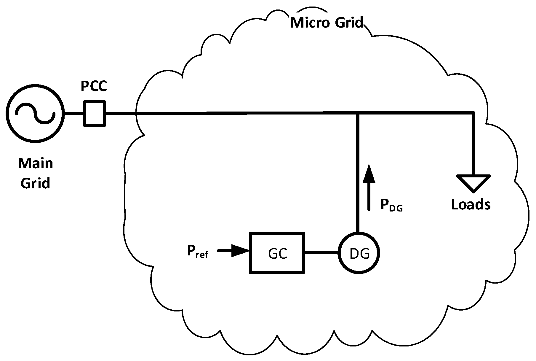
Another method to address the issue of real power sharing among the DDGs of a micro grid is presented in [
16]. It suggests that, ideally, a micro grid will have the largest DDGU connected close to the point of common coupling (PCC) or grid interconnection. The given DDGU will initially operate in FFC mode while the rest of the DDGUs operate in UPC mode. Once, due to the load increase, the FFC unit is fully loaded, the next unit shall switch to FFC mode. This process continues and DDGUs will be switched to the FFC mode once the previous DDGU in the queue reaches its maximum real power output.
Since the main objective of all the power sharing methods is to make the micro grid a constant power consuming or supplying entity, one or more DDGUs need to be operated in FFC mode. To ensure enough reserve in the DDGUs (in FFC mode), for compensating any load/generation variation within the micro grid, the flow from the grid must be kept as high as possible. However, on the other hand, if the flow from (or to) the grid is high, then at the time of isolation (during transition mode) a larger frequency deviation will occur [
16]. A critical balance needs to be maintained so that an unplanned isolation event can be sustained by the micro grid.
Some proposed methods [
11,
14,
18] assumed using one DDGU at the start of each internal feeder, within a micro grid, to keep a constant flow of power on that feeder by operating it in FFC mode. Keeping a constant flow on each internal feeder in turn ensures the overall flow towards or from the micro grid is constant. However, the assumption of having one DDGU at the start of every internal feeder of the microgrid is very idealistic as well as restrictive. Having so many DDGUs within a micro grid can be considered as an expensive luxury and restrictive, because the DDGU will be set to only compensate for variations within the feeder even while having the capacity to contribute to variations in other feeders within the micro grid.
Methods based on the central master controller require communication between the generating units to control or determine the load sharing among the DDGUs and call for additional reliability requirements for the communication and control infrastructure/framework.
Traditionally, operators of DDGUs do not prefer adjustable droop controllers for their units, as this can cause units not to only change their power output level periodically but also at a varying rate. This can cause increased wear and tear to the mechanical components such as valves and pumps.
Constant droop-based methods proved to be more suitable and robust for micro grid applications. However, if the value of the droop constant remains dependent on the network configuration (series/radial or parallel) and/or the number of machines in the system, at any given time, then the method can be classified somewhere in between adjustable and constant droop systems. In such systems, in case if central controller is unavailable for some time, it will require operators to manually calculate new droop constants for each machine [
19,
20].
A two-layered control scheme is proposed in [
21]. The research presented two proposed adaptive and intelligent control schemes for adjusting the micro grid voltage and frequency in islanded mode and facilitating seamless transition between islanded and grid-connected modes. The two proposed controllers were based on improving the performance of the droop-control method based on the H-infinity and model predictive control (MPC) methods. The proposed H-infinity-based control scheme was applied to adjust the micro grid in its islanded mode and to ensure the seamless transition between the two operating modes of the micro grid. In [
22], an enhancement to the droop control, for a more precise control of frequency and voltage profiles of micro grids, was proposed based on harmony search-based H-infinity control. The suggested control method showed better power-quality performance within an isolated micro grid. For modern inverters with advanced features, such as virtual inertia, or inverters that can operate in a mode referred to as a virtual synchronous machine mode, a control method was suggested in [
23]. The proposed method varied the inertia constant and damping coefficient of the swing equation based on a fuzzy control. This method was demonstrated to provide a better frequency response for large load variations within an islanded micro grid. For more precise frequency and voltage regulation and optimization within an isolated micro grid, a further enhanced and hierarchical method, comprising three levels of control, is suggested in [
24]. For a better frequency and voltage response during fault events within a micro grid without any interconnection to the main power system (i.e., isolated), a distributed consensus-based voltage and frequency controller is proposed in [
25].
The above-mentioned power-sharing control methods are mainly proposed for micro grids with one active grid interconnection or for isolated mode of operation of a micro grid. These techniques can be implemented through supervisory control and data acquisition (SCADA), a reliable monitoring system and efficient energy management systems [
26,
27,
28]. It is expected that non-conventional instrument transformers and new communication protocols such as IEC6850 will play a vital role in implementing such techniques on real field applications [
29,
30].
From the above discussion, it can be observed that little attention was given to the development of appropriate power-sharing methods for microgrids with multiple active grid interconnections. As such, the main contribution of this paper can be summarized as follows:
Developing a new general and decentralised active power sharing method that can be employed by microgrids with single or multiple active grid interconnections;
Maintaining the overall active power flow (from all interconnections) into a micro grid at a certain desired level to avoid frequency fluctuation during transition mode;
Controlling the contribution from each DDGU individually;
Facilitating the flexibility of having active power flow at various levels at the interconnections while keeping the overall flow of active power at a certain level.
The paper is organised as follows:
Section 2 provides a detailed description about the modes of operation, UPC and FFC.
Section 3 presents the proposed method, which is Interconnection Flow Control (IFC), while
Section 4 outlines the methodology of its implementation.
Section 5 explains the modelling technique, simulation cases, studied scenarios and presents a detailed commentary about the simulation results. Finally, a conclusion is drawn in
Section 6.
3. Power Sharing in a Micro Grid with Multiple Active Grid Interconnections
A micro grid that can import/export power over multiple active grid interconnections will be more reliable as compared to microgrids with just one active grid interconnection. Multiple grid interconnections, on one hand, provide more flexibility and reliability in operations while, on the other hand, they can introduce some complexity in automatic active power sharing mechanisms. Micro grids can have multiple interconnections with one grid system or can have a single interconnection with multiple grid systems. Grid interconnections can be at different connection points or even at different voltage levels.
To achieve the overall objective of operating a micro grid as either a constant source or load, power flow might have to be kept constant for all of the interconnections. Alternatively, a more likely scenario is to keep the sum of active power flows over interconnections at a constant value, regardless of the individual flows on each interconnection. This paper presents the governor-controller design and mechanism of active power sharing when the sum of the active power flows over the interconnection lines needs to be kept at a constant value, unless all DDGUs run out of headroom capacity.
It is recommended that DDGUs are all operated in interconnection (s) flow control (IFC) mode.
Interconnection Flow Control (IFC) Mode
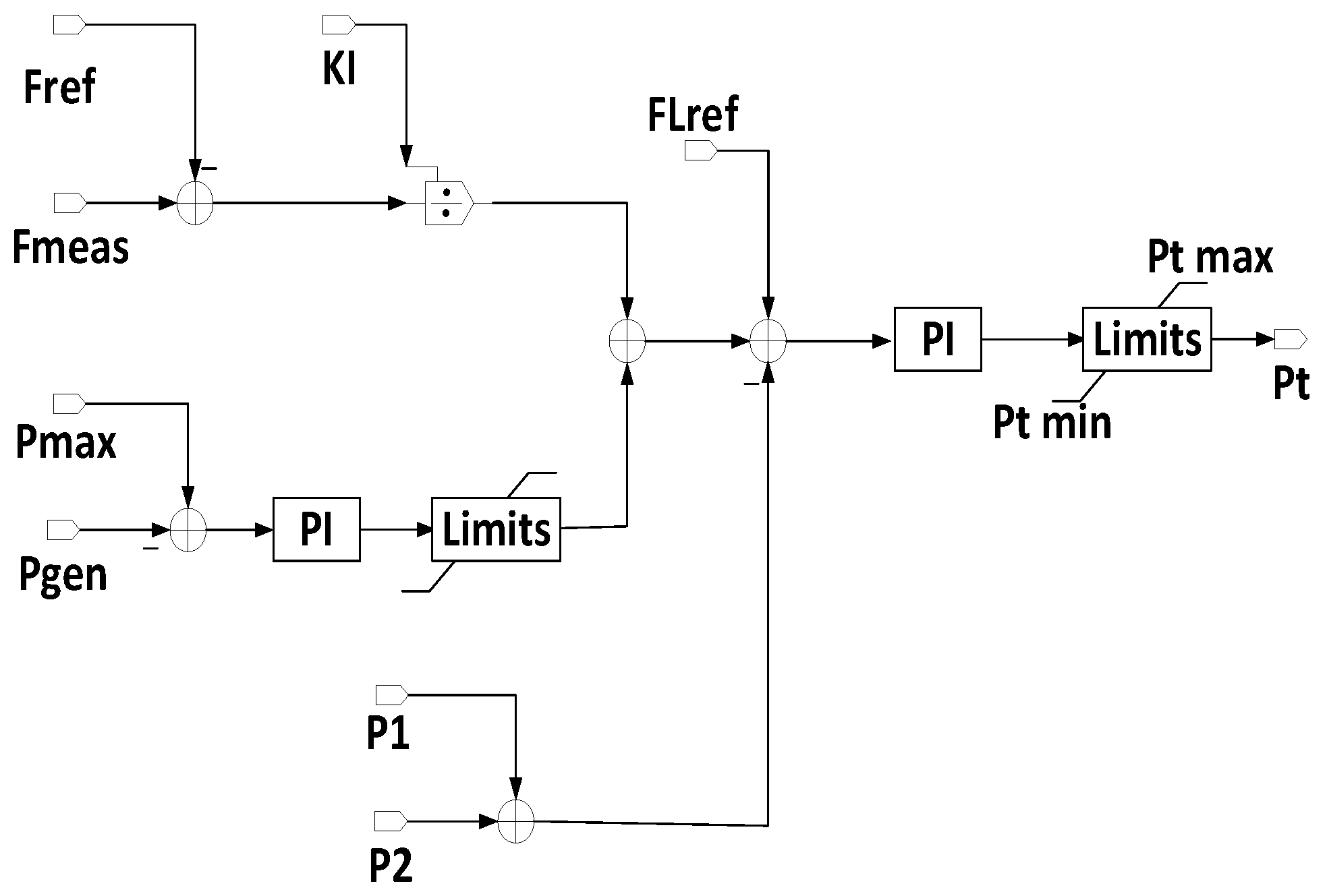
While a micro grid is connected to the main grid, the interconnection flow control looks at the active power flow from all the interconnections, sums them within its controller and compares this with a reference value. If the sum of the active power flow is different from the reference value, each DDGU will react according to its KI (gain of the PI controller) value. A dead band can also be introduced in the model to allow the sum of the active power flow to remain within a specific range. Any load variations within the micro grid will also be compensated for by the local DDGUs. If any of the DDGU trips, the others will respond accordingly to ensure that the sum of real power flow over interconnections remains constant. This is a huge advantage over FFC mode of operation, where every DDGU is only responding to the changes on their own feeder flow.
While the micro grid is isolated, it replicates the UPC mode of operation. A conventional power versus frequency (P—f) droop controller is adopted and power is shared among the units according to the droop controller constants, as defined above. With reference to
Figure 3, the IFC mode can be explained using Equations (3) and (4) below. The controller design of IFC mode is shown in
Figure 4.
5. Simulations Results and Discussions
In this section, three case studies are presented to verify the robustness of the proposed approach, as outlined below.
5.1. Case Study-1, Load Variations
In this case study, the below events were simulated:
At t = 1.2 s, Load 1 (close to SG1) is ramped down 20% in 0.2 s.
At t = 6 s, Load 3 (close to SG3) was ramped up 33% in 0.2 s.
As shown in the simulation results in
Figure 7, all the load variations were compensated for by the DDGUs even when the micro grid was connected to the main grid, keeping the sum of real power flow from the main grid at a constant value. It can be seen that the power flow over the two interconnection lines varied marginally, but the sum of flow from the main grid remained constant. The main grid maintained the frequency at a constant level and therefore the P—f droop portion of the governor controller remained ineffective for all the variations of the load and subsequent dispatch variations.
It is evident from the results that for a reduction of 0.6 MW (Load 1) at t = 0.2 s, all the DDGUs reduce their real power output in proportion to their capacities. This behavior is specific to the IFC-proposed method of active power sharing, as any load variation within the micro grid is compensated for by all the DDGUs. If DDGUs operated in the FFC mode instead of the proposed IFC, then only G1 would have adjusted its real power output. This flexibility of the IFC mode provides more room for load/generation variations as compared to FFC mode of operation. Similarly, when the same amount of load (0.6 MW) is increased at a different location (Load 3) within the micro grid, at t = 0.6 s, all DDGUs return back to their initial values of real power output. This adjustment in generation took place without causing limiting the flow of any internal line while maintaining the sum of real power flow over the interconnection lines at a constant value. It is to be noted that Load 3 increased from 1.8 MW to 2.4 MW, while the closest DDGU (SG3) is rated at 2.5 MVA. If SG3 had compensated for all the load variations within its feeder, as in case of FFC mode, then the real output power of SG3 should be raised to the maximum (100%), leaving no room for any more positive load variations within its feeder. However, in the IFC operational mode, with SG3 being smallest unit, it contributes to only around 17% of the overall load variation and is finally loaded to only up to 50% of its capacity. This provides ample room to compensate for any other positive load variations within the entire micro grid.
The final values of the real power flow over the two interconnection lines are different from their initial values, while the DDGUs returned to their initial values of real power generation. This change in flow was attributed to the change in load distribution within the micro grid. After two load-variation events, the overall load or demand of the micro grid returned to the initial value, but these variations were simulated at different locations, thereby causing the real power flow over the interconnection lines to take different final value. Using IFC mode of operation makes DDGUs, within a micro grid, insensitive to the location of variations, as they all contribute to compensate for any load/generation variations anywhere within the micro grid.
5.2. Case Study-2, Load Variations with Grid Disconnection
In this case study, the below events were simulated:
At t = 1.2 s, Load 1 (close to SG1) is ramped down 20% in 0.2 s.
At t = 4 s, Line 1 is taken out of service.
At t = 6 s, Load 3 (close to SG3) is ramped up 33% in 0.2 s.
At t = 8 s, Line 2 is taken out of service and the micro grid is isolated from the main grid.
Starting from the same initial conditions as the previous case study, Case study 2 tests the performance of the proposed IFC mode of operation under stepwise isolation from the main grid during load variations. As shown in
Figure 8, the first event replicates the negative load variation as in Case 1. When Line 1 is tripped at t = 4 s, the overall real power flow from the main grid remains at a constant value as the flow for the other line (line 1) increases. DDGUs return to their previous real power output values after a transient spike. It can be observed that SG1 and SG3 experience opposite spikes. Furthermore, SG1, being close to load 1, initially increased its real power output at the tripping of line 1. At the time of tripping, line 1 carried around 0.7 MW. A positive spike in the generated power profile of SG1 caused a negative spike in the real power flow from the main grid, however, the flow from the main grid instantly returned to the initial value due to the negative spike in the real power generation of SG3, which instantly compensated for the positive spike of SG1. At t = 6 s, when load 3 increased, introducing a positive load variation of the same value as in the first event, the real power flow (import) from the main grid remained at the same value, even with only one active interconnection (line 2) from the main grid. The three DDGUs contributed to compensating for any load variations anywhere within the micro grid. This is a key advantage of the IFC model as compared to other modes of operations, especially FFC. This also depicts the effectiveness of the IFC mode of operation for the micro grids with multiple interconnections with the main grid.
When the micro grid is completely isolated from the main grid at t = 8 s, the frequency tends to decrease to increase the power generation from the DDGUs as the real flow from the main grid drops to zero. As explained earlier, while completely isolated from the main grid, the IFC mode of operation acts similarly to the UPC mode of operation. The change in the frequency can be calculated as follows:
where:
= −0.4, FL
REF = 0.01414 (per unit on 100 MVA base) and FL
0 = 0 (as micro grid is isolated).
5.3. Case Study-3 Load Variations with DDGU Tripping
The following events were simulated for this case study:
At t = 1.2 s, load 1 (close to SG1) is ramped down 20% in 0.2 s.
At t = 4 s, line 1 is taken out of service.
At t = 6 s, load 3 (close to SG3) is ramped up 33% in 0.2 s.
At t = 8 s, SG3 is tripped.
This case study examined the capability of the proposed IFC mode of operation to cope with the loss of one DDGU within the micro grid. The first three simulated events were similar to those in Case study 2, while the fourth simulated event at t = 8 s introduced a tripping event of one generation unit.
As shown in
Figure 9, the remaining two DDGUs were able to keep the real power flow from the main grid at a constant value even after losing one interconnection (line 1) and one DDGU (SG3). Since the micro grid was not completely isolated from the main grid, the main grid was able to maintain the frequency at a constant value. Before the time of tripping (t = 8 s), SG3 generated around 1.2 MW, which is close to 18% of the overall demand of the micro grid. The loss of SG3 caused a transient spike on the real power flow on the only active interconnection line (line 2) from the main grid, however, the subsequent and timely response from SG1 and SG2 reduced the flow from the main grid back to its initial value.
Since the IFC mode of operation allows all active DDGUs to respond to load/generation variations within the micro grid as a single large virtual unit, it is able to maintain the flow from the main grid at a constant value. This could not be achieved with the FFC mode of operation, as it restricts DDGUs to respond to only load/generation variations within their feeders.
With the results attest to the fact that in the proposed IFC mode of operation, a micro grid can sustain two severe contingencies without losing its ideal operation, that is to act as either a constant load or source to the main grid.


