1. Introduction
One of the tasks related to the design and calculations of power plants based on fuel cells with proton exchange membranes (PEMFC) is the construction of an equivalent PEMFC scheme and the determination of its parameters. Different variants have been proposed to solve this problem. However, none of the methods known to us takes into account the influence of eddy currents that occur in metal electrodes and other conductive parts of the PEMFC structure due to the flow of the alternating high-frequency component of the current. This component inevitably arises due to the operation of semiconductor voltage converters, which, as a rule, are connected to the PEMFC. Thus, the problem consists in constructing an equivalent PEMFC scheme that takes into account eddy currents, and also in determining the parameters of this scheme.
The influence of eddy currents on the electrical processes in the PEMFC and the devices connected to it may be weak or significant, depending on the parameters of the circuit elements. At the same time, voltage and current overloads are possible, which is critically important to exclude at the stage of calculation and design of the product. Eddy currents dampen electrical oscillations and also lead to energy losses and heating. It is important to be able to calculate these phenomena at least to assess their significance in specific cases. If the influence of eddy currents is significant, then it should be taken into account and adjusted if necessary. In addition, the calculations of the PEMFC, taking into account eddy currents, are of theoretical scientific interest.
The development of an equivalent scheme of the PEMFC, taking into account the influence of eddy currents, seems to be a difficult task, primarily because it requires a new look at the known and studied device. At the same time, it is important to correctly identify and take into account all significant physical factors. A separate task is the practical determination of the values of the parameters of an equivalent scheme. Solving this problem required ingenuity and original approaches to the experimental and computational part. In particular, it was necessary to consider transients occurring at different speeds.
The exact reason why this task was not solved earlier is unknown to us. It can be assumed that the presence of eddy currents did not attract the attention of researchers for the reason that the PEMFC is traditionally considered as a source of direct current. Moreover, the effect of eddy currents is not always noticeable in practice. Traditional equivalent schemes of a PEMFC usually consist of two or three resistors and only one capacitor (for example, [
1]). Such schemes are suitable for calculating slow transients. Some known equivalent schemes also contain an inductor [
2]. Such schemes can be used to simulate slow and fast processes, but they do not take into account energy losses caused by eddy currents in conducting elements. These losses in some modes can lead to a significant damping of electrical oscillations and the additional heating of the PEMFC.
A key component of our approach is to take into account the alternating high-frequency component of the current of the PEMFC. In particular, it takes into account the influence of eddy currents caused by this component. Another important feature is the use of fast–flowing and slow transients separately to determine the parameters of an equivalent PEMFC scheme. A key component of the results can be called the possibility of correct numerical modeling of processes in the PEMFC and associated circuits at the design stage. This makes it possible to avoid the electrical and thermal overloads of components and create a reliable product. The main results of the work are also the proposed new equivalent scheme of the PEMFC and the original practical method for determining parameters.
With the help of the numerical simulation of the PEMFC with a voltage converter connected to it and a load on the examples presented in the article, it is confirmed that with some combinations of circuit parameters, the action of eddy currents in the conductive structural elements can noticeably dampen oscillations, as well as increase energy losses and heat generation in the PEMFC. A comparison of the calculated and experimental data for the control experiment shows an excellent correspondence.
The new knowledge provided by the proposed article consists in the developed equivalent scheme of the PEMFC, which, in contrast to the known schemes, takes into account the influence of eddy currents in the conductive elements of the structure. The new results also include a practical experimental and computational method for determining the parameters of this scheme. This knowledge and these results are confirmed by examples of the numerical calculation of electrical circuits and fill the existing gap in the theory and methods of modeling of the PEMFC.
2. Equivalent Scheme
This research was initiated by the problem of creating a PEMFC-based power supply system for a small (1–2 kW power) unmanned aerial vehicle (UAV). Peak loads during maneuvers accompanied by changes of the fuel cell current are the specific feature of the operating modes of the UAV power plant. To solve this problem, special voltage stabilization circuits are used in the integration mode of the PEMFC stack and the battery [
3,
4,
5,
6,
7]. In this case, a low-frequency part of the fuel cell alternating-current component, which is formed in transient modes when the load changes, is mostly compensated by battery connected in parallel with the load and with the help of a regulator that controls the voltage converter. The main high-frequency part of the fuel cell alternating-current component is caused by the operation of the voltage converter, although this fact is not found in the publications known [
1,
7,
8,
9,
10,
11,
12,
13,
14,
15,
16,
17,
18].
It is possible to develop UAV electrical complex with the help of mathematical and computer modeling methods, to be more exact, by creating models of power plant subsystems, including the fuel cell to further combine them into a generalized computer model. This allows predicting the electrical complex parameters and characteristics at the design stage, considering electrical processes in the fuel cell, and setting the requirements for control algorithms.
The voltage at PEMFC output significantly depends on the load current [
8]. A fuel cell stack requires voltage and current stabilization in the range of about 70–110% of the nominal value. As mentioned above, such modes are provided by step-down transformerless converters [
9,
10,
11,
12,
13,
14,
15] and batteries connected in parallel with the load and operating in a buffer mode. The converters consume current from PEMFC battery, containing DC and high-frequency pulse components. DC component generation is a regular function of the PEMFC. The influence of the alternating impulse current component on PEMFC operating modes has not yet been sufficiently studied. Therefore, these issues are raised in this paper.
The study of the alternating current effect on PEMFC implies two aspects. The first is the study of possible changes in chemical reactions under the alternating current. This task falls within the electrochemistry field. The second is the study of PEMFC response to alternating current as an electrical circuit element. This task may be attributed to the competence of theoretical and applied electrical engineering.
Another important design task is the calculation of overloads of circuit elements by voltage and current. It is recommended to solve this problem for the entire system, as its processes differ significantly in characteristic frequencies and time constants. In this case, the synchronization of peak loads from different frequencies may cause a critical overload. The system is complicated, so ordinary engineering intuition and experience may not be sufficient to create a reliable operating device. It is easier and cheaper to perform the required tests first on a numerical model and then on a full-scale specimen.
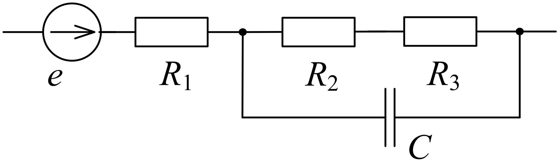
Most of the known equivalent schemes consist of resistors and capacitor (
Figure 1). Such circuits might be used only to model low-frequency (less than 1 Hz) periodical processes or transient processes with big (more than 1 s) time constants because capacitance
C is very high (several farads). Real PEMFC work with high (10 kHz and above) frequencies.
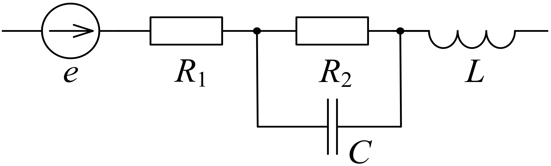
Some existing equivalent schemes contain an inductor (
Figure 2). This makes it possible to model high frequency periodical processes and fast transient processes. On the other hand, such schemes do not take into account power losses caused by eddy currents in metal plates and other conductive elements. If there is alternating and especially high frequency current in conductors, it initiates eddy currents caused by the time variation of magnet field created by primary current. The influence of these eddy currents may be significant in some cases and should not be neglected.
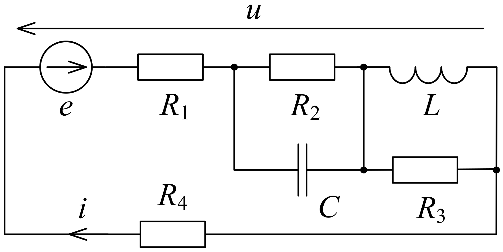
The authors propose an option of the fuel cell dynamic equivalent scheme, shown in
Figure 3. Electromotive force
e is the equivalent fuel cell EMF;
C is the capacity generated by the electrochemical effect of double layer of electric charges at the interface between electrodes and the proton-conducting membrane;
L is the parasitic inductance of PEMFC circuit;
R1 is active internal resistance of the PEMFC caused by specific ohmic resistance of the conductors;
R2 is resistance simulating the energy losses due to polarization activation inside PEMFC;
R3 is active dynamic resistance for modelling energy losses from eddy currents in metal electrode plates and other conductors; and
R4 is the load resistance.
The scheme with dynamic losses effect reflects the physical reality; resistor
R3 with parallel inductance does not prevent flow of current
i steady component, but it dampens the alternating component of this current. Eddy currents arise due to magnetic field variations generated by the main current. The equivalent scheme parameters are determined by experimental data. The difference of this circuit in comparison to the more widely used types [
1,
2,
16,
17,
18] mainly consists in the influence of dynamic losses in conductors. Obviously, this influence is present and might be quite significant if caused by rapidly changing large currents. However, the authors are not aware of any papers which consider or mention such an issue. Eddy currents dampen electrical oscillations in the PEMFC circuit, absorbing energy and causing heating. In some operating modes with certain parameters of the power plant, their influence can be negligible, but it can be of importance in other modes and with other parameters.
3. Equivalent Scheme Parameters Evaluation
The PEMFC equivalent scheme parameters might be determined as follows. Electromotive force
e and the sum of resistances
R1 +
R2 can be obtained from the solution of the system of equations according to the results of two experiments on PEMFC stack loading with direct current within approximate linearity of the V-I characteristic (Equation (1)):
where
u1,
u2 are PEMFC voltages, and
i1,
i2 are corresponding currents at different loads
R41 and
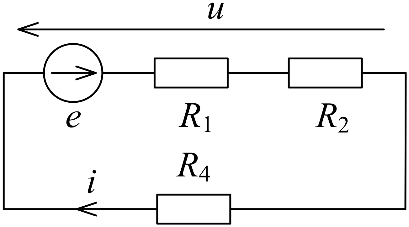
R42. When loaded with direct current, inductance
L, resistor
R3, and capacitor
C are excluded from the circuit (
Figure 4). It makes no practical sense to model PEMFC either at very low or very high currents in the non-linear sections of its V-I characteristic since the PEMFC does not operate in such modes. In the analyzed experiments, PEMFC is loaded directly with the
R4 resistor without voltage converter. To improve the accuracy and reduce the influence of random errors, instead of solving system (1), one can determine the same parameters
e and
R1 +
R2 from several points of experimental V-I characteristic of PEMFC stack by the least squares method. For PEMFC prototype, with 1/4 of the working fuel cell installed on the experimental UAV, the following values are obtained:
u1 = 20.0 V;
u2 = 14.8 V;
i1 = 2.0 A; and
i2 = 16.0 A. The parameters
e = 20.743 V and
R12 =
R1 +
R2 = 0.371 Ohm are calculated based on the mentioned values.
For further studies, we use stiffness of the equation system to describe transients in the dynamic equivalent scheme shown in
Figure 3. Experimental data and calculated estimates show that the duration of transient associated with the inductance
L is about three orders of magnitude shorter than the duration of process with capacitance
C. It makes it possible to study these processes separately. We will change the load resistance abruptly from high value
R41 = 10 Ohm to low value
R42 = 0.938 Ohm (load rise). The same resistances were used to determine PEMFC static parameters.
It is necessary to consider the state of the circuit right after the end of the fast transient associated with inductance. During this time, the voltage across the capacitor cannot significantly change its value, resistor
R3 will be practically shunted by inductance
L as the transient process with the inductance is completed. Therefore, the jump of the load voltage (
Figure 5) is related to the changing current in the resistor
R1 (Equation (2)):
By the current limiting value on the right, we get its value immediately after the end of the transient process with inductance.
In the experiment with the resistive load rising, a voltage surge Δ
u = 1.3 V was got with current limiting values of
i(−0) = 2.0 A;
i(+0) = 20.0 A. At load shedding, respectively, Δ
u = 1.0 V;
i(−0) = 16.0 A;
i(+0) = 2.0 A. Calculated resistance values
R1 are, respectively, equal to 0.072 Ohm and 0.071 Ohm. For further calculations,
R1 = 0.071 Ohm. As
R12 =
R1 +
R2 = 0.371 Ohm, we determine
R2 = 0.3 Ohm. For voltage change curves, we define approximations by calculating the time constants by solving non-linear equations
S = 0 using the dichotomy method, where
S is the average deviation of the approximation from the experimental data in the active phase of the transient process. For load rising, we obtain the function (Equation (3))
for shedding (Equation (4))
It is clear that the time constant for the circuit shown in
Figure 3, without inductance
L and resistor
R3, is equal to τ =
C·
R2·(
R1 +
R4) ÷ (
R1 +
R4 +
R2). By substituting the corresponding values of τ and resistances into this equation, it is possible to determine the capacitance
C. When the load rises, it is 0.0668 F, when the load sheds, it is 0.0734 F. For further calculations, we take the average value of
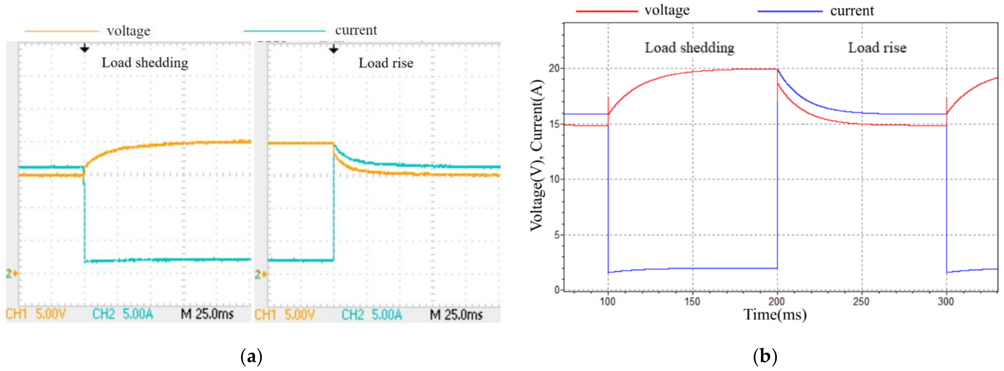
C = 0.0701 F. The experimental and calculated time dependences of PEMFC voltage and current are demonstrated in
Figure 6.
The calculations were performed with the “Electroscope” program, created by the authors of this paper. Its description is presented in [
19]. The program is characterized by an increased reliability in calculations of circuits with commutations.
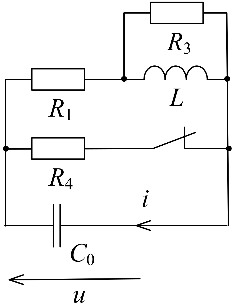
In the equivalent scheme, it is also necessary to determine inductance
L and resistance
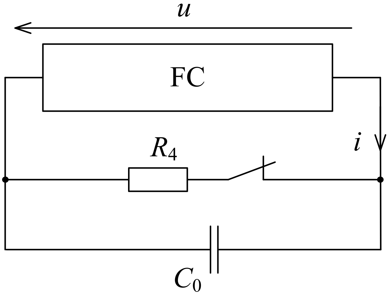
R3. The experimental design to determine these parameters is shown in
Figure 7.
An additional test capacitor
C0 has much lower capacity than the capacitor
C. This is why during the transient process of the capacitor C
0 charging, voltage across the capacitor
C changes insignificantly. Practically, it works as a voltage source, and the equivalent scheme for the free component of this transient process is as shown in
Figure 8.
After opening the key, resistor R4 is excluded from the circuit. The capacitor C0 = 1.768 μF is selected so that the transient process is oscillatory. The characteristic equation for the resulting circuit is as follows: (R1 + R3)·L·C0·p2 + (R1·R3·C0 + L)p + R3 = 0.
The equation solution can be represented as
p1 = −δ +
jω,
p1 = −δ −
jω, where
These equations can be converted to two linear equations for
L and
R3. As result of solving the equations, these two parameters are determined if all the others are known:
The values of δ and ω can be determined from the digital oscillogram using any optimization method because the solution of the problem does not depend on the used solving method. The target function can be norm of the difference between the experimental data and the approximation of the form
u(
t) =
Aexp(−δ(
t −
t0))cos(ω(
t −
t0)). Resistance to and the reactance of the conductor with alternating currents depend on the frequency [
20], which, apparently, can be observed on the oscillogram. The time dependence of circuit parameters can be taken into account by constructing a more complex active-inductive equivalent scheme, but in terms of this paper we refer to the first approximation in the form of one inductance
L and one resistor
R3. For more complicated equivalent schemes, it is not yet possible to obtain circuit parameters using simple formulae.
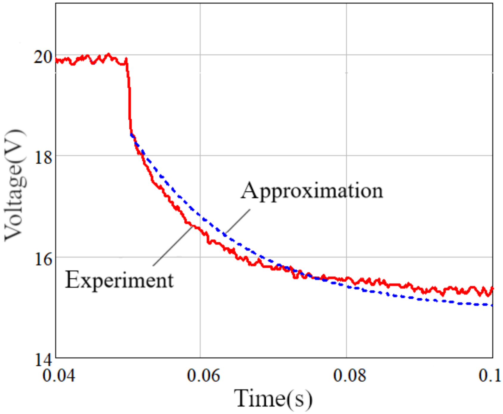
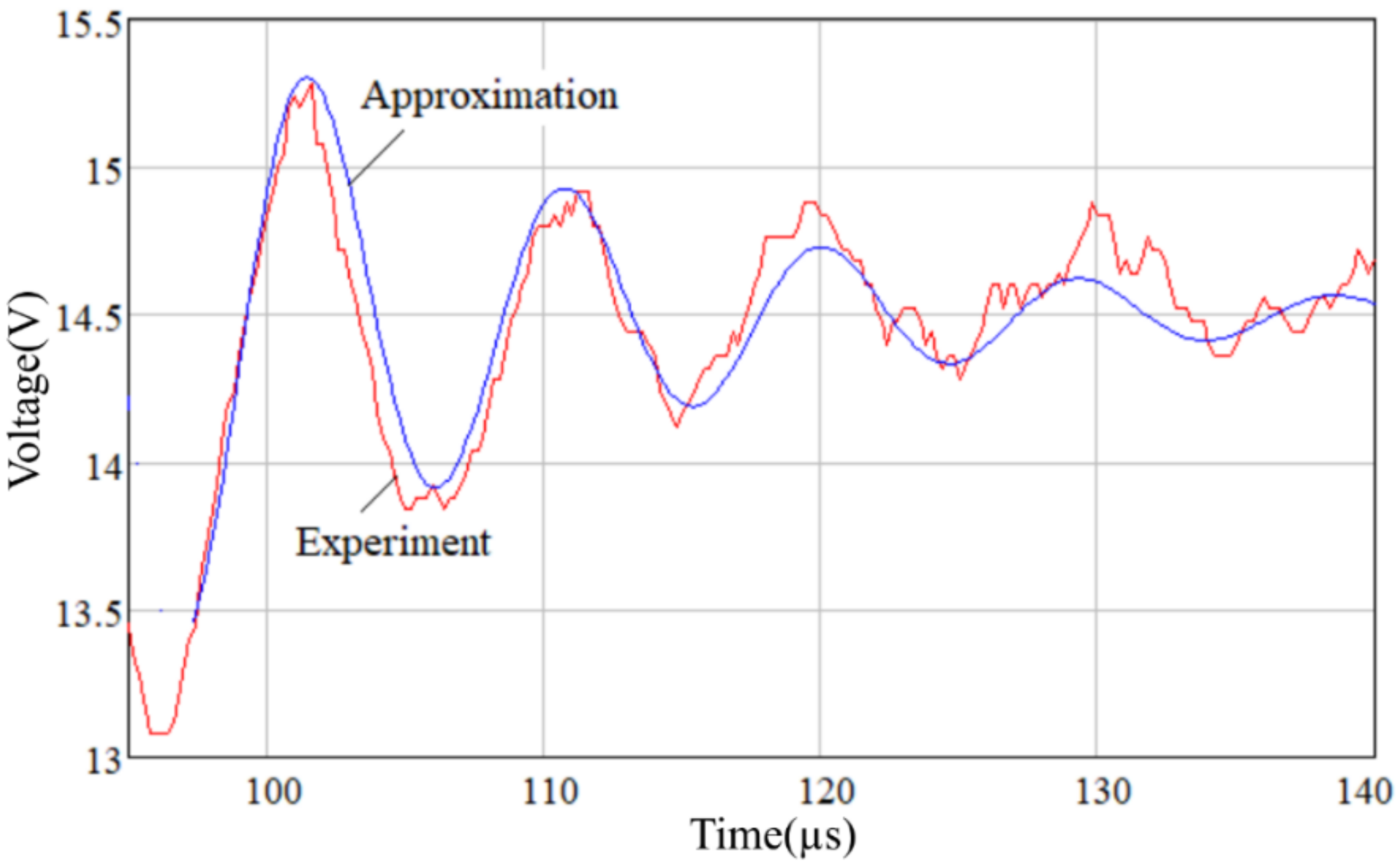
The experimental oscillogram of the voltage across the capacitor
C0 when load the
R4 switches off and its approximation are shown in
Figure 9. From this oscillogram that was taken from the oscilloscope in digital form, in accordance with the coordinate descent method, values δ = 6.724 × 10
4 1/s and ω = 6.774 × 10
5 rad/s are calculated, the time interval varies from 101.6 to 150 μs. However, due to the fact that the frequency and attenuation coefficient of the experimental data change during the transient process, these values need to be specified. To improve approximation accuracy, they are corrected according to the graph. As a result, the approximate values of transient process parameters δ = 5.263 × 10
4 1/s and ω = 6.68 × 10
5 rad/s are obtained. According to the formulae above, the circuit parameters are as follows:
L = 1.252 μH and
R3 = 12.737 Ohm. The calculations consider the equivalent series resistance of the capacitor (ESR) 6 mOhm. This resistance ESR, as well as equivalent resistance
R1, has a noticeable effect on the parameter values.
Using the known parameters of the PEMFC equivalent scheme, it is possible to calculate the options for power plant operating modes, select the parameters of its elements that provide the specified energy indicators. The calculation of the voltage and current overloads of semiconductor elements is critically important; this calculation is impossible without an adequate equivalent scheme for PEMFC in transient modes. In this case, it is important to consider circuit inductance and oscillation damping. Without full consideration of these factors, numerical modeling results may differ from the real device processes.
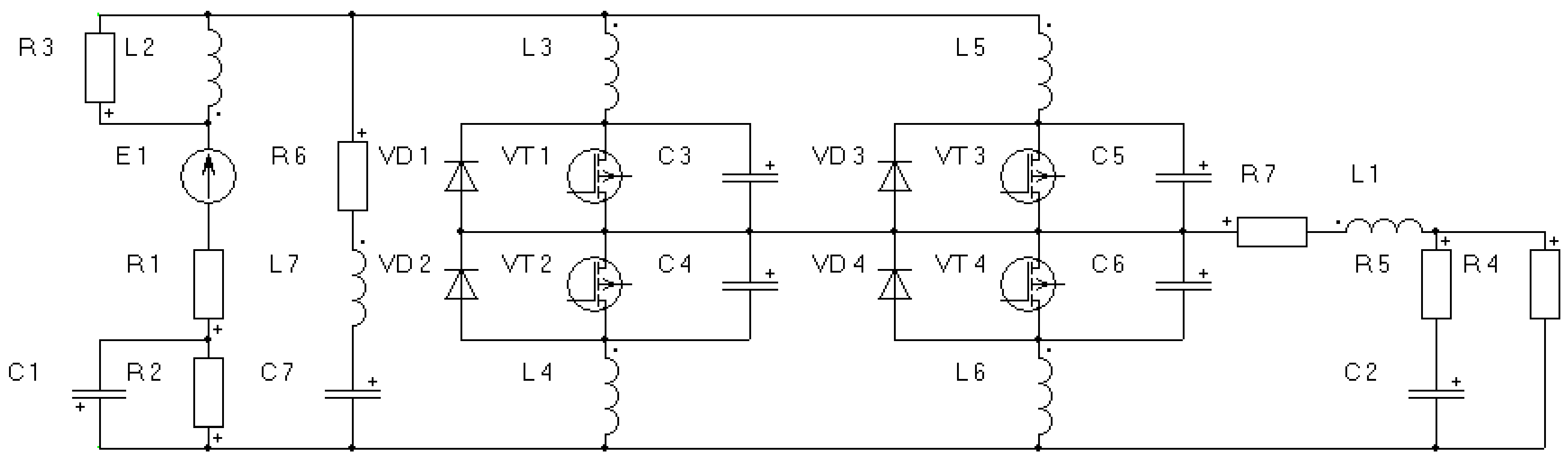
To illustrate the PEMFC model features, let us consider the power plant electrical complex based on PEMFC, shown in
Figure 10. One of the design stage tasks is to determine the capacitance of capacitor
C7, connected in parallel to the PEMFC to quench overvoltages on the semiconductor switches. These overvoltages arise due to the interruption of currents in the two-wire line connecting PEMFC and voltage converter. Since this line and the PEMFC itself have parasitic inductances and the rate of current change is very high, in the absence of a capacitor, overvoltages result in additional thermal losses in the keys and the possible electrical breakdown of semiconductor devices. A justified choice of the capacitance
C7 is possible only by using numerical modeling.
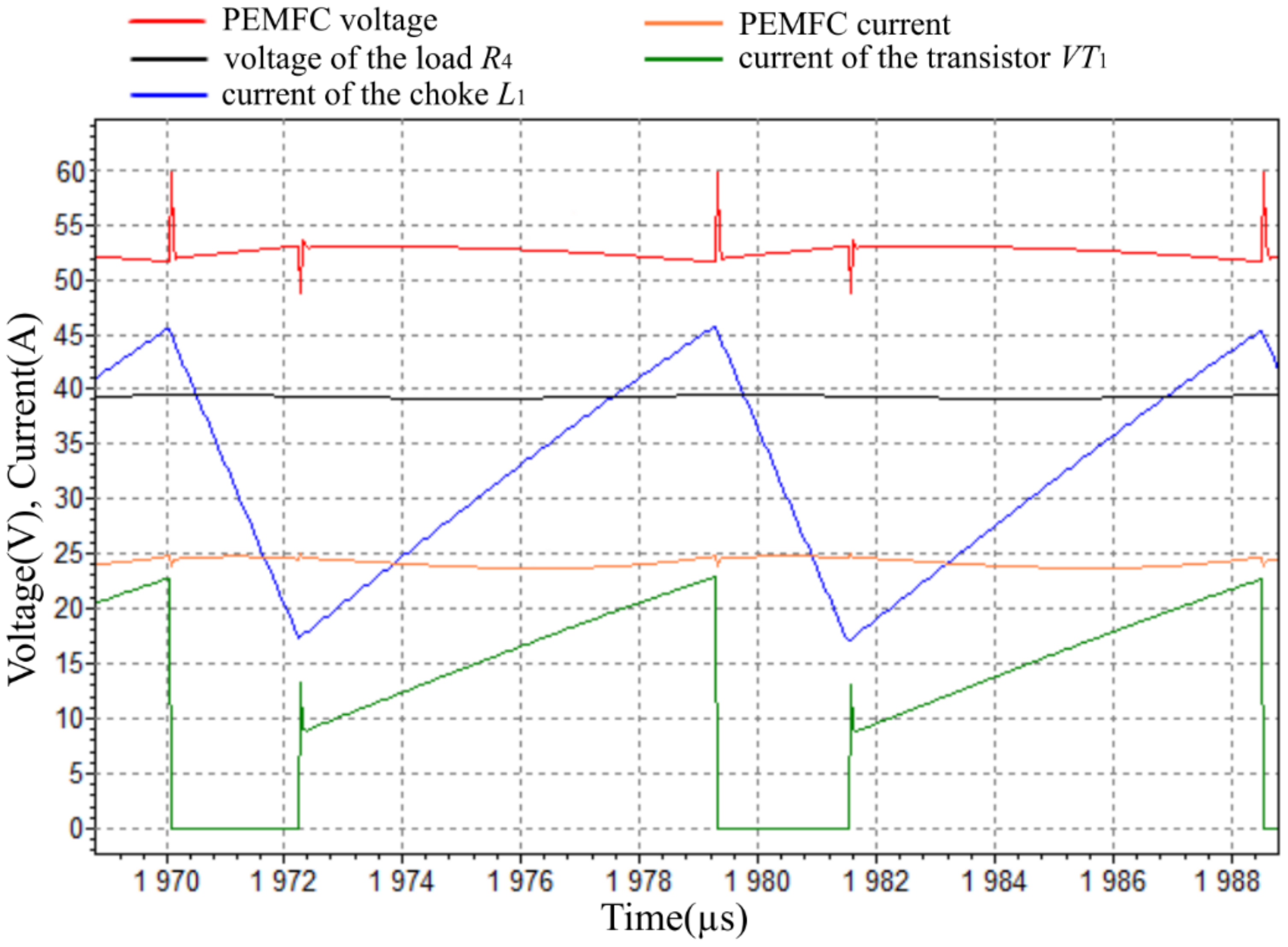
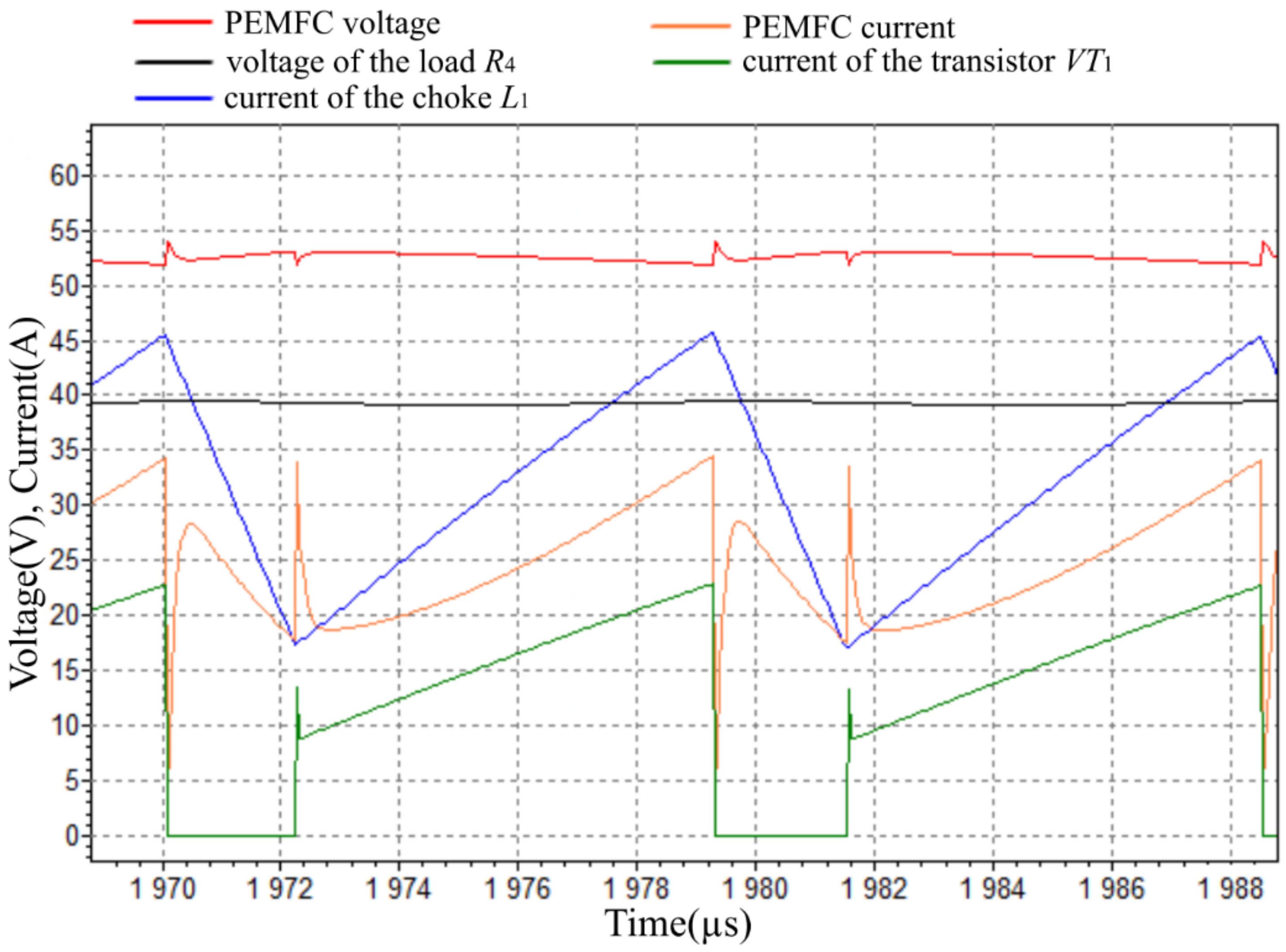
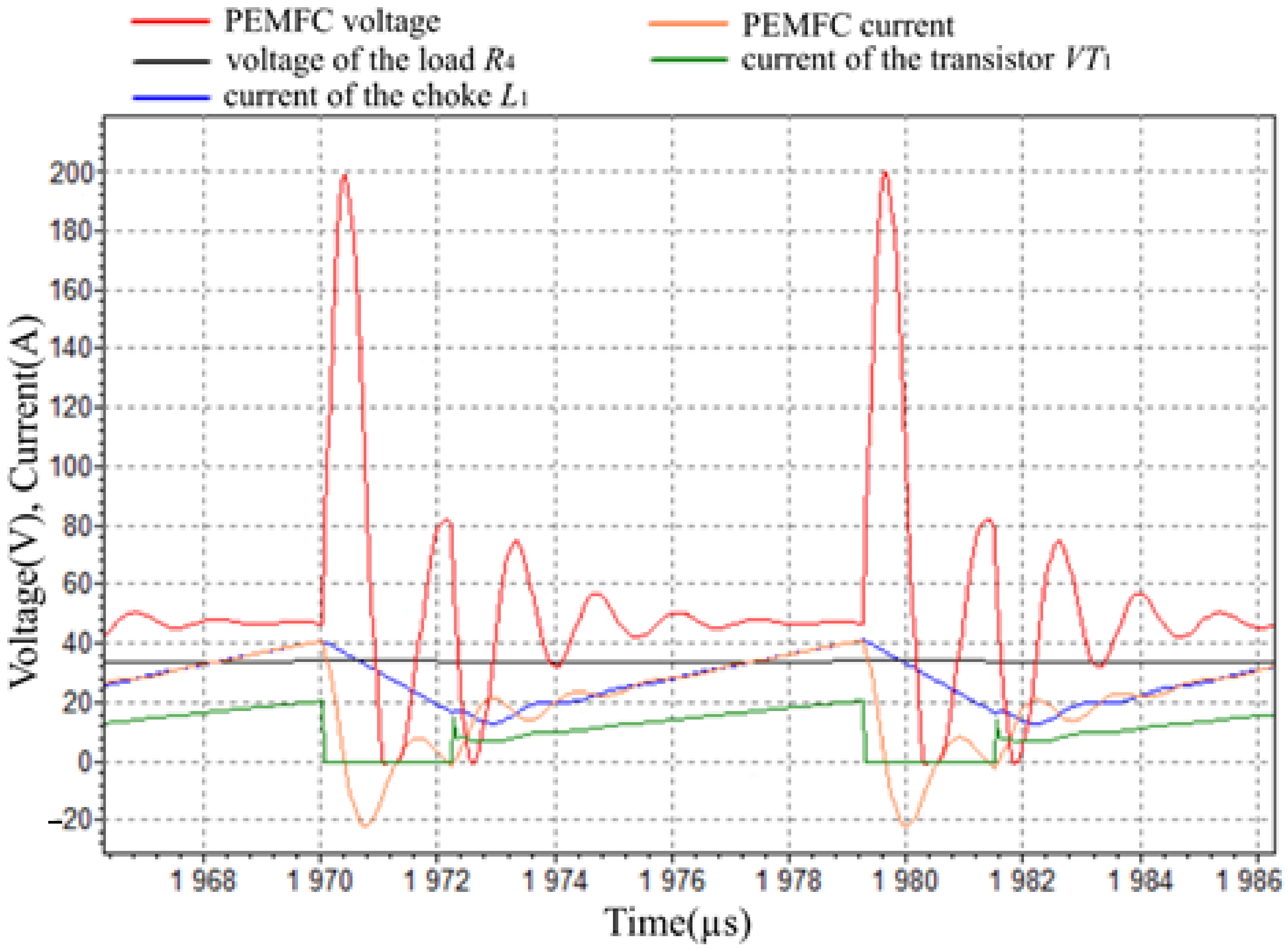
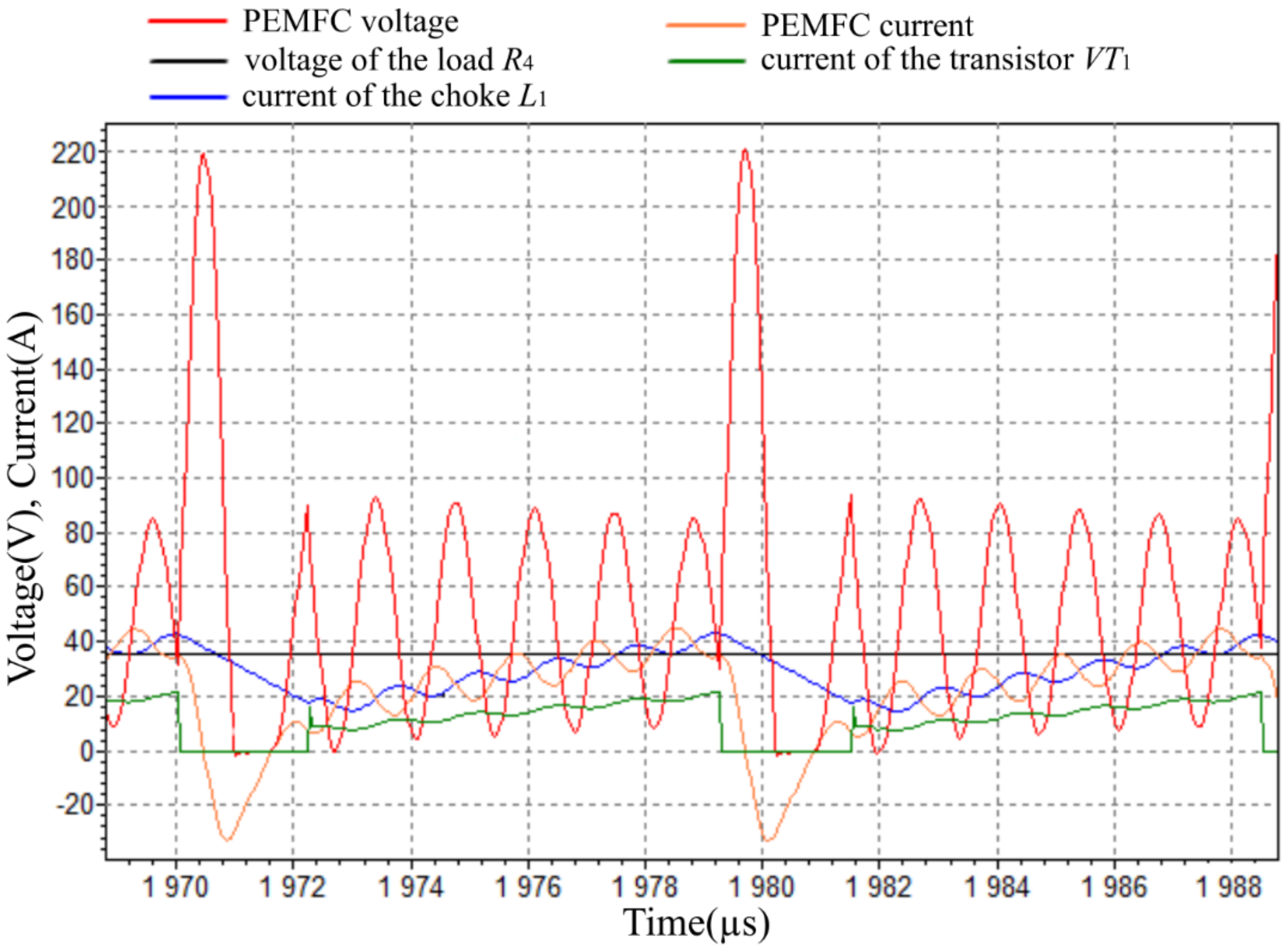
Figure 11,
Figure 12,
Figure 13 and
Figure 14 present the calculated oscillograms showing the effect of the capacitance
C7 and the active-inductive part of equivalent scheme on PEMFC operation with 1250 W resistive load.
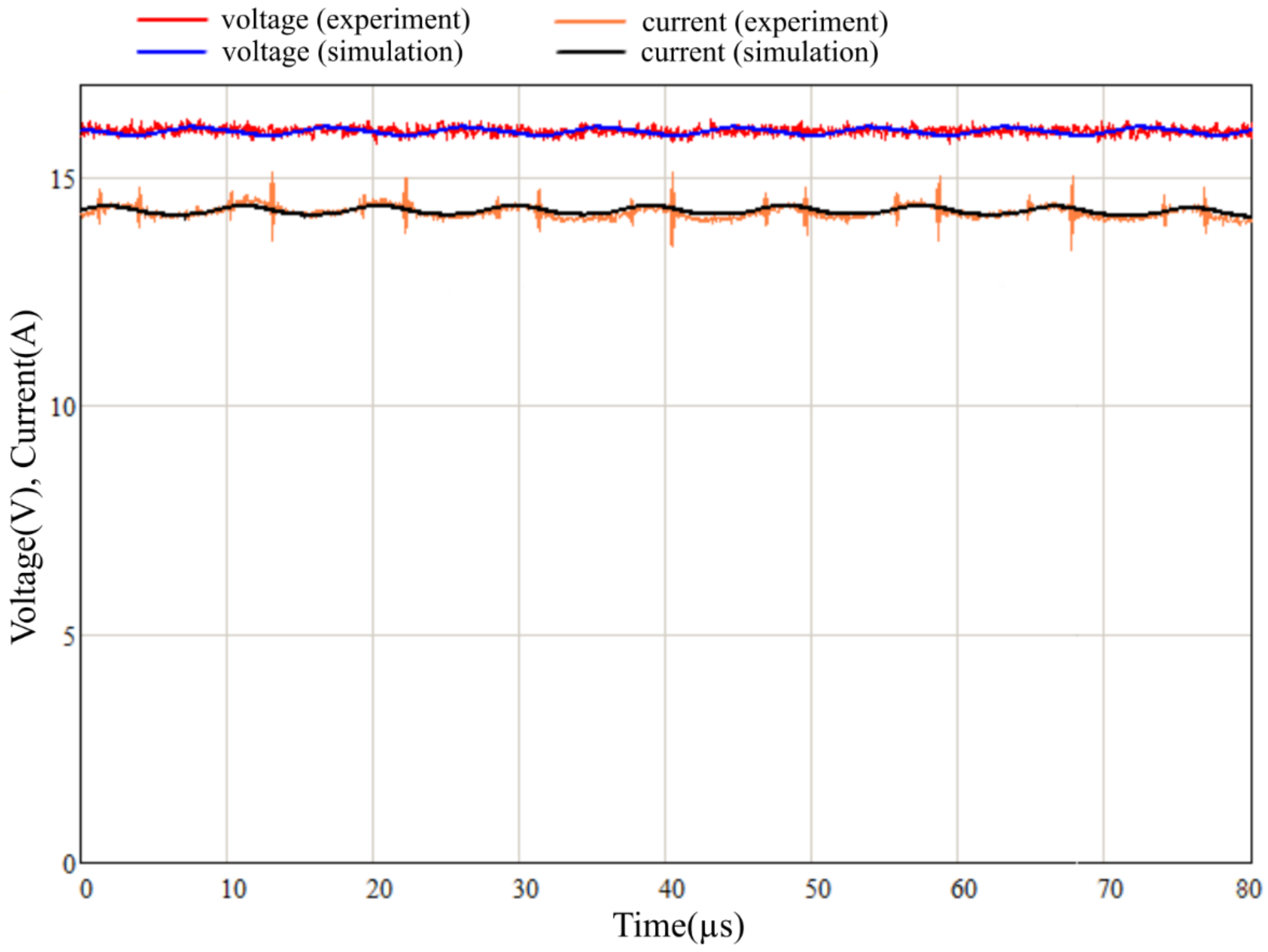
Figure 15 shows voltage and current of the PEMFC with converter and 224 W resistive load, simulation, and experimental results. Calculations are performed in the “Electroscope” program.
4. Results and Discussion
The first result of the presented research is a new model of PEMFC, which, in addition to the phenomena traditionally taken into account, takes into account eddy currents in metal electrodes and other conductive structural elements. Taking into account eddy currents seems natural and necessary, since they are necessarily induced in any conducting bodies in the presence of an alternating electromagnetic field. In the case of PEMFC, eddy currents are excited by the high-frequency component of the current, which arises as a result of the operation of voltage converters commonly used together with PEMFC.
The fact that up to now the calculations of circuits with PEMFC have been carried out without taking into account eddy currents suggests that in many practical cases the effect of these currents is weak. However, as the comparison of
Figure 13 and
Figure 14 shows, for example, in some cases the influence of eddy currents can be noticeable. At least, the refusal to take into account this influence in the general case should be justified, since this phenomenon itself always takes place. Taking into account eddy currents makes the equivalent scheme of the PEMFC more accurate and correct. This leads to more adequate calculations at the product design stage and increased reliability.
The second result is an original method of practical experimental and computational determination of the values of the parameters of the proposed equivalent scheme. It allows the parameter values for circuit elements by several simple experiments and calculations to be obtained. Without this technique, the value of the scheme would not be so big. It is essential that the new equivalent scheme does not require any special laboratory equipment and complex calculations for its use. That is, the improvement of the design quality is achieved without additional costs.
The third result is the presented numerical calculations of the operating modes of the PEMFC together with the voltage converter. They show the way to use the equivalent scheme of the PEMFC, make it possible to compare operating modes with different circuit parameters. In particular, these calculations show that in some cases the action of eddy currents can be noticeable and may deserve attention. Numerical calculations also show excellent accordance with the data obtained experimentally on a real PEMFC (
Figure 15). This proves the correctness of the approaches and assessments made in the work.
5. Conclusions
The article proposes a dynamic equivalent scheme for the PEMFC, which, unlike the known schemes, takes into account eddy currents in metal plates of electrodes and other conductors. These currents affect the transients in the PEMFC circuit and the PEMFC itself. Without full consideration of this factor, the results of numerical simulation may differ from the actual processes in the device. In the studies known to us, eddy currents are not taken into account.
An original method of the experimental investigation of the PEMFC and the subsequent calculation of the parameters of the developed equivalent scheme for the PEMFC based on the results of the experiment is proposed. A study of transients in the electrical part of a power plant based on the PEMFC, taking into account the parameters of the fuel cell block, was carried out. Unlike most of the relevant studies, switchings in a step-down voltage converter are considered as the source of these processes corresponding to the actual operating conditions of the power plant. The calculations performed make it possible to determine the parameters of the power plant at the design stage and with the help of computational experiments to study the operation of the installation in various modes. The results of the numerical simulation of the power plant based on the PEMFC show an excellent correlation with experimental data.
For further work on the topic of the article, the following considerations can be considered. First, we can try to do the experiment with oscillatory transient process for determining the inductance L and resistance R3 in another way, so that the amplitude of voltage oscillations is greater.
This will reduce extraneous influences and measurement errors. This can be carried out by connecting the PEMFC to the capacitor. Before the connection, the PEMFC can be in idle mode or in normal load mode and the capacitor can be discharged or charged to some reverse polarity voltage. Secondly, numerical experiments are of interest, which would make it possible to more accurately determine the conditions under which the influence of eddy currents is noticeably manifested.


