Article

Operation Safety of a 2-DoF Planar Mechanism for Arm Rehabilitation

by
Marco Ceccarelli
1,
Matteo Russo
2,
Daniele Cafolla
3 and
Betsy D. M. Chaparro-Rico
3,*
1
LARM2: Laboratory of Robot Mechatronics, University of Rome “Tor Vergata”, 00133 Rome, Italy
2
Faculty of Engineering, University of Nottingham, Nottingham NG81BB, UK
3
Biomechatronics Lab, IRCCS Neuromed, 86077 Pozzilli, Italy
*
Author to whom correspondence should be addressed.
Inventions 2021, 6(4), 85; https://doi.org/10.3390/inventions6040085
Submission received: 28 October 2021 / Revised: 9 November 2021 / Accepted: 11 November 2021 / Published: 15 November 2021
(This article belongs to the Collection Feature Innovation Papers)

Abstract

:
The operation safety of rehabilitation devices must be addressed early in the development process and before being tested on people. In this paper, the operation safety of a 2-DoF (degrees of freedom) planar mechanism for arm rehabilitation is addressed. Then, the safety and efficiency of the device operation is assessed through the Transmission Index (TI) distribution in its workspace. Furthermore, the produced stresses on the human arm are assessed via the FEM (finite element method) when the rehabilitation device reaches five critical positions within its workspace. The TI distribution showed that the proposed design has a proper behaviour from a force transmission point of view, avoiding any singular configuration that might cause a control failure and subsequent risk for the user and supporting the user’s motion with a good efficiency throughout its operational workspace. The FEM analysis showed that Nurse operation is safe for the human arm since a negligible maximum stress of 6.55 × 10³ N/m2 is achieved by the human arm when the device is located on the evaluated critical positions.

1. Introduction

Rehabilitation robotics have contributed positively to the rehabilitation processes, speeding up recovery times[1,2] and reducing the physical fatigue of therapists. This has increased the interest in the development of medical devices for motor rehabilitation in the last decades[3,4,5,6,7]. Particularly, several devices have been developed for upper-limb rehabilitation such as exoskeleton and semi-exoskeleton devices[8,9,10,11,12,13,14]. Exoskeleton and semi-exoskeleton devices offer large workspaces and customizable exercises. However, they require large links, bulky frames, large motors, and a precise axis alignment with the upper limb joints to avoid injuries. Furthermore, the mechanisms of exoskeletons and semi-exoskeletons must be reconfigured to be used for both left and right arm or else an exoskeleton must be built for each human arm. Regarding portable mechanisms, they generally perform restricted trajectories limited by their mechanical structures[15,16,17]. Although there are portable end-effector mechanisms that can reproduce customizable trajectories[18,19] they require long links to cover most of the human arm workspace. Some cable-driven devices[20,21] offer convenient advantages regarding portability and customization of the exercises. However, the loss of tension of the cables when the patient makes an oppositional or involuntary movement is an issue that still requires further investigation. Furthermore, cable-driven devices[22] generally need to be over-actuated to maintain the cable tension. On the other hand, the 2-DoF (degrees of freedom) mechanism for upper limb rehabilitation presented in this paper, whose name is Nurse, combines a large number of advantageous features that are hard to find all together in other mechanisms. The mechanism structure of Nurse is composed of light links and a tiny frame that facilitates its portability and makes it suitable for home use. Furthermore, the linkage structure offers a large workspace without the need for large and long links. Additionally, it can reproduce customizable and varied exercises for both the left and right human arm without requiring mechanical reconfigurations.
In a previous work, the authors characterized four arm exercises[23] that were later used for a numerical characterization[24,25] and an experimental characterization[26] of Nurse. However, the operation safety of the device had not yet been addressed in[23,24,25,26]. Operation safety of the rehabilitation devices should be addressed early in the development process before the device is tested on people[27]. Therefore, the safety operation is an important issue that will be addressed in this paper.
In this paper, the Nurse device is briefly described. Next, the safety and efficiency of the NURSE operation is assessed through the Transmission Index (TI) distribution in the Nurse workspace. After that, the produced stresses on the human arm are assessed via a FEM (finite element method) when Nurse reaches five critical positions within its workspace.

2. Materials and Methods

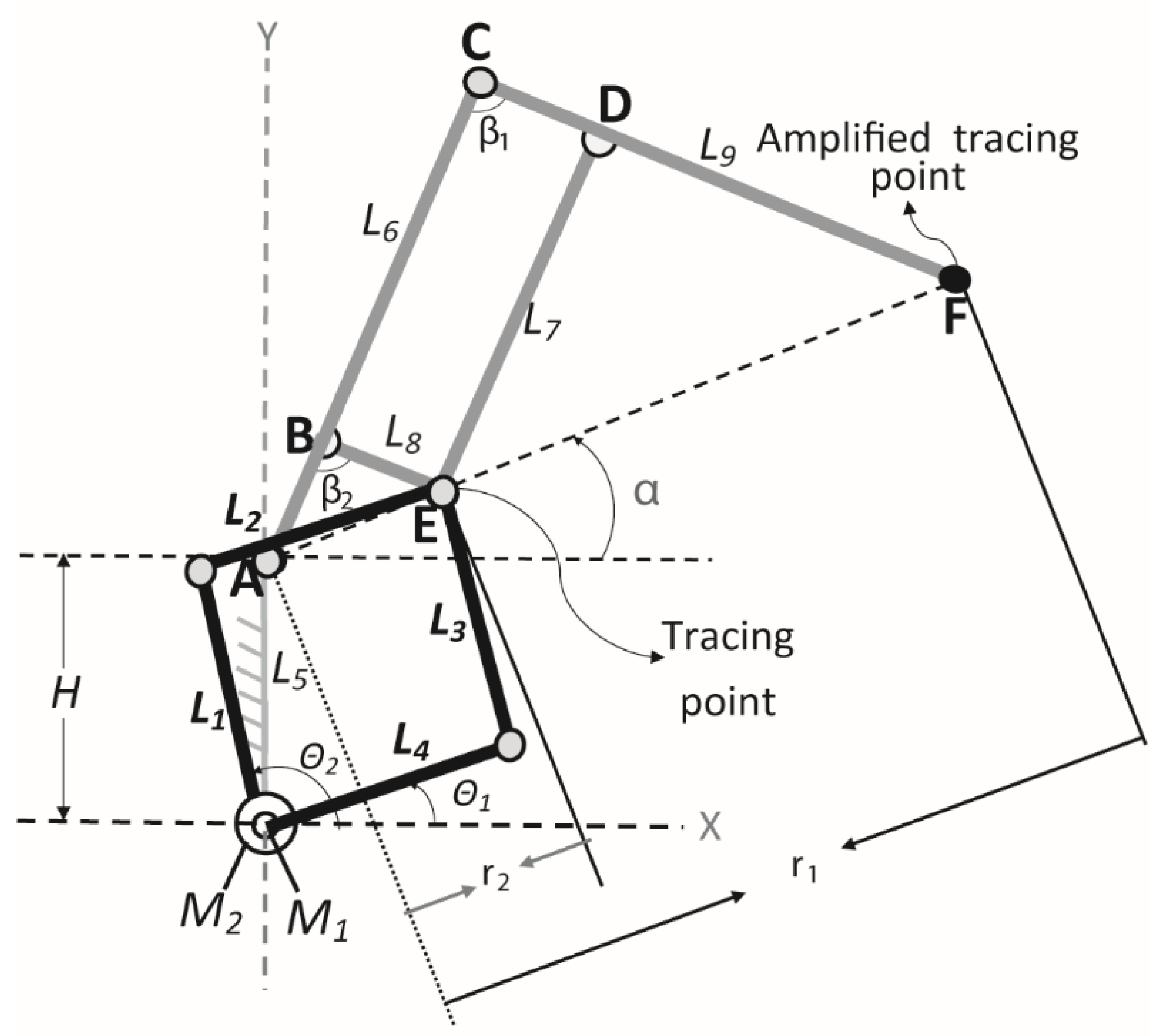
2.1. A Brief Description of Nurse

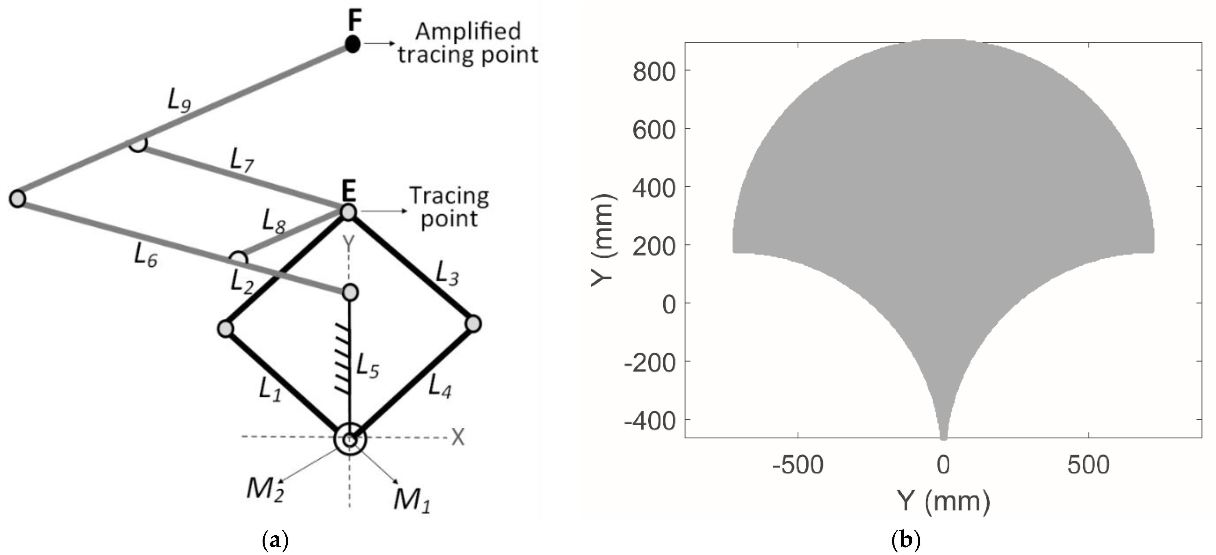
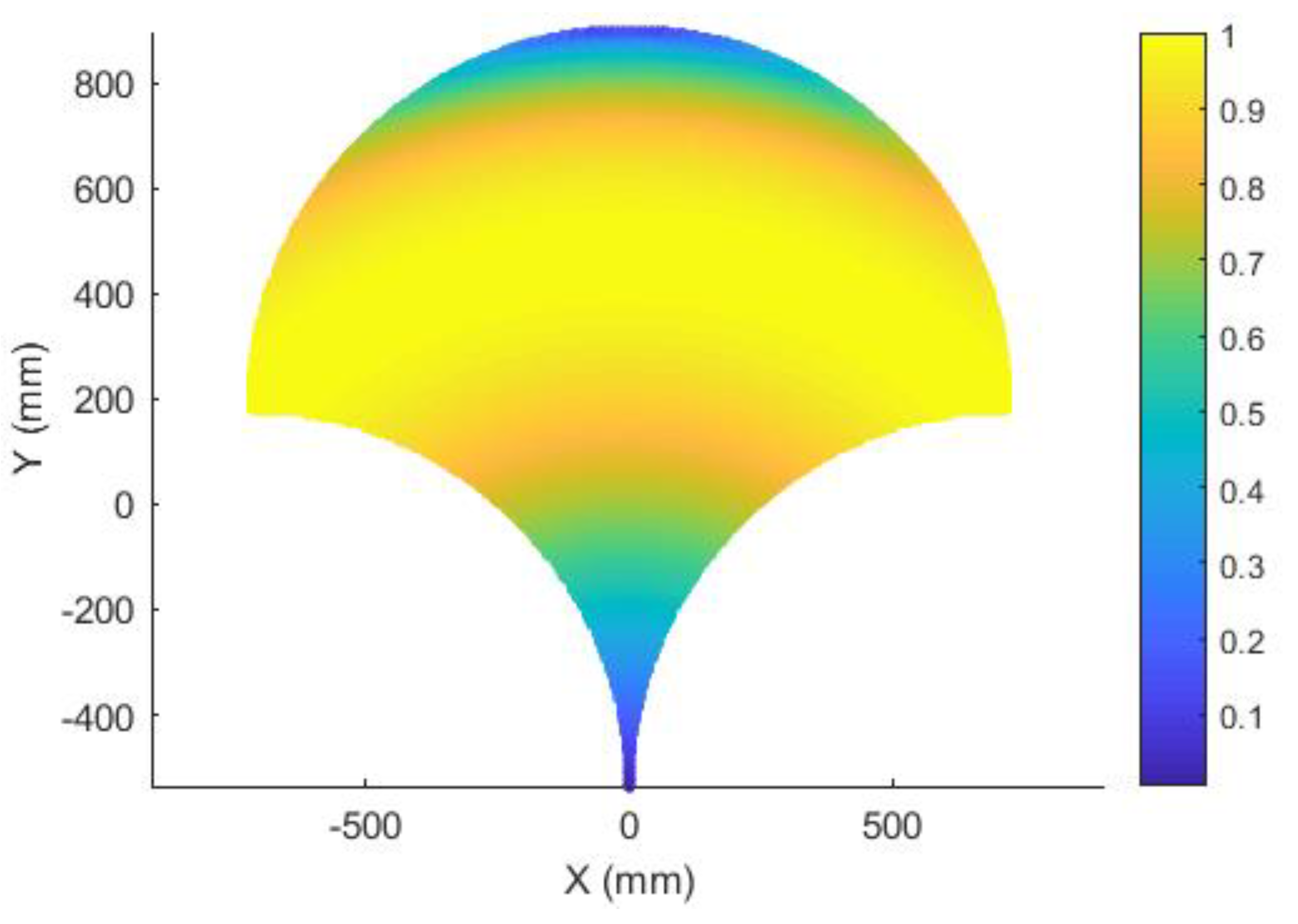
Figure 1a shows a scheme of the Nurse device and Figure 1b shows its workspace. The mechanism is composed by mobile links L1, L2, L3, L4, L6, L7, L8, L9 and fixed link L5. The point E, in Figure 1a, is a tracing point that is follow by the tracing point F with an amplification scale of 4. The mechanism has two active joints actuated by motors M1 and M2.
Nurse was numerically characterized in [25] and a lab prototype was experimentally characterized in [26]. In [25], the authors showed, through a dynamic analysis and an FEM analysis (finite element analysis), that Nurse is a feasible device for arm rehabilitation. In [26], the authors showed, through an experimental characterization, that Nurse is capable of reproducing different rehabilitation exercises. 
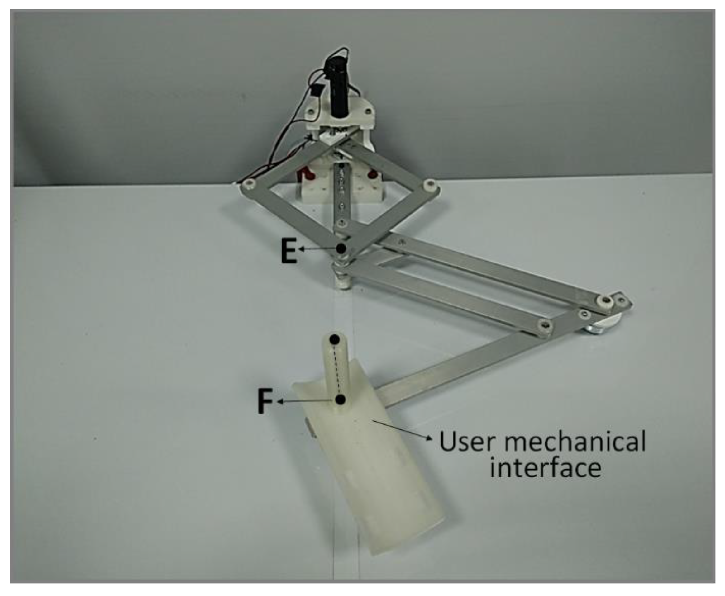
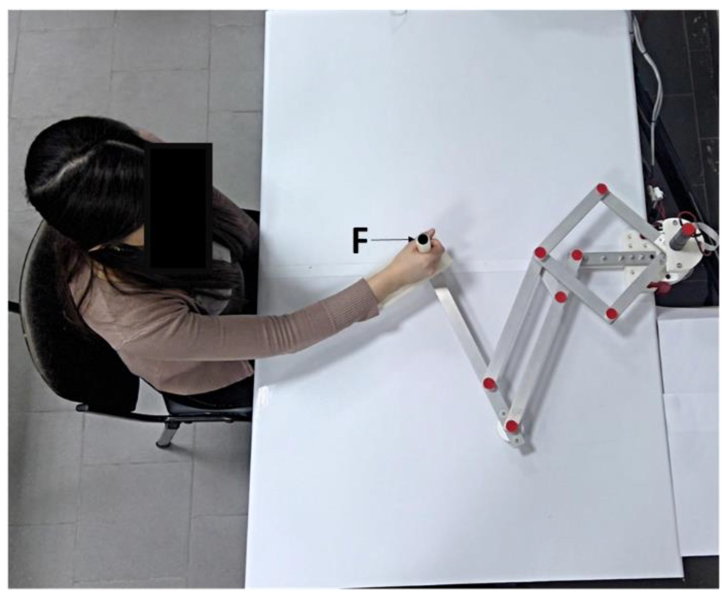
Figure 2 shows a lab prototype of Nurse and Figure 3 illustrates the user–mechanism interaction. The mechanism structure of Nurse weighs 2.6 kg and fits into a box of 35 × 45 × 30 cm when it is in a contracted position [25,26]. The planar mechanism linkage of Nurse is supported by two wheels that are placed under the tracing point E and the amplified tracing point F. The trajectory of the user mechanical interface is defined by the amplified tracing point 
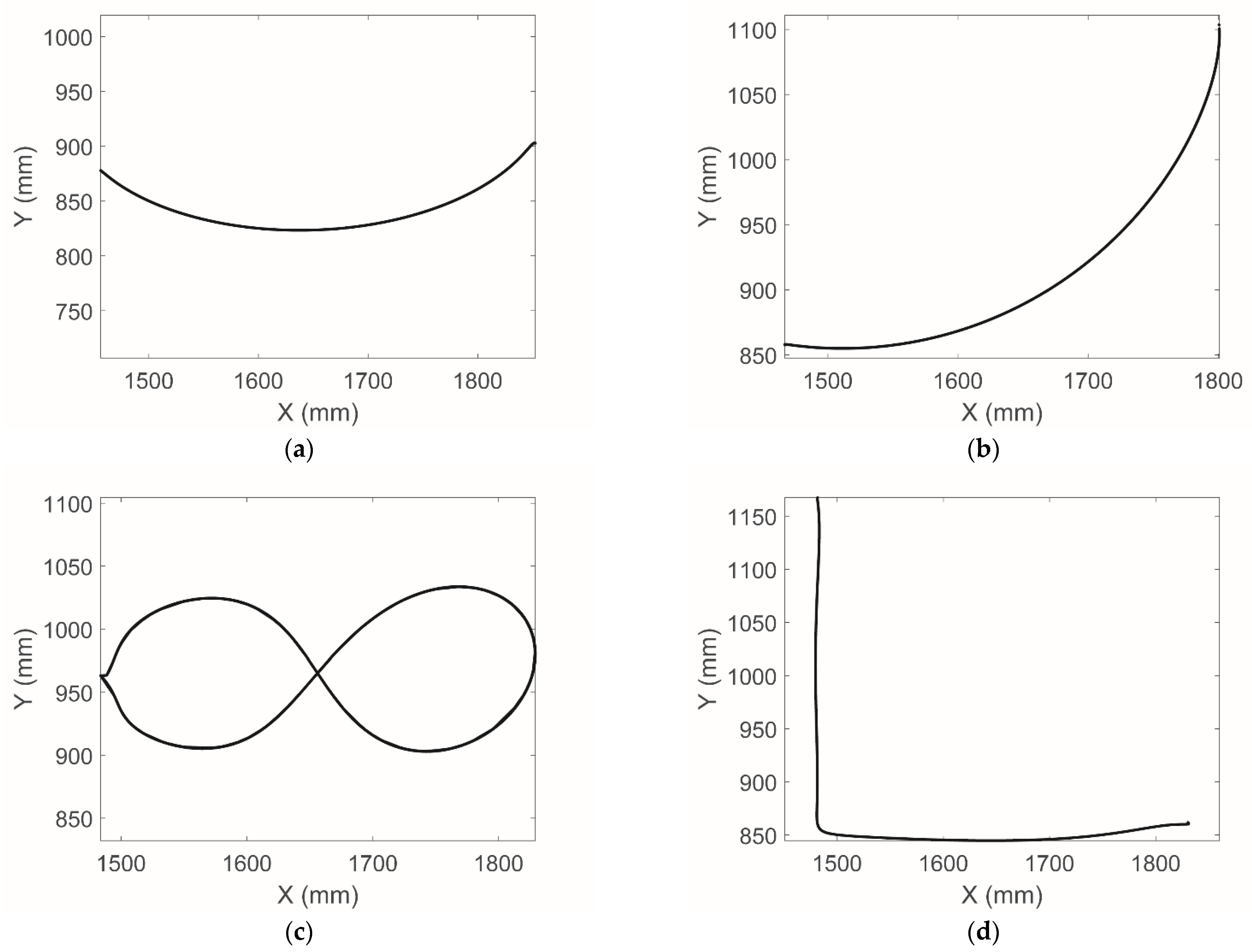
F. Nurse is capable of reproducing different trajectories for upper limb rehabilitation on a plane, including the trajectories for arm rehabilitation designed by the authors in [23], see Figure 4. Figure 4 shows four arm rehabilitation trajectories that were used for the experimental characterization of Nurse in [26]. In Figure 4, Trajectory 1 exercises the shoulder joint, Trajectory 2 the exercises the elbow joint, and Trajectory 3 and 4 exercise the elbow and shoulder joint at the same time. Although Nurse has several safety features, such as digital and physical emergency buttons, over current protections and the possibility of remembering the trajectories customized by the therapist for a particular patient, further safety analysis should be performed before experimenting with humans. Furthermore, a characterization of the workspace based on a transmission index is required for a better device performance.

2.2. Performance Analysis

To ensure safe and efficient use of the Nurse device, the torque of the actuators needs to be transmitted to the operator’s arm with a smooth and controlled behavior. While a safe behavior is intrinsic to mechanisms with compliant elements or driven by flexible tendons [28], rigid-link mechanisms such as Nurse require a careful motion planning and force transmission analysis [29]. Since the pantograph mechanism only amplifies the behavior of the actuated 5-bar linkage that generates the motion, the critical components for force transmission are links L1 and L4, as the two links that are directly actuated by the rotational motors, and L1 and L4, which transmit motion from the motors to path generating point E, as per Figure 1.
From a kinematic point of view, Nurse is characterized by two degrees of freedom actuated by two coaxial rotational motors (M1 and M2 in Figure 1), which directly define the motion of point E that is then amplified in point F by the pantograph. Thus, the architecture of the 5-bar linkage is characteristic of planar parallel mechanisms, with two independently actuated limbs (first limb: L1 to L2, second limb: L4 to L3) that converge in point E. As reported in [25], the motion of point E can be described as:
x E = H ( cos θ 1 + cos θ 2 )
y E = H ( sin θ 1 + sin θ 2 )
where the geometrical parameter H = L1 = L2 = L3 = L4 = L5 is fixed, and the angles θ 1 and θ 2 represent the actuation of M1 and M2, respectively. The position of point E can be defined by an angle α , as illustrated in Figure 5, which can be evaluated as:
α = t a n   1 ( y E H ) x E = t a n 1 ( y F H ) x F
and a distance r2, which can be computed from Equations (1) and (2) as:
r 2 = ( y E H ) 2 + x E 2
The forward kinematics of the full mechanism (up to point F) can be then obtained from the distance r1 from the amplification factor of the pantograph k as:
r 1 = k r 2 = L 9 L 8   r 2
The position of point F is thus given as:
x F = r 1 cos α = L 9 ( y E H ) 2 + x E 2 L 8 cos ( t a n 1 ( y E H ) x E )
y F = H + r 1 sin α = L 9 ( y E H ) 2 + x E 2 L 8 sin ( t a n 1 ( y E H ) x E )
This structure results in a non-linear relationship between the torques in the actuators and the force transmitted to point E (and, through that, to the extremity of the pantograph F). For this reason, an analysis of the performance of the 5-bar linkage is here proposed to characterize the transmission behavior of Nurse. The Transmission Index (TI) quantifies the relationship between the transmission wrench screw and the output twist screw, as explained by Chen and Angeles in [30]. The TI is widely recognized as one of the best indices to evaluate the static performance of parallel mechanisms [31] and to analyze their behavior in their reachable workspace [32], as singularities can be identified from discontinuities and null values for the TI. Some examples of applying the TI to parallel architectures are reported in [33,34,35]. In particular, the procedure developed in [34,
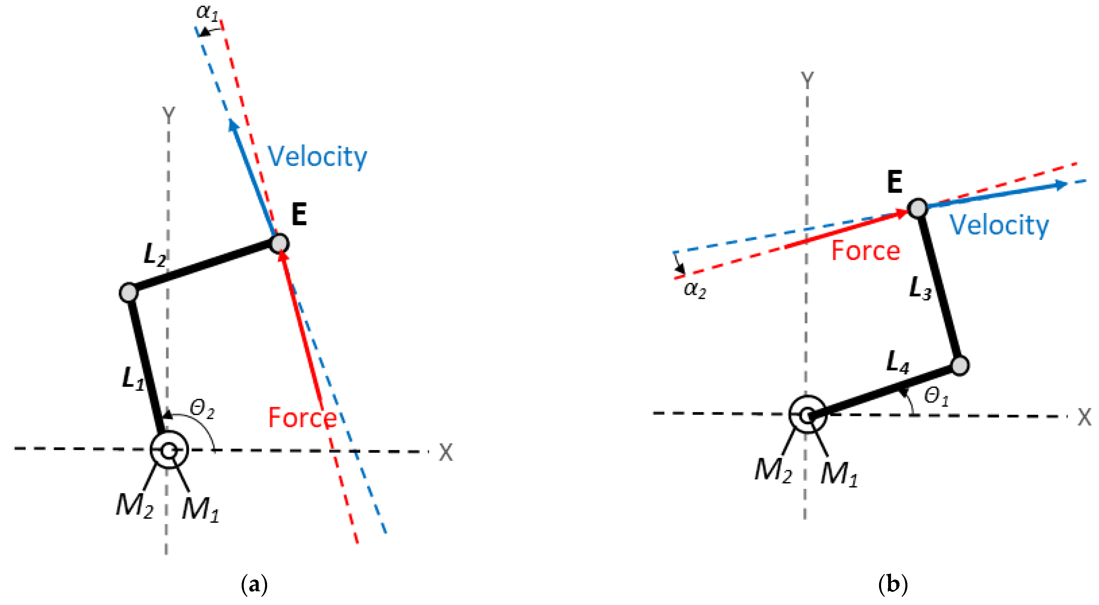
35] is adopted in this research to evaluate the TI, with reference to the kinematic scheme of the motion-generating 5-bar linkage of Nurse in Figure 6. This procedure requires the determination of a pressure angle α i , which is defined as the angle the direction of the force applied to a link and the resulting motion and can be evaluated for each degree of freedom of the mechanism with the following steps:
  • Locking the actuators of all the limbs of the parallel mechanism except for the one corresponding to the degree of freedom under analysis (limb i).
  • Substituting the non-locked actuator and its limb with the corresponding unit force transmitted to the end-effector.
  • Evaluating the instantaneous velocity corresponding to the motion of the end-effector resulting from the unit force applied in the previous point.
The pressure angle α i , relative to limb i and obtained as the angle between the force of point 2 and the velocity of point 3, can be used to obtain the force transmission efficiency η i in that limb as:
η i = cos α i
After evaluating η i for each limb, the output transmission index of the mechanism can be determined as:
T I = min ( η i )       i
In Nurse’s 5-bar linkage, the links L2 and L3 can only transmit forces along the link’s direction under the assumption of static balance with negligible friction and inertial effects. Thus, the direction of the unit force that these links can transmit to the end-effector is defined by the orientation of the link itself, which is θ 1 for link L2 (always parallel to input link L4) and θ 2 for link L3 (always parallel to input link L1).
When one of the parallel limbs of the 5-bar linkage is removed and the remaining actuator motion fixed, the only movable limb is L2 if removing the limb defined by L4 and L3, or L3 if removing the limb defined by L1 and L2. These movable limbs can only rotate around the revolute joints that connect them to their respective input links, resulting in an instantaneous velocity that is normal to the orientation of the link. Thus, the instantaneous velocity obtained when removing the limb defined by L4 and L3 is defined by an orientation of θ 1 + π / 2 , whereas the instantaneous velocity obtained when removing the limb defined by L1 and L2 is defined by an orientation of θ 2 + π / 2 .
Thus, the pressure angles corresponding to these two cases are:
α 1 = θ 2 θ 1 + π 2 ;   α 2 = θ 1 θ 2 + π 2 ;    
From Equation (10), the pressure angles are always equal in modulus (even if their sign can vary, depending on how they were defined). This means that the efficiency of the two limbs, defined as η i = cos α i as per Equation (8), is always the same due to the symmetry of the system. Therefore, the TI of the system in a given configuration can be computed as:
T I = cos ( θ 2 θ 1 + π 2 )

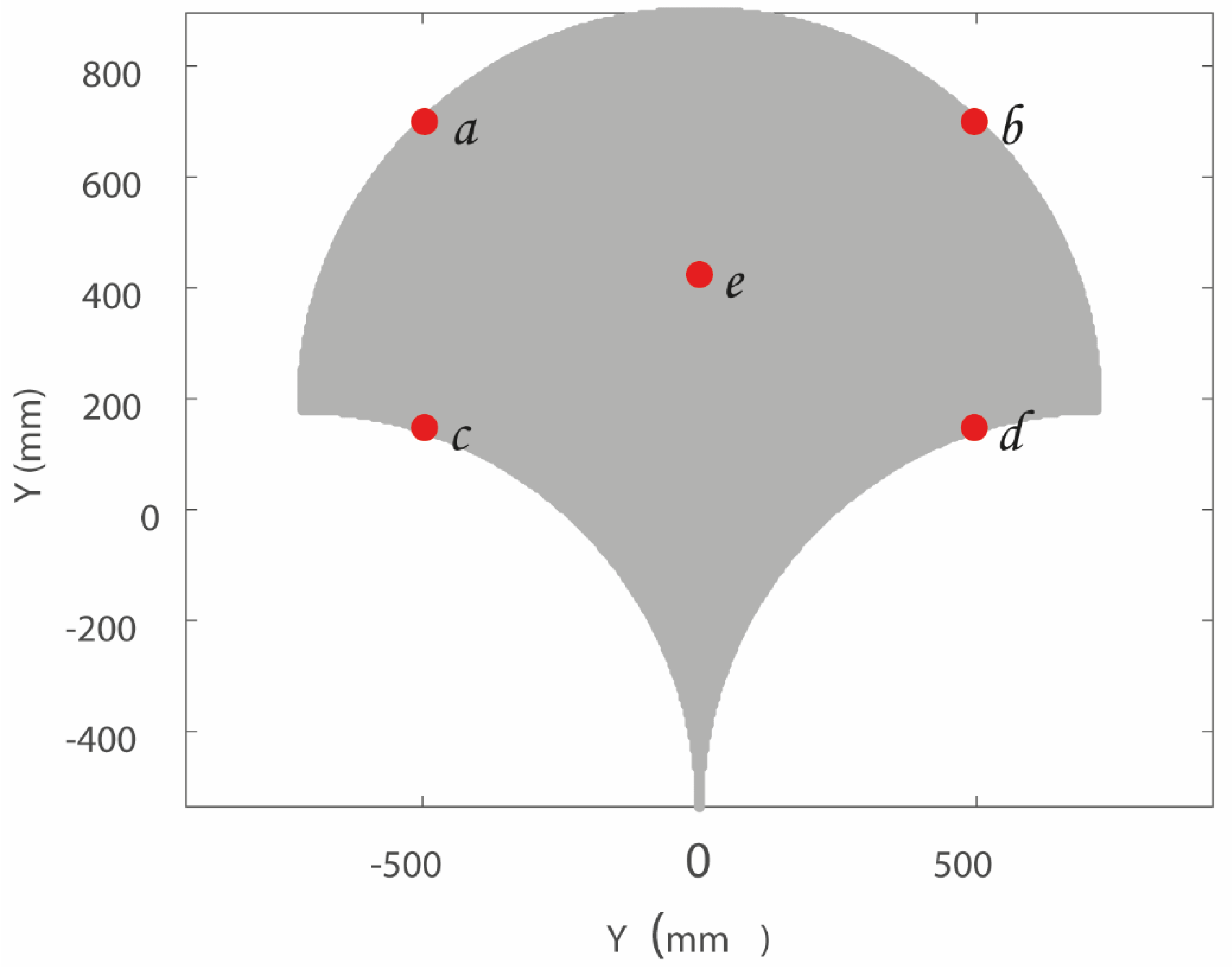
2.3. Operation Safety

A linear static FEM (finite element method) analysis has been performed in order to assess the produced stress on the human arm when Nurse device reaches critical positions within its workspace. Five critical positions within a mechanism workspace can be chosen by tracing an imaginary rectangle covering most of the workspace (Norm ISO 9283 [36]). The central point and the four corners of the imaginary rectangle are five critical positions. 
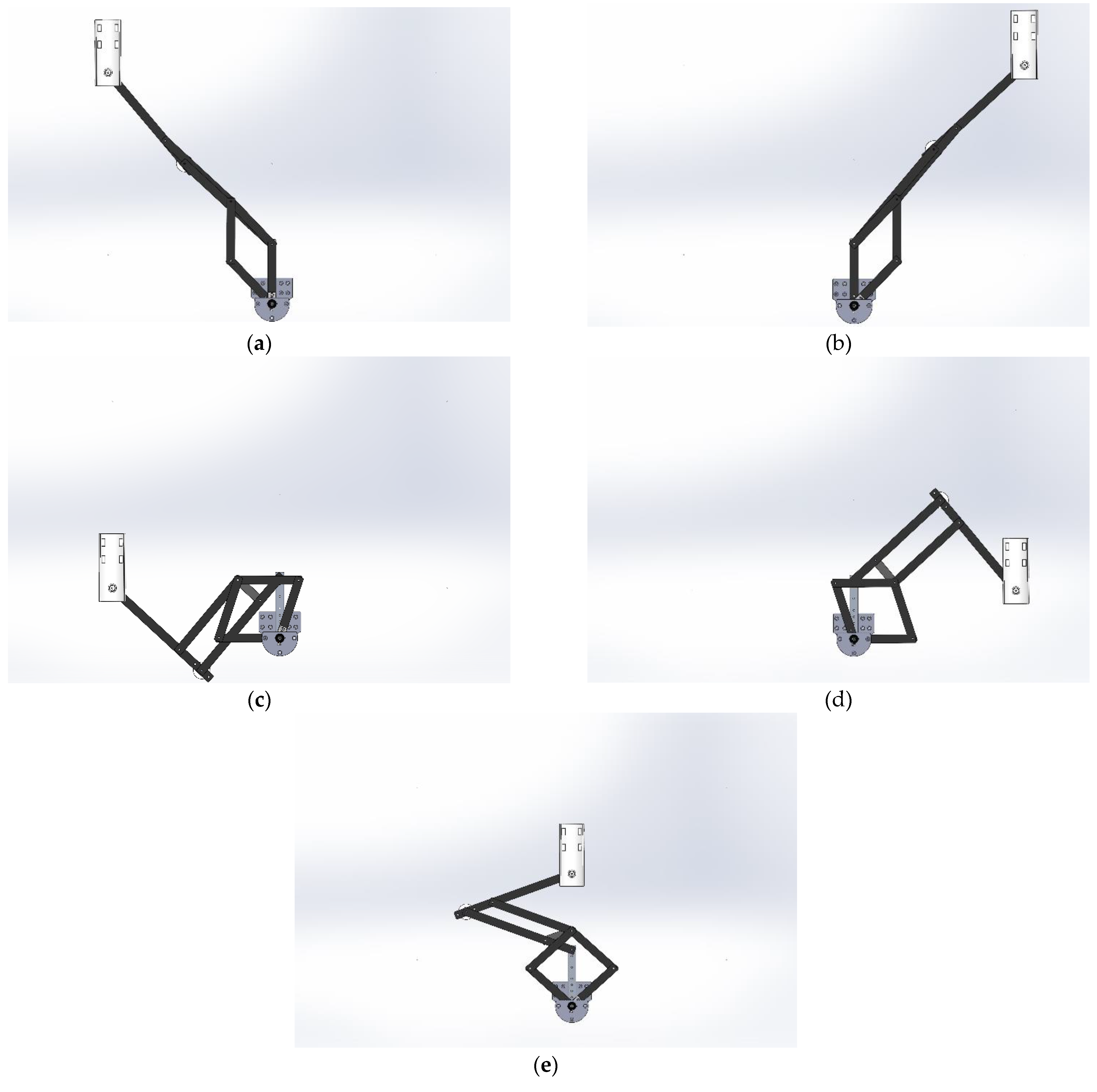
Figure 7 shows five critical positions within the Nurse workspace, where point a, point b, point c, and point d are the corners of the imaginary rectangle and point e is the central point of the rectangle. 
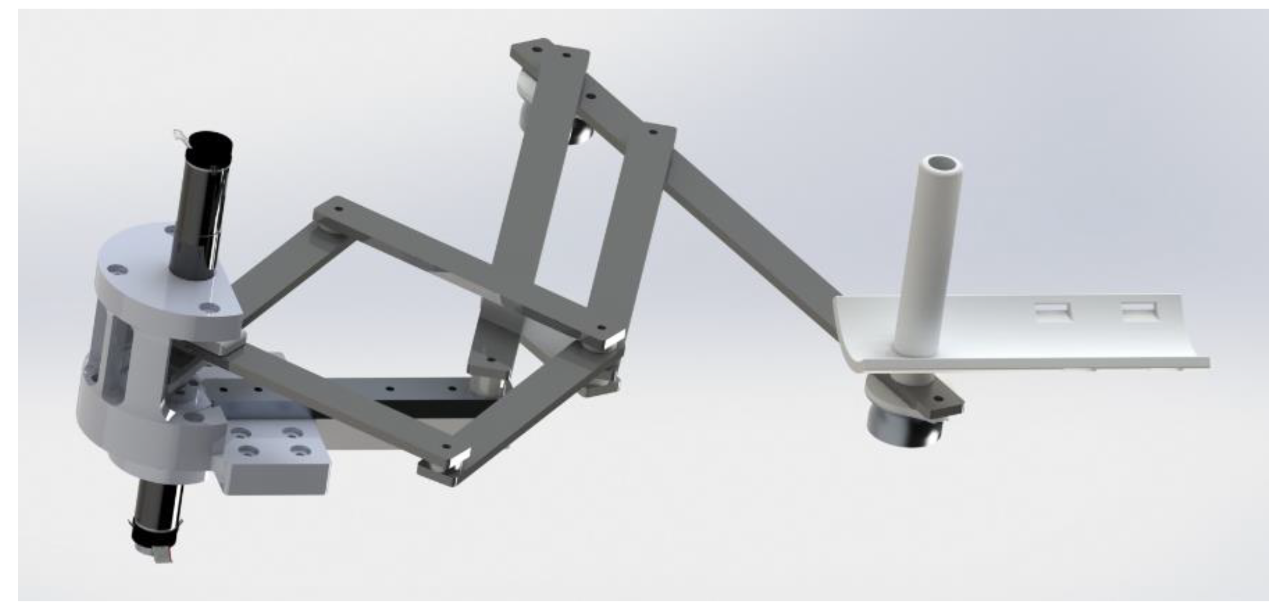
Figure 8 shows a CAD (computer-aided design) of the Nurse device that emulates the real lab prototype. 
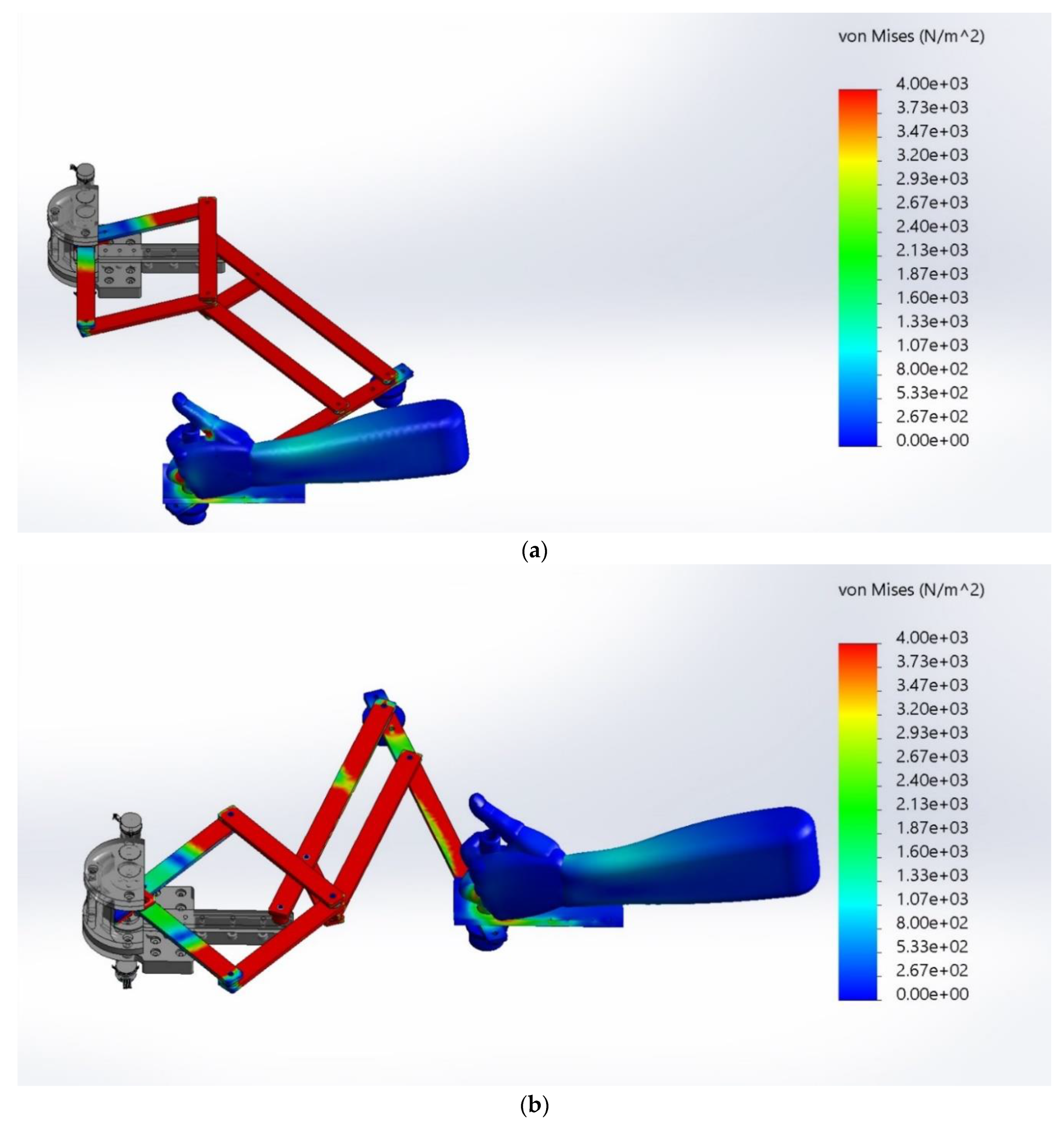
Figure 9a–e show the Nurse device on the positions a (−496, 700), b (496, 700), c (−496, 148), d (496, 148), e (0, 424), respectively.
During the simulation, a 1060 aluminum alloy has been used for Nurse bars and wheels and ABS (acrylonitrile butadiene styrene) has been used for the user mechanical interface. Table 1 shows the main material characteristics of the 1060 aluminum alloy and Table 2 shows the main characteristics of the ABS. It is important to note that the materials used during simulations correspond to the materials used in practice for the lab prototype of Nurse in Figure 2 and Figure 3.
Hyperelastic materials can be used to simulate the biological skeletal muscle behavior [37]. Particularly, silicone materials have the ability to imitate the distribution of stress in muscle tissue [
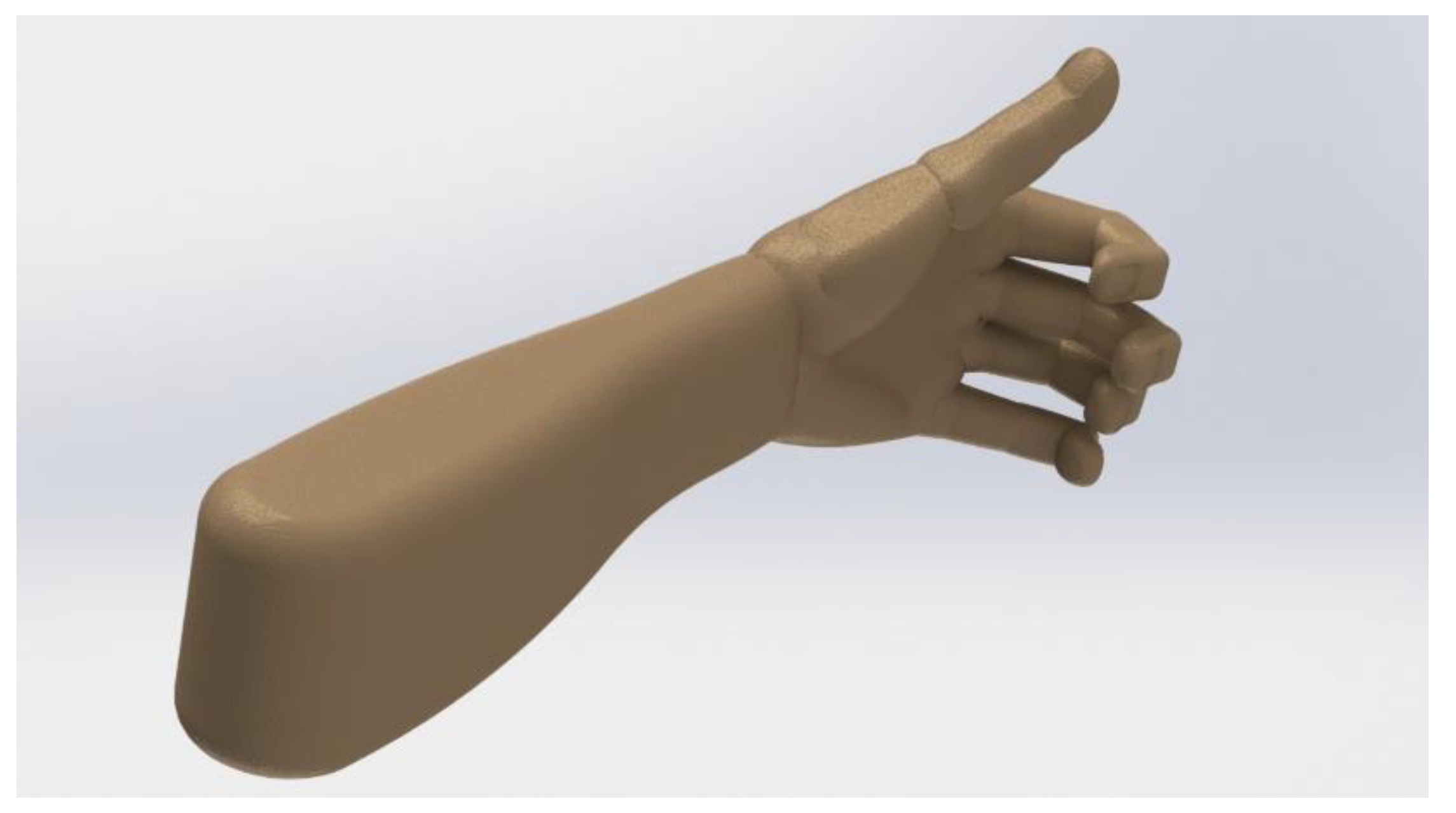
38]. Therefore, to carry out the FEM analysis, a human arm has been simulated using silicone. Table 3 shows the main material characteristics of the used silicone. The weight of the simulated human arm part (hand + forearm part) has been assumed as 1.18 Kg according to the average weight of a human arm [39,40]. Figure 10 shows the simulated human arm. The used CAD model of the human arm with articulated fingers is an open access model available online in [41].
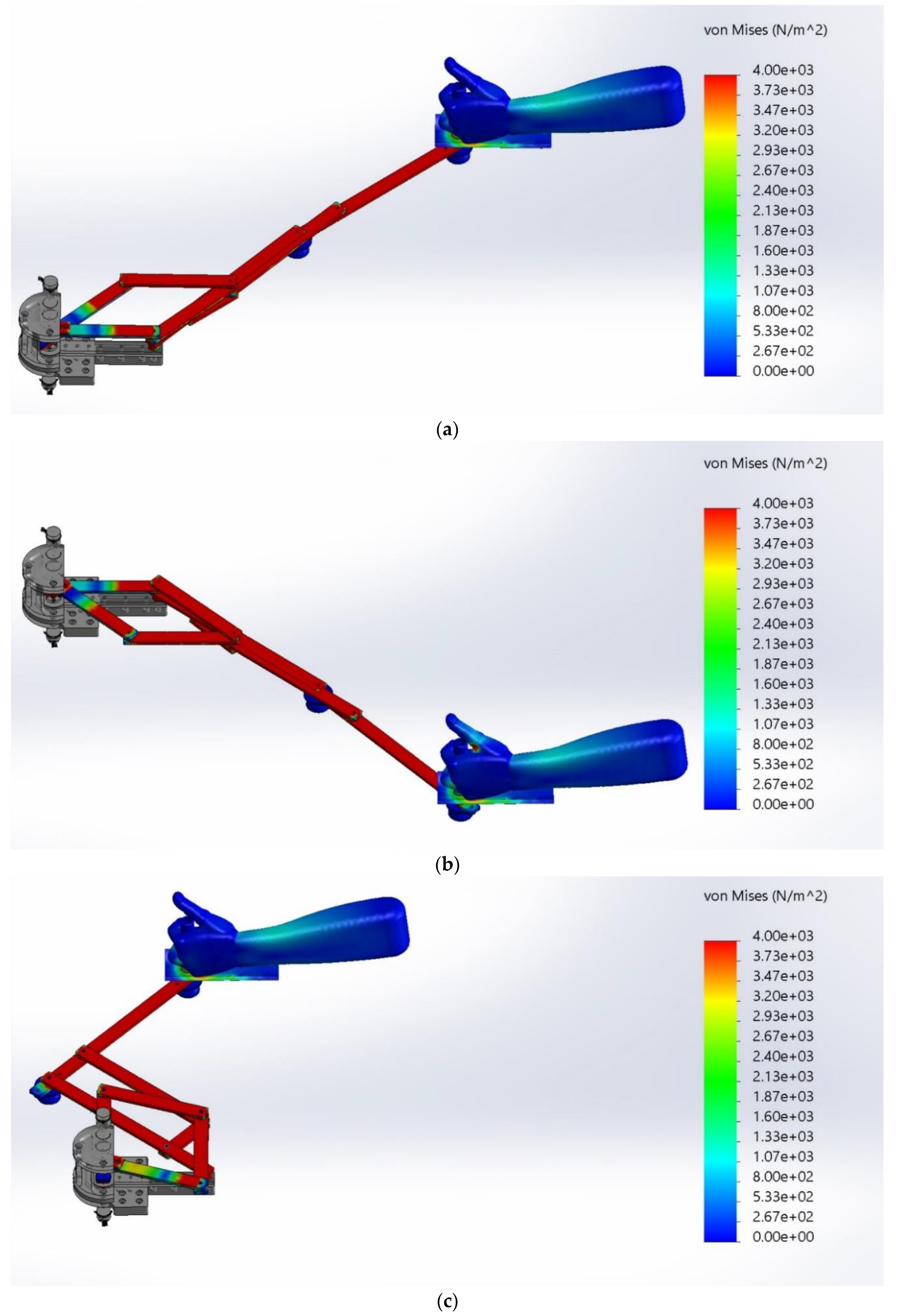
During the FEM simulation, gravity force acts along the Z axis. In addition, a torque of 3.53 Nm has been used for each motor of Nurse device (M1 and M2). The motor torque of 3.53 Nm is the maximum torque required by the motors of Nurse prototype during the reproduction of arm rehabilitation exercises according to the experimental tests published in [26].
Table 4 shows the main characteristics of the mesh used for the FEM analysis. The Von Mises stress function has been used to measure the three main stresses acting on X, Y, and Z axes of the human arm. The Von Mises stress function σvm is expressed as [42]:
σ V o n M i s e s = ( σ 1 σ 2 ) 2 + ( σ 2 σ 3 ) 2 + ( σ 3 σ 1 ) 2 2
where:
σ1 = principal stress acting on X.
σ2 = principal stress acting on Y.
σ3 = principal stress acting on Z.

3. Results and Discussion

3.1. Performance Analysis

By using the forward kinematics in Equations (6) and (7), the TI in Equation (11) can be mapped in the workspace of the Nurse device. In order to obtain operational parameter values, the design values defined in [25] are adopted for this evaluation, as summarized in Table 5. By using those values, Equation (11) was computed throughout the reachable workspace of Nurse, as shown by the colormap in Figure 11.
The workspace in Figure 11 does not represent the full amplified workspace of the 5-bar linkage illustrated in Figure 6, since its motion is physically constrained by the length of the pantograph’s links. Therefore, only a central region of the full workspace of the 5-bar linkage is actually reachable, and this reflects into the workspace in Figure 6. It is possible to observe that the central region of the workspace is characterized by a good performance, with optimal force transmission in those points that corresponds to a perfect square configuration of the 5-bar linkage (i.e., when θ 2 θ 1 = π / 2 ), with the TI reaching its maximum allowed value of 1. The two regions above and below these optimal values, which all lie in an arc of circumference, are characterized by values that become gradually smaller the more they are distant from the optimal region.
The central region of the workspace is characterized by a TI value of 0.8 and covers more than 75% of the reachable workspace. In the remaining regions, at the top and the bottom of the workspace in Figure 11, the TI slowly decreases to a minimum value of 0.0056. While this represents a point of extremely low efficiency, it is important to note that the TI never reaches a value of zero. Since the TI of a mechanism becomes zero in singular configurations, this means that the physical constraints to the motion of the 5-bar linkage imposed by the pantograph not only have the effect of reducing its motion range, but also prevent it from reaching any singular configuration (a desirable outcome).
Overall, this result demonstrates that the proposed design performs well from a force transmission point of view, avoiding any singular configurations that might cause a control failure and subsequent risk for the user, and supporting the user’s motion with a good efficiency throughout its operational workspace.

3.2. Operation Safety

Human arm stresses have been obtained from the FEM analysis. Figure 12 shows the stress values on the human arm when Nurse reaches the critical positions a (−496),700, b (496,700) and c (−496,148). Figure 13 shows the stress values on the human arm when Nurse reaches the critical positions d (496,148) and e (0,424). Table 6 shows the maximum stress values on the human arm when Nurse reaches the five critical positions.
Skeletal muscles have a complex nature, and some mechanical properties cannot be estimated in a noninvasive way [43]. Therefore, these quantities are estimated using mathematical models [43]. According to the main mechanical models of skeletal muscles [43,44,45,46], a muscle has a maximum peak stress of 668.80 × 10³ N/m2 [44,45,46], a maximal contractile stress of 30 × 103 N/m2 [47], and a maximum isometric stress of 300 × 103 N/m2 [48,49]. The FEM analysis results, in Figure 12 and Figure 13, and Table 6, show that the human arm achieves a maximum stress value when the Nurse device reaches the critical position d (496,148) with a maximum stress of 6.55 × 10³ N/m2. Therefore, stress values on the human arm when Nurse reaches critical positions are negligible with respect to the mentioned mechanical properties of the skeletal muscles. On the other hand, the achieved stress values are negligible with respect to the average bending strength (the material’s ability to withstand stress) of the humerus (128,430 × 103 N/m2), ulna (135,160 × 103 N/m2), and radius (80,310 × 103 N/m2) [50]. In summary, the stress results show that the Nurse operation is safe for the human arm.

4. Conclusions

In this paper, an assistive device for the upper limb, called Nurse, is presented and characterized with numerical simulations. The proposed mechanism is made of a five-bar linkage that is actuated by two motors and generates a trajectory for a user’s arm. The motion of the five-bar linkage is amplified by a pantograph to obtain a wide workspace that covers a typical human arm’s mobility while maintaining a good force transmission efficiency, as shown by the transmissibility analysis in this manuscript. Furthermore, operation safety is demonstrated with a finite element analysis in five critical positions for the proposed assistive device: four at the borders of its operational workspace, and one at its center. The results of both the finite element analysis and the Transmission Index evaluation validate the feasibility of using the Nurse design and prove both its efficiency and safety in assisting and guiding exercises for arm rehabilitation.

5. Patents

Chaparro-Rico, B. D. M.; Cafolla, D.; Ceccarelli, M.; Castillo-Castaneda, E. Device for arm motion assistance, Italian Patent No. 102016000107499, granted on 12 March 2019.

Author Contributions

Conceptualization, M.C., M.R., D.C. and B.D.M.C.-R.; methodology, M.R., D.C. and B.D.M.C.-R.; validation, M.R., D.C. and B.D.M.C.-R.; formal analysis, M.R., D.C. and B.D.M.C.-R.; investigation, M.R., D.C. and B.D.M.C.-R.; resources, M.C., M.R., D.C. and B.D.M.C.-R.; data curation, M.R., D.C. and B.D.M.C.-R.; writing—original draft preparation, M.R. and B.D.M.C.-R.; writing—review and editing, M.R., D.C. and B.D.M.C.-R.; visualization, M.R., D.C. and B.D.M.C.-R.; supervision, B.D.M.C.-R.; project administration, B.D.M.C.-R.; funding acquisition, M.C., M.R., D.C. and B.D.M.C.-R. All authors have read and agreed to the published version of the manuscript.

Funding

This research received no external funding.

Conflicts of Interest

The authors declare no conflict of interest.

References

  1. Burgar, C.G.; Lum, P.S.; Shor, P.C.; Van der Loos, H.M. Development of robots for rehabilitation therapy: The Palo Alto VA/Stanford experience. J. Rehabil. Res. Dev. 2000, 37, 663–673. [Google Scholar]
  2. Lum, P.S.; Burgar, C.G.; Shor, P.C.; Majmundar, M.; Van der Loos, M. Robot-assisted movement training compared with conventional therapy techniques for the rehabilitation of upper-limb motor function after stroke. Arch. Phys. Med. Rehabil. 2002, 83, 952–959. [Google Scholar] [CrossRef] [Green Version]
  3. Chu, C.Y.; Patterson, R.M. Soft robotic devices for hand rehabilitation and assistance: A narrative review. J Neuroeng. Rehabil. 2018, 15, 1–14. [Google Scholar] [CrossRef] [Green Version]
  4. Hesse, S.; Schmidt, H.; Werner, C.; Bardeleben, A. Upper and lower extremity robotic devices for rehabilitation and for studying motor control. Curr. Opin. Neurol. 2003, 16, 705–710. [Google Scholar] [CrossRef]
  5. Laurentis, K.J.; Won, J.; Alam, M.; Mavroidis, C. Fabrication of Non-Assembly Mechanisms and Robotic Systems Using Rapid Prototyping. ASME. J. Mech. Des. 2001, 123, 516–524. [Google Scholar] [CrossRef]
  6. Nematollahi, M.; Baghbaderani, K.S.; Amerinatanzi, A.; Zamanian, H.; Elahinia, M. Application of NiTi in Assistive and Rehabilitation Devices: A Review. Bioengineering 2019, 6, 37. [Google Scholar] [CrossRef] [Green Version]
  7. Riener, R.; Nef, T.; Colombo, G. Robot-aided Neurorehabilitation of the Upper Extremities. Med. Biol. Eng. Comput. 2005, 43, 2–10. [Google Scholar] [CrossRef] [PubMed] [Green Version]
  8. Gull, M.A.; Bai, S.; Bak, T. A Review on Design of Upper Limb Exoskeletons. Robotics 2020, 9, 16. [Google Scholar] [CrossRef] [Green Version]
  9. Ball, S.J.; Brown, I.E.; Scott, S.H. A Planar 3dof Robotic Exoskeleton for Rehabilitation and Assessment. In Proceedings of the 29th Annual Conference of the IEEE EMBS Cité Internationale, Lyon, France, 23–26 August 2007; IEEE: Paris, France, 2007; pp. 4024–4027. [Google Scholar] [CrossRef]
  10. Maciejasz, P.; Eschweiler, J.; Gerlach-Hahn, K.; Jansen-Troy, A.; Leonhardt, S. A survey on robotic devices for upper limb rehabilitation. J. Neuroeng. Rehabil. 2014, 11, 3. [Google Scholar] [CrossRef] [Green Version]
  11. Nef, T.; Guidali, M.; Riener, R. ARMin III–Arm Therapy Exoskeleton with an Ergonomic Shoulder Actuation. Appl. Bionics Biomech. 2009, 6, 127–142. [Google Scholar] [CrossRef] [Green Version]
  12. de la Tejera, J.A.; Bustamante-Bello, R.; Ramirez-Mendoza, R.A.; Izquierdo-Reyes, J. Systematic Review of Exoskeletons towards a General Categorization Model Proposal. Appl. Sci. 2021, 11, 76. [Google Scholar] [CrossRef]
  13. Mao, Y.; Agrawal, S.K. Design of a Cable-Driven Arm Exoskeleton (CAREX) for Neural Rehabilitation. IEEE Trans. Robot. 2012, 28, 922–931. [Google Scholar] [CrossRef]
  14. Brokaw, E.B.; Murray, T.; Nef, T.; Lum, P.S. Retraining of interjoint arm coordination after stroke using robot-assisted time-independent functional training. J. Rehabil. Res. Dev. 2011, 48, 299–316. [Google Scholar] [CrossRef] [PubMed]
  15. Binns, M.; Protas, E.D.; Avenarius, S. Shoulder Rehabilitation and Exercise Device. U.S. Patent No. US008251879B2, 28 August 2012. [Google Scholar]
  16. Campolo, D.; Widjaja, F.; Klein Hubert, J. An Apparatus for Upper Body Movement. U.S. Patent Application 2015/0302777 A1, 22 October 2016. [Google Scholar]
  17. Annisa, J.; Mohamaddan, S.; Jamaluddin, M.S.; Aliah, A.N.; Omar, A.; Helmy, H.; Norafizah, A. Development of Upper Limb Rehabilitation Robot Prototype for Home Setting. In Proceedings of the 5th Brunei International Conference on Engineering and Technology (BICET 2014), Bandar Seri Begawan, Brunei, 1–3 November 2014; IET: Bandar Seri Begawan, Brunei, 2014; pp. 1–6. [Google Scholar] [CrossRef]
  18. Krebs, H.I.; Ferraro, M.; Buerger, S.P.; Newbery, M.J.; Makiyama, A.; Sandmann, M.; Lynch, D.; Volpe, B.T.; Hogan, N. Rehabilitation robotics: Pilot trial of a spatial extension for MIT-Manus. J. NeuroEng. Rehabil. 2004, 1, 5. [Google Scholar] [CrossRef] [PubMed] [Green Version]
  19. Qassim, H.M.; Wan Hasan, W.Z. A Review on Upper Limb Rehabilitation Robots. Appl. Sci. 2020, 10, 6976. [Google Scholar] [CrossRef]
  20. Rodríguez-León, J.F.; Chaparro-Rico, B.D.M.; Russo, M.; Cafolla, D. An Autotuning Cable-Driven Device for Home Rehabilitation. J. Healthc. Eng. 2021, 2021, 6680762. [Google Scholar] [CrossRef] [PubMed]
  21. Cafolla, D.; Russo, M.; Carbone, G. Design of CUBE, a Cable-Driven Device for Upper and Lower Limb Exercising. In New Trends in Medical and Service Robotics. Mechanisms and Machine Science; Carbone, G., Ceccarelli, M., Pisla, D., Eds.; Springer: Cham, Switzerland, 2019; Volume 65, pp. 255–263. [Google Scholar] [CrossRef]
  22. Xiong, H.; Diao, X. A review of cable-driven rehabilitation devices. Disabil. Rehabil. Assist. Technol. 2020, 15, 885–897. [Google Scholar] [CrossRef]
  23. Chaparro-Rico, B.D.M.; Cafolla, D.; Castillo-Castaneda, E.; Ceccarelli, M. Design of arm exercises for rehabilitation assistance. J. Eng. Res. 2020, 8, 204–218. [Google Scholar] [CrossRef]
  24. Chaparro-Rico, B.D.M.; Cafolla, D.; Ceccarelli, M.; Castillo-Castaneda, E. Design and Simulation of an Assisting Mechanism for Arm Exercises. In Advances in Italian Mechanism Science. Mechanisms and Machine Science; Boschetti, G., Gasparetto, A., Eds.; Springer: Cham, Switzerland, 2017; Volume 47, pp. 115–123. [Google Scholar] [CrossRef]
  25. Chaparro-Rico, B.D.M.; Cafolla, D.; Ceccarelli, M.; Castillo-Castaneda, E. NURSE-2 DoF Device for Arm Motion Guidance: Kinematic, Dynamic, and FEM Analysis. Appl. Sci. 2020, 10, 2139. [Google Scholar] [CrossRef] [Green Version]
  26. Chaparro-Rico, B.D.; Cafolla, D.; Ceccarelli, M.; Castillo-Castaneda, E. Experimental Characterization of NURSE, a Device for Arm Motion Guidance. J. Healthc. Eng. 2018, 2018, 9303282. [Google Scholar] [CrossRef] [Green Version]
  27. Bessler, J.; Prange-Lasonder, G.B.; Schaake, L.; Saenz, J.F.; Bidard, C.; Fassi, I.; Valori, M.; Lassen, A.B.; Buurke, J.H. Safety Assessment of Rehabilitation Robots: A Review Identifying Safety Skills and Current Knowledge Gaps. Front. Robot. AI 2021, 8, 602878. [Google Scholar] [CrossRef]
  28. Cafolla, D.; Russo, M.; Carbone, G. Design and validation of an inherently-safe cable-driven assisting device. Int. J. Mech. Control. 2018, 19, 23–32. [Google Scholar]
  29. Carbone, G.; Gerding, E.C.; Corves, B.; Cafolla, D.; Russo, M.; Ceccarelli, M. Design of a Two-DOFs driving mechanism for a motion-assisted finger exoskeleton. Appl. Sci. 2020, 10, 2619. [Google Scholar] [CrossRef] [Green Version]
  30. Chen, C.; Angeles, J. Generalized transmission index and transmission quality for spatial linkages. Mech. Mach. Theory 2007, 42, 1225–1237. [Google Scholar] [CrossRef]
  31. Xie, F.; Liu, X.J.; Wang, J. Performance evaluation of redundant parallel manipulators assimilating motion/force transmissibility. Int. J. Adv. Robot. Syst. 2011, 8, 113–124. [Google Scholar] [CrossRef]
  32. Wang, J.; Wu, C.; Liu, X.J. Performance evaluation of parallel manipulators: Motion/force transmissibility and its index. Mech. Mach. Theory 2010, 45, 1462–1476. [Google Scholar] [CrossRef]
  33. Liu, H.; Huang, T.; Kecskeméthy, A.; Chetwynd, D.G. A generalized approach for computing the transmission index of parallel mechanisms. Mech. Mach. Theory 2014, 74, 245–256. [Google Scholar] [CrossRef] [Green Version]
  34. Liang, X.; Takeda, Y. Transmission index of a class of parallel manipulators with 3-RS (SR) primary structures based on pressure angle and equivalent mechanism with 2-SS chains replacing RS chain. Mech. Mach. Theory 2019, 139, 359–378. [Google Scholar] [CrossRef]
  35. Russo, M.; Ceccarelli, M.; Takeda, Y. Force transmission and constraint analysis of a 3-SPR parallel manipulator. Proc. Inst. Mech. Eng. Part C J. Mech. Eng. Sci. 2018, 232, 4399–4409. [Google Scholar] [CrossRef]
  36. ISO International Organization for Standardization. ISO 9283:1998. Available online: https://www.iso.org/standard/22244.html (accessed on 21 October 2021).
  37. Ansari, M.Z.; Lee, S.K.; Cho, C.D. Hyperelastic Muscle Simulation. KEM 2007, 345–346, 1241–1244. [Google Scholar] [CrossRef]
  38. Sparks, J.L.; Vavalle, N.A.; Kasting, K.E.; Long, B.; Tanaka, M.L.; Sanger, P.A.; Schnell, K.; Conner-Kerr, T.A. Use of silicone materials to simulate tissue biomechanics as related to deep tissue injury. Adv. Skin Wound Care 2015, 28, 59–68. [Google Scholar] [CrossRef] [PubMed]
  39. Pineau, J.C.; Delamarche, P.; Bozinovic, S. Average Height of Adolescents in the Dinaric Alps. C. R. Biol. 2005, 328, 841–846. [Google Scholar] [CrossRef]
  40. Hall, S.J. Basic Biomechanics, 6th ed.; McGraw Hill: New York, NY, USA, 2012; p. 538. [Google Scholar]
  41. Schmit, J. Human Left Hand. Available online: https://grabcad.com/library/human-left-hand (accessed on 18 October 2021).
  42. Budynas, R.G.; Nisbett, J.K.; Shigley, J.E. Shigley’s Mechanical Engineering Design, 8th ed.; McGraw-Hill: New York, NY, USA, 2008; p. 216. [Google Scholar]
  43. Dao, T.T.; Tho, M.-C.H.B. A Systematic Review of Continuum Modeling of Skeletal Muscles: Current Trends, Limitations, and Recommendations. Appl. Bionics. Biomech. 2018, 2018, 7631818. [Google Scholar] [CrossRef] [PubMed]
  44. Martins, J.A.C.; Pires, E.B.; Salvado, R.; Dinis, P.B. A numerical model of passive and active behavior of skeletal muscles. Comput. Methods Appl. Mech. Eng. 1998, 151, 419–433. [Google Scholar] [CrossRef]
  45. Toumanidou, T.; Noailly, J. Musculoskeletal modeling of the lumbar spine to explore functional interactions between back muscle loads and intervertebral disk Multiphysics. Front. Bioeng. Biotechnol. 2015, 3, 11. [Google Scholar] [CrossRef] [Green Version]
  46. Fan, A.X.; Dakpé, S.; Dao, T.T.; Pouletaut, P.; Rachik, M.; Ho Ba Tho, M.C. MRI-based finite element modeling of facial mimics: A case study on the paired zygomaticus major muscles. Comput. Methods Biomech. Biomed. Eng. 2017, 20, 919–928. [Google Scholar] [CrossRef]
  47. Röhrle, O. Simulating the electro-mechanical behavior of skeletal muscles. Comput. Sci. Eng. 2010, 12, 48–58. [Google Scholar] [CrossRef]
  48. Tang, C.Y.; Tsui, C.P.; Stojanovic, B.; Kojic, M. Finite element modelling of skeletal muscles coupled with fatigue. Int. J. Mech. Sci. 2007, 49, 1179–1191. [Google Scholar] [CrossRef]
  49. Blemker, S.S.; Pinsky, P.M.; Delp, S.L. A 3D model of muscle reveals the causes of nonuniform strains in the biceps brachii. J. Biomech. 2005, 38, 657–665. [Google Scholar] [CrossRef]
  50. Singh, D.; Rana, A.; Jhajhria, S.K.; Garg, B.; Pandey, P.M.; Kalyanasundaram, D. Experimental assessment of biomechanical properties in human male elbow bone subjected to bending and compression loads. J. Appl. Biomater. Funct. 2019, 17, 1–13. [Google Scholar] [CrossRef]
Figure 1. Nurse device: (a) scheme of the linkage structure; (b) mechanism workspace.
Inventions 06 00085 g001
Figure 2. A lab prototype of Nurse device.
Inventions 06 00085 g002
Figure 3. User–mechanism interaction.
Inventions 06 00085 g003
Figure 4. Trajectories for upper limb rehabilitation: (a) Trajectory 1; (b) Trajectory 2; (c) Trajectory 3; (d) Trajectory 4.
Inventions 06 00085 g004
Figure 5. Kinematic diagram of Nurse with motion and design parameters [25].
Inventions 06 00085 g005
Figure 6. Kinematic diagram of the 5-bar linkage of Nurse with main twist and wrench directions: (a) pressure angle of the first limb in an example configuration; (b) pressure angle of the second limb in an example configuration.
Inventions 06 00085 g006
Figure 7. Five critical positions (a (−496, 700), b (496, 700), c (−496, 148), d (496, 148), e (0, 424)) within the NURSE workspace.
Inventions 06 00085 g007
Figure 8. A CAD (computer-aided design) of Nurse device.
Inventions 06 00085 g008
Figure 9. Nurse device on critical positions: (a) critical position a (−496, 700); (b) critical position b (496, 700); (c) critical position c (−496, 148); (d) critical position d (496, 148); (e) critical position e (0, 424).
Inventions 06 00085 g009
Figure 10. Simulated human arm.
Inventions 06 00085 g010
Figure 11. Transmission Index distribution in the workspace.
Inventions 06 00085 g011
Figure 12. Stress results when Nurse reaches critical positions: (a) critical position a (−496,700); (b) critical position b (496,700); (c) critical position c (−496,148).
Inventions 06 00085 g012
Figure 13. Stress results when Nurse reaches critical positions: (a) critical position d (496, 148); (b) critical position e (0, 424).
Inventions 06 00085 g013
Table 1. Main characteristics of 1060 aluminum alloy.
PropertiesUnits1060 Aluminum
Elastic ModulusN/m26.90 × 1010
Poisson’s RatioN/A0.33
Shear ModulusN/m22.70 × 1010
Mass Densitykg/m32 700
Tensile StrengthN/m26.89 × 107
Yield StrengthN/m22.76 × 107
Table 2. Material characteristics of the ABS (Acrylonitrile Butadiene Styrene) material.
PropertiesUnitsABS 1
Elastic ModulusN/m20.2 × 1010
Poisson’s RatioN/A0.39
Shear ModulusN/m20.32 × 1010
Mass Densitykg/m31020
Tensile StrengthN/m23 × 107
1 ABS (acrylonitrile butadiene styrene).
Table 3. Material characteristics of the used silicone material.
PropertiesUnitsSilicone
Elastic ModulusN/m211.24 × 1010
Poisson’s RatioN/A0.28
Shear ModulusN/m24.9 × 1010
Mass Densitykg/m32330
Yield StrengthN/m212 × 107
Table 4. Mesh information for FEM (finite element method) analysis.
Mesh TypeSolid Mesh
Mesh typeMixed Mesh
Mesher UsedCurvature-based mesh
Jacobian points16 Points
Maximum element size15.40 mm
Minimum element size3.08 mm
Total Nodes264,679
Total Elements157,419
Table 5. Design parameters of the Nurse prototype.
VariableValueUnits
L1180mm
L2180mm
L3180mm
L4180mm
L5180mm
L6360mm
L7270mm
L890mm
L9360mm
Table 6. Maximum stress values on the human arm when Nurse reaches five critical positions.
Critical PositionsMaximum Stress Values
a (−496, 700)3.99 × 10³ N/m2
b (496, 700)4.41 × 10³ N/m2
c (−496, 148)6.53 × 10³ N/m2
d (496, 148)6.55 × 10³ N/m2
e (0, 424)4.43 × 10³ N/m2
Publisher’s Note: MDPI stays neutral with regard to jurisdictional claims in published maps and institutional affiliations.

