Review

Advanced Power Generation Using a Nitrogen Turbine Engine Instead of a Conventional Injection Steam Turbine Engine

by
Wenich Vattanapuripakorn
1,
Khomson Khannam
1,
Sathapon Sonsupap
1,
Prachakon Kaewkhiaw
2,
Umakorn Tongsantia
3,
Jiradanai Sarasamkan
4 and
Bopit Bubphachot
5,*
1
Department of Mechanical Engineering, Faculty of Engineering, Mahasarakam University, Mahasarakam 44150, Thailand
2
Department of Maritime Engineering, Faculty of International Maritime Studies, Kasetsart University Sriracha Campus, Chon Buri 20230, Thailand
3
Department of Public Health Administration, Faculty of Public Health, Khon Kaen University, Khon Kaen 40002, Thailand
4
Department of Radiology, Faculty of Medicine, Khon Kaen University, Khon Kaen 40002, Thailand
5
Heat Pipe and Thermal Tools Design Research Unit (HTDR), Faculty of Engineering, Mahasarakam University, Mahasarakam 44150, Thailand
*
Author to whom correspondence should be addressed.
Inventions 2021, 6(4), 62; https://doi.org/10.3390/inventions6040062
Submission received: 30 August 2021 / Revised: 23 September 2021 / Accepted: 26 September 2021 / Published: 29 September 2021
(This article belongs to the Special Issue Thermodynamic and Technical Analysis for Sustainability)

Abstract

:
An ever-increasing demand for electrical power and soaring levels of energy consumption around the world have led to an energy crisis. Thus, this paper aims to review the conventional technologies against those of newer developments in electrical power generation such as using nitrogen generators. The nitrogen generator method is most appealing as it is a seemingly free energy already existing in nature. A nitrogen generator with a 5000 (Nm3/h) capacity has the potential to be used to analyze gas composition and the results are compared with the gas composition of a conventional steam turbine, which is used to pressurize 6000 (kWh) injection steam turbines. The magnetic bearing must be installed in both systems to modify all centrifuged systems which reduces all energy consumption in all systems by more than 50%. Artificial intelligence is used with the machine to analyze and control nitrogen gas flow to provide a more precise evaluation resulting in a more efficient technology. It should further be noted that the nitrogen turbine is superior to the steam turbine because it does not require the burning of fossil fuel to generate power. Hence, it is crucial to modify conventional technologies to improve energy sustainability and begin the long task of tackling environmental issues.

1. Introduction

At present, industry expansion is taking place at a rapid pace to keep up with the growing global population. This requires never before seen levels of power consumption, which has enormous implications for the environment as well as humans’ health. A looming energy crisis, environmental degradation, and pollution are the results of electrical power generation, which is generated from solar power, hydropower, wind power, the burning of fossil fuel, biomass, and nuclear power production [1]. Natural resources are being used up and at the same time, electrical costs the world over are rising year by year [2]. This paper aims to review the conventional technology used to generate electrical power by using steam to drive turbines of an injection steam turbine engine. By using gaseous nitrogen to drive turbines, the cost of power generation would be lowered resulting in lower electrical costs in the future. New innovations in technology include efficiency improvements which save fuel costs for cars, electric vehicles which do not emit pollutant gases, and vertical landing rockets among many others [3,4,5,6,7]. Additionally, some kinds of energy can be reused and there are various alternative energy sources such as solar power, hydropower, and wind power that play an important role in electrical power generation, especially air. These kinds of energy are known as renewable energy [8,9]. Air is the invisible gaseous substance surrounding the Earth, a mixture mainly of oxygen and nitrogen. Since air exists everywhere in the world and it consists of 78% nitrogen, there is an opportunity to utilize nitrogen in electrical power generation as shown in Figure 1. It is necessary to invest in pollution treatment technologies which are mandatory for environmental protection as well [10,11]. Plus, energy storage is another factor in conserving energy as this method will store electrical power in batteries before it is transferred to consumers. Nevertheless, energy storage systems face many challenges such as charging, discharging, safety, size, cost, reliability, and overall management. What is more important to be concerned about than those challenges is the cost of production of batteries. However, there is a chance in the future that production costs would be lower as the method of battery production is improved [12,13,14,15,16,17,18,19,20,21,22,23].
Technology Description Basic Process is a theory which describes the thermodynamic cycle for the steam turbine which is known as the Rankine cycle [24,25,26]. This cycle is the basis for conventional power generating stations and consists of a heat source (boiler) that converts water to high pressure steam. In the steam cycle, water is first pumped to elevated pressure, which is a medium to high pressure depending on the size of the unit and the temperature to which the steam is eventually heated. It is then heated to the boiling temperature point corresponding to the pressure, boiled (heated from liquid to vapor), and then most frequently superheated (heated to a temperature above that of boiling). The pressurized steam is expanded to lower pressure in a turbine, then transferred either to a condenser at vacuum conditions, or into an intermediate temperature steam distribution system that delivers the steam to the industrial or commercial application. The condensate from the condenser or from the industrial steam utilization system is returned to the feedwater pump for continuation of the cycle [27]. Steam turbines have been used to generate electrical power for decades and they have been greatly improved to perform more efficiently in a wider range of functions and can be used diversely to create energy sustainability [28]. Steam turbines are one of the most versatile and oldest prime mover technologies still in general production used to drive a generator or mechanical machinery. The first steam turbine used for power generation was invented in 1884. Following this initial introduction, steam turbines rapidly replaced reciprocating steam engines due to their higher efficiencies and lower costs. Most of the electricity produced in the United States today is generated by conventional steam turbine power plants. The capacity of steam turbines can range from 50 kW to several hundred MWs for large utility power plants. Steam turbines are widely used for combined heat and power (CHP) applications in the United States and Europe [27]. Steam turbines are well suited to medium- and large-scale industrial and institutional applications, where inexpensive fuels, such as coal, biomass, solid wastes and byproducts (e.g., wood chips), refinery residual oil, and refinery off gases are available. An injection turbine is the primary type of turbine used for central power generation; the injection turbine is shown schematically in Figure 2. These power-only utility turbines feed directly to condensers that maintain vacuum conditions at the discharge of the turbine. An array of tubes, cooled by water from a river, lake, or cooling tower, condenses the steam into (liquid) water [29]. The vacuum conditions in the condenser are caused by the near ambient cooling water resulting in condensation of the exhaust steam in the condenser. As a small amount of air is known to leak into the system when it is below atmospheric pressure, a relatively small compressor or steam air ejector may be used to remove non-condensable gases from the condenser. Non-condensable gases include both air and a small amount of the corrosion byproduct of the water-iron reaction, hydrogen. The injection turbine process results in maximum power and electrical generation efficiency from the steam supply and boiler fuel. The power output of injection turbines is sensitive to ambient conditions [27,30,31,32,33]. Unlike the finite amount of fossil fuels, nitrogen is in no short supply and makes up 78% of the air that surrounds us [34]. Nitrogen is considered one of the most important gases in petrochemical industries, which commonly use it as an inert gas in pipes and polyethylene production and in utilities of refineries to clean the primary oven from combustions results. There is more than one method to produce nitrogen gas pressure swing adsorption, membrane technology and cryogenic system and these various methods differ in purity of product, efficiency, environmental impact, and cost [35]. Moreover, gaseous nitrogen is used in a number of other important functions such as to detect a gas pipe leak [36,37,38,39] and to pressurize the turbine of an injection steam turbine [40,41]. Moreover, liquid nitrogen is combined with injection steam turbines to drive engines and it can save water for the cooling system by up to 30% [42]. Additionally, both gaseous nitrogen and liquid nitrogen are used to generate electrical power for small engines, especially liquid nitrogen which is suitable for off-grid areas such as islands and rural areas [43]. In 1982, David G. Elliott used gaseous nitrogen to pressurize the turbines and the result was compared to hydro pressure, which was published in “Theory and Tests of Two-Phase Turbines” and this became an integral part in NASA’s work NASA Task Order RD 152, Amendment 266. A key component of this study is the process of generating the Nitrogen Turbine Engine (NTE) as shown in Figure 3, which requires magnetic bearing installations. A magnetic bearing is an oil-free bearing system that uses electromagnetic forces to maintain the relative position of a rotating assembly (rotor) to a stationary component stator [44] as shown in Figure 4 and Figure 5. An advanced electronic control system adjusts these electromagnetic forces in response to forces generated from machine operation [45]. A prototype must be assembled to run the work process and include such aspects as a design to enable the flow of the nitrogen gas direction. Thus, a highly precise program like Computational Fluid Dynamics (CFD) is required. Computational Fluid Dynamics (CFD) is simulation software to solve complex flow equations with accurate numerical methods, powerful turbulence modeling CAD models [46], and intensive computing power [47].
This paper aims to review the conventional technologies used to generate electrical power by using an injection steam turbine engine to generate electrical power and then improve on it through the application of newer innovations. In the authors’ point of view, a better way to generate electrical power is to do so in a way which does no harm to the environment and does not use finite natural resources such as wood and fossil fuels. Burning these natural resources to obtain steam driven turbines creates pollution and contributes to the environmental crisis. Therefore, this review compared the properties, pressure, temperature, volume, and density of gaseous nitrogen generated by a 5000 (Nm3/h) nitrogen generator to that of the steam generated by a conventional steam turbine. After that, the results were analyzed and used to drive a turbine of 6000 (kWh) injection steam engine. The nitrogen booster was added to increase high pressure in the system resulting in more efficient mechanical energy power before it is transformed into electricity.

2. Materials and Methods

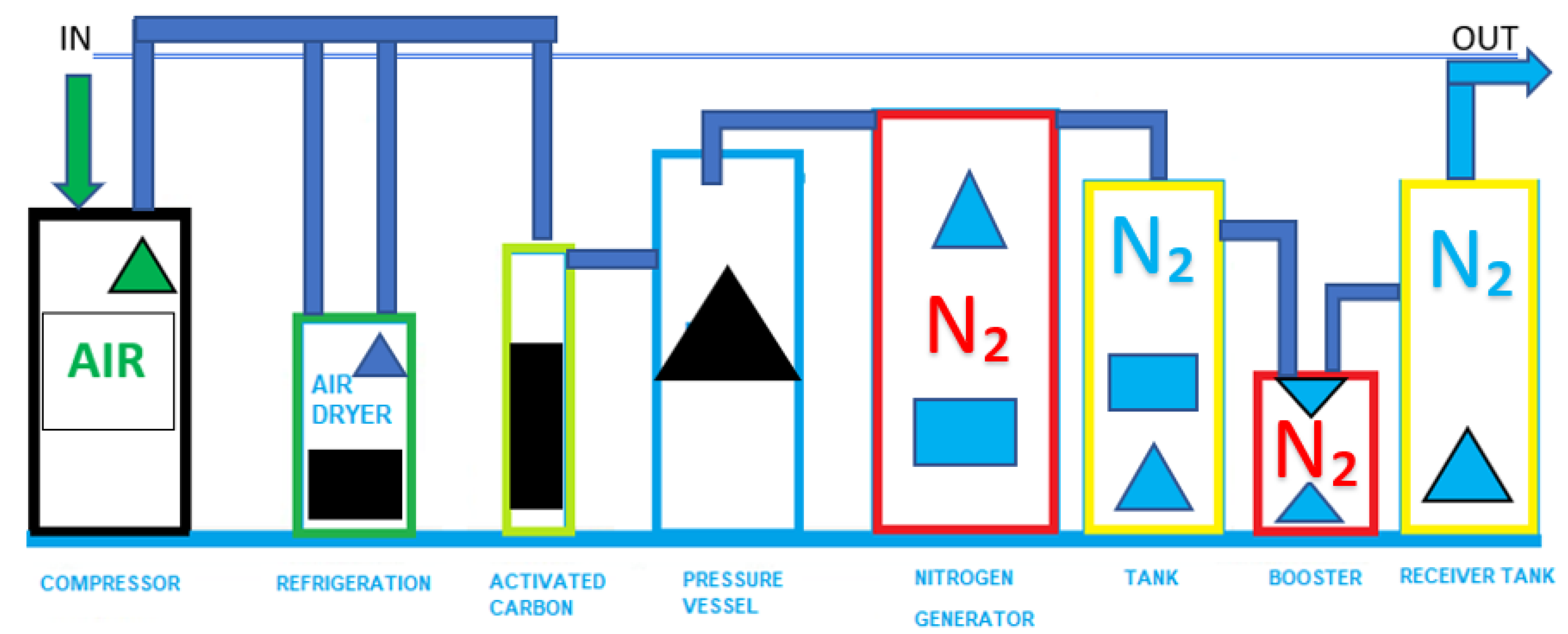
2.1. Nitrogen Generator System

Nitrogen generators operate on the Pressure Swing Adsorption (PSA) principle to produce a continuous stream of nitrogen gas from compressed air. Two towers are filled with carbon molecular sieves (CMS) [48]. Pretreated compressed air enters the bottom of the on-line tower and follows up through the CMS. Oxygen and other trace gasses are preferentially adsorbed by the CMS, allowing nitrogen to pass through. After a pre-set time, the on-line tower automatically switches to regenerative mode, venting contaminants from the CMS [49]. A carbon molecular sieve differs from ordinary activated carbons in that it has a much narrower range of pore openings [50]. This allows small molecules such as oxygen to penetrate the pores and be separated from nitrogen molecules which are too large to enter the CMS. The larger molecules of nitrogen by-pass the CMS and emerge as the product gas [51]. A typical PSA nitrogen generator flow diagram is shown in Figure 1. The fundamental technology involves the separation of nitrogen from oxygen by passing air through a bed of adsorbent, typically a carbon molecular sieve (CMS). Under pressure, the CMS material preferentially adsorbs oxygen and system operation moisture while passing nitrogen through the vessel. During generator operation, the CMS becomes saturated with oxygen. The CMS shall be systematically regenerated by desorbing the oxygen and moisture at low pressure [52]. The air compressor in the nitrogen generator suctions air into the system. The air that was suctioned flows through an air dryer and the air dryer will dry the air at the dew point of 3 °C. Then, dried air will be filtered by 1- and 0.01-micron filter and carbon filter, respectively. Quality air must be oil free, and it will extend the cycle life of the CMS (Carbon Molecular Sieve). Normally, a CMS can be used for 8–10 years. After that, compressed dried air is compressed into a storage tank before it is used to generate gaseous nitrogen. The nitrogen generator consists of 2 tanks of CMS where the first tank absorbs oxygen and the second tank separates nitrogen. These tanks switch functions with each other. Then, 10% of gaseous nitrogen, which still contains oxygen, will be transferred to another CMS tank to separate oxygen again until the required amount is obtained and stored in another storage tank. The purity of nitrogen will be detected by a nitrogen analyzer before use as shown in Figure 1 and Table 1 [53,54].

2.2. Nitrogen Booster System

As for the additional installation of the auxiliary machine, high-pressure nitrogen generators for using nitrogen booster pumps are used due to its favorable physical and chemical properties as gaseous nitrogen is currently used in various industrial blanketing, purging, and flushing operations. As a result, the demand for high-pressure nitrogen generators has surged. The nitrogen booster works according to the principle of a pressure relay valve, where compressed air is used as the driving force. Low pressure is applied to a large surface, which in turns applies high pressure to a small surface [55], as shown in Figure 1 with detail shown in Table 1.
The developed equipment is the all-in-one for high pressure nitrogen as an alternative for gas nitrogen due to its ease of installation, high reliability, and supreme energy efficiency.

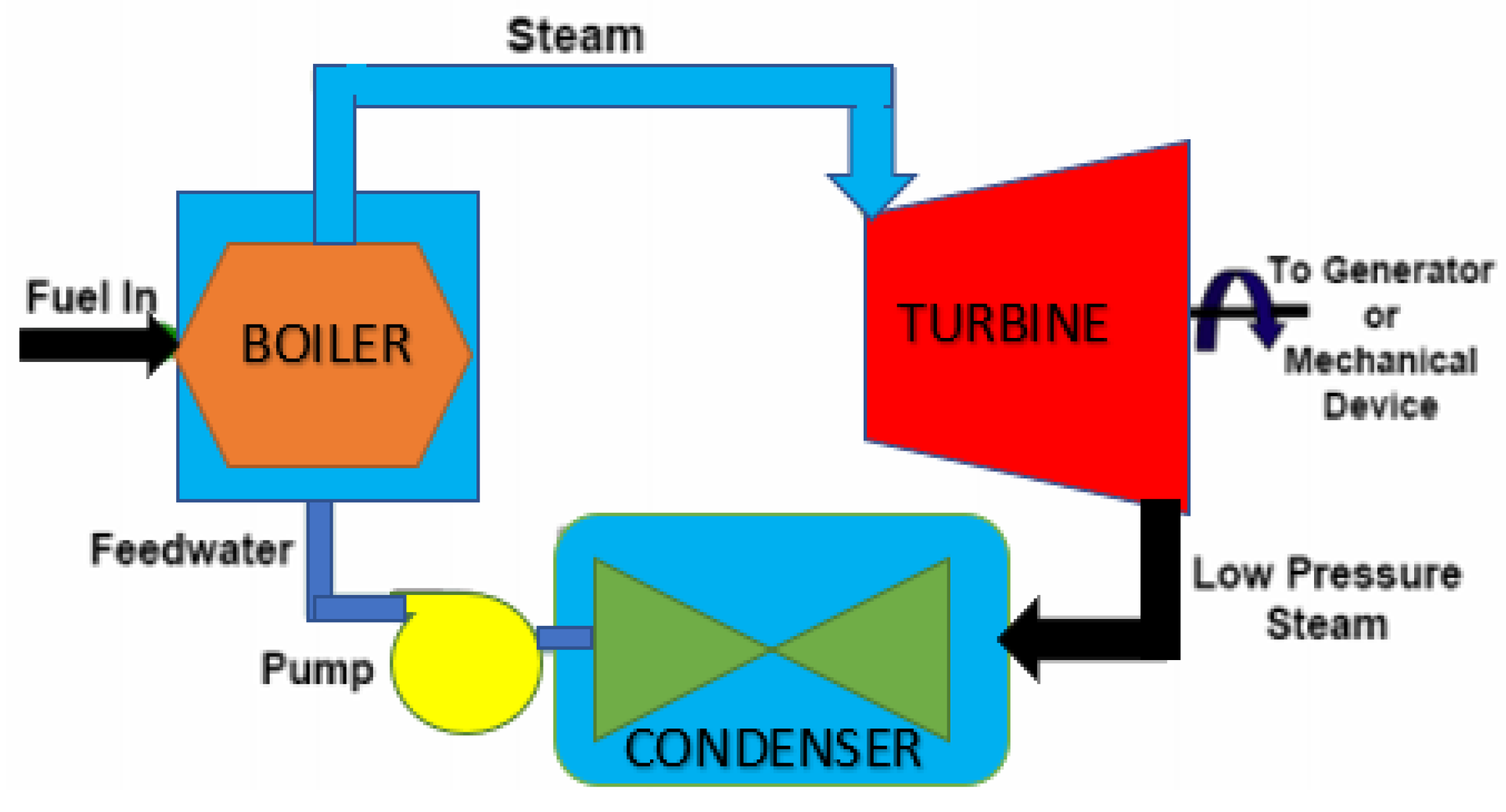
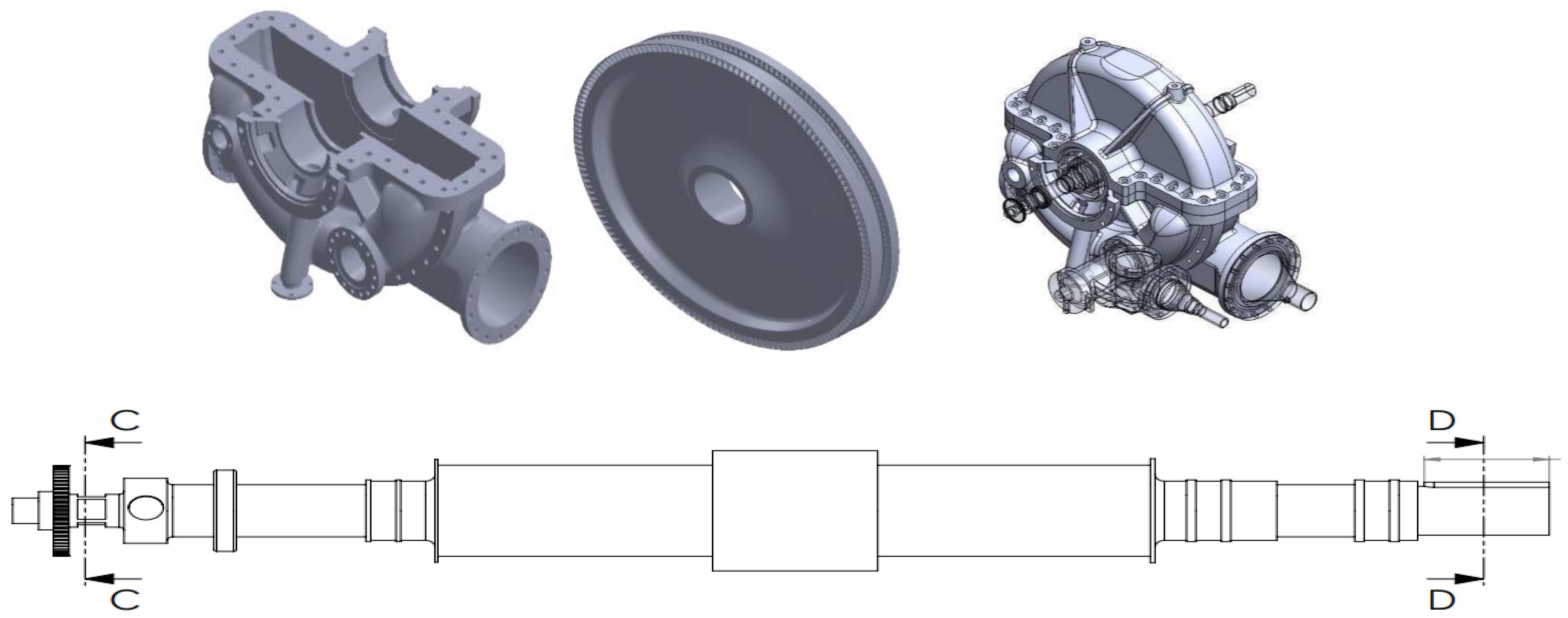
2.3. Injection Steam Turbine Engine

The injection turbine is able to maximize the use of the total energy of the inlet steam flow. Therefore, this type of turbine is used for power utilities that want to supply as much electricity as possible to consumers. The economics of steam turbine applications depend primarily upon two factors—choosing the right type and size of machine (viz. back pressure or injection) [56] and correctly integrating it with the thermal demand process in accordance with the appropriate placement principle of pinch analysis [57] as shown in Figure 2 [58,59,60]. Injection steam turbines have an efficiency in the range ηe = 36 to 42%. From this, it follows that only a small portion of heat released in the process of fuel combustion is transformed into effective work. An injection steam turbine machine is highly efficient in power generation [61], especially for medium and large scale industies. An injection steam turbine usage leads to immediate fuel cost savings on coal, biomass, solid waste, wood chips, refinery residual oil and refinery off gases [27], as shown in detail in Table 2 [58].

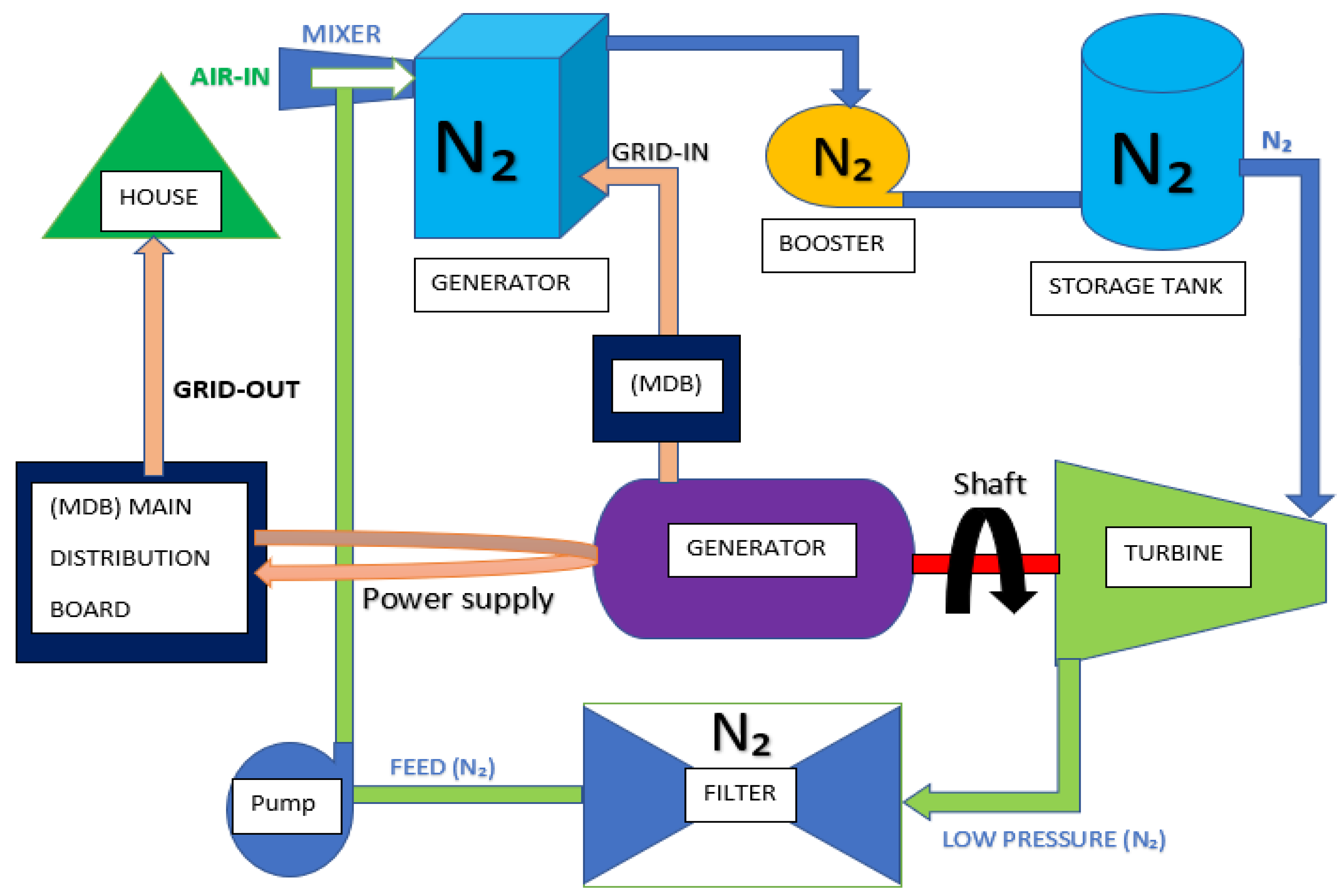
2.4. Electric Generator Systems

In addition to the installation of the auxiliary machine, a generator is a device that converts motive power (mechanical energy) into electrical power for use in an external circuit. Sources of mechanical energy include steam turbines, gas turbines, water turbines, internal combustion engines, wind turbines, and even hand cranks. Generators provide nearly all of the power for electric power grids. The reverse conversion of electrical energy into mechanical energy is done by an electric motor, and motors and generators have many similarities. Many motors can be mechanically driven to generate electricity [62], as shown in Figure 3.
A conceptual model of a nitrogen turbine engine (NTE) is shown in Figure 3. The study also recognizes that: (1) energy is neither created nor destroyed but can be converted into forms (the first law of thermodynamics); and (2) energy comes from the physical environment and ultimately returns there (the law of conservation of energy) [63]. This process starts from a 5000 (Nm3/h) nitrogen generator that generates gaseous nitrogen which is then stored in the storage tank. After that, a nitrogen booster adjusts pressure until the required pressure is obtained. Pressurized gaseous nitrogen is used to drive a turbine of the injection steam engine. Pressure and volume of gaseous nitrogen are measured, and it has to be sufficient for consumption at a rate of 6000 (kWh) for the injection steam turbine engine combined with a generator. After that, low pressure gaseous nitrogen is filtered in the filter chamber. Then, a pump suctions clean gaseous nitrogen from the filter chamber and transfers the gas to a mixer room and starts the circulating cycle. This process preserves energy used in the system. Some of the generated electrical power is used to operate the machine and the remainder is for commercial use.

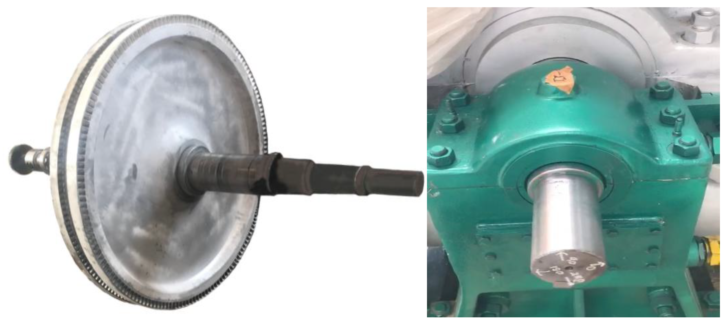
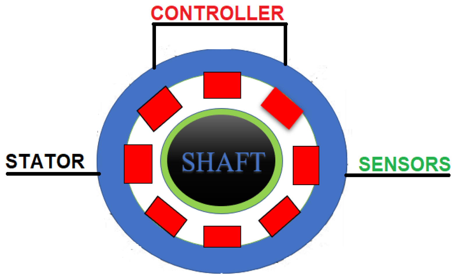
2.5. Magnetic Bearing System

The magnetic bearing positions the rotor using four electromagnets, each composed of a stator component and a rotor component. Opposite electromagnets are adjusted to pull against one another. When an external force causes the rotor to change position, the movement is identified by position sensors. The electronic control system responds by adjusting the current flowing through the respective electromagnets, returning the rotor to its original position. The axial magnetic bearing positions a rotor axially using electromagnetic forces pulling in opposition on the collar as shown in Figure 4 [64]. The outcomes of this study’s analysis will aid in the change of materials of this technology as well as aid in the implementation to a wide range of other mechanical systems [65]. Magnetic bearings and systems are ideal for applications demanding high speeds and low vibration. With no physical contact, there is no need for lubrication, repair, or bearing changes. Low energy consumption, active management, repositioning, and built-in vibration management are also benefits of magnetic bearings and systems. Magnetic bearings do not require lubrication, nor do they touch the centrifugal axle shaft (zero touch) as is shown in Figure 5 [66,67,68].

2.6. Computational Fluid Dynamics (CFD)

Computational Fluid Dynamics (CFD) is a simulation program which was developed as a tool to analyze fluid dynamics. It was used to analyze the flow of gaseous nitrogen and steam in the experiments carried out for this paper. This program is also used to analyze and measure the efficiency of injection steam turbines resulting in minor adjustments which bring operational efficiency as close to optimal as possible. The results after fluid dynamics were analyzed were used to compare efficiency between the gaseous nitrogen turbines and the steam turbines. Then, internal centrifuge systems such as shafts, turbines, and axles were altered in accordance with analysis by the (CFD) program as shown in Figure 6 [69,70]. After the machine was modified in line with advanced engineering principles, it could be used more practically in a variety of new scenarios. This modified machine is a prototype and would be for commercial use [71,72].
The data used for analysis in this paper were obtained from real manufacturers from a variety of countries including China, Germany, and the USA. After the data were obtained, they were reviewed and used as a basis of knowledge as shown in Table 3 [58,73].

3. Theoretical Implications

This study offers theoretical contributions to several research streams. The first steam turbine used for power generation was invented in 1884 [27]. It has been 137 years that we have now depended on the Rankine cycle theory [25] which describes the thermodynamic cycle [26]. However, this theory has a major drawback in that it causes pollution. The Rankine cycle needs to burn natural resources such as fossil fuels, causing high temperature reactions with water in order to create high pressure steam. After the steam is generated, it is used to drive the turbine and the turbine will then drive the steam turbine engine. The steam turbine engine is assembled with the generator to produce mechanical power which is transformed to electrical power. Then, electrical power is transferred to the transformer system and it becomes electrical power which is the most common form of energy used by people today. Some progress has been made in the clean energy field, such as solar cells which depend mainly on solar power, wind turbines which use wind power, and hydropower which uses water as a source to generate power; yet, these three technologies have limitations in power generation as they cannot operate for 24 h continuously. Moreover, they have both direct and indirect impacts on the environment. As mentioned previously, injection steam turbines were invented to resolve those drawbacks. The injection steam turbines save water used to heat up fossil fuels in order to generate high pressure steam, which is used to drive the turbines. The system is designed to push the remaining low-pressure steam into the condenser and the steam can be reused in a condenser unit by pump. This will save energy on the steam consumption rate of up to 20% [30,31,32,33]. Therefore, the authors see opportunities to develop conventional electrical power generation to be a better technology. In the authors’ point of view, the conventional injection steam turbines should be improved by being combined with a nitrogen generator. The nitrogen generator generates gaseous nitrogen from the air that exists in nature. The nitrogen generator separates nitrogen from air, then 78% of gaseous nitrogen is used to drive the turbine and the injection steam turbine instead of using steam. This applied technology is based on the original technology, but it is advanced by using the cooling power of gaseous nitrogen to drive the turbine in the input process instead of using the heat power of steam as it has been used for decades. Additionally, the original theory is applied by the second law of thermodynamics which describes the refrigerating cycle and heat pump cycle. It explains how the system suctions air from outside to transform heat from low temperature to high temperature; this is called the refrigerating cycle and heat pump cycle. Both the refrigerating cycle and heat pump cycle are similar to a reversed Rankine cycle. However, the primary difference among these three theories is flow direction. The refrigerating cycle and heat pump cycle need a compression stroke. The compression stroke is divided into two systems which are the compressor vapor compression refrigeration cycle and the absorption refrigeration cycle. The compression stroke changes steam pressure caused by density of the changing temperature [39]. Moreover, the engine needs to be redesigned, and this will be a revolution of electrical power generation which is similar to vertical rocket landing and electric vehicles. Vertical rocket landing and electric vehicles preserve the environment and limit the overuse of natural resources. Numerous studies have been conducted to find possibilities of applying gaseous nitrogen to generate electrical power. It was found that an American inventor succeeded in patenting his work in 2015 in the United States by using liquid nitrogen to drive the turbine and injection steam turbine of thermal power plants. By applying liquid nitrogen, the water in the cooling system saved energy by up to 30% [42]. Furthermore, inventors patented their European Patent in Brazil in 2007 by using liquid nitrogen to pressurize power generation systems to generate and merchandise electrical power in off grid areas [74]. These two patents used and applied liquid nitrogen. In 1982, David G. Elliott used gaseous nitrogen to pressurize the turbines and the result was compared to hydro pressure, which was published in “Theory and Tests of Two-Phase Turbines”. This became a part in NASA’s work NASA Task Order RD 152, Amendment 266. Hence, the authors have carefully considered that the potential of gaseous nitrogen to revolutionize energy production is extremely high as it possesses most of the similar properties to steam, but it has more advantages. First, gaseous gas is generated more easily than steam. Second, the system that generates gaseous nitrogen does not require a complicated process of installation and it can be installed and moved easily. Third, it does not need a burning process, so it does not cause pollution. It is also crucial to apply magnetic bearings to the centrifugal axle shaft system and turbines as this will not cause pollutants. Magnetic bearings do not require lubrication nor do they touch the centrifugal axle shaft (zero touch) [66,75]. A firm in Japan and the United States suggested that the installation of magnetic bearings to compressor technology of centrifugal chillers can save cost up to 42.3–50%/year [76,77,78]. Reviews of technologies that use magnetic bearings with a compressor motor to avoid the touch between the axis and the other metal surfaces were conducted. The energy consumption rate in the system was measured and it was found to be practical when adopted in industries. In addition to magnetic bearings, artificial intelligence (AI) and CFD programs should be applied to the system as well [69,79,80,81]. They are used with this technology to analyze and control nitrogen gas flow in the machine to provide a more precise evaluation and make minor adjustments resulting in greater efficiency. They also support the hypothesis of the original theory that the turbine was designed to be high heat proof and corrosion proof, both of which can be caused by steam. Nevertheless, the modified technology uses 40 °C gaseous nitrogen and there are possibilities to design turbine and axle shafts that can withstand 40 °C temperature and they can be altered to be lightweight to fit nitrogen pressure. Through modifications and these fairly simple components, a truly green technology can be attainable.

4. Managerial Implications

This review provides insight into the improvement in function of electrical power generation plants. The lead author, who has been working in the gas and oil field for more than 10 years while studying for a PhD, has just published an article in the Environment and Natural Resources Journal titled “Treatment of Flue Gas from an Infectious Waste Incinerator using the Ozone System”, and carried out additional research in “Hospital Trash Infection Disposal to Reduce the Emission of Pollutant into the Atmosphere using Ozone Technology”. With the experience the lead author has gained, the author has become a person who is concerned about humans’ health and the impacts human activity has on the environment. With a strong passion to solve environmental issues, the author is confident that this technology will be a significant contribution to preserving our environment and tackling the issue of climate change in the future. The author has established a team and has found many innovative technologies from around the world which can be modified to solve environmental issues. One of these is the idea of using gaseous nitrogen to drive a turbine generating electrical power instead of using steam. Authors have illustrated the findings of the technologies they have been reviewing in Table 1.
Table 4 is used to analyze the feasibility for this project. After conventional injection steam turbines and gaseous nitrogen steam turbines were compared, the cost of the injection steam turbine engine and the generator must be considered as well. A manufacturer from China estimated the injection steam turbine cost at 1,529,519 (USD). After the engine specification was considered, it was found that the 6000 (kW/h) with 8000 (rpm) engines can heat the temperature to 435 °C to generate steam. The steam consumption rate is 6.36 (kg/s) and the steam pressure rate is 34.3 (bar). This type of engine is the most economical for steam consumption. A nitrogen generator is another factor that must be considered. It was revealed that a 5000 (Nm3/h) nitrogen generator with 40 °C temperature can perform a generation rate at 1.73 (kg/s). This was the most powerful generator observed in this study. Furthermore, a nitrogen booster plays an important role in the system. It is a piece of add-on equipment that increases gas pressure in the tanks to be as high as the steam pressure of a conventional injection steam turbine. The nitrogen booster distributes the density of gaseous nitrogen. The nitrogen booster which was selected for this project can generate pressure of up to 300 (bar). After the electricity consumption rate of the motor (kW/h) of the nitrogen generator was considered, it was found that there were three parts of the motor which needed electricity to operate continuously; however, the compressor motor consumed the most electricity. Four compressor motors consumed 2400 (kW/h) in total which cost 6,118,078 USD. When compared to the total power generation of 6000 (kW/h), the remaining electricity was 3600 (kW/h) as shown in Table 4 [58].
Therefore, to start a revolution changing the conventional technology to be a truly green technology, magnetic bearing innovation must be applied. The magnetic bearing will improve the conventional centrifugal axle shaft system. The overall rotation system will be changed to be magnetic-zero touch and zero friction. Up to 50% of the total energy consumption in the system will be saved [76,77,78]. Overall project cost reduction, for instance, could be easily attained by going from four nitrogen generators to two, electrical power needed for machine operation would be halved from 2400 (kW/h) to 1200 (kW/h) which means more remaining power to sell, leading to more profit. Moreover, the cost of the nitrogen generator will lead to savings of up to 3,059,039 (USD).

5. Results and Discussion

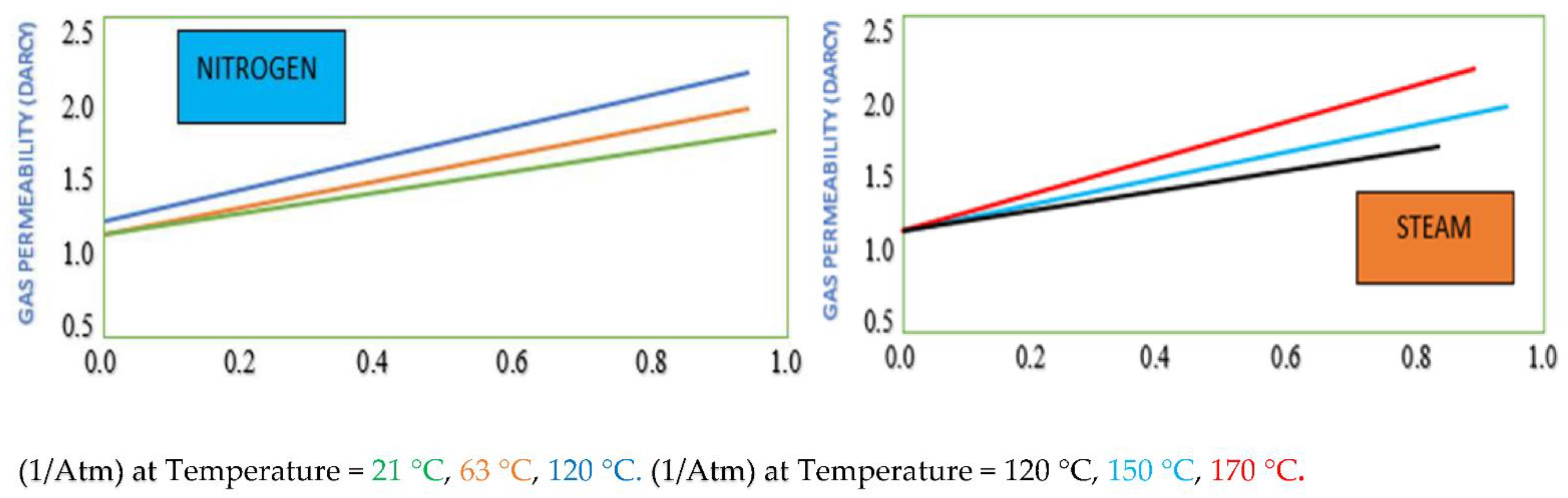
5.1. Comparison of Effectiveness and Properties of Nitrogen and Steam

A review of the theoretical framework found that experiments to measure nitrogen/water two-phase relative permeabilities were conducted at a room temperature of approximately 21 °C. The gas distribution factors of nitrogen and steam flow through porous media were measured at different temperatures up to approximately 170 °C. It was also suggested that steam needs to be burned from fossil fuels before it can generate desired temperature levels, which means it costs fuel [27]. In this experiment, the steam temperatures tested were 120, 150, and 170 °C, while the nitrogen temperature was kept at 21 °C. Then, the nitrogen temperature was increased to 63 and 120 °C [82]. It was obvious that both the nitrogen and steam gas distribution factors increased with temperature. The steam gas distribution factor was significantly less than that of nitrogen at the same temperature of 120 °C, as is shown in Figure 7 and Figure 8 [83].
The statement mentioned above was coherent with the data shown in Table 4 which compared the result of the nitrogen injection turbine and the steam turbine. After that, different pressure and temperature adjustments were made to examine the density of nitrogen and steam. It was found that after the pressure was increased to 1 bar, the nitrogen temperature was stable at 40 °C and the nitrogen density was 1.081 (kg/m3), while steam temperature was 99.63 °C and the steam density was 0.590 (kg/m3). Then, when the pressure was increased to 10 bar, it revealed that the nitrogen temperature was still stable at 40 °C and the nitrogen density was 10.600 (kg/m3), while steam temperature was 179.88 °C and the steam density was 5.147 (kg/m3). Lastly, when the pressure was increased to 30 (bar), it can be seen that the nitrogen temperature remained at 40 °C and the nitrogen density was 32.300 (kg/m3), while steam temperature was 233.84 °C and the steam density was 15.009 (kg/m3). It was clear that the higher the pressure, the greater the gas distribution of nitrogen generated [84]. Similar results were obtained which stated that when compressing more pressure into the turbine, higher density was generated. It can be concluded that when temperature and pressure increased, the distribution levels of nitrogen became significantly higher as shown in Table 4. There is a possibility of using nitrogen to generate electrical power instead of steam, or nitrogen could be combined with steam to drive the engine of the injection steam generating electrical power as well [42,85].

5.2. Efficiency Comparison of N2 Generator and with injection Steam Turbine Engine

After the nitrogen system and injection steam turbine were compared, it was found that with 5000 (Nm3/h) at a temperature of 40 °C and pressure of 34.30 bar, the nitrogen generator can produce a gas flow rate of 6261.10 (kg/h) [86], which was not enough to be used to drive the propeller which generates mechanical power that drives an electricity generator in the systems with conventional injection steam turbine [87,88,89]. Then, a 6000 kW/h injection steam turbine with a rotation speed of 8000 (rpm) was studied and it was found that steam pressure of 34.30 bar was required [90] After that, the injection steam turbine was compared with a nitrogen generator and it was obvious that the nitrogen booster combined with a nitrogen generator generated significantly higher pressure of up to 300 bar. Moreover, the engine of the injection steam turbine was designed to be used with a steam temperature of 435 °C. In contrast, the nitrogen generator was designed to be used with a lower temperature of 40 °C. It is crucial to analyze the consumption rate of steam used in the conventional injection steam turbine. The consumption rate of the conventional injection steam turbine was 6.36 (kg/s) which consumed more steam energy than the 5000 (Nm3/h) nitrogen generator which consumed steam energy at a rate of only 1.73 (kg/s). This point led to the development of a new engine [73] called the Nitrogen Turbine Engine (NTE). Therefore, one c injection steam turbine is required to be used with four nitrogen generators in order to generate enough nitrogen gas driving 6000 (kW/h) conventional injection steam turbines to reach the most efficient and effective electrical power generation [86] as shown in Table 5. The break-even point should also be considered to save excessive energy used to generate electrical power. It is also crucial to apply magnetic bearings to the centrifugal axle shaft system and turbines as this will not cause pollutants. Magnetic bearings do not require lubrication, nor do they touch the centrifugal axle shaft (zero touch) [66,75]. A firm in Japan and the United States suggested that the installation of magnetic bearings to compressor technology of centrifugal chillers can save costs up to 42.3–50%/year [76,77,78]. Reviews of technologies that use a magnetic bearing with a compressor motor to avoid the touch between the axis and the other metal surfaces were conducted. The energy consumption rate in the system was measured and it was found to be practical when adopted in industries. In addition to magnetic bearings, artificial intelligence (AI) and CFD programs should be applied to the system as well [69,79,80,81]. They are used with this technology to analyze and control nitrogen gas flow in the turbine to provide a more precise evaluation and change materials resulting in a more efficient technology. They also support the hypothesis of the original theory that the turbine was designed to be high heat proof and corrosion proof, both of which can be caused by steam. Nevertheless, the modified technology uses 40 °C gaseous nitrogen and there are possibilities to design turbine and axle shafts that can withstand 40 °C temperature and they can be altered to be lightweight to fit nitrogen pressure as shown in Table 6 [58].

6. Conclusions

This review explored the reverse engineering of hot to cold gas conversion and obtained data from real manufacturers which was then applied to nitrogen turbines used for generating electrical power. The results of the review found possibilities of using 5000 (Nm3/h) of nitrogen instead of steam with the injection steam turbine engine with a 6000 (kW/h) capacity as nitrogen and steam possessed different properties in terms of gas nitrogen density; pressure was increased by a booster and brought up to 300 (bar) for driving the turbine with greater force. Moreover, when the production rate of the nitrogen generator was studied, it was found that the amount of nitrogen gas obtained from the nitrogen generator was 1.73 (kg/s), which was not sufficient for the energy consumption rate of 6.36 (kg/s) found in conventional steam turbines. To be more specific, four nitrogen generators are required to generate sufficient nitrogen gas for one injection steam turbine. Overall, this technology warrants further examination, including centrifuged systems, and should be studied as our research shows implementation can reduce costs by almost 50%. After all the machines were combined, there was a high tendency to save on energy consumption used to generate nitrogen and injection turbine engines. Furthermore, artificial intelligence (AI) or CFD software was used as a tool to perform a simulation solving complex issues. AI evaluated nitrogen gas flow in the centrifuged systems and then led to a material change plan in order to increase precision and further advancement of this technology. Using free energy, nitrogen, to drive the turbines and to generate electrical power will greatly reduce power generation costs resulting in directly lowering electrical power utility bills for people. Therefore, this has the potential to become practical and once it is practical, commercial adoption of electric power generated from nitrogen turbines would promote economic growth in the future.

7. Suggestions

Magnetic bearings have not been used widely with the centrifuged system of the engine in the electrical power generation industry, especially in Thailand. This could lead to both opportunities and threats in the power generation industry in Thailand. Therefore, a study of magnetic bearings needs to be conducted. In addition, since this is an innovation, there are challenges in regard to trust, provability, and backing from investors and financial institutions, so a feasibility study of investment should be conducted as well. The authors have already thoroughly analyzed the economic data for the viability of investment in this project. These eight benefits would not only be very useful but are also reliable enough to support this project. This project provides immense benefits to the world and contains information that has been carefully and systematically synthesized to help decision making and action planning. To help preserve the already fragile environment and as a solution to a host of problems currently being faced, urgent implementation is advised.

8. Benefits of the Study

  • This technology can be installed anywhere that is well-ventilated, so it is suitable for rural areas and off-grid areas.
  • The size of the engine is around 1–6000 kWh, so it is a moveable operation and a suitable method to increase economic growth around the world.
  • This technology does not require fuel burning; it causes zero air pollution.
  • This technology is a match for large scale industries, shopping malls, and living communities.
  • This technology would disrupt huge power generation plants which use natural resources, especially the nuclear plants.
  • Logistics costs of power generation will decrease greatly, no more need for transmission lines.
  • This is the greenest and the most sustainable technology for electrical power generation.
  • The cost of electrical power will decrease all over the world, which is beneficial for everyone.

Author Contributions

Conceptualization, W.V., K.K., S.S., P.K., U.T., J.S. and B.B.; Formal analysis, W.V., K.K., S.S., P.K., U.T. and J.S.; Methodology, W.V. and K.K.; Writing—original draft, W.V. and K.K.; Writing—review and editing, W.V., K.K., S.S., P.K., U.T. and J.S. All authors have read and agreed to the published version of the manuscript.

Funding

This research was provided with financial support and technical support by Energy Experts Thailand Co., Ltd.

Conflicts of Interest

The authors declare no conflict of interest. The funder had no role in the design, collection, analyses, or interpretation of data, the writing of the manuscript, or the decision to publish the results.

References

  1. Mahmoud, H.K. Lecyure 4: CHAPTER 2 Energy Sources; Faculty of Engineering, Department of Electrical Engineering: Giza, Egypt, 2017. [Google Scholar]
  2. IRENA. Renewable Power Generation Costs in 2019; International Renewable Energy Agency: Abu Dhabi, United Arab Emirates, 2020. [Google Scholar]
  3. Sagliano, M.; Ishimoto, S.; Macés-Hernández, J.A.; Seelbinder, D.; Dumont, E. Guidance and Control Strategy for the CALLISTO Flight Experiment. In Proceedings of the 8th European Conference for Aeronautics and Aerospace Sciences (Eucass), Madrid, Spain, 1–4 July 2019. [Google Scholar]
  4. Bysani, S.K.K.; Karpur, A.; Arun, N. Vertical Landing Rockets. In Proceedings of the 4th TMAL02 Expert Conference, Linköping, Sweden, 14 October 2019; Volume 8, pp. 33–34. [Google Scholar]
  5. Dongliang, W.; Qifeng, C.; Luohaijun, L.M. A Landing Buffer System for Vertical Takeoff and Vertical Landing Reusable Launch Vehicle. In Proceedings of the 8th European Conference for Aeronautics and Aerospace Sciences (Eucass), Madrid, Spain, 1–4 July 2019. [Google Scholar]
  6. Ferrante, R. A Robust Control Approach for Rocket Landing. Master Thesis, School of Informatics, University of Edinburgh, Edinburgh, Scotland, 2017. [Google Scholar]
  7. Nonaka, S.; Nishida, H.; Kato, H.; Ogawa, H.; Inatani, Y. Vertical landing aerodynamics of reusable rocket vehicle. Trans. Jpn. Soc. Aeronaut. Space Sci. Aerosp. Technol. Jpn. 2012, 10, 1–4. [Google Scholar] [CrossRef] [Green Version]
  8. Singer, S. The Energy Report: 100% Renewable Energy by 2050; Ecofys B.V.: Utrecht, The Netherlands, 2010. [Google Scholar]
  9. Tromly, K. Renewable Energy: An Overview; National Renewable Energy Laboratory (U.S.): Golden, CO, USA, 2001. [Google Scholar]
  10. Lin, F.; Wang, Z.; Zhang, Z.; He, Y.; Zhu, Y.; Shao, J.; Yuan, D.; Chen, G.; Cen, K. Flue gas treatment with ozone oxidation: An overview on NOx, organic pollutants, and mercury. Chem. Eng. J. 2020, 382, 123030. [Google Scholar] [CrossRef]
  11. Vattanapuripakorn, W.; Khannam, K.; Sonsupap, S.; Tongsantia, U.; Sarasamkan, J.; Bubphachot, B. Treatment of Flue Gas from an Infectious Waste Incinerator using the Ozone System ARTICLE INFO ABSTRACT. Environ. Nat. Resour. J. 2021, 19, 348–357. [Google Scholar] [CrossRef]
  12. Chaudhary, G.; Lamb, J.J.; Burheim, O.S.; Austbø, B. Review of Energy Storage and Energy Management System Control Strategies in Microgrids. Energies 2021, 14, 4929. [Google Scholar] [CrossRef]
  13. Halleux, V. New EU Regulatory Framework for Batteries: Setting Sustainability Requirements; EU Legislation in Progress; European Parliament: Brussels, Belgium, 2021. [Google Scholar]
  14. NERC. Energy Storage: Impacts of Electrochemical Utility-Scale Battery Energy Storage Systems on the Bulk Power System; NERC: Atlanta, GA, USA, 2021. [Google Scholar]
  15. Fordham, E.; Allison, W. Safety of Grid Scale Lithium-ion Battery Energy Storage Systems. 2021. Available online: https://www.researchgate.net/publication/352158070_Safety_of_Grid_Scale_Lithium-ion_Battery_Energy_Storage_Systems (accessed on 25 September 2021).
  16. U.S. Department of Energy Battery Storage in the United States. An Update on Market Trends; U.S. Department of Energy Battery Storage in the United States: Washington, DC, USA, 2021. [Google Scholar]
  17. Ma, J.; Li, Y.; Grundish, N.S.; Goodenough, J.B.; Chen, Y.; Guo, L.; Peng, Z.; Qi, X.; Yang, F.; Qie, L.; et al. The 2021 battery technology roadmap. J. Phys. D Appl. Phys. 2021, 54, 183001. [Google Scholar] [CrossRef]
  18. Vérez, D.; Borri, E.; Crespo, A.; Mselle, B.D.; de Gracia, Á.; Zsembinszki, G.; Cabeza, L.F. Experimental Study on Two PCM Macro-Encapsulation Designs in a Thermal Energy Storage Tank. Appl. Sci. 2021, 11, 6171. [Google Scholar] [CrossRef]
  19. Patrice, N.; Andrew, N.; Cesare, B.; Christofer, L.; Hector, R.; Ho, K.H.; Kunal, G.; Mamoon, A.; Neil, A.; Timo, L.; et al. Battery Storage; Battery Storage IMIA Working Group Paper. 2019. Available online: https://www.imia.com/wp-content/uploads/2020/01/IMIA-WGP-112-19-Battery-Storage.pdf (accessed on 25 September 2021).
  20. Kocer, M.C.; Cengiz, C.; Gezer, M.; Gunes, D.; Cinar, M.A.; Alboyaci, B.; Onen, A. Assessment of Battery Storage Technologies for a Turkish Power Network. Sustainability 2019, 11, 3669. [Google Scholar] [CrossRef] [Green Version]
  21. Deotti, L.; Guedes, W.; Dias, B.; Soares, T. Technical and Economic Analysis of Battery Storage for Residential Solar Photovoltaic Systems in the Brazilian Regulatory Context. Energies 2020, 13, 6517. [Google Scholar] [CrossRef]
  22. U.S. Department of Energy Spotlight: Solving Industry’s Energy Storage Challenges; Office of Technology Transitions (OTT): Washington, DC, USA, 2019.
  23. Zhongming, Z.; Linong, L.; Wangqiang, Z.; Wei, L. Handbook on Battery Energy Storage System; Asian Development Bank: Metro Manila, Philippines, 2018. [Google Scholar]
  24. Osigwe, E.O.; Gad-Briggs, A.; Nikolaidis, T.; Jafari, S.; Sethi, B.; Pilidis, P. Thermodynamic Performance and Creep Life Assessment Comparing Hydrogen-and Jet-Fueled Turbofan Aero Engine. Appl. Sci. 2021, 11, 3873. [Google Scholar] [CrossRef]
  25. Enslin, J. Rankine Cycle Efficiency Increase by the Regenerative Recovery of Historically Rejected Heat. Bioenergetics 2018, 7, 155. [Google Scholar]
  26. Quoilin, S.; Lemort, V. The Organic Rankine Cycle: Thermodynamics, Applications and Optimization; UNESCO-EOLSS: Oxford, UK, 2011. [Google Scholar]
  27. CHP. Catalog of CHP Technologies. Section 4. Technology Characterization—Steam Turbines; U.S. Environmental Protection Agency Combined Heat and Power Partnership: Washington, DC, USA, 2015. [Google Scholar]
  28. Owusu, P.A.; Asumadu-Sarkodie, S. A review of renewable energy sources, sustainability issues and climate change mitigation. Cogent. Eng. 2016, 3, 1167990. [Google Scholar] [CrossRef]
  29. Jović, M.; Lakovic, M.; Bogdanovic-Jovanovic, J. Review of opportunities for steam condenser performance improvements in power plants. In Proceedings of the International Conference Power Plants 2016, Zlatibor, Srbija, 23–26 November 2016. [Google Scholar]
  30. Jamróz, M.; Piwowarski, M.; Ziemiański, P.; Pawlak, G. Technical and Economic Analysis of the Supercritical Combined Gas-Steam Cycle. Energies 2021, 14, 2985. [Google Scholar] [CrossRef]
  31. Kermeli, K.; Worrell, E. Energy Efficiency and Cost Saving Opportunities for Breakfast Cereal Production: An ENERGY STAR® Guide for Energy and Plant Managers; U.S. Environmental Protection Agency, Utrecht University: Utrecht, The Netherlands, 2018. [Google Scholar]
  32. Dosa, I.; Petrilean, D. Efficiency Assessment of Condensing Steam Turbine. In Advances in Environment, Ecosystems and Sustainable Tourism; WSEAS Press: Brasov, Romania, 2013; pp. 203–208. [Google Scholar]
  33. Albert, P. Steam Turbine Thermal Evaluation and Assessment; Report No. GER-4190 GE; Power Systems: Schenectady, NY, USA, 2000. [Google Scholar]
  34. Maxwell, G. Synthetic Nitrogen Products: A Practical Guide to the Products and Processes; Springer Science & Business Media: Berlin/Heidelberg, Germany, 2004. [Google Scholar]
  35. Khalil, A. Production of nitrogen from the air during cryogenic process and analyzing the air feed in raslanlf utilities for oil & gas. In Proceedings of the Benghazi International Conference and Exhibition of Oil and Gas 2018, Benghazi, Libya, 25–27 October 2018. [Google Scholar]
  36. Pressure Testing for Strength and Leak Tightness. Available online: https://www.coolconcerns.co.uk/imagelib/pdfs/CS_3_Pressure_testing.pdf (accessed on 7 July 2021).
  37. Realzero Guide to Good Leak Testing; Mill Lane: Carshalton Surrey, UK, 2009.
  38. Institute of Refrigeration Good Practice Guide 24. Pressurising Installed Systems with Nitrogen to Find Leaks; Mill Lane: Carshalton, UK, 2007. [Google Scholar]
  39. Cengel, Y.A.; Boles, M.A. Thermodynamics, An Engineering Approach, 5th ed.; McGraw Hill: New York, NY, USA, 2006. [Google Scholar]
  40. Fu, Z.G.; Iqbal, T.; Shah, S.J.A.; Khan, H.I. Study on gas turbine performance by nitrogen injection for IGCC power plant. In Proceedings of the 2019 2nd International Conference on Computing, Mathematics and Engineering Technologies (iCoMET), Sindh, Pakistan, 30 January 2019. [Google Scholar]
  41. Ministry of Industry and Trade Guideline for Technical Regulation Volume 2 Design of Thermal Power Facilities Book 3/12 «Gas Turbine»; Trang Tien Ward: Ha Noi, Vietnam, 2013.
  42. Baxter, L.L. Methods and Systems for Generating Power from Aturbine using Pressurized Nitrogen. U.S. Patent No. 8,963,347, 24 February 2015. [Google Scholar]
  43. Da Costa, R.S. Electricity Generation System Based on Nitrogen. U.S. Patent Application No. 11/991,223, 26 March 2009. [Google Scholar]
  44. Armstrong, F. Farnborough and the beginnings of gas turbine propulsion. J. Aeronaut. Hist. Pap. 2020, 2, 2. [Google Scholar]
  45. Clark, D.; Jansen, M.; Montague, G. An Overview of Magnetic Bearing Technology for Gas Turbine Engines; NASA: Hanover, MD, USA, 2004. [Google Scholar]
  46. Brandão, P.; Infante, V.; Deus, A.M. Thermo-mechanical modeling of a high pressure turbine blade of an airplane gas turbine engine. Procedia. Struct. Integr. 2016, 1, 189–196. [Google Scholar] [CrossRef] [Green Version]
  47. Das, T.K.; Halder, P.; Samad, A. Optimal design of air turbines for oscillating water column wave energy systems: A review. Int. J. Ocean Clim. Syst. 2017, 8, 37–49. [Google Scholar]
  48. Lei, L.; Lindbråthen, A.; Zhang, X.; Favvas, E.P.; Sandru, M.; Hillestad, M.; He, X. Preparation of carbon molecular sieve membranes with remarkable CO2/CH4 selectivity for high-pressure natural gas sweetening. J. Membr. Sci. 2020, 614, 118529. [Google Scholar] [CrossRef]
  49. Panah, F.Y. Evaluation of Nitrogen Systems for Fire Suppression in Northern British Columbia Wood Pellet Plants; Wood Pellet Association of Canada: Revelstoke, BC, Canada, 2020. [Google Scholar]
  50. Carbon Molecular Sieves and Other Porous Carbons Synthesis and Applications. Available online: http://www.megacarbon.com/techlit/carmolsiv.pdf (accessed on 7 July 2021).
  51. Zhang, L. Experimental Investigation on Hydrogen Isotope Separation in Nanoporous Materials. PhD Thesis, University of Stuttgart, Stuttgart, Germany, 2020. [Google Scholar]
  52. Compressed Gas Association. Safe Installation and Operation of PSA and Membrane Oxygen and Nitrogen Generators; HarbourFront Place: Singapore, 2010. [Google Scholar]
  53. Seo, Y.; Jung, J.Y.; Han, S.; Kang, K. Availability Estimation of Air Compression and Nitrogen Generation Systems in LNG-FPSO Depending on Design Stages. Appl. Sci. 2020, 10, 8657. [Google Scholar] [CrossRef]
  54. Maget, H.J. Electrochemical Nitrogen Generators. 2018. Available online: https://www.researchgate.net/publication/325206300_Electrochemical_nitrogen_generators (accessed on 25 September 2021).
  55. Yang, F.; Tadano, K.; Li, G.; Kagawa, T. Analysis of the energy efficiency of a pneumatic booster regulator with energy recovery. Appl. Sci. 2017, 7, 816. [Google Scholar] [CrossRef]
  56. Parvez, M. Steam Condenser; Al-Falah University: Faridabad, India, 2018. [Google Scholar]
  57. Kumana, J. Optimal integration of steam turbines for industrial chp applications. In Proceedings of the 39th Industrial Energy Technology Conference, New Orleans, Louisiana, 20–23 June 2017. [Google Scholar]
  58. Bahrami, S.; Ghaffari, A.; Genrup, M.; Thern, M. Performance Comparison between Steam Injected Gas Turbine and Combined Cycle during Frequency Drops. Energies 2015, 8, 7582–7592. [Google Scholar] [CrossRef] [Green Version]
  59. Banaszkiewicz, M. Steam turbines start-ups. Trans. Inst. Fluid-Flow Mach. 2014, 26, 169–198. [Google Scholar]
  60. Al-Doori, W.H.A.R. Influence of Steam Injection on the Performance of Combined Cycle Power Plant. J. Eng. Appl. Sci. 2011, 6, 390–396. [Google Scholar]
  61. Losowska, M. Embodied Energy Counting of Sustainable Heat, Power and Steel Processes. Master’s Thesis, University of Akureyri, Akureyri, Iceland, 2011. [Google Scholar]
  62. Boland, J.; Chao, Y.H.; Suzuki, Y.; Tai, Y.C. Micro electret power generator. In Proceedings of the Sixteenth Annual International Conference on Micro Electro Mechanical Systems, Kyoto, Japan, 19 January 2003; Volume 2005, pp. 538–541. [Google Scholar]
  63. Al-Zuhairi, M.T.L. Economics of Energy Resources Lecture Notes; Philadelphia University–Jordan Electrical Engineering Department: Philadelphia, PA, USA, 2009. [Google Scholar]
  64. Zhang, W.; Zhu, H. Radial magnetic bearings: An overview. Results Phys. 2017, 7, 3756–3766. [Google Scholar] [CrossRef]
  65. Pewekar, M.; Gaikwad, S. Analysis of Active Magnetic Bearings. Bachelor Thesis, University of Mumbai, Mumbai, India, 2018. [Google Scholar]
  66. Ahad, M.A.; Ahmad, S.M. Investigation of a 2-DOF Active Magnetic Bearing Actuator for Unmanned Underwater Vehicle Thruster Application. Actuators 2021, 10, 79. [Google Scholar] [CrossRef]
  67. Zhao, J.; Xing, L.; Li, S.; Yan, W.; Gao, D.; Du, G. Impact-Rubbing Dynamic Behavior of Magnetic-Liquid Double Suspension Bearing under Different Protective Bearing Forms. Processes 2021, 9, 1105. [Google Scholar] [CrossRef]
  68. Sun, J.; Zhou, H.; Ju, Z. Dynamic stiffness analysis and measurement of radial active magnetic bearing in magnetically suspended molecular pump. Sci. Rep. 2020, 10, 1401. [Google Scholar] [CrossRef]
  69. Shrestha, U.; Choi, Y.-D. A CFD-Based Shape Design Optimization Process of Fixed Flow Passages in a Francis Hydro Turbine. Processes 2020, 8, 1392. [Google Scholar] [CrossRef]
  70. Khan, T.A.; Ahmad, H. CFD-Based Comparative Performance Analysis of Different Nanofluids Used in Automobile Radiators. Arab. J. Sci. Eng. 2019, 44, 5787–5799. [Google Scholar] [CrossRef]
  71. Unsakul, S.; Sranpat, C.; Chaisiriroj, P.; Leephakpreeda, T. CFD-based performance analysis and experimental investigation of design factors of vertical axis wind turbines under low wind speed conditions in Thailand. J. Flow Control Meas. Vis. 2017, 5, 86. [Google Scholar] [CrossRef] [Green Version]
  72. Škerlavaj, A.; Morgut, M.; Jošt, D.; Nobile, E. Decoupled CFD-based optimization of efficiency and cavitation performance of a double-suction pump. J. Phys. Conf. Ser. 2017, 813, 012048. [Google Scholar] [CrossRef]
  73. Technology and Innovation Report 2018—Harnessing Frontier Technologies for Sustainable Development. Available online: https://unctad.org/webflyer/technology-and-innovation-report-2018 (accessed on 7 July 2021).
  74. Da Costa, R.S. Electricity Generation System Based on Nitrogen. European Patent 1929197B1, 12 December 2012. [Google Scholar]
  75. Rao, J.S. Introduction to Magnetic Bearings; Department of Mechanical Engineering, Indian Institute of Technology: Guwahati, India, 2008. [Google Scholar]
  76. Ueda, K.; Hasegawa, Y.; Yawata, N.; Yokoyama, A.; Mukai, Y. First Domestic High-Efficiency Centrifugal Chiller with Magnetic Bearings: The ETI-MB Series. Mitsubishi. Heavy Ind. Tech. Rev. 2014, 51, 82–86. [Google Scholar]
  77. Parker, S.; Blanchard, J. Variable-Speed Oil-Free Centrifugal Chiller with Magnetic Bearings Assessment; Howard, G., Jr., Ed.; Federal Building and US Courthouse: Pine Bluff, AR, USA, 2012. [Google Scholar]
  78. Siebert, M.; Ebihara, B.; Jansen, R.; Fusaro, R.; Morales, W.; Kascak, A.; Kenny, A. A Passive Magnetic Bearing Flywheel. In Proceedings of the 36th Intersociety Energy Conversion Engineering Conference, Savannah, GA, USA, 29 July–2 August 2001. [Google Scholar]
  79. Rogowski, K.; Pawlicki, J. Numerical analysis of the steam flow past the turbine blade stage. J. Mach. Eng. 2017, 17, 102–110. [Google Scholar]
  80. Pennaturu, S.; Issac, P. Evaluating performance of steam turbine using CFD. Int. J. Latest Trends Eng. Technol. 2014, 4, 209–304. [Google Scholar]
  81. Vasmate, S. Computational fluid dynamics (CFD) analysis of intermediate pressure steam turbine. Int. J. Mech. Eng. Robot. Res. 2014, 3, 459. [Google Scholar]
  82. Taxas Instruments. The Engineer’s Guide to Temperature Sensing; Taxas Instruments: Dallas, TX, USA, 2019. [Google Scholar]
  83. Li, K.; Horne, R. Experimental Study of Gas Slippage in Two-Phase Flow. SPE Reserv. Eval. Eng. 2004, 7, 409–415. [Google Scholar] [CrossRef]
  84. Malthe-Sroenssen, A. Chemical Potential and Gibbs Distribution; Universitetet i Oslo: Oslo, Norway, 2013. [Google Scholar]
  85. Khalil, K.M.; Ahmad, A.; Mahmoud, S.; Al-Dadah, R.K. Liquid air/nitrogen energy storage and power generation system for micro-grid applications. J. Clean. Prod. 2017, 164, 606–617. [Google Scholar] [CrossRef]
  86. Cui, M.; Wu, C. Principles of and tips for nitrogen displacement in gas pipeline commissioning. Nat. Gas Ind. B 2015, 2, 263–269. [Google Scholar] [CrossRef] [Green Version]
  87. Technology and Innovation Report 2021—Catching Technological Waves: Innovation with Equity. Available online: https://unctad.org/webflyer/technology-and-innovation-report-2021 (accessed on 7 July 2021).
  88. Using Existing Technology to Build a More Efficient Enterprise. Available online: https://rsmus.com/pdf/wp_using_technology_to_build_efficient_enterprise.pdf (accessed on 7 July 2021).
  89. UN Secretary-General’s Strategy on New Technologies. Available online: https://www.un.org/en/newtechnologies/ (accessed on 7 July 2021).
  90. Bugała, P. Review of design of high-pressure turbine. J. KONES 2017, 24, 67–76. [Google Scholar]
Figure 1. Nitrogen generator flow diagram.
Inventions 06 00062 g001
Figure 2. Schematic of injection steam turbine.
Inventions 06 00062 g002
Figure 3. Schematic conceptual model of the nitrogen turbine engine system (NTES).
Inventions 06 00062 g003
Figure 4. A turbine and shafts.
Inventions 06 00062 g004
Figure 5. Schematic of the cross-section of the magnetic bearing system.
Inventions 06 00062 g005
Figure 6. Components of axle shaft and propeller.
Inventions 06 00062 g006
Figure 7. Comparison of the nitrogen and steam gas distribution effects at different temperatures.
Inventions 06 00062 g007
Figure 8. Comparison of the nitrogen and steam gas distribution factor test.
Inventions 06 00062 g008
Table 1. Properties and specification of (N2) product model: PN-capacity-purity (PN-060) high-capacity PSA nitrogen generation plants.
ParametersValue
Nitrogen purity (%)95–99
Nitrogen flow rate (Nm3/h)5000
Ambient air temperature (°C)40
Nitrogen outlet pressure (bar)13
Nitrogen booster to pressure (bar)1–300
Availability (hours)24
Table 2. Properties and specifications of injection steam turbine product model (BN6-3.43/0.4).
ParametersValue
Rated power (kW/h)6000
Rated speed (rpm)8000
Incoming temperature (°C)435
Pressure into the steam (bar)34.3
Consumption of vapor rate (kg/s)6.36
Availability (hours)24
Table 3. Data used in the analysis of the features and methods of machines from 2 manufacturers for 5.8 (MW/h) product model (SGT-A05 (KB7HE)) and 6 (MW/h) product model (BN6-3.43/0.4).
No.ParametersAnalysis MethodValue
1Electrical generator (kW/h)It depends on the manufacturer’s design.5800/6000
2Rated speed (rpm)(Contact and non-contact)
Tachometer/stroboscopes
14,600/8000
3Pressure into the system (bar)It depends on the manufacturer’s design.14.10/34.30
4Temperature inside the system (°C)It depends on the manufacturer’s design.522/435
5Gas energy consumption rate (kg/s)It depends on the manufacturer’s design.21.40/6.36
6The amount of electricity supplied in the system (kW/h)Power input300–1000
7The amount of electricity supplied to the transmission grid (MW/h)Power output (max)5.8/6.0
8Frequency (Hz)It depends on the manufacturer’s design.50/60
9Efficiency (%)It depends on the manufacturer’s design.33.20/83.10
10The cost of electricity (cents/kW/h)Depends on each country’s set prices. Cost/unit.10.40–39.42
Note: Specifies only the units to be compared to measure the actual results of each product.
Table 4. Comparison of the conventional injection steam turbine and gaseous nitrogen turbine.
DescriptionsInjection Steam Turbine (Set) 6000 (kW/h)Nitrogen Generator (Set)
5000 (Nm3/h)
Rated power (kW/h)6000-
Rated speed (rpm)8000-
Incoming temperature (°C)43540
Pressure into the (gas) steam and nitrogen (bar)34.334.3–300
Consumption of vapor rate (kg/s)6.361.73
Balanced gas production ratio per one unit and in this case the equation has not yet been modified, (set) of machines14
Electricity consumption rate of motor (kW/h)-2400
Balance of power for supply output (kW/h)3600-
Price of products (USD/set)1,529,5196,118,078
Possibilities after installing the magnetic bearing system (cost savings)50%50%
Balanced gas production ratio per one unit and in this case the equation has not yet been modified, (set) of machines12
Electricity consumption rate of motor (kW/h)-1200
Balance of power for supply (kW/h)4800-
Price of products (USD/set)1,529,5193,059,039
Availability (hours)2424
Note: Data analysis in Thailand (1 USD = 32.69000 THB).
Table 5. Comparison of nitrogen gas and steam gas.
ParametersTemperature
(°C)
Pressure
(bar)
Density
(kg/m3)
Nitrogen401.01.081
401010.600
403032.300
Steam99.631.00.590
179.88105.147
233.843015.009
Note: The data from this table have been calculated (Engineering ToolBox 2004).
Table 6. Comparison of nitrogen generator (N₂) product model: PN-capacity-purity and injection steam turbine (steam) product model: (BN6-3.43/0.4).
No.ParametersInjection Steam TurbineNitrogen Generator Size 5000 (Nm3/h)
1Electrical generator output (kW/h)6000-
2Speed (rpm)8000-
3Pressure into the system (bar)34.3034.30–300
4Temperature inside the system (°C)43540
5Gas energy consumption rate (kg/s)6.361.73
6Balanced gas production ratio per one unit and in this case the equation has not yet been modified (Set)14
Note: Specify only the units to be compared to measure the technology actual results of each product.
Publisher’s Note: MDPI stays neutral with regard to jurisdictional claims in published maps and institutional affiliations.

