1. Introduction—Research Objectives
Until the early 2000s, the car design and syiling process depended very much on the remarkable skills of great masters of Design, such as Giorgetto and Fabrizio Giugiaro, Ugo and Elio Zagato, Giovanni Bertone, Sergio and Andrea Pininfarina, Frank Stephenson, Chris Bangle, etc. For this reason, more than an industrial process, it was to be understood as a craft activity, certainly of great workmanship and quality.
So, without the mastery of these great characters, it was probably very difficult, if not often impossible, to be able to get a beautiful and convincing product, in terms of appeal to the public.
In particular, in the automotive world, it is known that aesthetics (sometimes more than technical characteristics) are very important to guarantee the success of the product itself.
For this reason, many companies were forced to turn to, hire, or train great designers internally, entrusting them with the realization of the style of the car. This situation certainly entailed the almost certainty of the success of the new product (for example think of the FIAT Panda and the Volkswagen GOLF of Giugiaro, the Ferrari Enzo of Pininfarina, the Alfa Romeo GT of Bertone, etc.), in the face of considerable R&D costs, however, without the timing control.
All this until when Eng. Lorenzo Ramacciotti, ex CEO of Pininfarina, gave shape to a systematic style-oriented design method in the world of car design.
Thanks to Ramacciotti’s work, some companies that offered car styling projects were able to organize the activities in a systematic way, offering even the less experienced designers a road map to find attractive and successful aesthetic solutions. This process (or rather, method) has long been the subject of study and research by L. Frizziero et al. [
1,
2,
3,
4,
5,
6,
7,
8,
9,
10,
11,
12,
13,
14], at the University of Bologna; in fact, in addition to finding more and more confirmation of its goodness by carrying out numerous car design projects together with students and collaborators, it was realized how much it has become a fertile ground for conquest for new technical-scientific applications, especially using the new technologies 4.0. In this panorama, the present work is born, which will be described below.
Therefore, following SDE and organizing a good team of designers, any car company could achieve good results in the stylistic research of new car models.
Furthermore, with this approach, it would also be possible to plan the times and costs of the activity, certainly limiting them, thus avoiding that they can rise, as often happens during the external styling activity.
Finally, a further challenge is that related to the training of new car designers: With SDE there is a method to study and apply, where those with technical skills and passion can be able to achieve good results.
In literature, many works regarding SDE and similar applications developed are similar [
1,
2,
3,
4,
5,
6,
7,
8,
9,
10,
11,
12,
13,
14]; in those papers, authors stressed mostly the integration of SDE with IdeS (Industrial Design Structure) and DFSS (Design for Six Sigma), giving much importance to the entire industrial methodology, not only Stylistic one. In this paper, authors want to make a deeper analysis of SDE and give it the role of protagonist in the scientific and industrial development of a car project. It is a way to put SDE in the center of Design, from which make starting other activities to arrive at the end of the work. Moreover, it is possible, also, to create time planning and a budget directly linked to the SDE process.
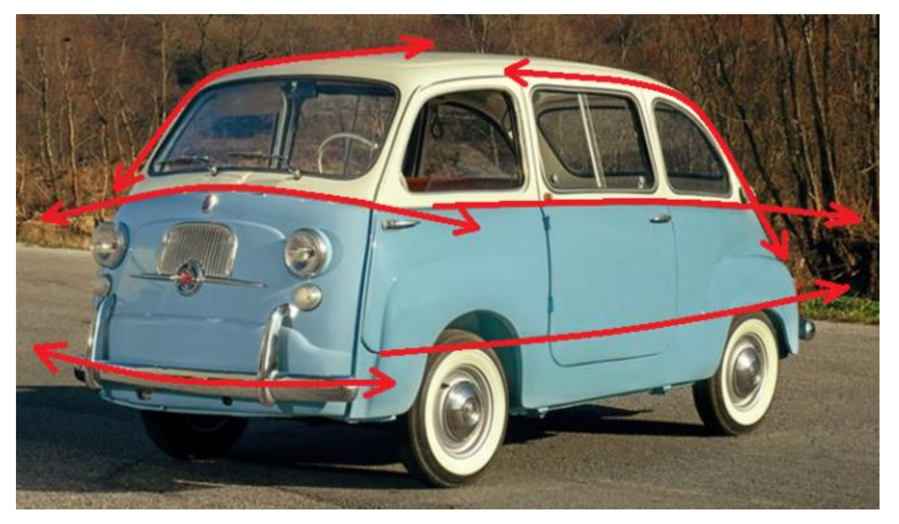
The aim of this work is the realization of an automotive design project for a new version of the Fiat 600 Multipla; the first version is from the year 1956 (
Figure 1 and
Figure 2). The reference segment (TARGET) was identified for the first time through a QFD analysis and a Benchmarking, and the car was considered to belong to the segment of city vehicles (4WD), low range, with four to five seats; a market segment in great demand and today covered, for example, by the SMART Four Four (
Figure 3 and
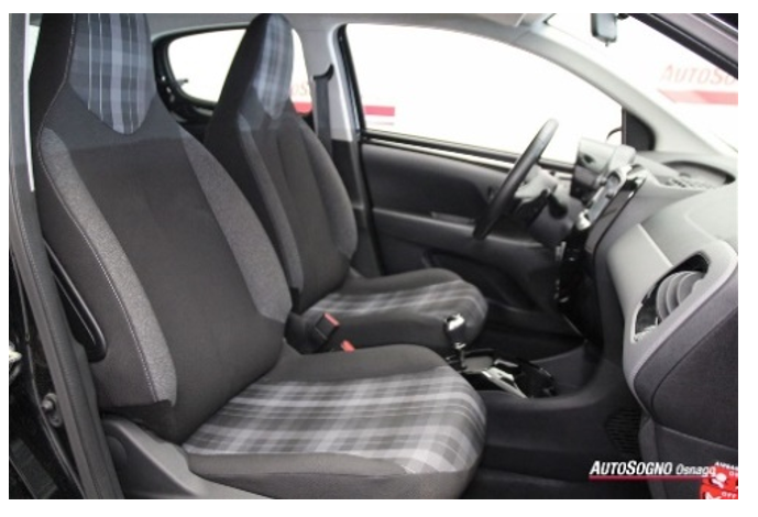
Figure 4) and the PEUGEOT 108 (
Figure 5 and
Figure 6).
2. Materials and Methods
2.1. QFD Analysis
The QFD (Quality Function Deployment) has as its objective the excellence in the quality of a product, in the broadest sense of the term, evaluated in terms of customer satisfaction; the QFD is implemented during the entire product development process, from market analysis, design, industrialization, to pre-production, and is recognized both scientifically and industrially as the most powerful decision support tool in the context of product innovation [
1].
The QFD uses calculation matrices, interviews and brainstorming sessions to improve the understanding of customers’ requests and needs, correlating them with the process of developing new products and with the characteristics that these products must have. However, the QFD is also a method for orienting the design towards the characteristics of the product that are most important for the customer. The QFD, therefore, uses objective mathematical methods and at the same time uses the subjectivity component present in the assessments of the working group and designers [
2].
At the end of its process, the QFD helps managers or members of a working group to make operational decisions and to adopt the necessary compromises by providing a complete, clear and solid methodological path involving all company functions and various organizational levels.
The first step through which the QFD develops is the six questions: they are able, through the choice and definition of the parameters that are identified through them, and can be discussed qualitatively, to guide the designer in his choices for the project of the new FIAT 600 Omega [
3].
- (1)
WHO: Who uses the machine? User, average motorist interested in a comfortable and versatile means of use; car sharing companies; also disabled users; the vehicle is not particularly addressed to car enthusiasts. Requirements obtained after the discussion: COMPACT—ECONOMIC–SAFE—SPACIOUS—CUSTOMIZABLE.
- (2)
WHAT: What do we need it for? It is used to transport people quickly and easily along urban routes, so it is not necessary for long journeys. Requirements obtained after the discussion: COMPACT—REACTIVE—FAST.
- (3)
WHERE: Where is it used? Inside cities and not on dirt roads. Requirements obtained after the discussion: COMPACT—REACTIVE—SCRATCH—ECOLOGICAL.
- (4)
WHEN: When is it used? It is thought to have frequent use, both day and night. In daily activities, at work and in leisure time. Requirements obtained after the discussion: SMART, SAFE, FAST.
- (5)
WHY: Why is it used? Because it is more convenient than using public transport. It is used as a very versatile and versatile means of movement. Easy to park and drive. Requirements obtained after the discussion: COMPACT, REACTIVE, ECONOMIC, SAFE, SPACIOUS, FAST.
- (6)
HOW: How is the means of transport used or how is it powered? We think of an electrical supply. How is the vehicle driven? Both manually and automatically. Requirements obtained after the discussion: SMART—AUTOMATED—ERGONOMIC.
The most relevant characteristics of the product must be further analyzed through the Interrelation Matrices (
Figure 7 and
Figure 8).
In particular, it is necessary to find the most important characteristics, through the Relative Importance Matrix (
Figure 8) and the most independent characteristics through the Dependence/Independence Matrix (
Figure 7). Green squares represents the most independent characteristics; grey squares instead are on the diagonal; here, it is not possible to insert values because each characteristic cannot be dependent or independent versus itself.
To build the Dependency/Independence Matrix, the main requirements that the product must have and which have been identified through the six QFD questions are reported in the rows and columns of a matrix. The cause and effect relationships between the various requirements are then determined, i.e., the dependency and independence relationships, considering as input each column element (CAUSE) and as output the corresponding element of the row (EFFECT). These relationships are then estimated through a scale of values equal to 0, 1, 3, and 9 (depending on whether the relationship is null, weak, medium or strong). To build the Matrix of Relative Importance, proceed as in the previous case, reporting in the rows and columns of a matrix the main requirements that the product must have and which have been identified through the six QFD questions. The relative importance (relative weight) of each requirement is then determined, with respect to each other, and based on it the values 0, 1, and 2 are attributed (depending on whether the row element has importance minor, same importance or major importance, of the element in the column). Ultimately, the most independent characteristics and those with higher relative importance will be the technical characteristics on which to focus for the development of a new car (they are the ones that have achieved the highest score within the matrix).
In this matrix, green squares represents the most important characteristics; grey squares instead are on the diagonal; here, it is possible to insert values because each characteristic can be important in the similar way versus itself.
The most independent characteristics obtained by “QFD Dependence/Independence Matrix” are to identify the new product to be:
COMPACT—REACTIVE—AUTOMATED—SAFE—CUSTOMIZABLE.
Whilst the most independent characteristics obtained by “QFD Relative Importance Matrix” are to identify the new product to be:
COMPACT—REACTIVE—AUTOMATED—ECOLOGICAL—SAFE—ERGONOMIC.
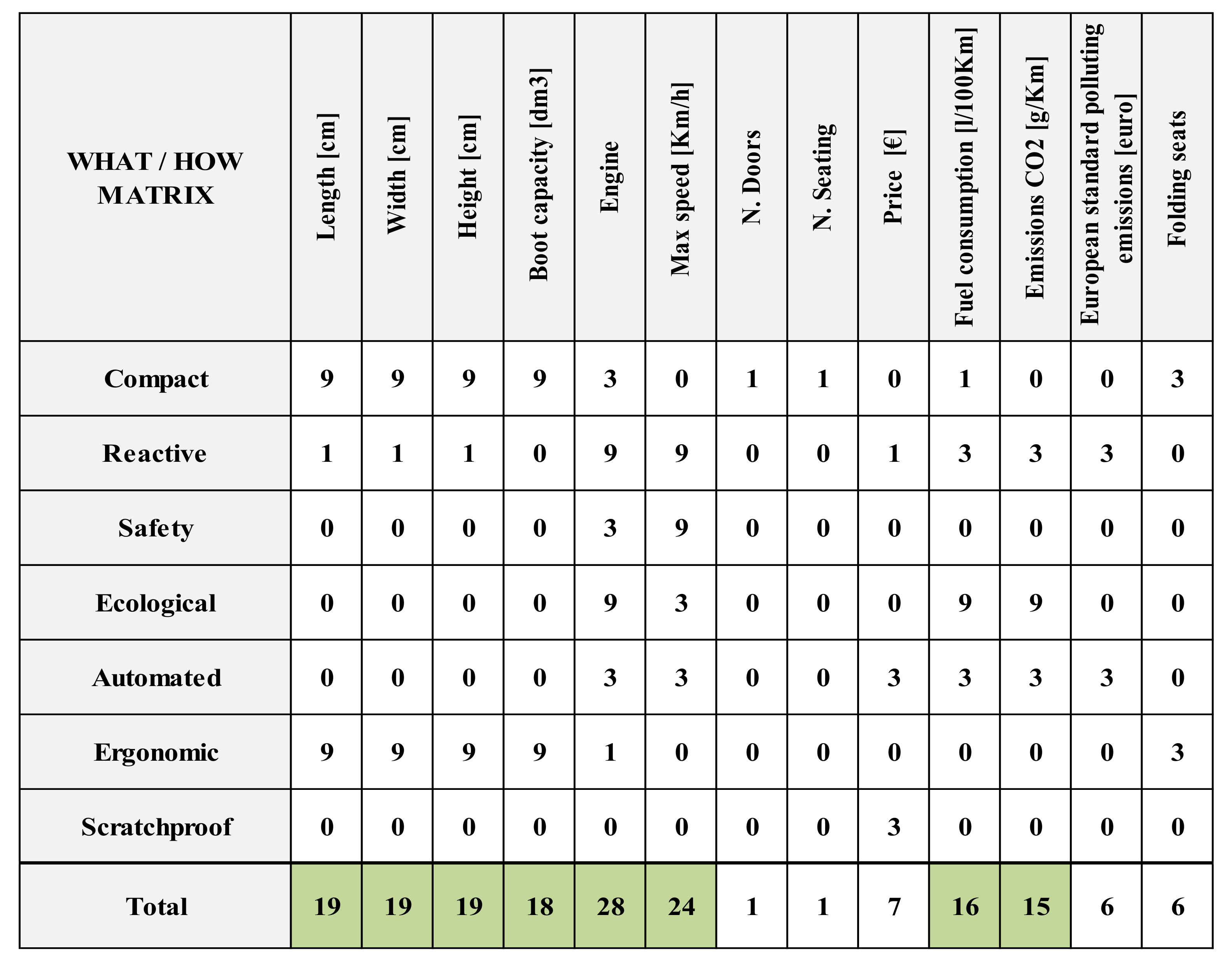
Through the analysis carried out by means of the interrelation matrices, it is possible to establish what are the technical requirements that must be developed in the product to be designed. However, it is also necessary to understand what are the technical actions to be taken to achieve these objectives. For this purpose, it is useful to use another matrix, the Relationship Matrix or the What/How Matrix (see
Figure 9). The sum of each column of the Report Matrix (What/How Matrix) indicates what is called the Technical Importance of the action within the design process; clearly the higher the score achieved, the greater its technical importance.
In addition to the study of the main characteristics to be taken into consideration in the design of the new FIAT 600 Omega, it is necessary to take into account market competition and to do this we will use Benchmarking and Top-Flop analysis. Green squares represents the most important technical characteristics referring to customer requirements.
2.2. Benchmarking and Top-Flop Analysis
In order to have a broader view of the current scenario, comparative analysis is essential to understand the surrounding market environment and to have a precise overview of the number of competitors, their characteristics, their strengths and weaknesses. For this analysis, many parameters have been taken into consideration to obtain a complete picture: from the size of the vehicle, to the luggage van, from performance, to consumption, from cost, to emissions. (
Figure 10).
Subsequently, we passed the Top-Flop analysis, calculating the resulting delta (Δ) for each vehicle. The absolute winners of this analysis turned out to be the Panda and the Up model, thanks to its different points in favor. According to the procedure, the values that we want to assign to our product must appear in the innovation column to the right of the graph and, in the end, the result must be greater than the best of the competitors [
4]. Δ is innovation index, i.e. TOP-FLOP = Δ. If Δ is high, we have an hi index of innovation that, in the future product, must be overcome.
2.3. SDE Stylistic Design Method
The study of this city car model is based on SDE = Stylistic Design Engineering, a design technique successfully used for a long time in the industrial field, in particular in the field of automotive design. SDE is based on a series of steps to be carried out in sequence and which leads the designer to obtain a product with the best possible characteristics and fully corresponding to the objectives of the project. The SDE methodology derives from the union of the work of the engineer Lorenzo Ramaciotti and the design company Pininfarina; now let us see the different steps of the SDE methodology [
5].
2.3.1. Stylistic Trends Analysis
The SDE methodology begins with an analysis of stylistic trends, which studies the company’s style trend throughout its history.
2.3.2. Sketches
After the analysis of the stylistic trends, the sketching phase follows, which is essential to put the first ideas and shapes of the product on paper, up to satisfactory sketches.
2.3.3. 2D Drawings (Orthogonal Tables)
Proceed with the 2D drawings of the best sketches, in order to better evaluate the dimensions and proportions of the individual parts and assemblies.
2.3.4. 3D CAD Models
Subsequently, the 3D models of the parts and assemblies are made on the basis of 2D drawings.
2.3.5. Rendering
3D models are rendered through appropriate software.
2.3.6. Solid Stylistic Model
At the end, we proceed with the creation of a solid stylistic model (normally called Maquette), which allows us to evaluate the lines and proportions of the model in a tangible way.
All the steps to follow of the SDE methodology are summarized in
Figure 11 [
6].
3. Case Study and Results: Application of the SDE to the New Model of the FIAT 600 Omega
The different phases of the methodology will be illustrated through the development of a new model of the FIAT 600 Omega.
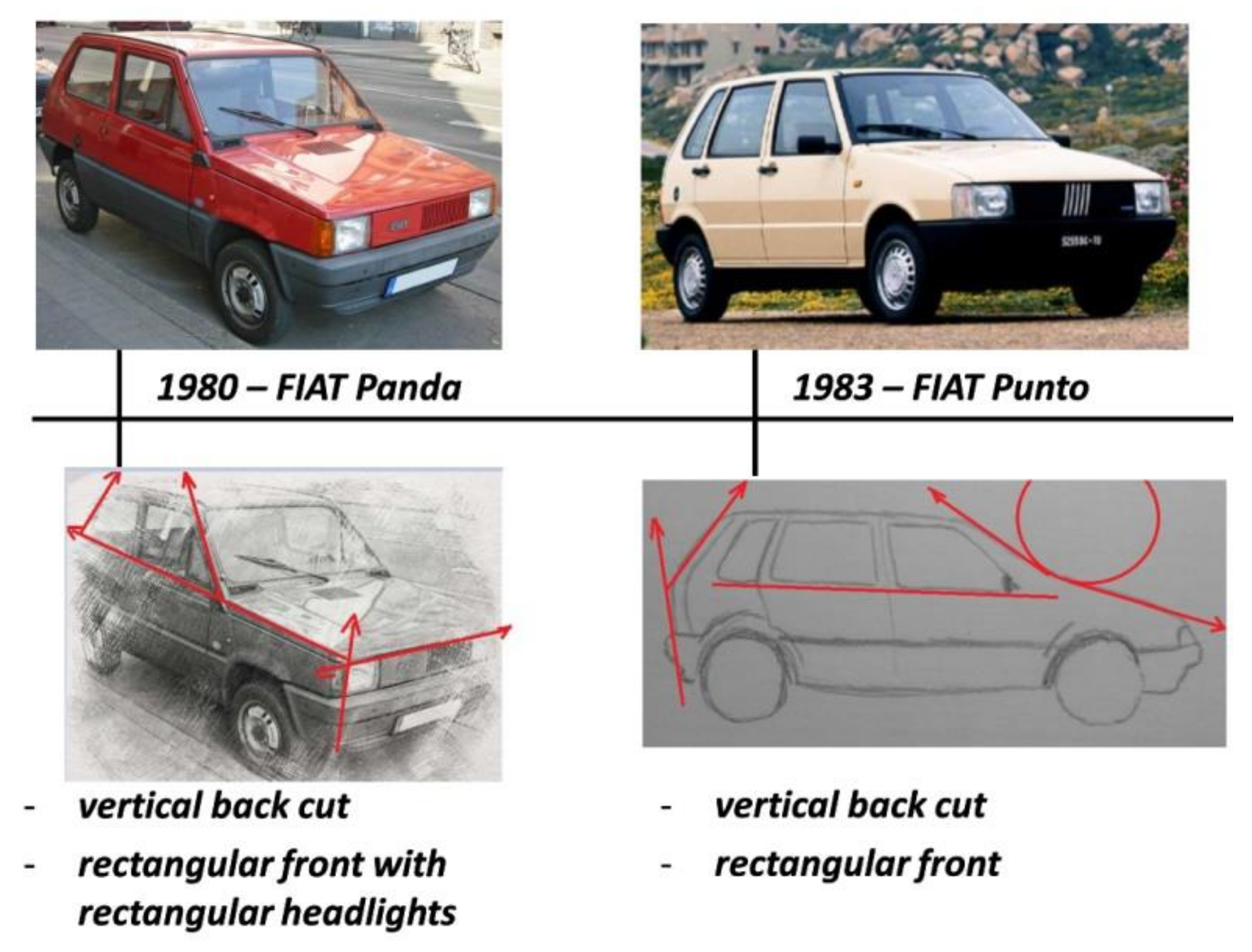
3.1. Stylistic Tendency Analisys
The work begins with the study of corporate stylistic trends. It is one of the most important phases of the whole process, because its bad or partial success will irreparably damage all the phases that will follow in the design process. The study is conducted taking into consideration the stylistic path of the car company of the model it intends to develop, the key moments both positive and negative and which act as a guiding thread in its evolution, and in general all the steps that have led to conceive your “corporate style” to the present day. In this first phase, the second phase of the study (that of the sketches) can be partially anticipated (
Figure 12). Red arrows are the styling lines, the ones that characterizes the new shapes.
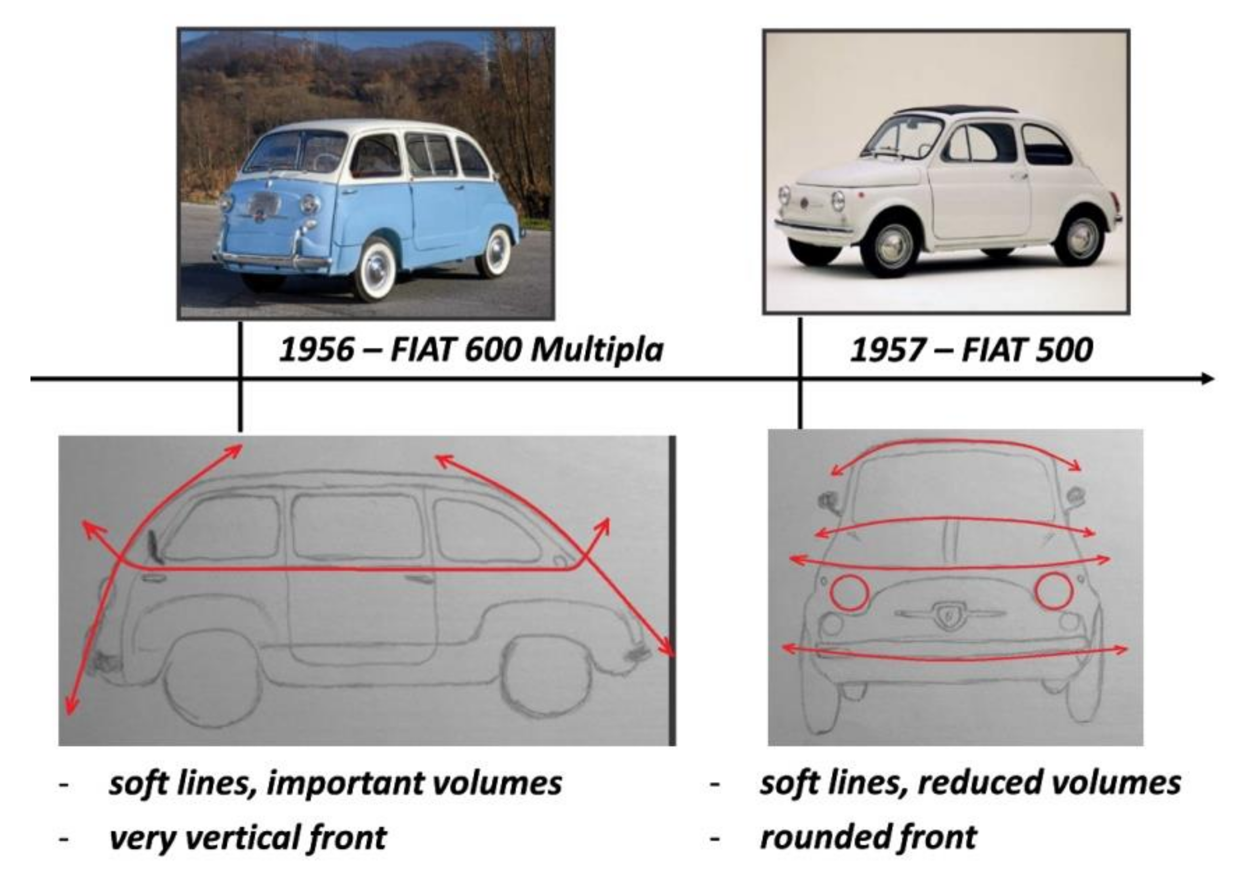
In fact, during the analysis of the style of the cars considered historic and most important for the car company, it is useful to redesign these models by making sketches with different views and paying particular attention to the lines and elements that made them significant. In
Figure 13,
Figure 14,
Figure 15 and
Figure 16, the stylistic evolution of FIAT car models was described and the most significant lines and features were highlighted.
3.2. Sketches
The purpose of this work phase is to provide new stylistic ideas for the product. It is precisely at this stage that the designer analyzes the type of stylistic trends to which customers turn. Today it is possible to say that the main stylistic trends can be summarized as:
Advanced Design
Natural Design
Stone Design
Retrò Design
Style trends can either remain separate or merge into a mix of different styles simultaneously present. An example of the different stylistic trends related to a common element, such as a glass bottle, is shown in
Figure 17.
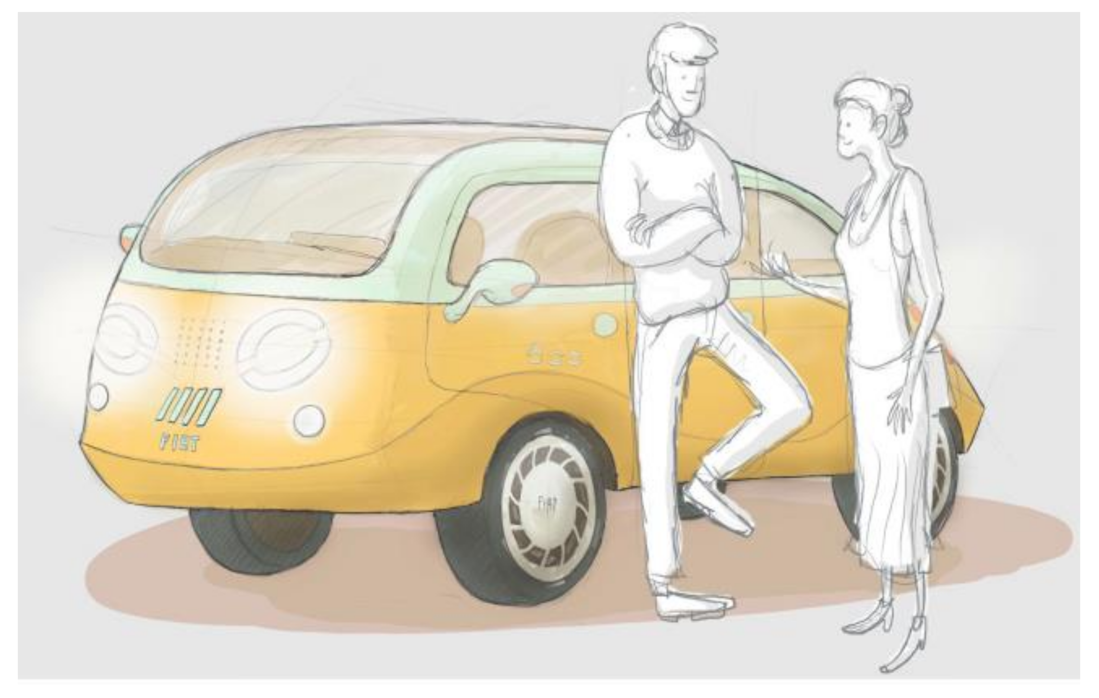
The sketches are drawings that indicate the creative aspect of the Design and do not care about the dimensional and technical aspect. The tools used in the sketches are sheets of paper and pencils (
Figure 22).
Various sketches are then made for each of the different stylistic proposals, Advanced, Natural, Stone, and Retrò, up to having a rather complete picture of the innovative product model (
Figure 23).
During this phase, the designer can also insert notes written with a pencil, or personal considerations within the sketches, to help him during the development of the project; these personal notes are visible in
Figure 18,
Figure 19,
Figure 20,
Figure 21,
Figure 22 and
Figure 23. The proposals considered less suitable for the model are discarded and only the sketches of a single model remain, which is modified and perfected until a stylistically coherent and satisfactory level is reached (
Figure 24).
3.3. 2D Drawings (Orthogonal Tables)
After selecting the sketch of greatest interest, it is time to turn it into a rigorous 2D computer drawing. This is a very important step because in freehand sketches the shapes often tend to be very “emotional” and obviously disproportionate. The 2D drawings (orthogonal tables), being very rigorous, make the lines much more realistic and allow you to control the proportions, in order to judge the model for what it really is. Consequently, compared to the sketches, the wheels will be smaller and narrower, the windows wider and in general the line less streamlined. In this way, being able to have a clear overview, it will be very easy to understand the possible weaknesses of the product and what the disproportionate elements are.
Appropriate changes are then made to the necessary areas and the 2D drawing is updated and meticulously observed again. This procedure continues several times (iterative process) until complete satisfaction in terms of lines, proportions and dimensions is achieved. When the 2D drawing, seen from all angles, is satisfactory, we begin to see the final appearance of the product and then move on to the next phase, 3D modeling [
7,
8,
9].
The tools used in 2D drawings are, for example, Autodesk’s Autocad software (
Figure 25).
3.4. 3D CAD Models
At this point, we move from 2D drawings to a 3D model of the project. Just as happens when sketches are transformed into 2D drawings, even in the transition from 2D drawings to the 3D model, the shapes of the model will not appear completely coincident with the lines of the 2D drawings. Then having completed the 3D model, the proportions will be evaluated from every possible point of view and from any dimensional and stylistic weaknesses.
Also in this case, therefore, the 3D model will undergo different transformations (iterative process), both to restore the right proportions, and to make clear the style concepts born in the sketch phase and that are often lost in the rigorous phases of 2D drawings. In this phase, the model is also detailed, with increasingly refined shapes: body side panels (
Figure 26), upper part of car body (
Figure 27), car roof (
Figure 28), complete car in its side and front view (
Figure 29), front rendering (
Figure 30), side and back rendering (
Figure 31).
The tools used in 3D CAD models are, for example, Dassault’s CATIA software, SIEMENS NX or Rhinoceros.
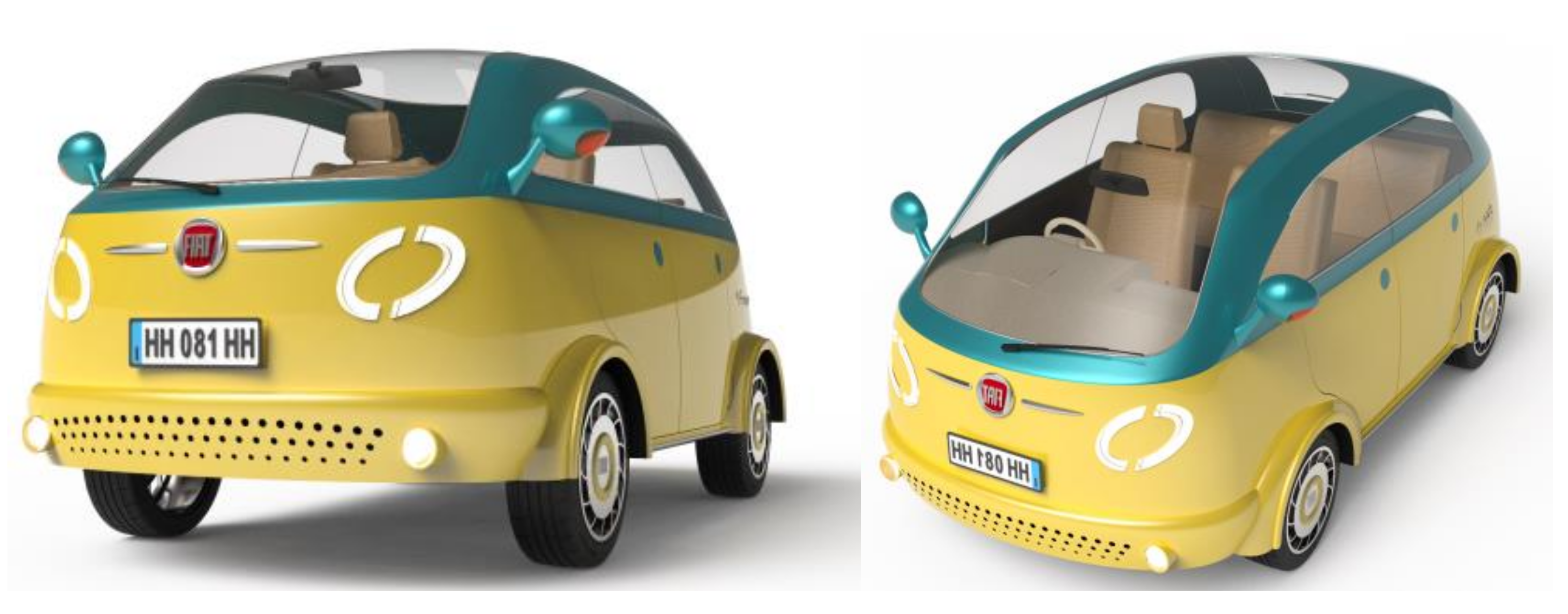
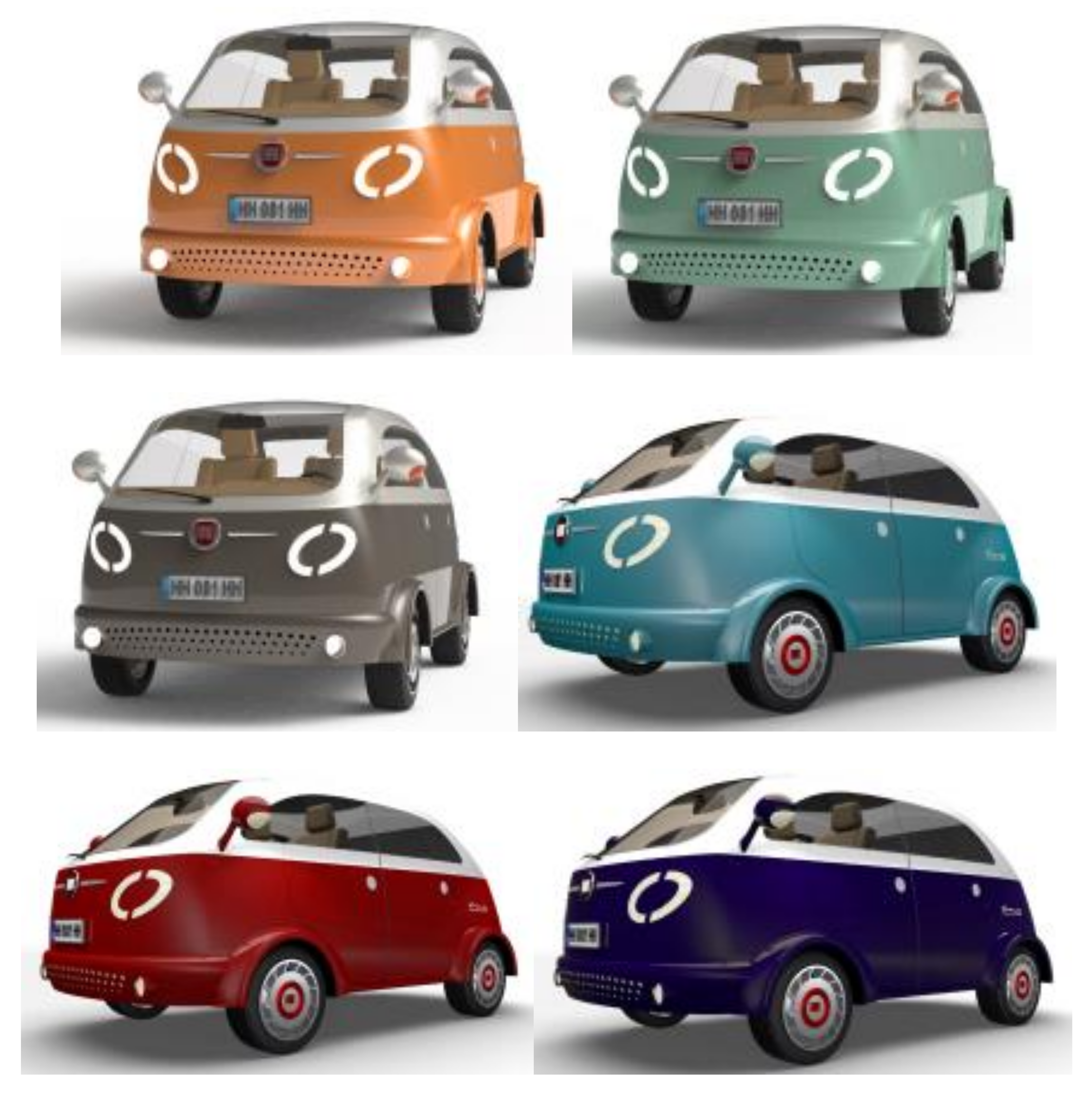
3.5. Rendering
At this point, the important communication phase takes place, that is the transmission of the coherence, organicity and beauty of the lines designed even to those who have not taken part in the project.
Rendering is the digital representation that simulates the material of the various components of the product, making the three-dimensional models realistic and also simulating the insertion of the new 3D model in one or more real environments; in this way, it is possible to make color choices and suitable color combinations, also taking into account the scenarios of use of the product in question (
Figure 32,
Figure 33,
Figure 34 and
Figure 35). The tools used in rendering are, for example, V-red, 3D Studio Max, Cinema 4D.
3.6. Solid Stylistic Model
Thanks to 3D modeling, it was possible to have a realistic shape of the project in a realistic digital environment. However, the display of the 3D model on the monitor has some limitations, such as the correct display and definition of the curvature of the surfaces and the always very difficult management of the proportions. It is necessary to create a physical model of the project, first in scale, then in reality (1:1 scale).
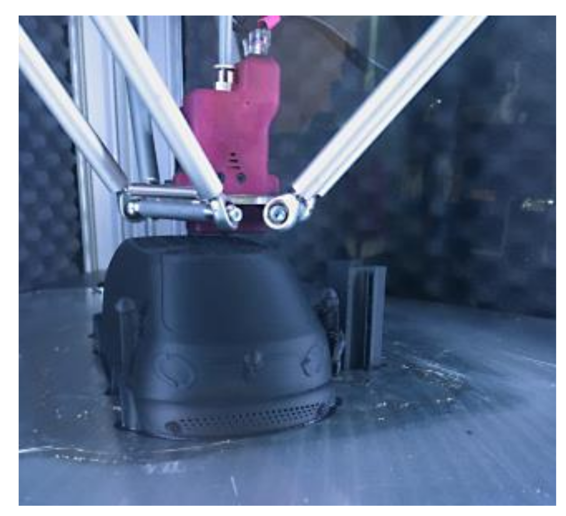
For the realization of the scale model in recent years, thanks to the growing diffusion of rapid prototyping, many technologies are available for designers, including 3D printing stands out in all its possible technological variations. Once the model is in hand, it is possible to confirm the goodness or not of the designed shapes and the modifications and corrections can be made until the desired shape is reached (
Figure 36). For example, the tool used in the solid stylistic model is 3D printing.
Once the final shapes of the product are obtained, it is possible to create a full-scale model (1:1 scale) of clay (synthetic clay), Ureol (epoxy resin), polyurethane or wood to evaluate the true shapes and proportions.
Thanks to the workability of the material, it is possible to make changes directly to the model on a real scale, even with complex geometries, and its effectiveness can be assessed immediately. These changes can then be scanned and imported directly into the 3D file, greatly speeding up the workflow and its effectiveness. At the end of this procedure, we are therefore certain that we have created a model with shapes and proportions consistent and in line with what we had imagined.
5. Conclusions
The stylistic design applications (SDE) were performed and a new concept car was obtained. SDE was able to do it, reaching the following objectives.
The analysis of the most convincing stylistic trends was carried out. In an innovative world in which style changes and evolves every day, it is important to monitor this process and then propose a new product following the current tendencies.
A new stylistic idea for a city car has been provided. In fact, many are the proposals of new city cars in the market: many are retro styled, others are advanced styled, others follow nature or robustness ad targets. In the present work, the authors identified the possibility to offer a new concept car styled following retro’ shapes.
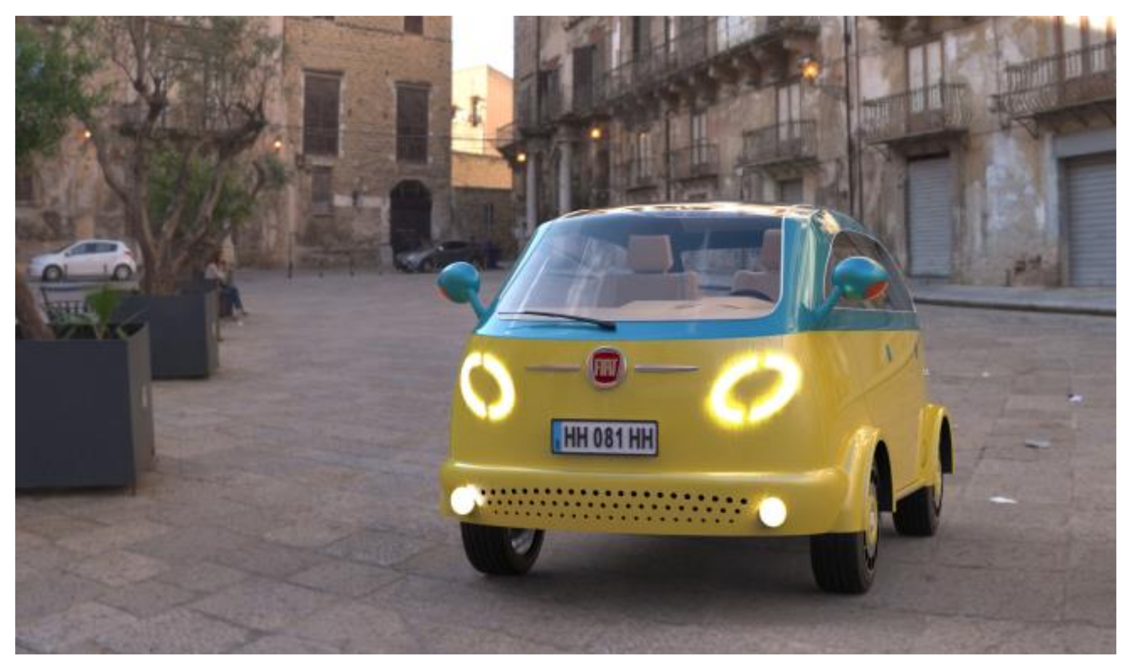
The other objective of SDE was to insert the new concept inside a real environment, realizing renderings and photo-insertions. Rendering and photo-insertions confirmed the goodness of the idea.
As a final result, a solid stylistic model (Maquette) was created. Stylistic Model (maquette) is the way to verify the new project. It is a sort of delivery.
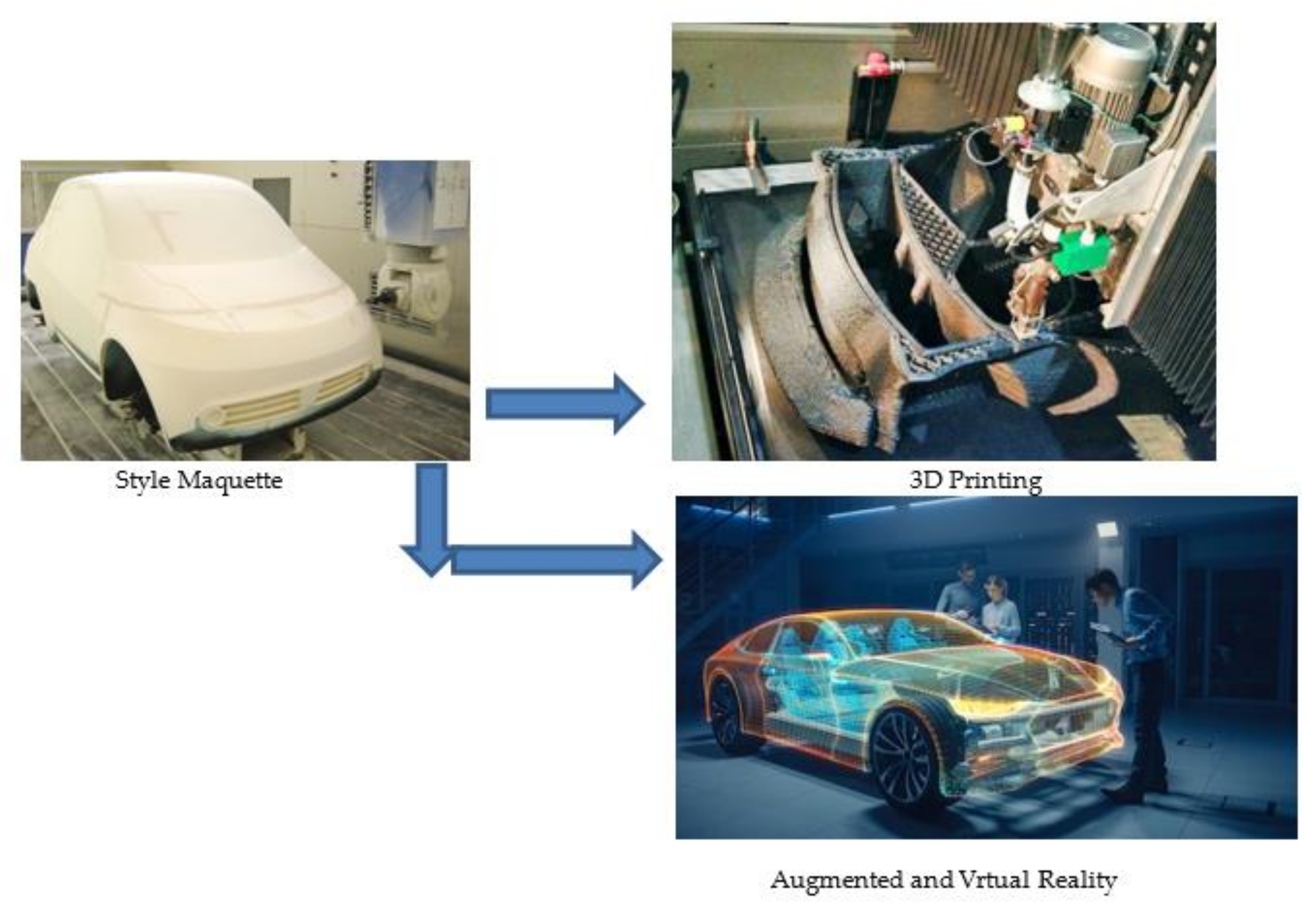
In addition, as seen in paragraph “4.Future Developments”, new development perspectives were provided for Stylistic Design Engineering (SDE). It means that all the SDE phases can be oriented to the implementation of the emerging technologies (derived from Industry 4.0) instead of the techniques nowadays used for SDE (
Figure 39).

 ,
, 


