1. Introduction
An ejector is a device, which could be integrated in different processes and applications to use energy efficiently. The use of ejectors in the industrial sector is not new. In the building sector, a growing interest is noticed through many studies integrating ejectors in heat pumping and refrigeration systems for higher efficiency [
1,
2]. The main advantage of the ejector is its simplicity (
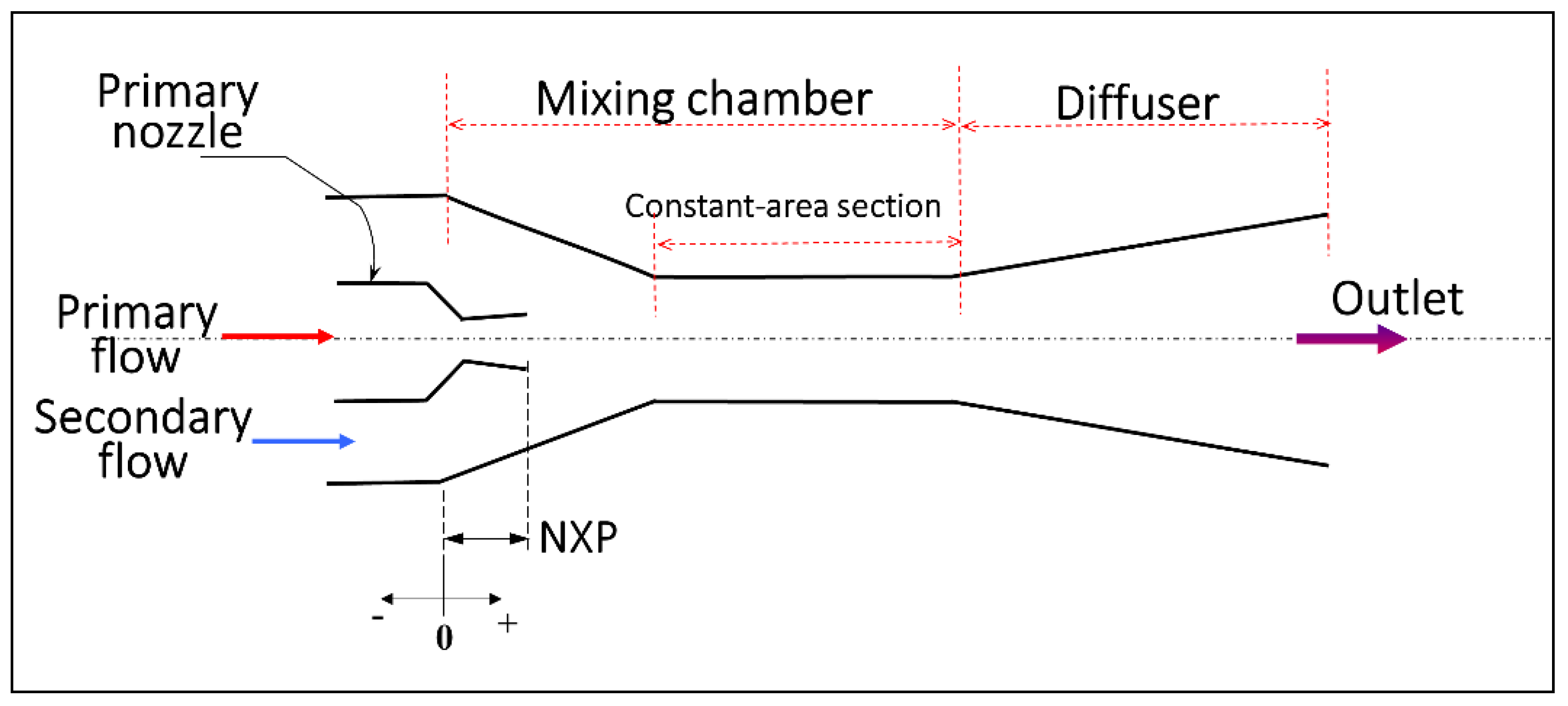
Figure 1). A high-pressure motive flow (primary flow) is used to draw and compress a low-pressure flow (secondary flow) to an intermediate pressure. The operation of the ejector is summarized as follows: the expansion of the primary flow in the nozzle creates a low-pressure area, which allows the entrainment of the secondary flow. The mixing of the two streams inside the mixing chamber may result in a first pressure increase. Finally, the diffuser slows down the mixture with increasing the pressure.
This study focuses on two-phase ejectors where a primary liquid stream drives a secondary vapor stream is considered. For cooling, refrigeration and heat pumping, two-phase ejectors offer good opportunities to build more efficient systems [
3]. Usually two-phase ejectors are used according to two approaches: ejector as an expander [
4] to recover the energy usually lost in the throttling valve, and generally applications with transcritical CO
2 present superior performance than other refrigerants. The second approach is ejector as a re-circulator [
5] to overfeed the evaporator, hence improving heat transfer.
The position of the motive nozzle with respect to the mixing chamber has an effect on the entrainment and the compression of the ejector, and thus the performance of the system. Generally, there is an optimal position, which maximizes the performance. The experiments of Liu et al. [
6] on a transcritical CO
2 ejector presented a maximum coefficient of performance (COP) for an air conditioner, when the nozzle was positioned before the mixing chamber at three times the diameter of the constant-area mixing section. In the case of the air-conditioning system with R410A of Hu et al. [
7], an optimal position of 3 mm before the constant-area section was found relative to the system capacity. The experiments of Ameur and Aidoun [
8] on two-phase ejector with R134a showed a maximum entrainment by positioning the primary nozzle at 7.6 mm before the constant-area section, and this position was not very sensitive to operational conditions. No optimal position for the nozzle was detected by the experiments of Wang and Yu [
9] with R600a two-phase ejector. Only a negligible increase of the entrainment could be observed by varying the nozzle position with respect to the mixing chamber. Around 6 mm the entrainment remained almost constant. Baek et al. [
10] performed a CFD study to investigate the effects of the geometry on the two-phase ejector entrainment performance with R134a. Among the examined parameters, the nozzle position located at 3 mm upstream of the mixing section generated the smallest recirculation zone for the flow at the nozzle outlet, providing the highest entrainment ratio.
Hu et al. [
7] varied experimentally the throat diameter (D
t = 0.9 − 1.2 mm) of a two-phase ejector in an air-conditioning system. The authors used R410A as refrigerant, and results showed that the case of D
t = 1 mm generated the best ejector efficiency and system performance. The authors also tested the possibility to adjust the throat diameter with a needle. Jeon et al. [
11], tested the effects of various D
t (1.04–1.21 mm) in the performance of an air conditioner using R410A with an ejector used as an expander. The experiments performed under various climatic conditions, generated results showing a maximum COP increase for the smallest diameter.
Typically, the area ratio defined in the literature as the ratio of the mixing chamber cross-sectional area to the nozzle throat area is an important geometric parameter. Sarkar [
12] showed by means of a thermodynamic analysis that for an ejector expansion refrigeration cycle, a maximum COP was obtained for an area ratio ranged from 5.7 to 10, depending on the refrigerants.
The open literature shows the importance of the mixing chamber geometry, length (L
m), and diameter (D
m), on the ejector performance. In general, for proper ejector operation, an optimization procedure might be essential to select these parameters. Indeed, a long chamber can result in considerable friction forces with a negative impact on the mechanism of pressure recovery, whereas a short one with small diameter may result in an inefficient mixing of the primary and secondary streams. Nakagawa et al. [
13] experimentally explored the effects of the mixing chamber geometry in the performance of a two-phase ejector with R12. Tested mixing ratio (L
m/D
m) ranged from 4 to 21. By increasing L
m and decreasing D
m, the results showed an enhancement of the pressure recovery, and beyond L
m/D
m = 16, no significant improvement was observed. Along the same lines of investigations, Banasiak et al. [
14] tested three mixing ratios (L
m/D
m = 5, 10 and 20) with transcritical CO
2 two-phase ejector. The ratio L
m/D
m = 10 was associated with the highest ejector efficiency.
Besides the importance of the mixing chamber, the geometry of the motive nozzle also has a significance impact on the ejector performance [
15]. The experimental study of Nakagawa et al. [
16] showed the effect of the angle of the primary nozzle divergent section, and its importance in the decompression boiling phenomena of transcritical CO
2.
According to experimental data found in the literature for water-steam flows, there is a strong correlation between the ratio L/D (nozzle length to the diameter) and the critical mass flow rate. A decrease was observed with increasing the length in the range L/D < 5 [
17]. However for (5 ≤ L/D ≤ 20), Sallet [
18] only reported a small effect for saturated and subcooled water. Choked flow in nozzles fed by liquid undergoes flashing, due mainly to rapid expansion pressure decrease [
19] and wall friction (formation, growth and departure of bubbles) [
20]. An interesting experimental study of Zhu and Elbel [
21] investigated the effects of nozzle convergent-divergent length on the initially flashing flow of R134a. Under the same nozzle inlet and outlet conditions, a long convergent part may present two different mass flow rates. According to the authors, this phenomenon may originate from the wall attachment and detachment of the two-phase flow. Results showed that the nozzle divergent length seems to be crucial in the choking flow. A long divergent part of the nozzle presented a choked flow with less mass flow rate than the shorter length. The effect of the inlet subcooling, also investigated in the range of 0–6 °C, showed that the choked mass flow rate tended to increase with the subcooling level. These last results confirm the trend observed previously by Ameur et al. [
22].
It may be inferred from literature overview that most two-phase studies relevant to ejectors available in the current literature focused on isolated nozzle flows of steam and water. The number of experimental studies regarding the geometry of nozzles working with conventional and new organic refrigerants are relatively limited. Furthermore, experimental data obtained under a large range of inlet subcooling conditions are scarce or unavailable. In addition, numerical studies in terms of CFD are not as prolific as for single-phase ejectors, due to more complex physics and lack of reliable data for validation. The main objective of the present study is therefore a contribution to fill this knowledge gap from an experimental perspective, in order to cover refrigeration and a range of potential industrial applications needs.
The performance of a two-phase ejector, under various working conditions, geometries and the nozzle exist position (NXP) values, was explored using R134a as the working fluid. Different primary nozzles were tested: with, without nozzle divergent, and with two different throat diameters. Tests with these geometries allowed to examine their impact on critical flow, on the ejector entrainment ratio for various nozzle position and under a large range of primary inlet subcooling.
2. Experimental Set-Up
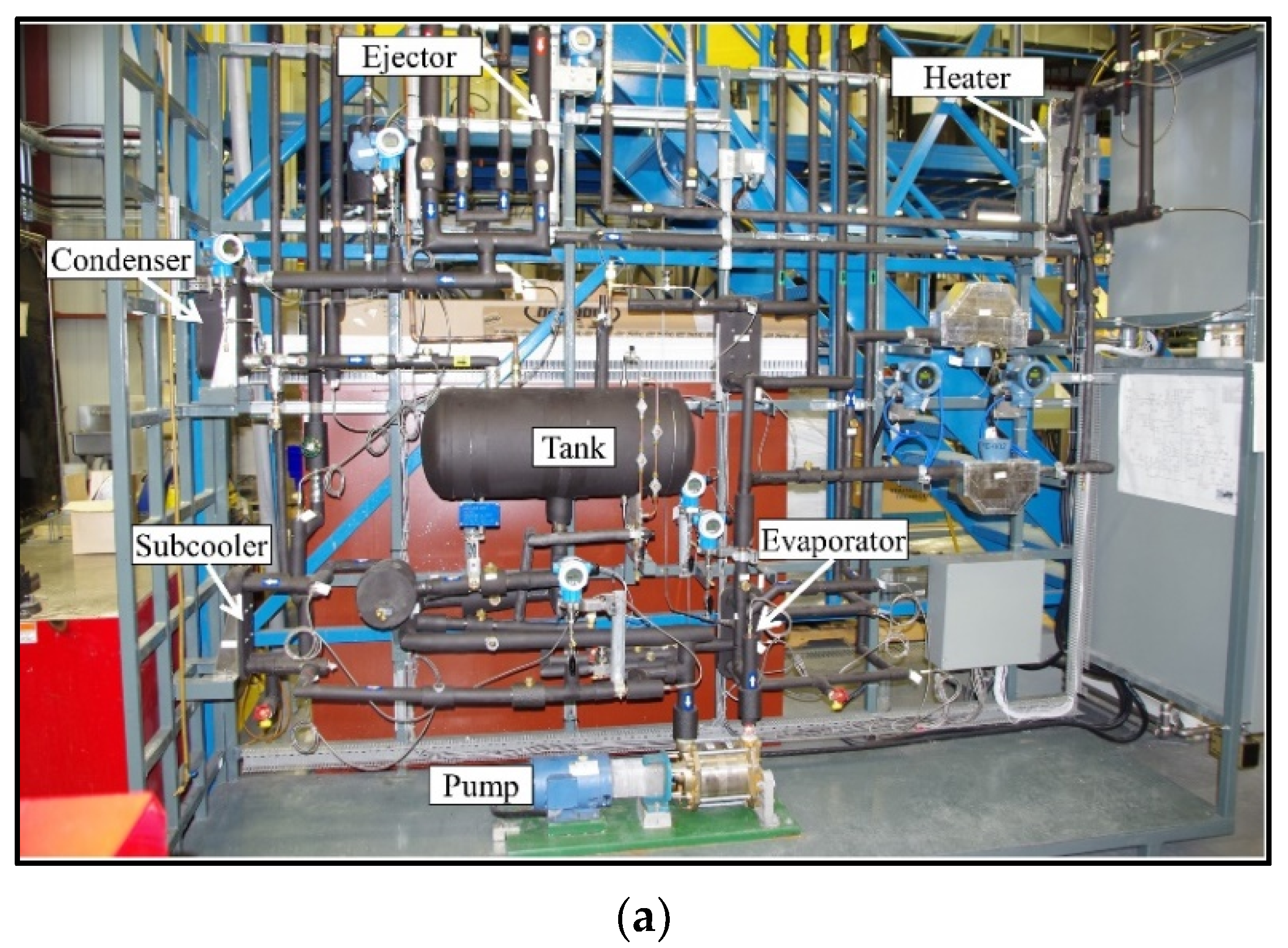
The experiments of this study were carried out at CanmetENERGY-Varennes (Varennes, QC, Canada) on an installation (
Figure 2a) designed to test two-phase ejectors using R134a as working fluid.
2.1. Description
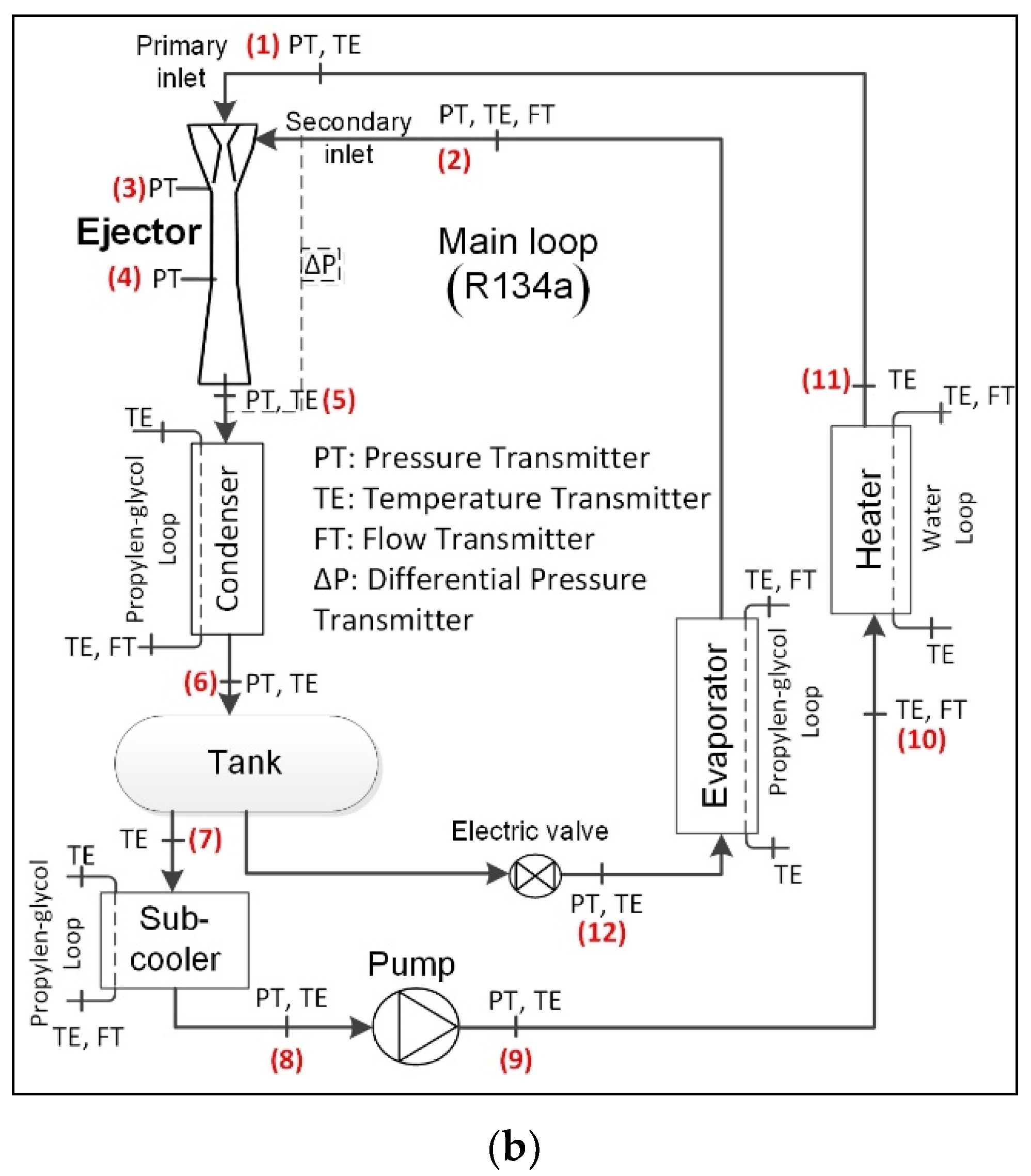
Figure 2b shows a schematic representation of the two-phase ejector test bench. The system consists of one main loop with refrigerant and four secondary loops (not represented) reproducing heat sources and sinks. The type of all heat exchangers are compact brazed plate. To simplify the diagram, accessories such as filter, sight-glass and hand valves are not represented on
Figure 2b.
The main loop is mainly composed of an ejector, a condenser, a tank, a sub-cooler, a pump, a heater, an electric valve, and an evaporator. The refrigerant pump is a multistage regenerative turbine pump (MTH L52B). A subcooler used to provide the required subcooling at the pump inlet to prevent pump cavitation. Propylene glycol circulates in secondary loops of the condenser, the subcooler and the evaporator. Heater loop is fed by water.
A 10 kW condensing unit with R507 refrigerant provides cooling to the condenser and the subcooler. It works in connection with the evaporator secondary loop to reduce operating time when working at low temperature level is required. Electrical heaters of 5 kW and 9 kW respectively used with the evaporator and heater auxiliary loops maintain appropriate temperature levels.
The operation of the test bench is summarized as follows. The pump feeds the primary entrance of the ejector with liquid refrigerant and the required pressure is imposed by means of a variable frequency drive. The heater upstream the ejector allows controlling the temperature at the primary inlet. Hence, subcooling of the primary stream is limited by controlling the water flow rate and temperature at the heater inlet entering. However close to saturation, fluctuations of the primary mass flow measurement are present.
The vapor-liquid mixture leaving the ejector flows through the condenser. Controlling the temperature and flow rate of the propylene glycol entering the condenser maintains the ejector outlet pressure at the required level. The liquid from the condenser collects in a tank. Part of it feeds the primary inlet, and the rest makes the secondary flow going through the expansion valve and the evaporator. For an accurate control, a step motor to obtain a small pressure difference between the tank and the evaporator operates the electric valve. The temperature and flow rate control of the propylene glycol entering the evaporator allows maintaining a given superheat at the secondary inlet, which ensures a stable measurement of the corresponding mass flow rate.
2.2. Measurements and Uncertainties
High quality measurement instruments (temperature, absolute and differential pressure, flow rate) are positioned as shown in
Figure 2b. RTD sensors, metallic membrane pressure transducers and Coriolis flow meters are used in the main loop. RTDs and magnetic flow meters are used in the auxiliary loops. Please note that the pressure sensor installed inside the ejector, immediately before the zone with constant-area (location 3 in
Figure 2b) made it possible to monitor roughly the nozzle pressure outlet, and the expansion of the secondary stream.
Table 1 summarizes the instrumentation types and measurements information. The operating pressures, temperatures and flow rates were recorded with calibrated instruments in the full range of operation. Additional uncertainties on the flow measurements apply when the temperature at the primary inlet of the ejector is very close to saturation.
The data recorded every three seconds was averaged at ten-minute intervals after reaching stable and steady state conditions. Energy balances carried out regularly on the evaporator and the heater were generally within less than 10% and 3% respectively. Several repeatability tests were also performed during the experiments.
Essentially, the entrainment ratio (Equation (1)) represented the main performance parameter of the ejector, in the results section. The entrainment ratio is defined as the ratio of the secondary mass flow rate (
) and the primary mass flow rate (
). This parameter measures the ejector capacity to draw the secondary fluid. Based on the recommended procedure [
23,
24], the uncertainty of the entrainment ratio expressed by Equation (1) was ±0.8%.
Finally, the quality of the data collected on the test bench was previously validated by comparison with the authors’ modeling, fully detailed in our publications [
22,
25].
2.3. Ejector and Nozzles
The ejector design relied on in-house modeling developments based on a thermodynamic approach as well as various critical models for the primary flow nozzle [
25,
26]. These tools and procedures also make use of information, parameters and data collected from the relevant scientific literature.
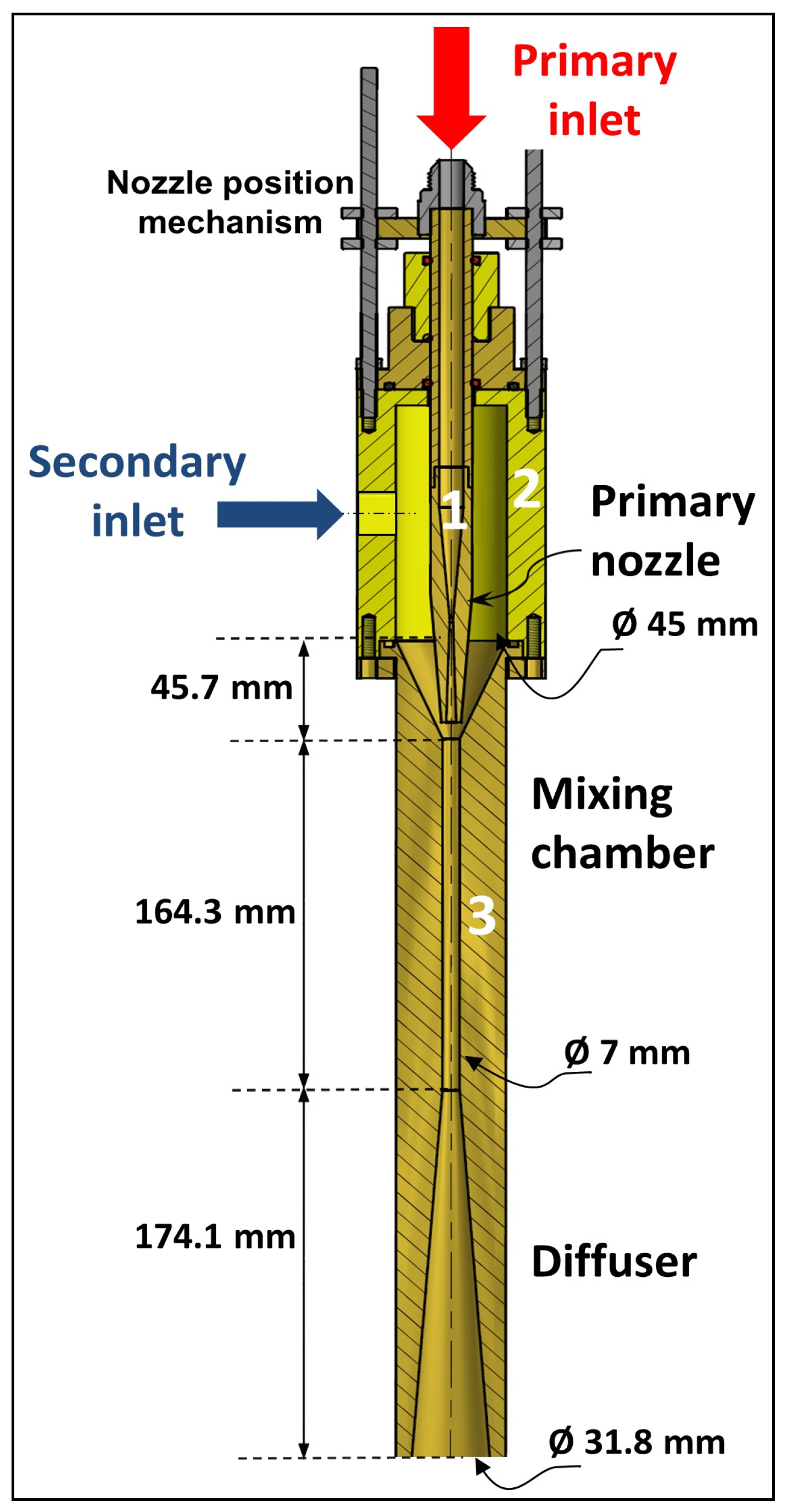
Figure 3 is a view of the ejector with its main internal parts and dimensions. The ejector is made of brass and presents three parts: (1) primary nozzle, (2) suction chamber and (3) mixing chamber-diffuser. The ejector is equipped with a movable system for the primary nozzle for NXP adjustments.
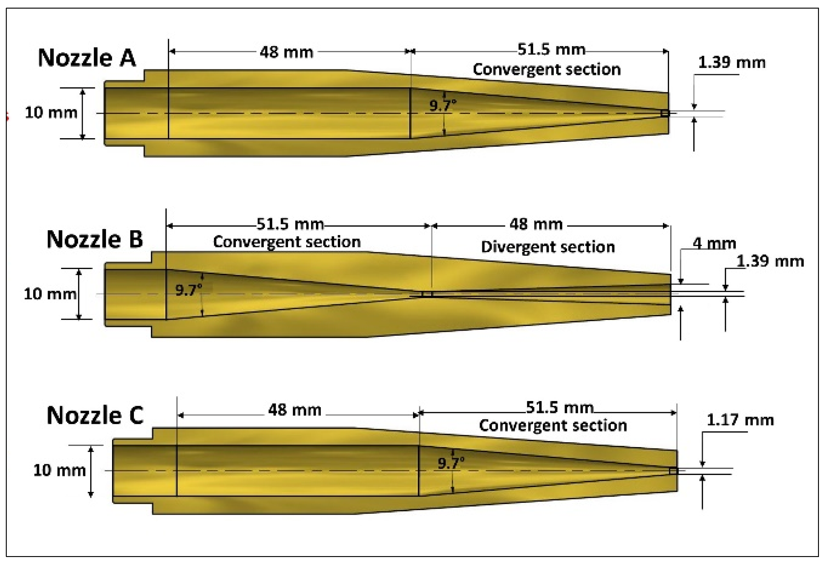
The same ejector body was used to test successively three nozzle geometries, represented in
Figure 4. The three nozzles have the same external shape and dimensions. Regarding the internal geometry, they present the same convergent section and different throat diameters; but only nozzle B has a divergent section.
Table 2 summarizes the main geometric dimensions of the three nozzles.
3. Results and Discussion
The experimental results on the operation and performance of a two-phase ejector with the refrigerant R134a are presented. Three different nozzles, with two throat diameters, with and without the divergent (see
Figure 4), were used to determine the impact of this geometry change on the ejector performance. The effect of the divergent was examined by comparing nozzle A to nozzle B, and regarding the effect of the throat diameter by comparing nozzle A to nozzle C.
Various positions of the primary nozzle inside the mixing chamber, and different conditions at the inlet and outlet of the ejector were tested.
The NXP was tested in the range of −10 mm to 44.4 mm. The definition of the NXP used in this paper relies on the sketch drawn in
Figure 1. Two pressures at the primary inlet were used (8.8 bar and 14.9 bar), and the pressure at the ejector outlet was varied in the range of 3–7 bar. To cover refrigeration and potential industrial applications, a large range of subcooling at the primary inlet (0.5–46 °C) was explored. Subcooling was evaluated with Equation (2), based on the temperature (
) and the pressure (
) measurements at the primary inlet. The saturation temperature (
) was calculated with the measured
and NIST-REFPROP database [
27].
During the tests, the entrainment was favored over the compression, thus the valve before the evaporator was kept almost completely open, resulting in a secondary pressure slightly lower than the outlet ejector pressure. Tests with induced flow were made with the superheat at the secondary inlet maintained around 10 °C.
3.1. Critical Flow and Nozzle Geometry
As a first result (
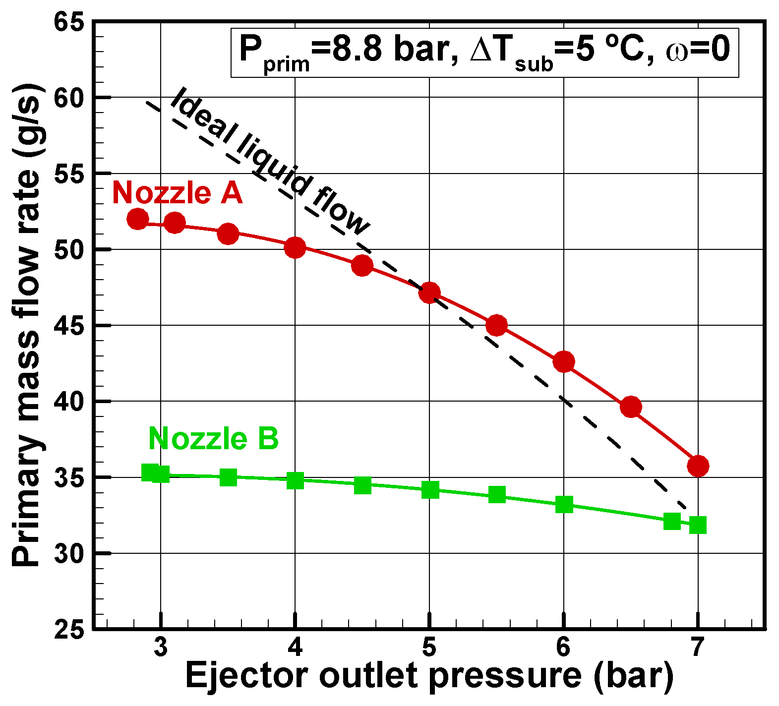
Figure 5 below), the entrainment of the ejector was not considered in order to see the effects of the nozzle’s divergent geometry on the critical mass flow rate. The conditions at the primary inlet for nozzles A and B were fixed to
= 8.8 bars and
= 5 °C, and the ejector outlet pressure was varied. To have a qualitative first feel of the difference between two-phase and single-phase flows in the nozzle, the ideal mass flow rate of a single-phase liquid was also plotted in
Figure 5. The ideal mass flow rate was theoretically evaluated by Bernoulli equation [
28]:
where ρ, A and ΔP represent the density, the cross-section area and the pressure difference between the nozzle inlet and outlet, respectively.
Figure 5 shows a typical trend of the primary mass flow rate with the outlet pressure: the flow rate increased with the decrease of the ejector outlet pressure. At low pressures, the mass flow rate became less sensitive to outlet pressure change. The curves of the two nozzles present different slopes. In the convergent-divergent case (nozzle B), the critical flow condition was reached with a relatively low flow expansion (P
ejector-outlet ≈ 4 bar), compared to the convergent case (P
ejector-outlet ≈ 3 bar). At high ejector outlet pressure (outlet pressure close to inlet condition), mass flow rate of nozzles (A and B) approximately converge toward an ideal single-phase liquid flow. A plausible interpretation may be that at high ejector outlet pressure, as the expansion becomes weaker, the flashing phenomenon will be difficult to initiate and the flow is single-phase [
21]. This should be even more the case for the convergent nozzle, which presents less friction and has a relatively higher pressure outlet due to the absence of the divergent. Thus, the ideal flow curve should be closer for the convergent nozzle. However, a probable explanation for this deviation is that the pressure at the ejector outlet is slightly higher than at the nozzle outlet, so the ideal curve should shift slightly to the right and come closer to the convergent nozzle A. The authors remind that the presentation of the ideal flow is used here only for qualitative purposes.
The nozzle divergent seems to favor the setting up of the critical conditions. A similar behavior was observed in the experiments of Zhu and Elbel [
21] and the results also showed that the divergent part of the nozzle contributes to the choking of initially subcooled flow. For significant subcooling, probably the divergent part will have the same trend to favor critical conditions. However, high subcooling inlet raises the critical mass flow rate, and the expansion required to reach this state increases as observed in a previous study [
22].
The nozzle length may also be considered to be another geometrical parameter that influences the critical flow [
17]. It is believed that the combined effects of the nozzle geometry and inlet conditions affect the critical conditions along the same mechanisms. Indeed, the critical conditions in nozzles are generally related to nucleation phenomena during flashing flow [
29], and their impacts on the position and the pressure of the flashing inception [
19]. The convergent nozzle with less wall length than the convergent-divergent nozzle generates less flashing vapor. Thus, the convergent nozzle appears to modify the establishment of the critical conditions in comparison to the convergent-divergent one, probably because it carries more liquid with less friction loss. This results in a higher expansion to reach the critical conditions. The results show that the converging nozzle reaches critical conditions with a pressure ratio (nozzle outlet/nozzle in) of about 0.34.
Please note that even with the same throat diameter, a high mass flow rate is associated with nozzle A with no divergent section (
Figure 5). At P
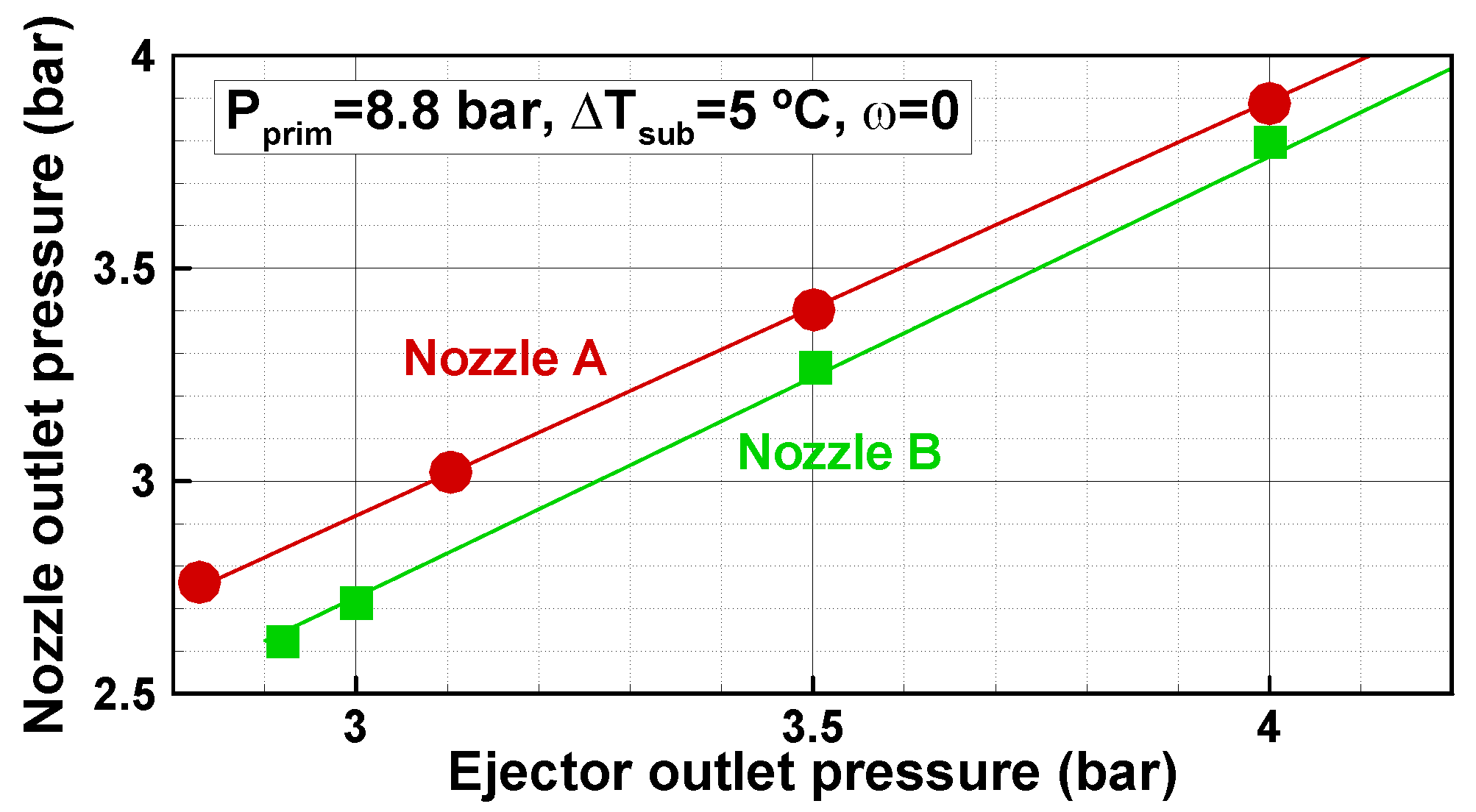
out ≈ 3 bars, critical mass flow rate was about 48.5% higher in comparison with nozzle B. This difference is perhaps due to the phenomena mentioned above and to the nozzle outlet pressure. Indeed,
Figure 6 shows that the flow in nozzle B expands more than in nozzle A. A higher pressure was measured at the outlet of nozzle A, probably helping to better withstand the pressure imposed at the ejector outlet. For the two nozzles, the same pressure sensor installed immediately before the constant-area section (location 3 in
Figure 2b) is used to measure the nozzle outlet pressure.
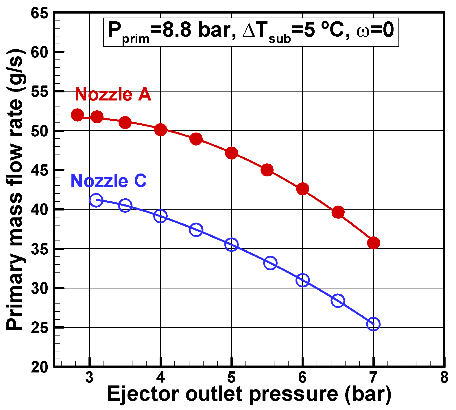
Nozzles A and C are compared in
Figure 7 to see the effects of the throat diameter on the critical mass flow rate. The conditions at the primary inlet are the same as used for
Figure 5. Obviously, nozzle A with a larger throat diameter presents a higher mass flow rate than nozzle C. Note the sensitivity of the geometry, an increase of the throat diameter about 18.8% resulted in a rise of the critical mass flow about 26.8%. The curves of the two nozzles (A, C) present the same slope, and seem to reach the critical flow condition at the same pressure. Under certain conditions, however, the test bench is limited in terms of pressure range. In fact, the ejector outlet pressure is directly related to the condenser pressure, which in turn depends on a secondary cooling loop. A condensing unit with R507 refrigerant provides cooling; unfortunately, the capacity of this unit is not sufficient at high ambient temperatures.
3.2. NXP and Nozzle Geometry
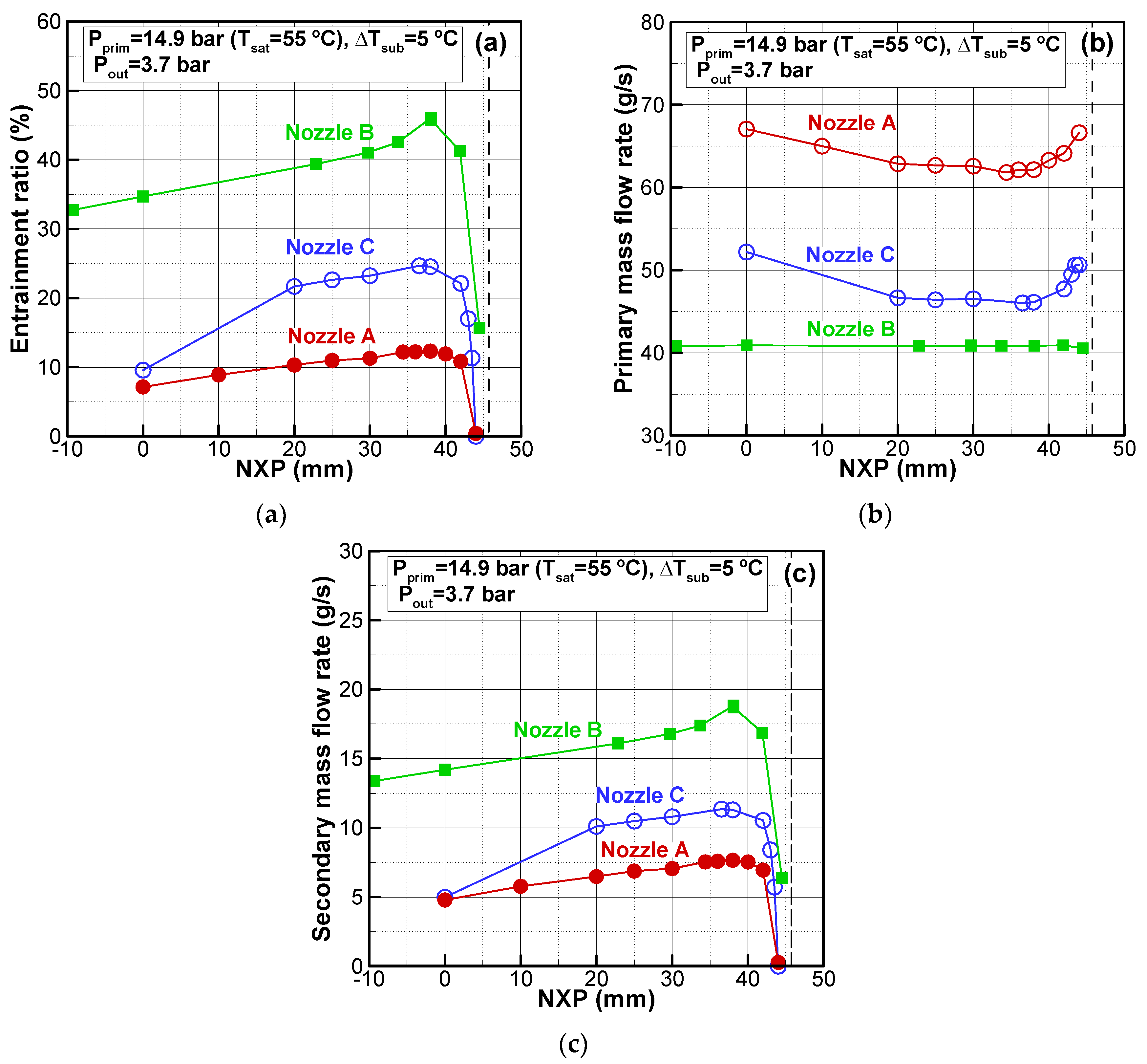
The effect of the nozzle displacement on the entrainment ratio, the primary and secondary mass flow rates for the three nozzle geometries is presented in
Figure 8. Primary conditions were fixed at P
prim = 14.9 bar, ΔT
sub = 5 °C, and the ejector outlet pressure was maintained constant at 3.7 bar. The opening of the electric valve upstream the evaporator was maintained constant, resulting in a secondary inlet pressure in the range of 3.65–3.8 bar. The position of the primary nozzle varied from −10 mm to 45 mm. The vertical dashed line in the figure represents the inlet to the mixing zone with constant-area.
For the three nozzles tested, the entrainment ratio has the same trend (
Figure 8a), increasing with the NXP until an optimal position, where the curve presents a maximum. Beyond this position, a sharp decrease of the entrainment occurs. By moving the nozzle downstream, and close to the constant-area section’s inlet, the passageway of the secondary stream flow increasingly reduces. This behavior was numerically shown in a CFD study by Baek et al. [
10]: for a two-phase ejector run with R134a, the nozzle displacement directly impacted recirculation in the zone developing between the primary and secondary streams immediately after the primary nozzle. The authors found there was an optimal position, which minimized the negative effects of the recirculation zone, creating a favorable pressure gradient across the suction chamber.
The internal geometry of the nozzles has apparently little effect on the optimal NXP, which approximately remains at about the same position (NXPopt ≈ 38 mm) for the three nozzles. For all tested NXP cases, Nozzle B presents the highest entrainment ratio.
Regarding the effects of the divergent section, at NXP
opt nozzle B (with convergent-divergent sections) reached an entrainment ratio close to 0.45; this value decreases by 74% in the case of nozzle A with no divergent section. The entrainment ratio of nozzle A is double penalized with a higher primary mass flow rate (
Figure 8b) and a lower secondary mass flow rate (
Figure 8c) than observed in nozzle B.
The primary nozzle divergent may affect in many ways the expansion level, the flashing mechanism, the jet’s shape, and the local flow around the nozzle outlet. As a result, explaining the suction mechanism of the secondary flow and the effect of the primary nozzle divergent may be tricky without the details of the internal flow structure. In an experimental study with CO
2, Berana et al. [
30] observed a strong link between the primary nozzle divergent length and the complex structure of the flow in the ejector mixing zone, downstream the nozzle. Later, Zhu et al. [
31] observed in their ejector flow visualization experiments on CO
2 that the entrainment ratio was inversely proportional to the angle of the expansion nozzle jet.
At the optimal position (
Figure 8a) by reducing the throat diameter from 1.39 mm (nozzle A) to 1.17 mm (nozzle C), the value of the entrainment ratio doubled due to a lower primary mass flow rate (
Figure 8b) and a higher secondary mass flow rate (
Figure 8c). Please note that while the motive flow reduced by 25%, the induced flow increased by about 53%. Probably in this case the primary stream occupied less volume at the inlet of the mixing chamber, thus allowing for more secondary flow to be drawn. Wang and Yu [
9] showed the same trend experimentally with a two-phase ejector operating on R600a. Various nozzle throat diameters were tested (0.6–1.6 mm), under different operation pressures. The entrainment ratio increased with decreasing throat diameters as the primary mass flow rate reduced appreciably although in this case the secondary mass flow rate decrease was very modest.
All the subsequent experiments were performed with the nozzles positioned at the optimal NXP identified previously.
3.3. Primary Flow Subcooling and Nozzle Geometry
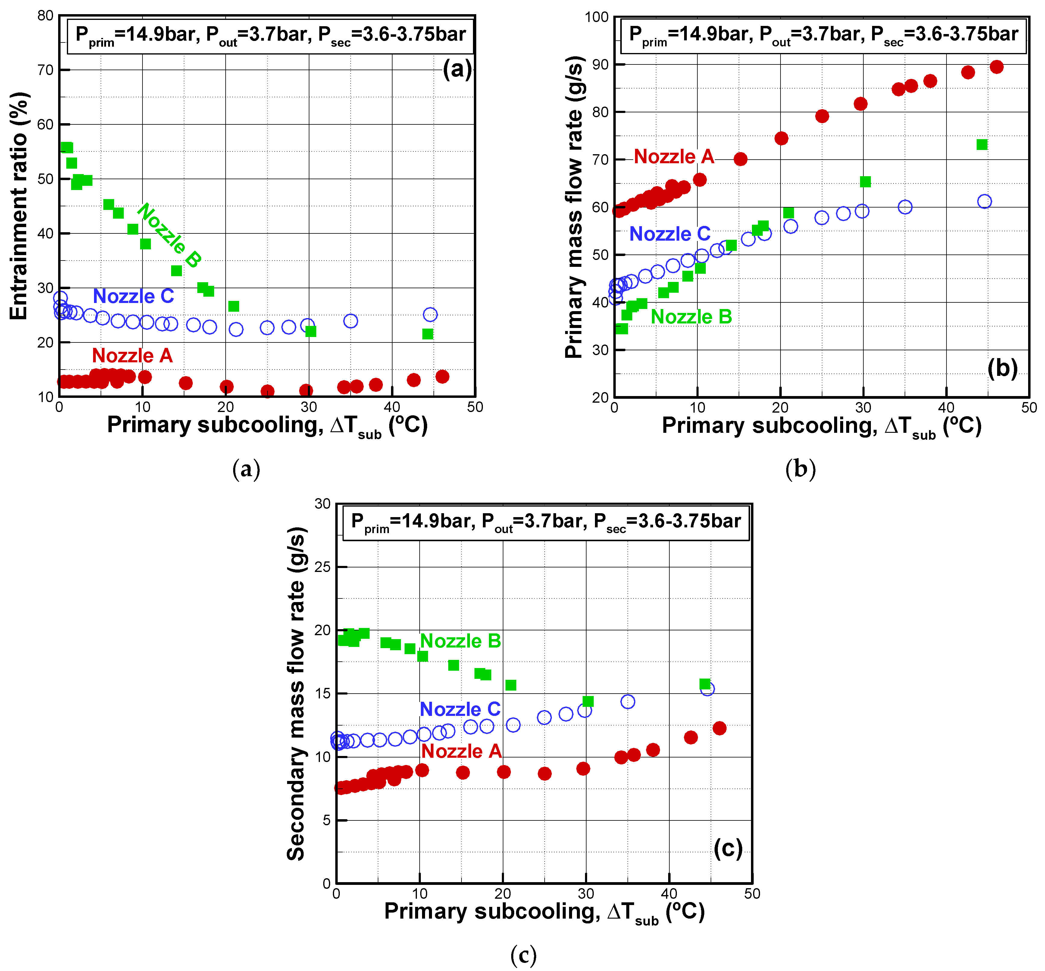
Effects of primary inlet subcooling on the entrainment ratio and mass flow rates for the three nozzle geometries are reported in
Figure 9. Subcooling ranged from 0.5 to 46 °C, the pressure at the primary inlet was set at 14.9 bar and the ejector outlet pressure maintained at 3.7 bar.
The level of the primary subcooling affects the entrainment ratio through both primary and secondary mass flow rates. However, this effect will depend on the geometry of the nozzle.
The primary subcooling level affects quite differently the performance of the ejector with the nozzle with or without the divergent portion. The ejector with nozzle B provided a higher entrainment ratio (
Figure 9a) with respect to nozzle A and greatly depended on the primary subcooling level. When the subcooling increased, the entrainment decreased and around ΔT
sub = 30 °C it remained almost constant. The entrainment ratio with nozzle A (without divergent section) was less sensitive to the subcooling level. For both nozzles (A, B) the primary mass flow rate (
Figure 9b) increased with subcooling at the primary inlet. The highest primary mass flow rate was recorded with the nozzle A. The ejector with convergent-divergent nozzle B provided a higher entrainment capacity of secondary flow than nozzle A (
Figure 9c). It may be noted in addition that the two nozzles showed an opposite trend in terms of subcooling at the primary inlet. With Nozzle B a decrease of the secondary mass flow rate was observed when subcooling increased up to ΔT
sub = 20 °C beyond which limit it became nearly constant. On the other hand, Nozzle A showed an increase of the secondary mass flow rate with subcooling, except for ΔT
sub = 10–30 °C where the entrainment remained almost constant.
The primary subcooling level affects in a similar way the performance of the ejector with different throat diameters. Curves of nozzles A and C (
Figure 9) present the same trend and slopes for the entrainment ratio and the mass flows. Nozzles A and C present an entrainment ratio almost insensitive to the level of subcooling at the primary inlet. The primary and secondary mass flow rates increase with the level of the subcooling in a proportional way, resulting in an almost constant entrainment ratio. Regarding the effects of the throat diameter on the entrainment ratio, previous results confirm that the ejector with the smaller nozzle throat diameter presents a higher entrainment ratio due to a favorable trend of primary and secondary mass flow rates. The ejector with nozzle C entrains more with less motive flow than nozzle A.
As stated previously, explaining the impact of the subcooling on the primary and secondary mass flow rates for different nozzle geometries can be tricky without a complete picture inside the ejector.
The results showed that regardless of the primary nozzle geometry, the primary mass flow rate increases with the level of subcooling. The increase of the mass flow rate with subcooling is more likely due to the density variation [
32], which is thought to prevail on other effects such as those of viscosity, for example. Another important parameter that affects the mass flow rate is the flashing inception, which depends on the available pressure drop in the subcooled liquid (pressure difference between inlet pressure and saturation pressure corresponding to the inlet temperature). Usually the liquid phase accelerates in the nozzle convergent; a flashing inception occurs very close to the nozzle throat [
19]. When inlet subcooling decreases, the subcooled liquid pressure drop decreases and the flashing point may occur earlier and move closer toward the inlet [
33,
34], which reduces the mass flow rate.
The results show as well that the level of the primary subcooling inlet affects the entrained secondary flow rate differently whether the nozzle presents a divergent section or not.
For a convergent-divergent nozzle, the secondary mass flow rate globally decreases with increasing the subcooling, and this trend was confirmed in a previous paper for a large span of operating conditions [
35]. For the convergent nozzle, the opposite trend is observed and the secondary mass flow rate increases with the subcooling level.
Unfortunately, as stated many times, without the details of the internal flow structure, explaining the complex suction mechanism of the secondary flow and the combined effects of the subcooling and the geometry nozzle may be somewhat approximate.
Subcooling and nozzle geometry may affect in many ways the expansion level, the flashing mechanism, the jet’s shape, and the local flow around the nozzle outlet. Obviously, the combination of all these phenomena could have an impact, directly or indirectly, on the suction of the secondary flow. The experiments of Zhu and Elbel [
21] on R134a nozzle, clearly show the impact of the operating conditions on the shape and the nature of the jet at the outlet of the nozzle.
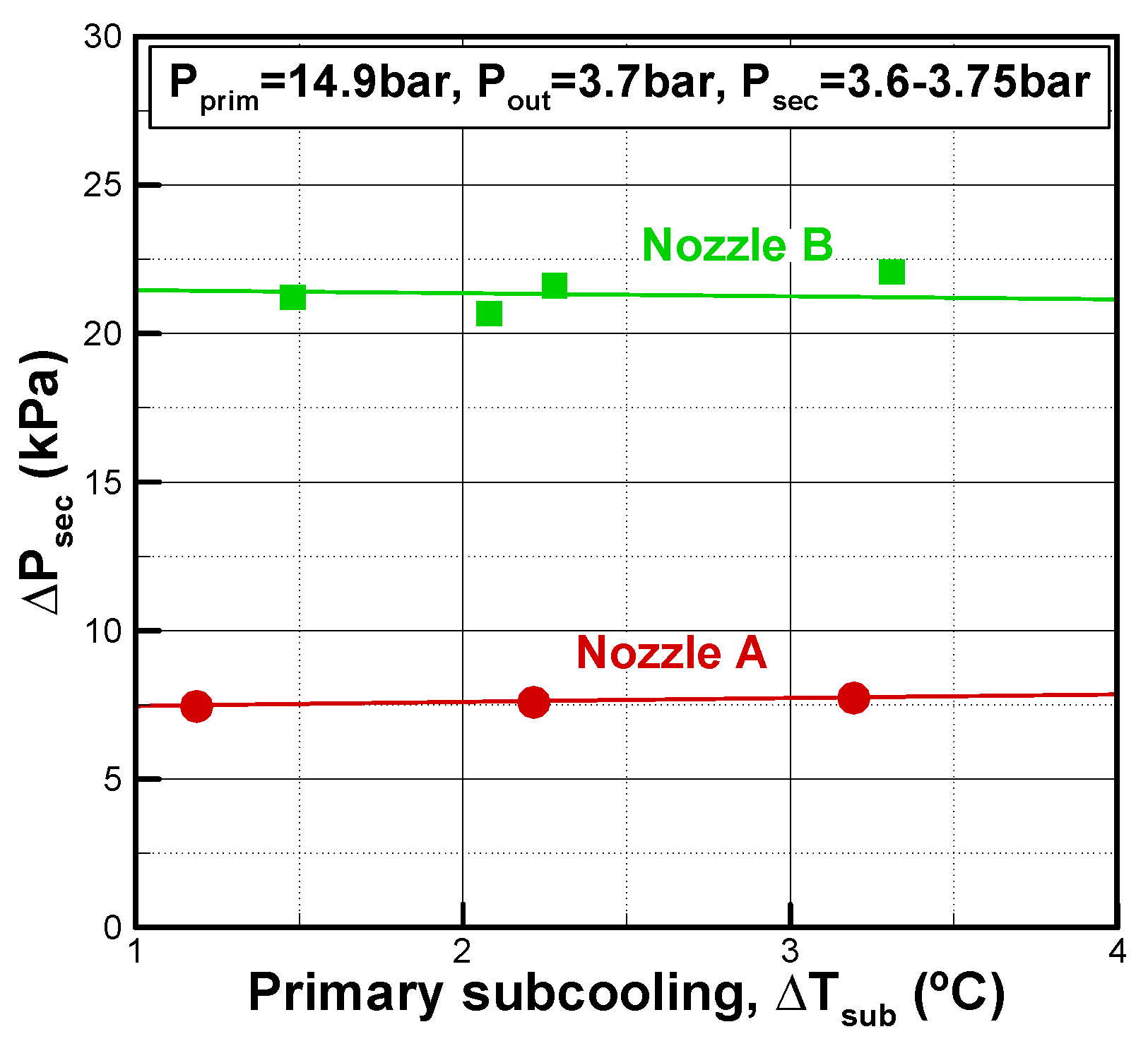
Among the factors that influence the entrainment ratio is the level of expansion in the nozzle. The availability of the pressure close to the nozzle outlet (P
3) and the pressure at the secondary inlet (P
sec), allows for the evaluation of the secondary pressure difference defined as:
Figure 10 shows this parameter relatively to conditions of
Figure 9 for subcooling between 1 °C and 4 °C. The expansion of the secondary flow of ejector with nozzle B is about 2.8 times higher than nozzle A. This difference probably partly explains the higher secondary mass flow rate drawn by nozzle B.


