Article

A Rolling Electrical Generator Design and Model for Ocean Wave Energy Conversion

by
Praveen Damacharla
1,* and
Ali Jamali Fard
2
1
R&D Department, KineticAI Inc., Crown Point, IN 46307, USA
2
Electrical Engineering, Amirkabir University of Technology, Tehran 1591634311, Iran
*
Author to whom correspondence should be addressed.
Inventions 2020, 5(1), 3; https://doi.org/10.3390/inventions5010003
Submission received: 12 November 2019 / Revised: 6 January 2020 / Accepted: 6 January 2020 / Published: 10 January 2020
(This article belongs to the Special Issue New Advances and Challenges in Wind Energy Extraction)

Abstract

:
Wave and tidal energies are some of the most prominent potential sources of renewable energy. Presently, these energy sources are not being utilized to their maximum extent. In this paper, we present a new conversion mechanism with an innovative electrical energy converter design that enables the use of wave energy to its maximum potential. The conventional wave energy converter comprises two stages of conversion (kinetic to mechanical and mechanical to electrical), imposing transformation loss that reduces the overall system efficiency. Additionally, the architecture and operational norms are dependent on the availability of shoreline areas, and the convertor is not suitable for all ocean weather conditions. To solve these problems, we have developed a wave energy conversion system that integrates the two stages of power with the minimum number of moving parts. This results in significant reduction of transformation losses that otherwise occur in the process. This paper presents an innovative idea of designing a DC generator that reduces the hierarchy of power conversion levels involved to improve the efficiency. The back and forth motion of the machine means it operates in a two-quadrant generation mode. The machine was constructed as a square box model with windings placed on both the top and bottom stator plates, and the rotor consisted of a field winding placed between these plates with two axes of operation. The electromagnetic field (EMF) induced in the stator plates is due to the resulting flux cutting, which is generated by a rolling object (rotor) in between them. A finite element analysis (FEA) of the machine is also listed to validate the flux linkage and operational efficiency. Additionally, a generator is fabricated to the predetermined design criteria as a proof of concept and the corresponding results are posted in the paper. Additionally, we present the material and cost limitations of this invention and outline some possible future directions.

Graphical Abstract

1. Introduction

With the increasing concerns related to energy demand and environment problems, wave power generation is gaining more traction than ever [1,2]. Ocean waves are one of the potential renewable energy resources available, with an estimated energy to be 17,500 TWh/year worldwide [2]. The estimates indicate that the annual wave energy potential of the U.S. coastline alone is around 2640 TWh/year [3]. The theoretical potential for a coastline works out to be approximately 60,000 MW, and it is possible to harness 40 MW of power per km of coastline in a low wave region (for example, one meter in height). As for high waves (5 m height), the power potential increases to as much as 1000 MW per km. According to the world wave energy chart released by World Energy Council, the Bay of Bengal and the Arabian ocean have a combined potential of 800 TWh/year per meter, and the Indian Ocean has a potential of nearly 1340 TWh/year [2,3].
There are many methods and designs employed to harness wave energy worldwide. The TAPCHAN [2] wave energy converter and the Islay wave energy converter are two of the few successfully working models, and are of the oscillating water column (OWC) type. On the other hand, the Duck, Clam, and Pelamis converters from the United Kingdom are of the floating type [2]. The Pelamis converter is one of the working prototypes, with a capacity of 750 KW, 150 m in length, 3.5 m in diameter, and composed of five modular sectors [2].
Many of the existing models follow a two-stage power conversion topology to generate electric power (stage 1: kinetic to rotational; stage 2: rotational to electrical) [4,5]. As this WEC topology has the drawbacks of low speed and poor stability, a gearbox could be utilized to mitigate these problems between WEC and the generator. However, a gearbox would make the drive system bulky and inefficient, and would also increase the investment and maintenance costs. In order to avoid using a gearbox, generators with features of low speed and high torque density and efficiency are required [2,6,7,8]. The design provided in this paper uses wave kinetic energy as a prime mover, which implies one less stage of energy conversion to generate electrical power [9,10]. The generator in the design floats on water and is capable of harnessing electrical energy in an economical way, even from low energetic waves. This type configuration is more suitable for peninsulas in U.S. coastal states, India, and a few islands [11].
In the following sections, we discuss operating principles, design, simulation, and testing of the proposed innovation. Section 2 and Section 3 elaborate the operating principle of the generator and the design procedure, followed by discussion. Simulation analysis of the generator and the corresponding results are discussed in Section 4 and Section 5. Finally, Section 6 concludes the paper with a discussion on the proof of concept.

2. Operating Principles

The proposed design is a new type of asynchronous DC generator with a rotating magnetic field. The principle is the same as Faraday’s induction law [12,13,14]. The operation depends on the slope of the machine in regard to the water level. The differential slope end of the machine drives the rotor back and forth between the stator plates. The rotor excitation (setup magnetic field) causes EMF in the stator coils when it is set in motion [15,16]. Unlike in conventional generators, the rotor executes both rotational and translatory motion between ends of the machine. Figure 1 shows a free body diagram of the rotor at the apex of the machine. Figure 2 shows a sectional side view of the linear rotating generator.
From the principles of kinematics, if the rolling body is a solid spherical body on an inclined plane, then its acceleration is as follows:
a = 2 3 × g × sin ( θ )
The time required for the rotor to reach the bottom of the machine’s slope is:
t = 2 L a
The stator coils are wound to configure a single winding phase and generate EMF upon rotor excitation and motion, described as:
emf = d ψ d t
Equation (3) gives us the electromotive force generated in the armature winding (stator coils).

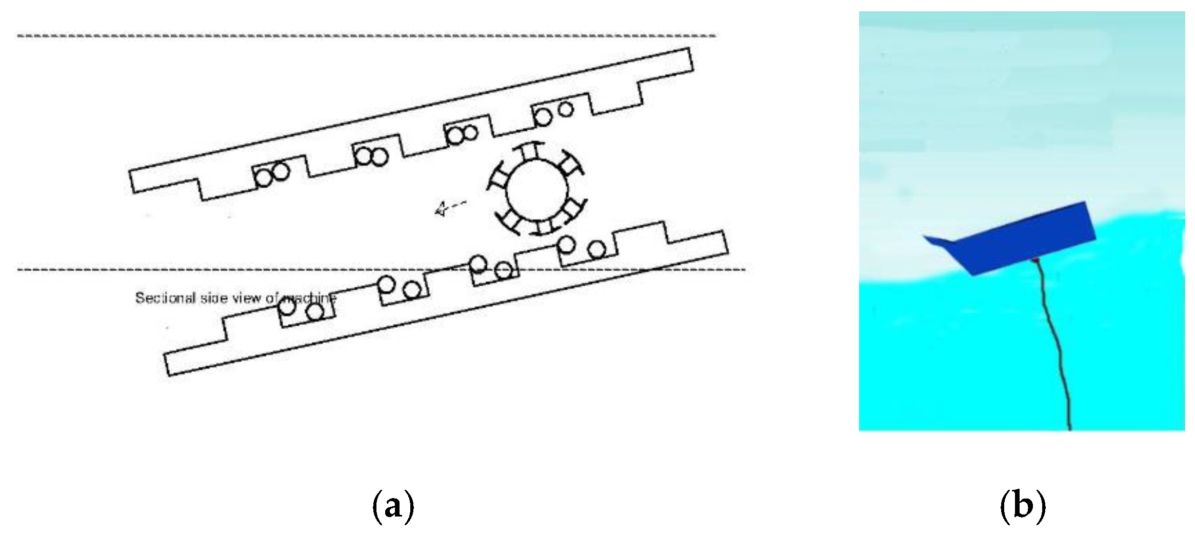
2.1. Working Principle of the Proposed Generator

The working principle of generator comprises two steps. The center of the generator is pivoted to the sea bottom by a rope to stabilize the body during wave motion [17]. As shown in Figure 3, when a wave approaches the face of the generator, it causes a lift of height H in regard to the tail. This drives the rotor from the face to the tail of the generator for a time period t .
In step 2, shown in Figure 4, as the wave leaves the generator, the tail reaches the apex of height H in regard to the face of the generator. This causes the rotor to traverse back to the face of the generator and takes a time t , such as the former one. This system is a rolling asynchronous electrical machine operating as a wave energy converter.

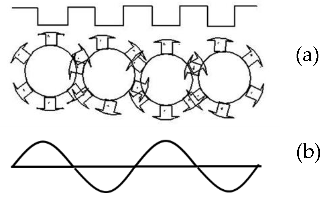
2.2. Generation of EMF

When the rotor moves from face to tail, a sequence of positive and negative pulses of EMF is alternatively generated in conductors located in stator slots due to pole change, as shown in Figure 5. The sequence of the stator EMF pulses reverses and repeats as the rotor traverses back to the face of the generator.

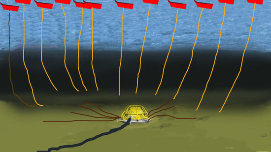
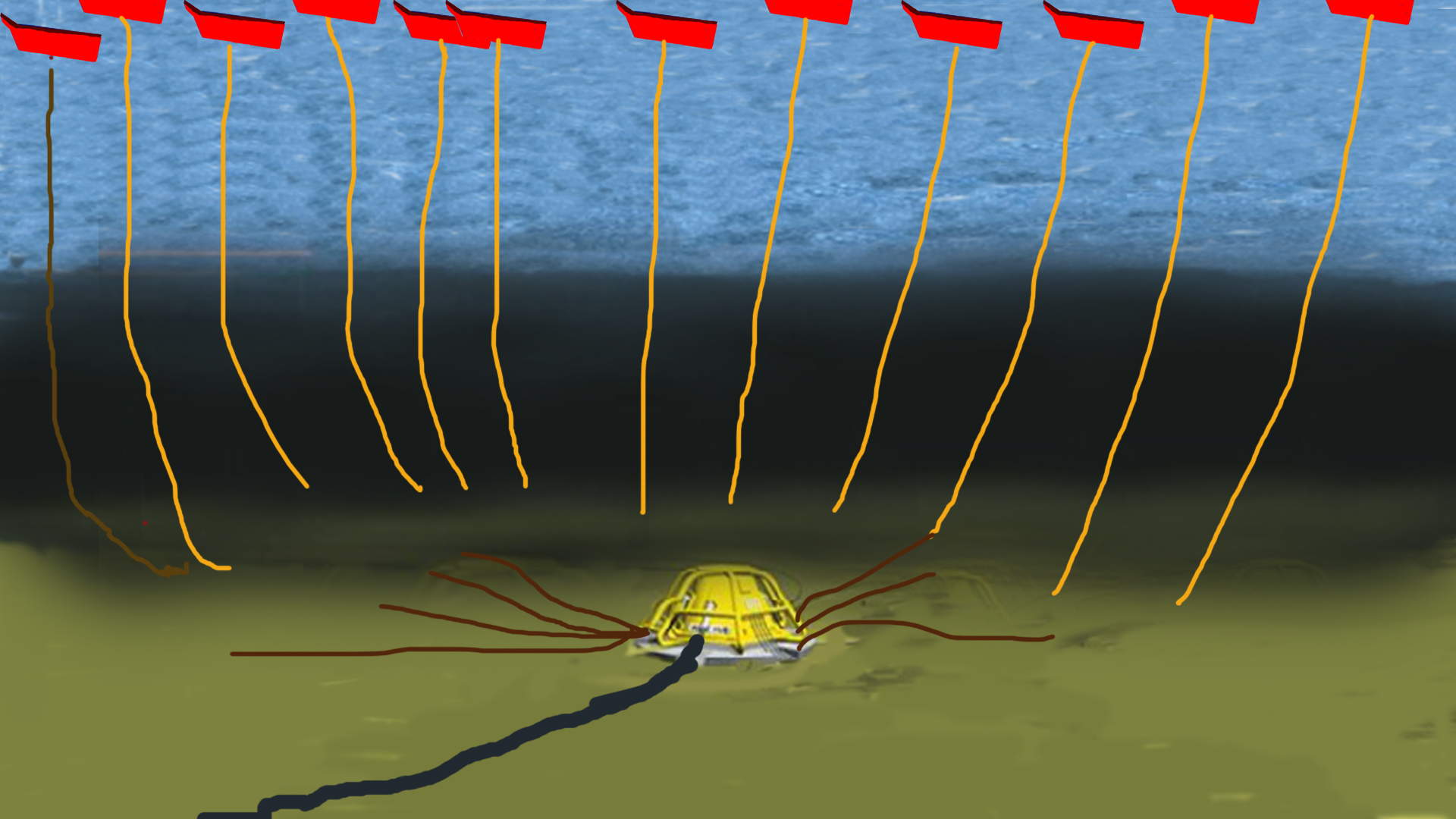
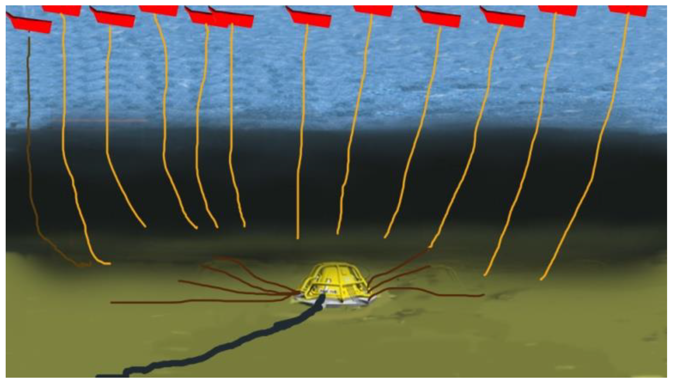
2.3. Plant Overview and Installation

The dimensions of the generator depend on the location and ocean topography (average wave height, average power, and time period of waves). The number of generators required depends on the frequency and energy of the waves in the selected area. Each generator is pivoted towards the sea bottom, as shown in Figure 6. A power control unit is connected in tandem to each generator to process power before it is fed into the local grid. As shown in Figure 6, a central hub takes the feed from each generator and the power control unit and supplies it to a shoreline-based substation via transmission cables [9,10].

3. System Design

3.1. Materials Required for System Design

The materials used for a conventional electrical machine design can also be used for the proposed generator. Silicon steel (CRNGO) is preferred in rotor and stator fabrication to minimize losses. The rotor and stator winding is made up of copper and the wire gauze can be calculated based on the required ampere rating and operating voltage. As all ocean wave energy converters are low KV machines, electrical insulation made of impregnation varnish, resin, and mica can be used according to IEC standards. The generator enclosure is usually made from a lightweight hydrophobic material, such as aluminum or hard plastic. Hard plastic is also used in air bags or air fillers and generally consists of nylon 66.

3.2. Proposed Design

The design of the machine is divided in four phases:
(1)
Design of the stator;
(2)
Design of the rotor;
(3)
Design of the winding;
(4)
Design of the air-sealing hydrophobic body.
A detailed description of these phases is presented below.

3.2.1. Stator Design

The stator is composed of two slotted plates with a concentric single-phase armature winding. The design of the stator requires parameters including the total length of the wave energy converter, stator plate length, number of slots, stator slot pitch, tooth width, slot depth, and depth of the stator core. Slot length l depends on the required KVA. The total length of the wave energy converter is determined from the height and length of the wave.
L 1 = ( H 2 + ( λ 2 ) 2 )
The optimal length is modified as follows:
L 1 = ( H 2 + ( λ 1.6 ) 2 )
The acceleration of the rotor when the converter increases to its maximum capacity can be calculated by Equation (1).
sin ( θ ) = H L 1
From Equations (1) and (5), it is easy to find the length of machine, where t is equal to half the time period of the wave.
L =   a t 2 2
Here, T / 2 t is the time for which the rotor is in an idle position, which should be reduced because of the increasing quality of the output power of the generator.
Both halves of the generated voltage waveform are related to a voltage pulse in individual slots. To improve the quality of the output power, the number of slots in a single stator plate is calibrated based on the time period of the wave.
N s = f × t
Here, f is the grid frequency (50 Hz for India, the United Kingdom, and most of Europe, 60 Hz for the United States) and the speed of the rotor N s is calculated from Equation (8).
Equation (3) gives the EMF generated per slot. Each slot in the stator plate contributes to half a cycle in the sinusoidal EMF seen in Figure 5. The number of conductors is calculated by the EMF generated per slot as follows:
N = E s B a v × K w × 2 × π × f × l × w
where:
w = L n
In general, the number of turns is calculated based on a predetermined length ( l ) of the conductor. The product of the number of conductive layers per slot and the diameter of the wire gives the slot width.
tooth   width = w slot   width
In a low KVA generator, the tooth width is around 0.5–1 inch, whereas in a turbo generator the it is greater than 3 inches. The depth of the slot preferably should not exceed 3 times the slot width, so:
d c = φ 2 × B c × L i
Using Equations (4)–(12), we can design the stator part of the generator.
The time period of the wave is less than that of the rotor for practical ocean wave values. Therefore, every wave energy converter contains many numbers of electrical conversion units.

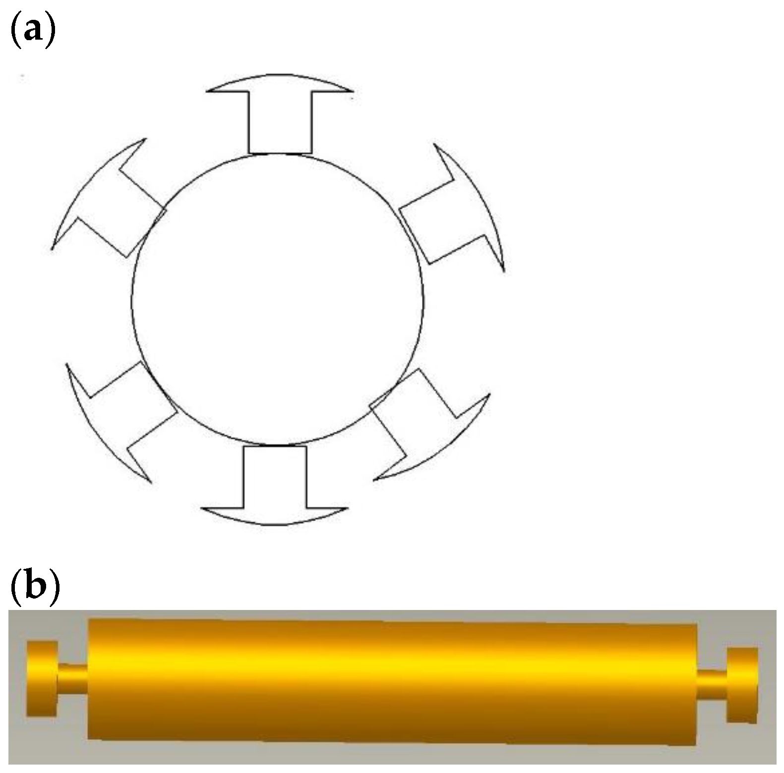
3.2.2. Design of the Rotor

As shown in Figure 7a, the rotor design is similar to a conventional DC generator rotor. The rotor has two circular ends to facilitate motion in machine grooves and an iron shaft to house the rotor winding. Figure 7b also shows a schematic representation of winded poles housed on an iron shaft. The rotor design requires parameters such as the rotor diameter, number of poles on the rotor, rotor length, and number of windings on each pole. Equation (1) gives the rotor velocity, which does not depend on the mass and diameter of the rotor.
The rotor length depends on the voltage and power to be delivered by the machine. In the proposed design, the length of the rotor is equal to the length of the slot in the stator. The ratio of pole arch to pole pitch is between 1 and 5 for a square pole machine. For a proper sine wave, the width of the pole arcs should be equal to w . Therefore, the maximum and minimum pole pitch are w / 2 and w / 5 . The number of poles is determined based on the above considerations.
An inappropriate number of poles causes slot slipping, which leads to frequency and voltage distortion. Here, r is radius of the rotor. The pole number is calculated as follows:
circumference   of   pole   drum = 2 π r
p = 2 π r w
The number of turns is derived based on the flux per pole for a fixed current.
φ = B a v × π × l × D p
where B a v is an average flux density.
φ = N × i × μ × A l
The number of turns on a single pole is calculated through Equation (16). The diameter of the end ring is at least half the diameter of the pole drum in order to maintain and manage mechanical stress on the rotor while rotating.
Two strands of windings from each pole of the rotor are connected to a copper band on either of the end rings of the rotor. These end rings are used to excite the rotor coils into energy conversion. The winding is done in tandem along the length of the rotor. Alternate magnetic poles are achieved by changing the direction of the winding. The rotor excitation current enters through one end ring and leaves through the other. The number of poles in the rotor depends on the diameter of the rotor and the required KVA.

3.2.3. Design of the Winding

The rotor winding is of the salient pole type and alternate poles are achieved by changing the direction of the winding pattern. The number of turns in a single pole is calculated using Equation (15).
Unlike the rotor, the stator winding is not conventional and differs slightly. The concentric stator winding shown in Figure 8 can be made to produce either DC or single-phase AC currents. Single-phase winding of the stator is simple and easy to estimate. Equation (7) gives the number of slots and Equation (8) provides the turns per slot. All the slots are connected in series and EMF is recorded from two ends of the slots.

3.2.4. Design of the Grooves

Grooves act as connectors between the stator and rotor and are filled with ball bearings to house the end rings of the rotor. This minimizes frictional losses and rotor vibration during generator operation. Grooves and ball bearings are two of the most important design components for seamless operation of the proposed design.
The rotor excitation voltage is fed through the conductive bus strip (excitation bus bar) located at the center of the groove, with rotor end rings in contact on both sides. The excitation bus bar is insulated, except at the contacts of the end rings. Grooves completely hold the rotor and help it in its motion (the groove height is less than the rotor end ring radius). Additionally, grooves are attached to stator plates through an insulated material.

3.2.5. Design of the Hydrophobic Body Seal and Parts Assembly

The generator assembly includes stator plates, a rotor, and grooves sandwiched and bolted in an iron yoke. The stator plates form the roof and base of the generator inside the iron yoke (hydrophobic body) between two groves. The rotor with the end rings is placed in groves in such a way that the pole drum faces the stator plate. Air vents are provided on top of the yoke to enable cooling in the generator.
The hydrophobic body of the converter has three chambers made from a lightweight hydrophobic material (aluminum). The top and bottom chambers are filled with air balloons and the middle one hosts the designed linear rotating electrical generator.
Figure 9 shows the shape of the sealing vessel and is designed in such a way so as to provide maximum lift when the wave hits the face of the converter. Maximum lift of the converter enables the maximum amount of energy to be extracted from ocean waves.

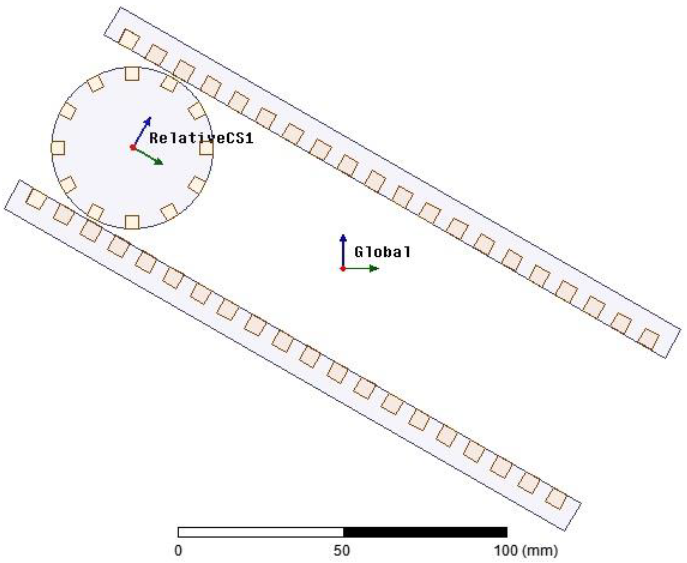
4. Modeling and Simulation

A virtual simulation study with the help of finite element analysis is carried out on the proposed design to understand the flux linkage throughout the generator. In addition, a scaled-down prototype is fabricated using locally sourced materials to further validate the simulation analysis and proof of concept.
A 2D finite element analysis (FEA) is performed using the electrical parameters of the generator. Figure 10 shows that the geometry of the generator chosen for the FEA is analogous to the physical system. In this generator are two mechanical coordinates. One of them is the distance between the center of the rotor and the end of the stator plate. The other one is the angle of rotation of the rotor with respect to a coordinate system stacked onto the rotor. A complete parametric design is shown in Figure 11. The parametric design allows detailed analysis of the generator at any selected rotor position. Figure 12 shows magnetic flux distribution due to an excited rotor in an arbitrary position.

Proof of Concept and Prototype

The design prototype is limited based on the availability of resources and materials that are sourced locally. The protype does not include any plastic enclosures, since the lab testing is conducted in a controlled environment. The prototype contains a rotor with two stator plates, and each plate has 45 slots configured based on the availability of the material. Each stator plate has 12 poles in total, with a slot width of 1 cm. A 22-gauze copper wire weighing approximately 4 kg is used to wind both the rotor and stator in the prototype. Finally, all of the generator stator plates are sandwiched together around the rotor to enclose the magnetic loop around the generator. Figure 13 shows the prototype of the designed generator. The relative dimensions of the prototype are obvious from these figures.

5. Results and Discussion

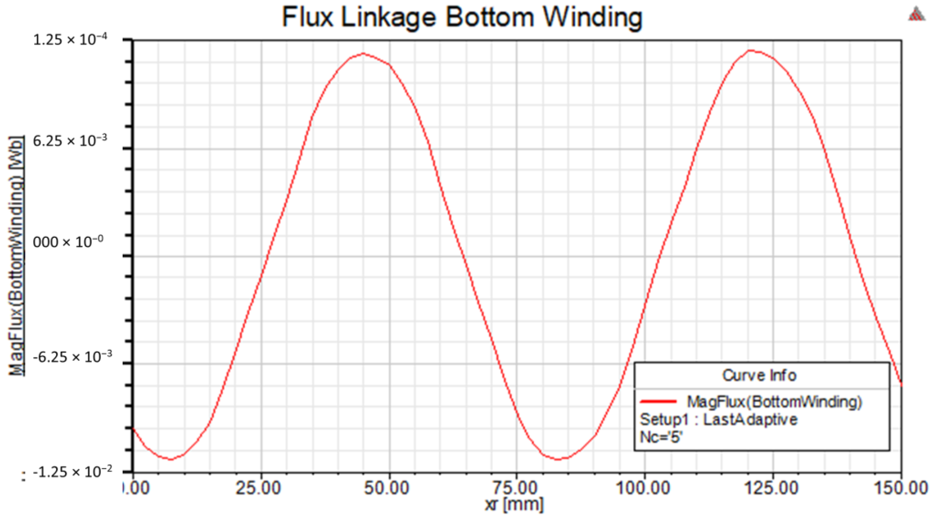
5.1. Simulation Results

Using the parametric FEA simulation, the flux distribution of the stator winding can be evaluated. The stator winding comprises two coils on both the top and bottom plates. Figure 14 shows the direction of the current in the bottom coil.
Figure 15 shows the sinusoidal flux linkage in the bottom coil of the stator winding due to the excited rotor motion. The bottom coil turns five times and generates a maximum flux linkage value of around 13 mWb.
As part of the simulation study, a sensitivity analysis is also carried out to tune the design parameters. Figure 16 shows the flux linkage versus the linear position of the rotor with respect to the number of coil turns in a stator winding.

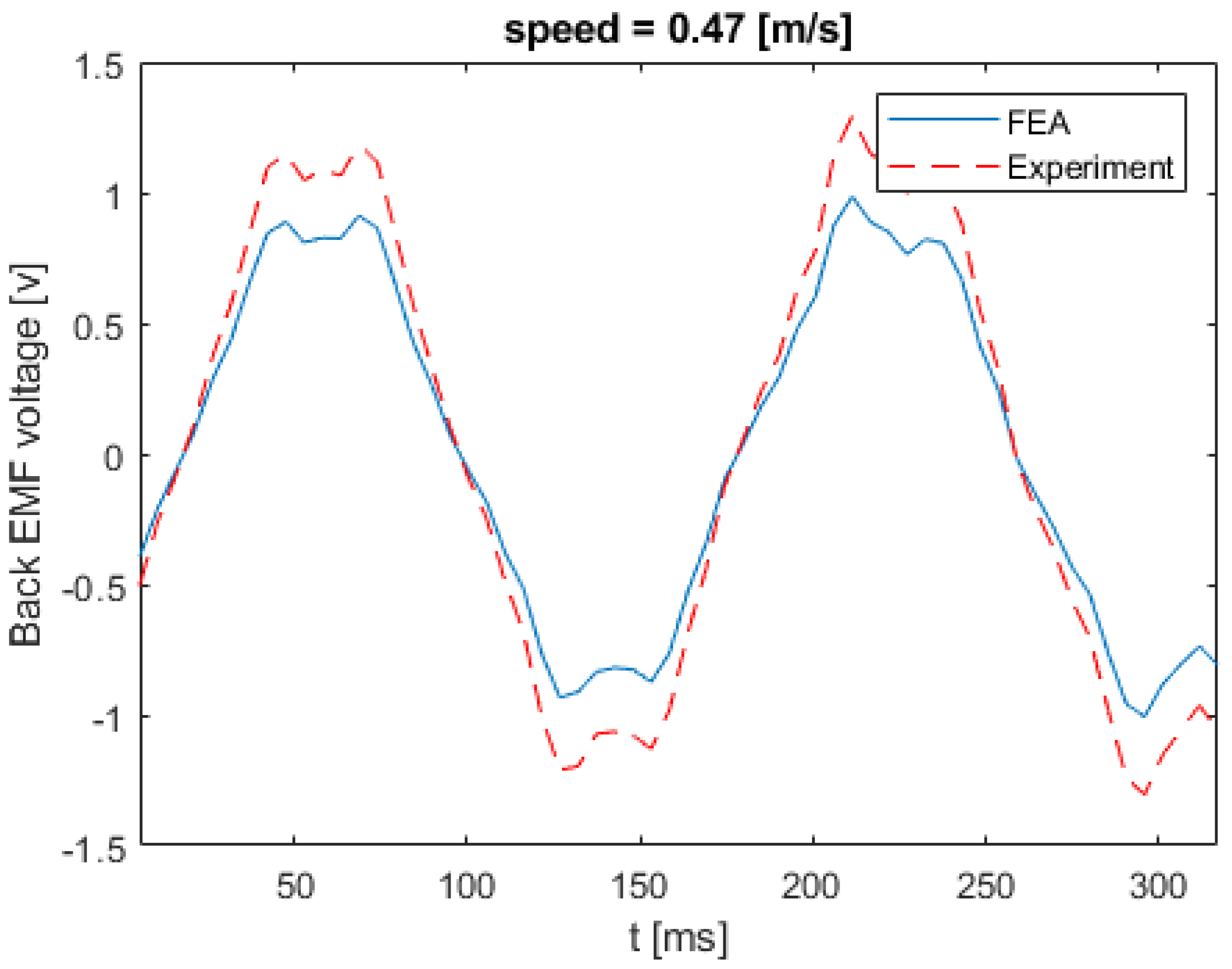
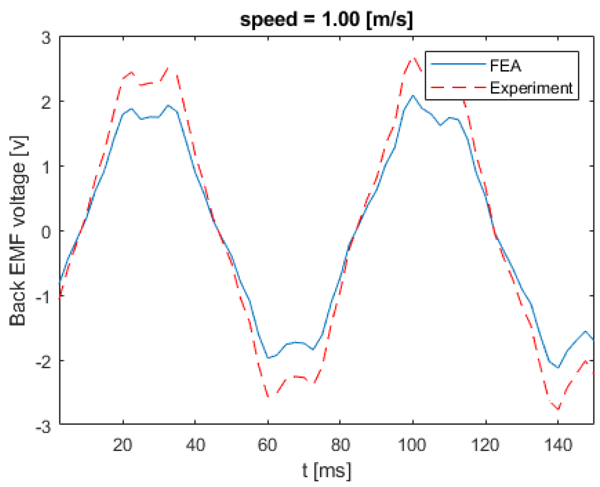
5.2. Prototype Testing Results and Comparison

Figure 17 shows the back EMF voltage in a stator winding when the linear speed of the rotor is equal to 0.21 m/s. The numerical and experimental data differs by an error margin of 25%. Figure 18 illustrates the back EMF voltage when the linear speed of the rotor is 0.47 m/s. The peak of the back EMF increases with the increase in the speed of the rotor. Figure 19; Figure 20 show the back EMF voltage for linear rotor speeds of 0.74 m/s and 1 m/s, respectively.

6. Conclusions

Wave energy is one of the potential resources containing a high energy density per volume of water. Although there are many methods available to harness electrical energy from waves, none of them have succeeded in harnessing the full potential. Many of those methods have complex designs, poor efficiency, are extremely expensive, and require thorough maintenance. These factors hinder the feasibility of wave-energy-based power production. The huge number of intricate moving parts in traditional wave energy converters, such as turbines and gear boxes, reduces the efficiency of the system. In this paper, a novel rolling electrical generator for wave power generation is proposed and designed, with the objective of providing a simplified design, minimal maintenance, and optimal efficiency of the overall system. This design makes use of the sinusoidal motion of a wave (prime mover) to generate electrical power. The proposed design cuts down the levels of power conversion by one order to improve the overall efficiency. The design is validated by both the simulation and experimental results as a proof of concept. The approximate cost estimated to install the proposed design at a capacity of 1500 MW in costal India at a 10% rate of each machine is around $400 million USD.

7. Patents

Praveen L. V. N. Damacharla, “A Floating Wave Energy Conversion System”, filed in the Indian Patent Office, Chennai, TN, India, May, 2011. Application no: 1635/CHE/2011 (Online).

Author Contributions

Conceptualization, P.D.; Data curation, A.J.F.; Formal analysis, P.D.; Investigation, P.D.; Methodology, P.D.; Project administration, P.D.; Supervision, P.D. and A.J.F.; Validation, A.J.F.; Visualization, A.J.F.; Writing–original draft, P.D. and A.J.F. All authors have read and agreed to the published version of the manuscript.

Funding

This research received no external funding.

Acknowledgments

The author would like to thank Nagababu Koganti for editing the manuscript to improve the English writing and Narasimha Raju for providing feedback regarding the results of the paper.

Conflicts of Interest

The author declares no conflict of interest.

Abbreviation

NOMENCLATURE
B a v Average air gap flux density.
T Average time period of wave in seconds
t Time taken to rotor from one end to another end in seconds
L Length of the stator plate
L 1 Total length of wave energy converter
g Acceleration due to gravity
H Average height of the tide
λ Wave length
E s Maximum output voltage
K w Winding factor
N Number of turns
ψ Flux linkage
φ Flux per pole
a Acceleration of rotor
f Frequency of generation
N S Number of slots
w Total slot width (tooth width + slot pitch)
μ Permeability of material
p Number of poles
D Diameter of the rotor
r Radius of rotor

References

  1. Henderson, R. Design, simulation, and testing of a novel hydraulic power take-off system for the Pelamis wave energy converter. Renew. Energy 2006, 31, 271–283. [Google Scholar] [CrossRef]
  2. Everett, R.; Boyle, G.; Peake, S.; Ramage, J. Energy Systems and Sustainability: Power for a Sustainable Future; Oxford University Press: Oxford, UK, 2012. [Google Scholar]
  3. Jacobson, P.T.; Hagerman, G.; Scott, G. Mapping and Assessment of the United States Ocean Wave Energy Resource; Electric Power Research Institute: Palo Alto, CA, USA, 2011. [Google Scholar]
  4. Karayaka, H.B.; Mahlke, H.; Bogucki, D.; Mehrubeoglu, M. A rotational wave energy conversion system development and validation with real ocean wave data. In Proceedings of the 2011 IEEE Power and Energy Society General Meeting, Detroit, MI, USA, 24–28 July 2011; pp. 1–7. [Google Scholar]
  5. Negri, M.; Malavasi, S. Wave Energy Harnessing in Shallow Water through Oscillating Bodies. Energies 2018, 11, 2730. [Google Scholar] [CrossRef] [Green Version]
  6. Hazra, S. Power Generation and Energy Storage Integration for Wave Energy Conversion System; North Carolina State University: Raleigh, NC, USA, 2017. [Google Scholar]
  7. Czech, B.; Bauer, P. Wave energy converter concepts: Design challenges and classification. IEEE Ind. Electron. Mag. 2012, 6, 4–16. [Google Scholar] [CrossRef]
  8. Drew, B.; Plummer, A.R.; Sahinkaya, M.N. A Review of Wave Energy Converter Technology; Sage Publications Sage UK: London, UK, 2009. [Google Scholar]
  9. Damacharla, L.V.N.P. A FLOATING WAVE ENERGY CONVERSION SYSTEM. 2011. Available online: http://ipindia.nic.in/ipr/patent/journal_archieve/journal_2011/pat_arch_052011/official_journal_27052011_part_i.pdf (accessed on 26 June 2019).
  10. Damacharla, P. Design of Linear Rotating Generator for Wave Energy Converter. In Proceedings of the International Conference Renewable and Sustainable Energies 2010 (ICRSE 2010), Hyderabad, AP, India, 18 December 2010; p. 4. [Google Scholar]
  11. Clément, A.; McCullen, P.; Falcão, A.; Fiorentino, A.; Gardner, F.; Hammarlund, K.; Lemonis, G.; Lewis, T.; Nielsen, K.; Petroncini, S.; et al. Wave energy in Europe: Current status and perspectives. Renew. Sustain. Energy Rev. 2002, 6, 405–431. [Google Scholar]
  12. Pyrhonen, J.; Jokinen, T.; Hrabovcova, V. Design of Rotating Electrical Machines; John Wiley & Son: Hoboken, NJ, USA, 2013. [Google Scholar]
  13. Say, M.G. Performance and Design of AC Machines; English CBS Publishers Distributors: New Delhi, India, 1995. [Google Scholar]
  14. Fang, H.-W.; Song, R.-N.; Xiao, Z.-X. Optimal Design of Permanent Magnet Linear Generator and Its Application in a Wave Energy Conversion System. Energies 2018, 11, 3109. [Google Scholar] [CrossRef] [Green Version]
  15. Singh, S.K. Rolling Along an Incline. Available online: https://cnx.org/contents/MymQBhVV@175.14:qte40QR6@9/Rolling-along-an-incline (accessed on 11 May 2019).
  16. Leijon, M.; Danielsson, O.; Eriksson, M.; Thorburn, K.; Bernhoff, H.; Isberg, J.; Sundberg, J.; Ivanova, I.; Sjöstedt, E.; Ågren, O. An electrical approach to wave energy conversion. Renew. Energy 2006, 31, 1309–1319. [Google Scholar] [CrossRef]
  17. Mei, D. Electrical thrust in opposite direction of aggressive submarine. Mar. Electr. Electron. Technol. 1995, 2, 30–35. [Google Scholar]
Figure 1. Diagram showing forces of the rolling body.
Inventions 05 00003 g001
Figure 2. Sectional side view of the linear rotating generator.
Inventions 05 00003 g002
Figure 3. Step 1: The sea wave is approaching the face of the converter: (a) cross-section view; (b) graphical representation.
Inventions 05 00003 g003
Figure 4. Step 2: The wave is leaving the converter via the tail: (a) cross-section view; (b) graphical representation.
Inventions 05 00003 g004
Figure 5. EMF wave production in single-phase generator when the rotor is moving from head to tail: (a) cross-section view of the stator and rotor; (b) corresponding sinusoidal wave form.
Inventions 05 00003 g005
Figure 6. Concept diagram of a wave energy conversion plant in the ocean using linear rotating generators for wave energy conversion.
Inventions 05 00003 g006
Figure 7. (a) Front view of the rotor (semantic diagram). (b) Side view of the rotor (solid state diagram).
Inventions 05 00003 g007
Figure 8. Single-phase concentric winding.
Inventions 05 00003 g008
Figure 9. Block diagram of a total wave energy converter with casing.
Inventions 05 00003 g009
Figure 10. Prepared geometry for finite element analysis (FEA).
Inventions 05 00003 g010
Figure 11. Defined coordinate systems.
Inventions 05 00003 g011
Figure 12. Flux lines due to an excited rotor.
Inventions 05 00003 g012
Figure 13. Prototype design: (a,b) top and bottom stator plate winding; (c) rotor without winding; (d) rotor with winding; (e) enclosed complete wave energy converter.
Inventions 05 00003 g013
Figure 14. Configuration of the current direction in the bottom coil.
Inventions 05 00003 g014
Figure 15. Linkage flux to bottom coil due to excited rotor movement.
Inventions 05 00003 g015
Figure 16. Variation of linkage flux versus variation of the number of poles.
Inventions 05 00003 g016
Figure 17. Back EMF voltage for linear speed of 0.21 m/s.
Inventions 05 00003 g017
Figure 18. Back EMF voltage for linear speed of 0.47 m/s.
Inventions 05 00003 g018
Figure 19. Back EMF voltage for linear speed of 0.74 m/s.
Inventions 05 00003 g019
Figure 20. Back EMF voltage for linear speed of 1 m/s.
Inventions 05 00003 g020

