Review

Current Advances in Ejector Modeling, Experimentation and Applications for Refrigeration and Heat Pumps. Part 1: Single-Phase Ejectors

CanmetENERGY Natural Resources Canada, 1615 Lionel Boulet Blvd., P.O. Box 4800, Varennes, QC J3X1S6, Canada
*
Author to whom correspondence should be addressed.
Inventions 2019, 4(1), 15; https://doi.org/10.3390/inventions4010015
Submission received: 14 January 2019 / Revised: 25 February 2019 / Accepted: 26 February 2019 / Published: 6 March 2019
(This article belongs to the Special Issue Thermodynamics in the 21st Century)

Abstract

:
Ejectors used in refrigeration systems as entrainment and compression components or expanders, alone or in combination with other equipment devices, have gained renewed interest from the scientific community as a means of low temperature heat recovery and more efficient energy use. This paper summarizes the main findings and trends, in the area of heat-driven ejectors and ejector-based machines, using low boiling point working fluids, which were reported in the literature for a number of promising applications. An overall view of such systems is provided by discussing the ejector physics principles, as well as a review of the main developments in ejectors over the last few years. Recent achievements on thermally activated ejectors for single-phase compressible fluids are the main focus in this part of the review. Aspects related to their design, operation, theoretical and experimental approaches employed, analysis of the complex interacting phenomena taking place within the device, and performance are highlighted. Conventional and improved ejector refrigeration cycles are discussed. Some cycles of interest employing ejectors alone or boosted combinations are presented and their potential applications are indicated.

1. Introduction

Research into alternative energy conservation technologies and refrigeration working fluids is ongoing and low temperature heat upgrading has become an important part of the overall effort to reduce the impacts of global warming on the environment. Ejector-based systems, which are thermally activated, provide a potentially promising solution, particularly for moderate heating or cooling applications, refrigeration and air conditioning. They can recover low-grade energy available as waste heat in most industrial processes and use renewable energy or any other source at low cost.
The ability for ejector-based refrigeration systems to recover waste heat and use working fluids innocuous to the environment attracts high interest among those developing applications in refrigeration and other industrial areas. For this purpose, it is necessary to improve the ejector performance, which is generally modest and particularly sensitive to back pressure conditions.
An ejector is a passive compression device with no moving parts (Figure 1). It is thermally activated by a high-temperature fluid stream, transferring energy to a low-pressure stream, propelling it in the process to intermediate conditions through the partial transfer of momentum. The resulting flow discharges at a stagnation pressure halfway between the primary and the secondary pressures. The single-phase compressible ejector type with air and steam has been the most used [1]. Generally, low-grade waste heat is the energy source and depending on its quality and availability, ejectors may use it to provide a compression duty in various cases of refrigeration needs or for tasks of fluid transfer in several industrial and process applications.
Due to the complexity of the flow physics involved, their design has often been empirical or semi-empirical for a long time. Nevertheless, for environmental and energy-saving reasons, there has been a strong resumption of interest in this technology. Ejectors have, thus, evolved to be an important focus of research over the last few decades, even though the technology is not new and was commonly used in the past in jet refrigeration systems, besides several niches of industrial applications [2]. However, there remains much room for further developments in order to make these applications more competitive in an area essentially dominated by mechanical compression technology. Given the current environmental context and rising energy costs, waste heat recovery by means of ejectors offers an interesting potential for cost-effective refrigeration and reduced energy consumption. Waste heat from industrial processes, automobiles, renewable solar, biomass or geothermal sources may serve for ejector activation. Current investigations on ejector refrigeration systems (ERS) include stand-alone units, compressor-ejector, absorption-ejector hybrids and several other combinations intended for refrigeration and industrial use.
Existing literature mainly focused on refrigeration, even though potential applications in other areas exist and perhaps need to be given more attention. Comprehensive reviews were performed in recent years and due to the large amount of material, some focused on applications in specific fields and others covered too wide a span of ejector fields to provide sufficient detail on several technological aspects.
An early review by Sun and Eames [3] established a state of the art of the theoretical designs and studies of supersonic ejectors, besides providing an overview of their experimental application. The authors discussed mathematical modeling concepts for design, based on the thermodynamic approach. They also outlined the limitations of 1D and 2D modeling, which depended on many empirical coefficients, making it difficult to use.
Because of the flexibility and reduced cost of analysis provided by theory, many models were developed, mostly for design. Progress in the mathematical modeling of ejectors was updated by He et al. [4] in this respect. Their work provided a comprehensive summary of the relevant models available and highlighted their main features, providing constitutive equations, assumptions and solution techniques. Abdulateef et al. [5] reviewed the status of solar-driven ejector technologies and provided a discussion with a summary of several cycle options for solar-driven ejector cooling systems as well as the economic and environmental aspects of the corresponding refrigerants.
Rahamathullah et al. [6] not only focused on the background principles of ejector design, but also on the recent improvements in ejector refrigeration technologies. Chen et al. [7] revisited new technological developments in terms of ejector performance enhancement techniques and refrigeration-cycle integrating ejectors. It was pointed out that most of the work performed was limited to theoretical analysis thus restricting the understanding of practical applications. They concluded that even though several studies claimed substantial performance improvements, they still lacked experimental validation for consistence. In the case of solar-activated ERS, they underlined the fact that energy storage remained to be further researched in order to lift the dependency on ambient conditions, which poses a major technical problem for the technology to be adopted.
An update by Chen et al. [8] on ejectors and their integration in refrigeration applications led the authors to the conclusion that experimental validation of the theoretical work remained to be widened. They concluded that the ejector being the heart of ERS systems and combinations with other technologies, more reliable ejector and system modeling, in steady and unsteady conditions had yet to be achieved.
Subsequently, Besagni et al. [9] updated the status of ejector activities, covering a wide range of studies and the corresponding refrigeration applications. The review includes a detailed analysis of ejector operation in ERS and its many combinations with other technologies. Effects of geometry, operating conditions and refrigerant impacts on performance were provided. Little and Garimella [10] proposed a further overview of recent work, focusing on selected aspects of ejector characteristics and use in chiller applications.
Generally, aspects falling outside the refrigeration scope, recent modeling advances, internal flow structures and visualization have received little attention or were not sufficiently discussed, due to the tremendous number of papers, most of which could obviously not be introduced in sufficient detail to the reader.
Existing ejector studies in the literature, typically found in specialized papers or reviews, are often developed independently in the framework of specific science and engineering fields. Examples include a wide variety of processes where ejectors may be applied. Due to various scientific and technical backgrounds required in conventional as well as in emerging engineering avenues, wide differences in the approach, terminology and performance criteria are common but seldom looked into. Thus, they have covered aspects of the ejector technology that are not handled by existing reviews only on refrigeration applications, and making that information accessible represent important objectives towards bridging the gap between professionals seeking to use ejectors in their respective fields. Building on diversified previous research, the proposed review brings out the most prominent findings in ejector technology, design methods, concepts and applications in a coherent and structured development. Single-phase and two-phase ejectors have been mostly researched in recent years, with the focus on refrigeration. The application potential of ejectors in other areas of interest remains under-represented in current reviews. Moreover, single and two-phase ejectors differ in several aspects (flow physics, performance, application, etc.) and a considerable amount of research material is available for each type. Current reviews generally present both types as ejector technological variants, at the expense of restrictions in the treatment of all the information available. Given the importance of these variants, their specific differences and treatments, a separate development is undertaken on each one in its own right for the sake of clarity.
Consequently, single-phase compressible flow supersonic ejectors will be treated in the present development. Its main distinctive features include and are not limited to the following elements:
  • Ejector fundamentals’ discussion of conventional ejector types and extension to more recent concepts employing complex geometries for the nozzles and the mixing chambers.
  • Treatment of single-phase and two-phase ejector variants in separate developments for a full account and analysis of their progress.
  • Inclusion of ejector operational features, conditions affecting stability and performance, such as external constraints, internal geometry, flow regimes as well as many other considerations, which are thoroughly described and discussed in detail.
  • Existing and potential ejector applications, beyond conventional refrigeration systems and selected from different areas of specialties (buildings, transportation, industry and several other domains). Their discussion aims to trigger a better exchange of information and bridge between professionals of different backgrounds and objectives.
  • Modeling methods, their types and particularities thoroughly dissected to provide guidance, depending on the research objectives pursued. Typical analytical and numerical (computational fluid dynamics, CFD) models to serve as a common basis for the vast majority of similar research are proposed.
  • Provision of very detailed, abundantly discussed information on the fundamental elements serving as building blocks to help structure such models. Further, a thorough discussion of the modeling works available in the literature supported by visualization and experiments complements this information.

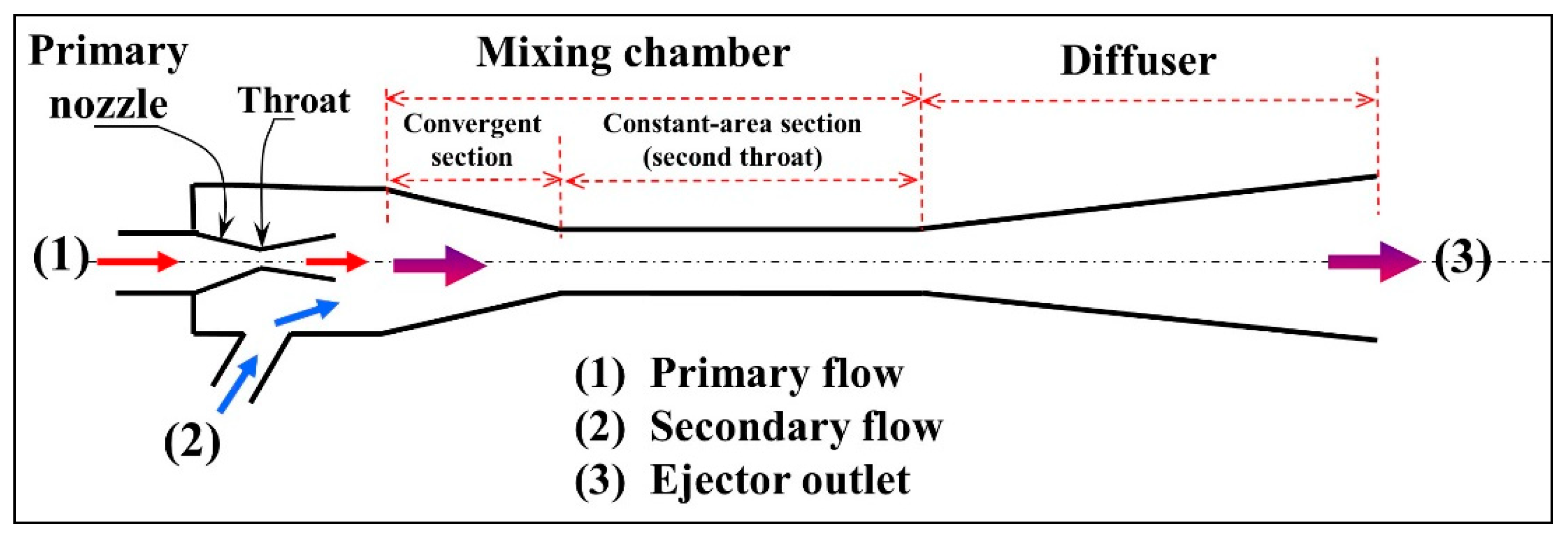
2. Ejector Fundamentals
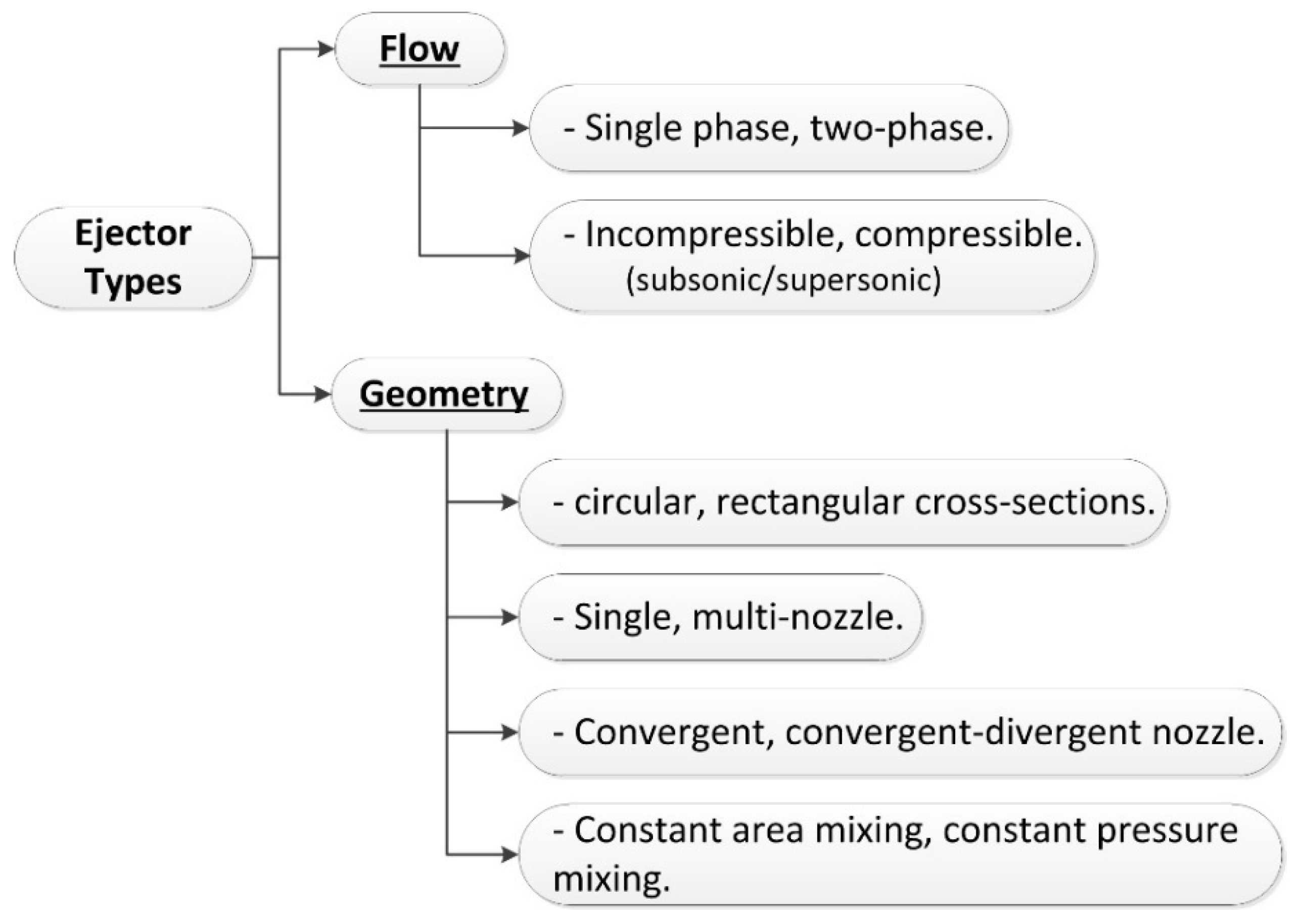
Among the important ejector advantages are the relative simplicity of construction and operation, low cost and low maintenance. Overall reliability stemming from the absence of moving parts attract many researchers’ preference despite the relatively modest performances and limited operating flexibility of the device in comparison with other conventional technologies.
Ejector study is, however, still challenging due to the complex flow process taking place within them, as a result of their internal geometry, several interacting phenomena such as supersonic conditions, shock wave formation, possible condensation and turbulent mixing of two streams in dynamic and thermal non-equilibrium in a very short time and restricted space.

2.1. Ejector Types

Ejector types are mainly classified with respect to their geometry and to the nature of the internal flow (Figure 2).
Ejectors can be single-phase or two-phase, compressible or incompressible flow devices, depending on the fluid flow combination (all liquid, all vapour, liquid-vapour, vapour-liquid). In principle, ejectors may have different shapes, such as rectangular or circular cross-sections, single or multi-nozzle but the cylindrical, single nozzle type is the most used given its simplicity. The compressible flow ejectors comprise single-phase and two-phase types and are those mostly encountered in niche applications, but the potential exists for their application in many other domains. The working process in all ejector types is the same. As already stated, ejectors induce a low energy stream by momentum and energy transfer from a high energy stream. Two-phase ejectors operate with incompressible liquids (primary stream) and are generally referred to as jet pumps. The liquid stream at high pressure is accelerated to a moderately high velocity jet, generally through a converging nozzle. When they operate with compressible fluids, they are referred to as supersonic ejectors and the primary stream is expanded to choked state in a converging-divergent supersonic nozzle. The two streams mixing process can also be achieved by a constant area or a constant pressure approach.

2.2. Ejector Geometry

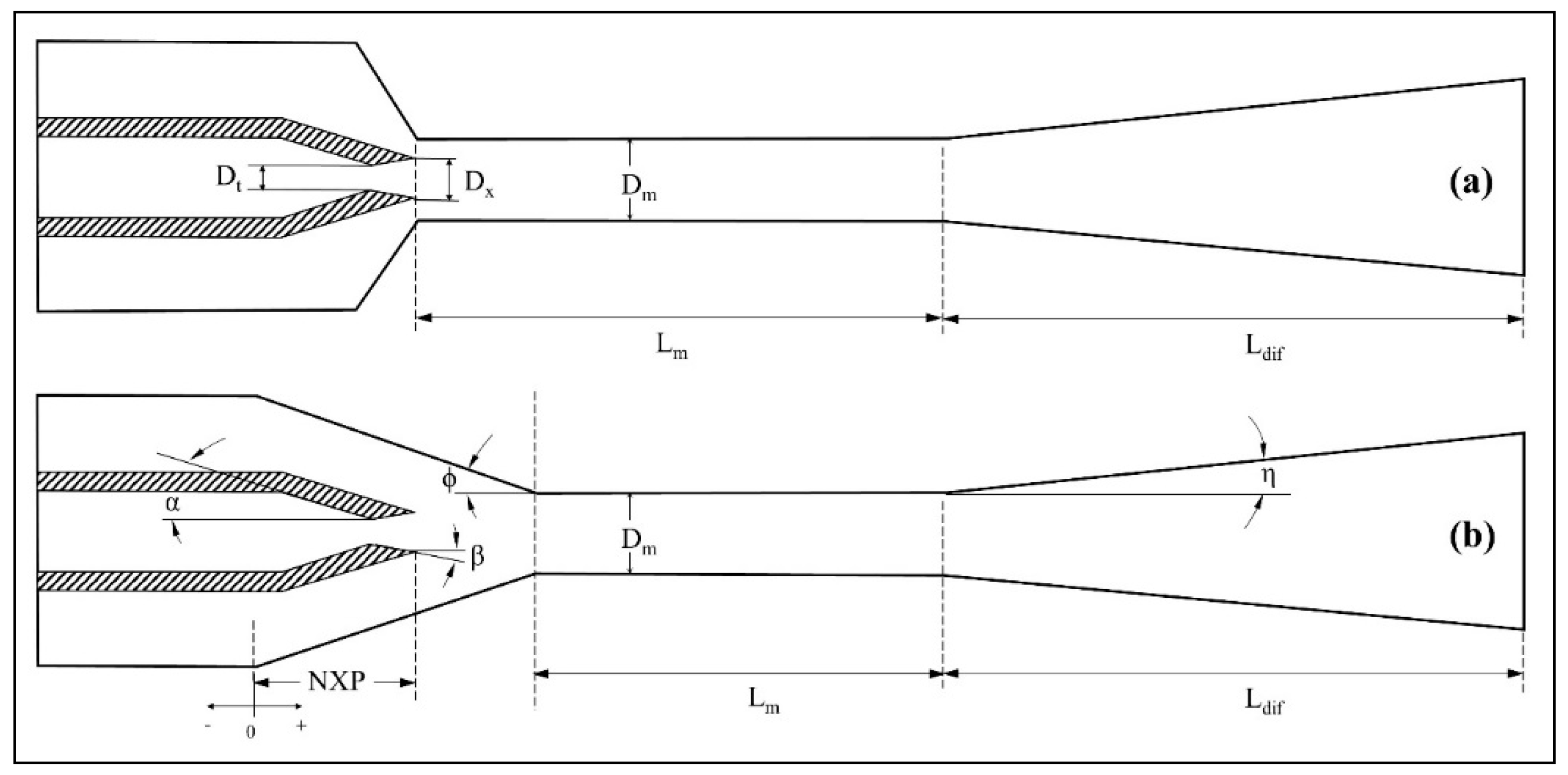
2.2.1. Conventional Ejector

Figure 1 schematically represents a typical ejector lay-out, consisting of two distinct parts generally cylindrical but other cross-sectional shapes also exist, depending on the application environment. The first part is a primary nozzle, which may be simply convergent or convergent–divergent and used to expand a primary fluid, converting in the process its potential energy into kinetic energy. The primary nozzle convergent outlet corresponds to the first throat of the ejector. Primary fluid flows directly to the nozzle inlet. The external part of the ejector constitutes in effect the secondary nozzle and comprises three zones: the convergent section, the second throat or constant-area section and the diffuser. The convergent suction chamber that primary and secondary streams generally run into, guide both flows to the ejector second throat in the form of a cylinder with constant cross-section. This converging portion of the suction chamber accommodates the positioning of the primary nozzle (which can slide back and forth inside the chamber) as well as stream interaction and mixing. In the current literature, this zone and the second throat are also referred to as the mixing chamber. The diffuser consists of a divergent, generally a reversed cone, following immediately after the second throat. Diameters and lengths of different parts, their relative positions coupled with the fluid type and working conditions determine the ejector capacity and performance.
Keenan et al. [11,12] proposed two ejector design methods for constant area mixing (CAM) and constant pressure mixing (CPM), respectively. The constant-area-mixing principle (1942) first introduced a constant cross-sectional area for the entire mixing chamber, at the inlet of which the primary nozzle outlet is positioned, favouring high entrained mass flow rates (Figure 3a).
The design concept of constant pressure was subsequently introduced in 1950. This principle is the most frequently used nowadays, considered to provide better performance and more favourable comparison against experimental data. The geometry of a constant pressure design includes a variable cross section zone immediately before the constant cross section part (Figure 3b), with the primary nozzle exit located at the inlet or within this zone and providing a wider range of condensing pressures [13,14,15]. These authors compared numerically and experimentally CAM and CPM concepts under the same operating conditions and for several boiler and evaporator temperatures with steam, confirming that the CAM offers higher entrainment but lower compression than CPM.

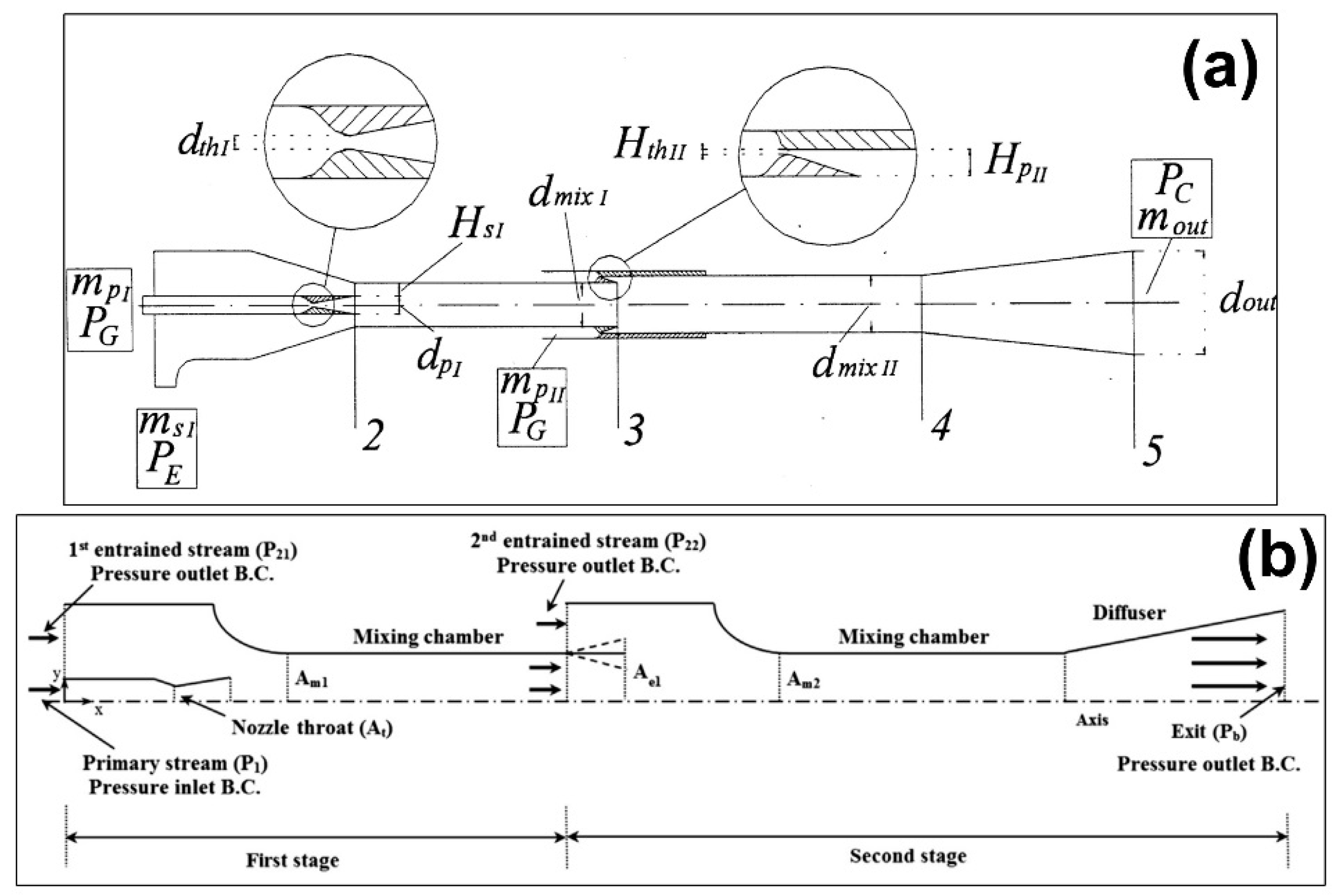
2.2.2. Other Geometry Concepts

Ejector performance characteristics need to be maximised in order to make the technology more competitive and encourage its application. Alternative ejector designs seeking to improve performance were proposed. Work performed by Cao and Ling [16] suggested a design in which direct interaction between the primary and secondary fluids was first avoided in order to lessen the impact of the hydrodynamic non-equilibrium losses by circulating the secondary flow through a porous duct located behind the primary nozzle. It was believed that by preventing the large eddy generation irreversibility resulting from direct mixing, the impact of the encounter between the two streams would be attenuated. The authors numerically investigated the feasibility of the concept by comparing its performance with a conventional ejector of the same geometrical and operating conditions. They noted a reduction of the suction pressure by almost 36%.
Grazzini et al. [17,18] seeking to enhance the compression ratio, proposed a two-stage conventional ejector based on the CAM approach. This design consists of a first stage without diffuser out of which the combined stream becomes the secondary flow of a complete second stage with diffuser (Figure 4a). Kong and Kim [19] conducted a further study based on ideal gas to limit the momentum waste during the discharging process and mixing, occurring in a conventional ejector. In this study, they proposed a 2-stage ejector in which the redundant momentum of the discharged flow is used to improve overall performance. Preliminary results of the two-stage ejector-diffuser system (Figure 4b) showed the favourable capacity of collecting the extra momentum and increasing the entrainment effects of the system.
In order to take advantage of both CAM and CPM concepts and enhance the ejector entrainment ratio while it is maintaining or increasing, Eames [20] proposed a new design method. This latter is based on the concept of constant rate of momentum change (CRMC). The resulting geometry profile of the ejector body (external nozzle, Figure 5) is such that at the design point, the thermodynamic shock is alleviated as the flow passes through, resulting in improved pressure lift and entrainment ratio.
A theoretical comparison of two-stage and CRMC based jet pump cycles was performed by Eames et al. [21]. Results showed better overall performance of the CRMC system, due to its considerable reduction of the primary flow rate in comparison to the two-stage ejector, and because of the fact that system optima are not necessarily the optima of individual components. Experimental data performed with R245fa by Ablwaifa [22] reported a slightly higher critical condensing temperature obtained by the optimized CRMC ejector than a conventional ejector for the same operating conditions. A recent experimental comparison of the CRMC ejector versus the CPM ejector was performed by Kitrattana et al. [23]. The result shows that at the same operating conditions, the CRMC ejector presents higher entrainment ratio (37–40%) than the CPM ejector, with negligible variation of the outlet pressure. Even more recently Kumar et al. [24] proposed an alternative to CRMC, based on kinetic energy exchange between flow streams, which the authors believe may be closer to ejector flow physics but has yet to be developed and supported by experiments.
Chang and Chen [25] on the other hand proposed the petal nozzle for refrigeration, inspired from a version developed for aerodynamic applications to enhance jet engine thrust (Figure 6a). Its purpose is to maximise the ejector back pressure and entrainment ratios in refrigeration applications by promoting better stream mixing. Their experiments, although limited, indicated some potential performance improvement over a conventional ejector at optimal operations under the same operating conditions.
Around the same period Garris and his team [26,27,28,29,30] proposed the concept of the pressure exchange ejector. It is a dynamic component including a free-spinning rotor mounted on a fixed spindle in the primary side of the fluid flow (Figure 6b) and allowing for this stream to expand more efficiently than it would in a static ejector version, as well as enhancing stream mixing. By means of this technique, which relies on unsteady pressure forces, the intent was to minimize losses due to turbulent mixing. The primary flow velocity would reduce through expansion in the rotor, leading to a high non-dissipative energy exchange with the induced flow. With total pressure contours at different rotor locations, Hong et al. [29] underlined the fact that the momentum transfer by pressure exchange, made on a shorter distance than in a conventional ejector was more efficient. To date there have been no experimental data available for this configuration, due to difficulties in putting it into practice.
Another concept proposed by Pietrowicz and Kasperski [31] consists in a rotating ejector. Mass flow rates and back pressure were fixed, the pressure at the secondary inlet and the entrainment ratio were monitored for comparison with the static ejector. It was found that, for low entrainment ratios, the rotating ejector provided lower secondary pressures than when the ejector was static.
More recently, [32,33,34] conducted theoretical investigations on several other nozzle geometries. In particular, lobed nozzles allow for improving both the entrainment and the compression ratio, according to the numerical and experimental study of [33]. Experiments were performed with nitrogen in an ejector of small dimensions and fixed entrainment ratio. The compression ratio, in comparison to a circular section CPM ejector, was shown to increase by up to 43.5%. There was a total perimeter of the lobes, beyond which there are frictional losses along the wall surfaces, dominated the process and the recovered pressure reduced back to the circular nozzle. Lobed and tip ring nozzles (Figure 7a) were later experimentally investigated by Rao and Jagadeesh [35] to enhance stream mixing. Laser scattering flow visualization experiments on the free jet were conducted on the structure of the flow in such geometries. The entrainment of secondary flow was found to increase by up to 30% but a decrease in the compression ratio of 15% and 50% was observed for the lobed and tip ring versions, respectively.
Kong et al. [34] performed CFD simulations on chevron nozzles (Figure 7b). Results showed average improvements of entrainment and compression ratios of up to 14.8% and 8.5% respectively.
Zhu and Jiang [36] experimented on a bypass ejector with nitrogen for entrainment performance. This geometry differs from the conventional one in that an annular cavity connected with the primary inlet and the nozzle throat is imbedded in the primary nozzle wall (Figure 8), so that a bypass is created. The main primary and the bypass streams mix in the throat zone, inducing a reduction of the mainstream primary flow rate. According to these authors’ results, entrainment ratio increase of up to 31.5% was recorded.
Along a similar line of reasoning, Tang et al. [37] introduced the concept of auxiliary entrainment under the ejector’s critical operating conditions, resulting in the geometry depicted in Figure 9. The idea was to take advantage of the low-pressure potential at different internal ejector locations in order to enhance the entrainment ratio. A CFD analysis of the geometry and internal flow structure indicated that an optimum combination of geometric parameters may be found for the entrainment ratio at each back pressure selected. The concept was applied for cases of MED-TVC desalination systems (multi-effect desalination system with thermal vapor compression) [38,39].
Another concept proposed by Vermeulen [40] is pulsed ejection. A pulsed primary flow is injected with a variable frequency and amplitude. According to the authors, mixing is enhanced and entrainment is improved due principally to the toroidal vortex produced by pulsation. Different types of pulse were tested, and the sinusoidal shape was very efficient.
In summary, Eames et al.’s CRMC solution is simple and has been tested to a certain extent by other researchers, even though more data are still required and extended conditions have yet to be investigated. Complex nozzle geometries as proposed by [24,25,32,34] have not yet been tested experimentally and need further exploration. Some ejector geometries of interest proposed in the literature and introduced above are listed in Table 1, below.

3. Ejector Operation

High energy (high-pressure and temperature) primary flow activates the ejector by expanding in a convergent–divergent nozzle to produce a supersonic fluid flow jet, creating a zone of low pressure around its outlet and initiating secondary flow suction at lower pressure. Under these circumstances, the primary nozzle is only sensitive to its inlet conditions, the primary flow mass flow rate is maximum and the outlet static pressure is low. The primary high velocity jet carries the slow moving, low-pressure secondary flow at its boundary, transferring to it part of its energy by momentum exchange, mainly through shear effect but also by suction effect into the low pressure zone created by the primary flow. The secondary stream accelerates until sonic conditions are reached if inlet/outlet pressure conditions are favourable (i.e., secondary inlet and outlet pressures), while mixing increases progressively. Secondary mass flow rate is also maximum. Ideally, both flows eventually complete mixing to form a unique stream before the end of the mixing chamber. The combined flow resulting from this process then undergoes recompression by going through a series of shock waves before the diffuser. At this point, the flow has become subsonic with a pressure increase across the shock waves. In the diffuser, the flow pressure increases by further deceleration to equate the imposed back-pressure. Since both flow conditions are choked, this regime is typically referred to as a double-choked or on-design condition (Figure 10). If the back pressure increases above the critical value, the secondary flow is not choked anymore (off-design operation) and decreases as the back pressure increases up to a point of ejector malfunction. This process is described well in the literature [7,9].
Figure 11 represents an idealised velocity distribution along the ejector axis showing an abrupt change across the shock wave, generally assumed to be a normal shock in thermodynamic treatment of ejectors. As will be seen in the coming sections, this description is rather simplistic but very useful, as it has served as a basis for most thermodynamic model developments currently available in the literature.

3.1. Performance Coefficients

Ejectors have the capacity to produce entrainment and compression effects as needed in refrigeration. They are also suitable for producing a suction effect and creating a vacuum or enhancing mixing, as may be required in specialised applications such as industrial processes. Ejector performance is defined with respect to the application of interest. The focus here being refrigeration and heat pumping, entrainment and compression are the main parameters characterizing ejector operation. The performance indicators typically used are, respectively, the entrainment ratio ω and the compression ratio τ. In an ejector with fixed geometry, the performance is evaluated at design conditions, which correspond to double choking operation, i.e., when secondary and primary flows at their respective nozzle throats, have reached sonic conditions and ejector performance is then maximised. The entrainment ratio, ω is defined as:
ω = m ˙ s m ˙ p ,
and the compression ratio τ as:
τ = P b P s ,
The entrainment ratio reflects the ejector capacity to draw and circulate low-pressure, secondary fluid while the compression ratio relates to the operation range of working conditions. It is obvious that the higher ω is, the better will be the performance of the system integrating the ejector. Performance maps characterizing such devices are drawn in terms of optimal operating conditions as shown by Figure 12.
An additional performance indicator encountered in the literature is the ejector efficiency, found under different forms. ASHRAE [1] define efficiency as:
η = ( 1 + ω ) ( h b h s 0 ) ( h p 0 h p 0 is ) ,
In this process part of the energy from primary flow pseudo-isentropic expansion in the primary nozzle to suction conditions transfers to the primary–secondary mixture compound, lifting its pressure from suction to rejection levels.
Dvorak and Vit [42] express ejector efficiency in terms of pressure ratios as:
η = ω [ 1 ( P s 0 P b ) κ 1 κ ] / [ ( P p 0 P b ) κ 1 κ 1 ] ,
This expression is derived from compressible flow considerations. It compares the work required by the compression of secondary stream from suction to rejection conditions to the potential energy made available by the primary stream expansion from primary inlet to rejection outlet conditions. The above expressions work fairly well for single-phase ejectors, where both flow streams are gases or vapours.
Later, Elbel and Hrnjak [43] proposed yet another expression in the form of:
η = ω ( h b s , is h s 0 ) / ( h p 0 h b p , is ) ,
In this expression, the ejector efficiency is the fraction of energy made available by the isentropic expansion of the primary stream in the primary nozzle, transferred to the secondary stream, compressing it from suction in the evaporator to rejection in the condenser conditions. The authors consider this formulation to represent better the inter-stream energy exchange in the case of liquid–gas two-phase ejectors.

3.2. Operational Factors

Ejector operation and performance strongly depend on the thermodynamic state of the fluids at its inlet and outlet boundaries, characterized by the respective pressures and temperatures in these locations. The working fluids may be either saturated or superheated. Depending on the fluid used, some degree of superheat may be necessary at the primary inlet to prevent internal condensation during the expansion process. Secondary superheat is generally not an issue and the outlet fluid stream normally superheats to some extent due to the strong internal irreversibility occurring in the mixing chamber. The effect of superheat on ejector performance is generally negligible as demonstrated theoretically and experimentally by previous research [44,45,46,47,48].
For a prescribed refrigeration system operating condition, it is customary to design the ejector to operate in optimal regime. The nominal capacity of the device is determined by fixed source temperatures Tg, Te and Tc at the generator, evaporator and condenser respectively. Generally, these locations are approximated equivalent to the primary, secondary and outlet ports, respectively.
From the viewpoint of ejector operation, these conditions translate into pressures as primary pressure Pp, secondary pressure Ps, and back pressure Pb [46]. Most experimental studies on ejectors reported in the literature use either temperatures or pressures. Most noteworthy of these are the works of [49,50,51,52,53,54,55,56,57].

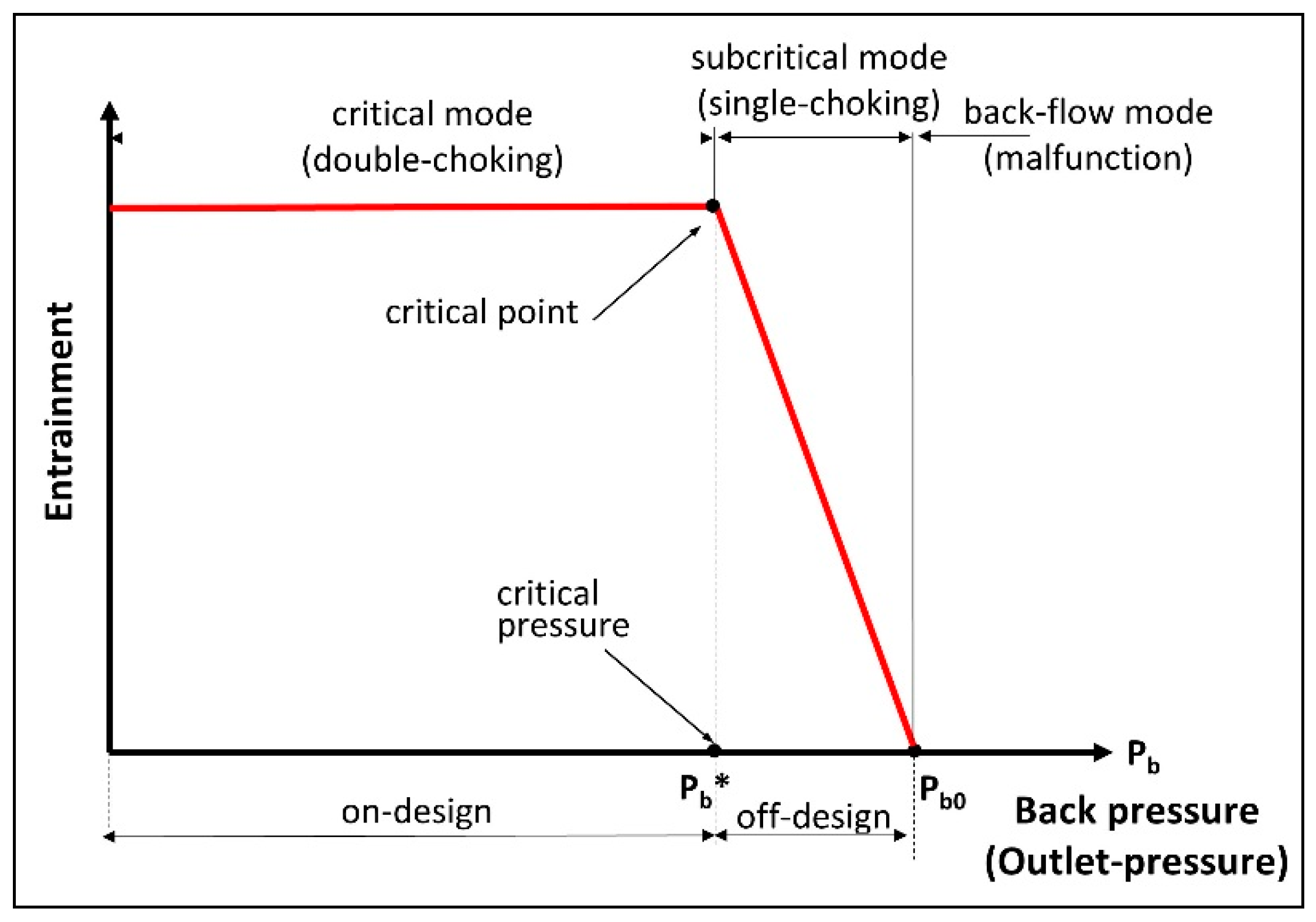
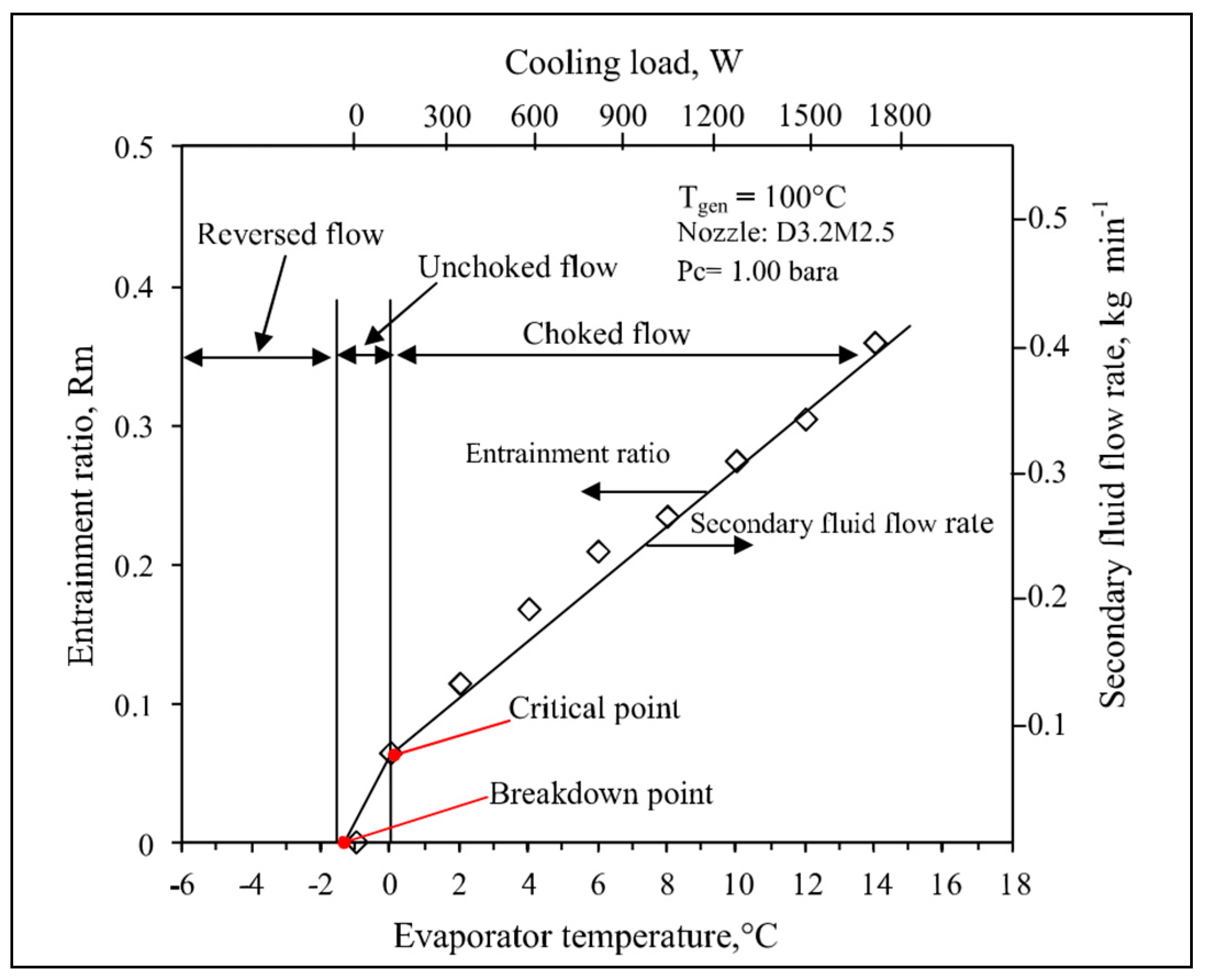
3.2.1. Ejector Operation Curve

The curve ω = f(Pb) is the conventional performance representation of an ejector with given geometry. Inlet pressures and temperatures are fixed; the curve is drawn by varying the back pressure. Figure 10 is a typical characteristic curve of ejector operation, commonly used by researchers and widely available in the literature. The entrainment ratio depends on inlet and outlet total pressures, assuming local velocities negligible in these locations. For fixed inlet pressures, the curve of Figure 10 shows 3 modes of ejector operation, depending on the back pressure value. When this latter is too high (Pb ≥ Pb0) the ejector stalls, resulting in reversed flow into the secondary entrance. By reducing the outlet pressure such that (Pb* ≤ Pb ≤ Pb0) the ejector enters into subcritical mode characterised by a primary choked flow and an un-choked secondary flow which still depends on downstream conditions. This regime is referred to as off-design operation. Further back pressure reduction below the critical pressure Pb* such that (Pb ≤ Pb*) primes the ejector to work in critical mode. In this case, both primary and secondary streams flow at highest mass flow rate (double choking). Further reduction in the back pressure does not affect the flow anymore. The critical mode corresponds to constant entrainment ratio.

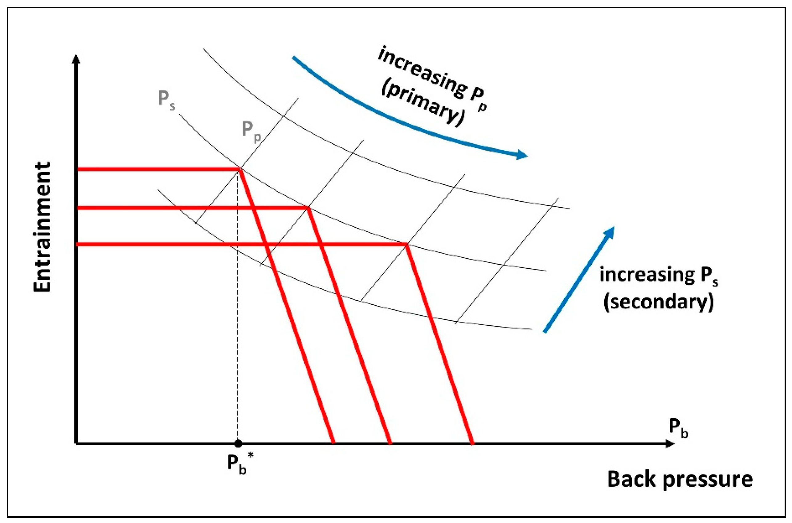
3.2.2. Effect of Inlet Pressures

Primary and secondary pressures modify the operation curve of an ejector with fixed geometry and back pressure.
When the ejector is not choked, the entrainment ratio increases with Pp [9,58]. These phenomena are reported with several refrigerants in the literature [15,45,55,56,57,59,60] and typically represented in Figure 12. In order to draw this curve, the conditions at the generator, evaporator and condenser (primary, secondary and outlet ejector respectively) need to be tightly controlled, a requirement that can only be fulfilled in the laboratory.
As was shown before, decreasing Pb down to its critical value Pb*, increases the entrainment ratio up to its maximum value (choking condition) beyond which no more change occurs. At this condition, if Ps is fixed when Pp increases (Figure 12), entrainment decreases and Pb* increases. When Pp is fixed, increasing Ps increases the entrainment ratio and Pb*.
In order to represent the actual behaviour of a jet pump operation, instead of referring to Pb* as the choking criterion, an alternative representation was proposed by [13,61]. Recently this method was further pursued by Thongtip and Aphornratana [62] where the variation in evaporation temperature associated with the cooling load supplied at fixed condenser and generator temperatures was analysed (Figure 13). This approach reflects better the jet pump performance, operating in an actual scenario.
More generally, a non-dimensional form of operating parameters is used, more often in terms of pressure ratios. Typically Pp/Pb, Pp/Ps and Pb/Ps are, respectively, motive, expansion and compression ratios. They are frequently used in ejector design diagrams and correlations [60,63,64,65].

3.3. Geometry Factors

A fixed geometry ejector works efficiently only in a very narrow range around its design point, given the operating conditions. In off-design conditions, its performance degrades rapidly. Ejector performance is very sensitive to operating conditions and the influence of a number of its geometrical features to various extents. The factors mostly known to be relevant are the nozzle exit position (NXP) and the mixing throat area ratio (ϕ), but parameters such as the nozzle exit area ratio (θ) and the mixing chamber throat length ratio (δ) do influence performance as well. These have been studied numerically and experimentally in various degrees of detail by many researchers, typically [45,46,66,67,68,69], to name only a few.

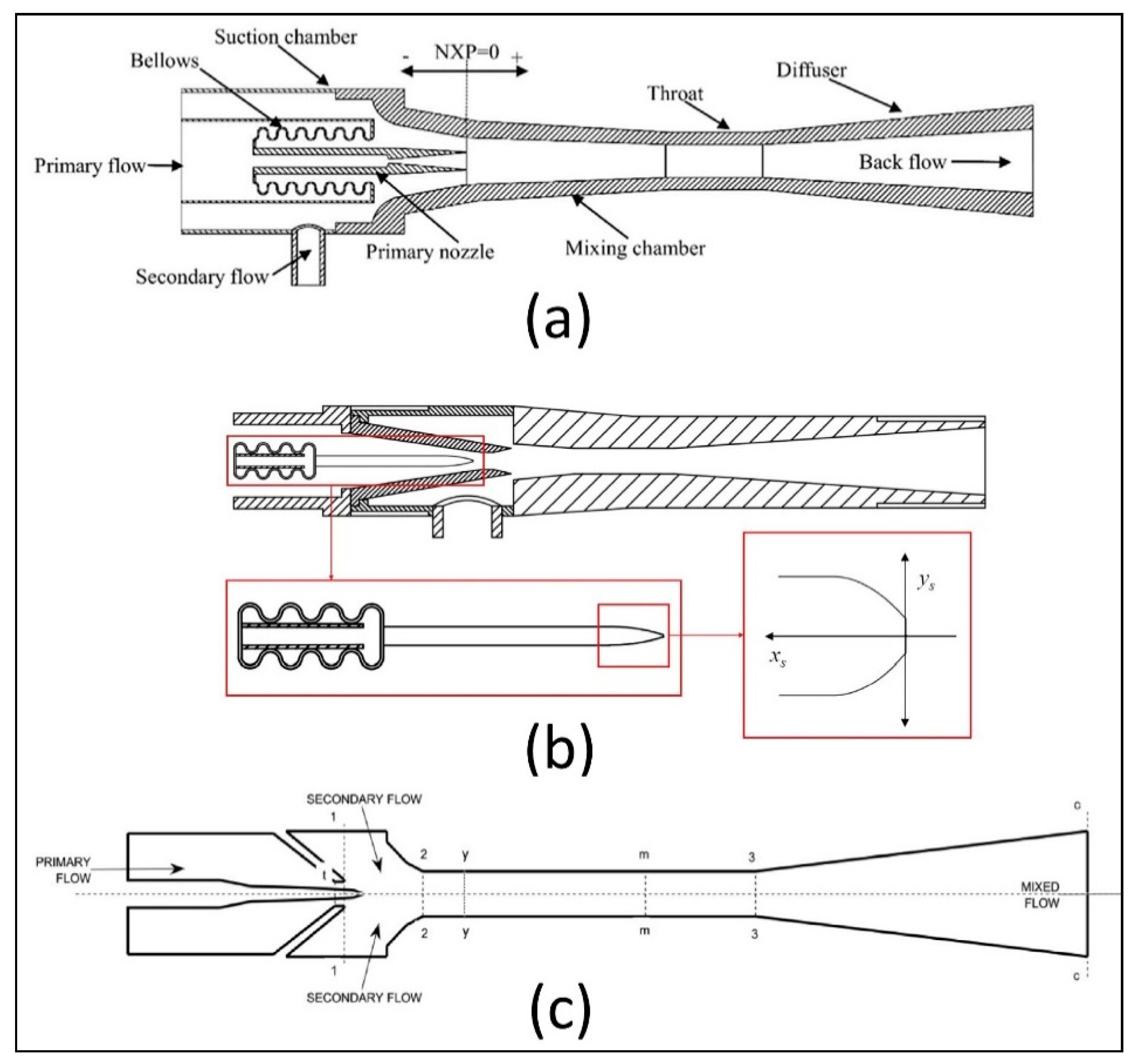
3.3.1. The Nozzle Exit Position (NXP)

The NXP parameter indicates the positioning of the primary nozzle with respect to the mixing chamber. It is generally defined as the distance from the exit plane of the primary nozzle to the entry plane of the converging entrance zone of the mixing chamber [63] (Figure 3b). Others in some cases [70] consider the positioning of the primary nozzle relative to the inlet of the mixing chamber throat, especially in the case of constant area ejectors (Figure 3a).
Varying NXP by axially moving the nozzle forward or backward in the mixing chamber affects ejector performance. This parameter is sometimes presented in its non-dimensional form as NXP/Dm where Dm is the second throat (mixing chamber throat) diameter [64]. For example, Riffat and Omer [71] selected four NXP locations (two negative, one at inlet and one inside the mixing chamber) for an ejector operating with methanol. Maximum entrainment ratio was found to occur for a location outside the mixing chamber for the chosen conditions, in agreement with ESDU (Engineering Sciences Data Unit) recommendations. Unlike Riffat and Omer, Rusly et al. [72] did not observe any important change of performance within the range of ±20% NXP variation of their ejector design.
A CFD analysis performed by Pianthong et al. [15] on a steam ejector confirmed the NXP effects on performance. They observed that for given operating conditions, only one NXP value corresponded to optimal operation. Similar results were obtained experimentally by Eames et al. [73] with R245fa on a CRMC type jet pump. Varga et al. [68] reported that the optimal value of NXP coincided with the maximal value of critical back pressure.
Chen et al. [74] studied numerically the effect of both the NXP and the length of the mixing chamber throat in a non-dimensional form for a case of natural gas application. Unlike Varga et al. [68], their findings indicated that NXP presents a different optimum for the entrainment and compression ratios and greatly depended on working primary pressures. Several more simulation and experimental works are worth mentioning in this respect [75,76,77,78,79,80]. They reported optimal ejector operation in terms of NXP for entrainment and compression ratios with several refrigerants, different locations in the mixing chamber and various degrees of performance improvements. Overall, what emerges out of all these findings is a fair consensus on the existence of a value of NXP corresponding to optimal ejector operation, even though more effort is needed to clarify issues like specific effects of the fluid and conditions of operation on both entrainment and compression ratios. The effect of NXP remain very dependent on the fluid type, geometry and operating conditions and can only by adjusted on a case-by-case basis.

3.3.2. Primary Nozzle Exit Area Ratio

The primary nozzle geometry is generally expressed in terms of the nozzle exit area ratio defined as θ = ( D x / D t ) 2 and reported to affect ejector performance. For fixed operation conditions and overall geometry, a variation of this ratio influences the primary stream expansion. Eames et al. [64] tested two such nozzles having the same throat and divergent angle for which they represented the ejector entrainment ratio as a function of the nozzle expansion ratio ( P p / P s ) . The results indicated for selected θ a corresponding optimal ω value existed. On the other hand, when θ increased ω decreased, which the authors attributed to the increase in the degree of over-expansion occurring in the nozzle flow.
CFD-based assessments of steam ejector, were performed by [81,82], who compared three nozzles differing only by their outlet diameter but submitted to the same operating conditions in order to maintain the same primary mass flow rate. It was found that all nozzles achieved the same entrainment ratio ω, while the back pressure increased with the Mach number Mx at the nozzles outlet.
Lin et al. [79] numerically performed similar work with a natural gas ejector by varying the nozzle divergent angle, β. They presented the results in terms of nozzle divergent angle for a fixed secondary mass flow rate and a range of primary throat openings (100% to 50%) by means of a spindle. For full open throat (100%), back pressure increased monotonically with β. As the throat was increasingly restricted, an optimal angle value corresponding to maximum back pressure was identified. This implies that for full throat operation, ω remains constant while the back pressure improves, similarly to Ruangtrakoon et al. [82] findings. With increasing throat restriction, optimal ω steadily increased with a lower rate of increase in the back pressure. The authors attributed the displacement of the optimal angle to the change of the flow inside the nozzle and the critical throat area. This may have as well impacted the importance of the back pressure.
Yan et al. [83] conducted experiments with different angles of the primary divergent while maintaining the back pressure constant. The results indicated a maximum variation in the entrainment ratio of 9% when varying the angle in the range 3.9 to 9.1 degrees. In a recent paper, Thongtip and Aphornratana [84] continued this work experimentally. They fixed the primary mass flow rate and varied the Mach number Mx at the nozzle outlet by changing the cross section area, and all the other conditions maintained constant. The result was that ω moderately improved but the back pressure increased with higher Mx. According to the authors, this may be due to better suction created by higher primary stream velocity, in such a way that the ejector had a stronger drawing potential of the secondary stream and the expansion wave angle being potentially reduced by the lower outlet nozzle pressure, thus resulting in an increase of the effective area for the secondary fluid. The authors pointed out, however, that with a fixed primary flow, there may be a limitation of the heat source in order to produce the design condition for high Mx besides the larger outlet diameter, which may restrict the mixing chamber operation.
Wang et al. [85] numerically assessed the effect of nozzle exit area ratio and surface roughness on homogeneous condensation. According to this investigation an increase of nozzle exit area ratio reduces condensation intensity and lowers the nozzle static pressure but increases liquid mass fraction. Surface roughness, on the other hand, slightly increased the dryness fraction. An overall slight decrease in mass flow rate will reduce ejector performance to some extent, while a sharp increase of entropy generation results in more energy waste.

3.3.3. The Mixing Chamber Shape Effects

The Mixing Chamber Throat Ratio

Also called the second throat ratio or ejector area ratio, this characteristic parameter has an important influence on ejector operation and performance. It is generally defined as the ratio of the second throat cross-section to the primary nozzle cross-section areas ( φ = ( D m / D t ) 2 ) .
It was shown successively by Nahdi et al. [63] and Eames et al. [64], and by later research [47,86,87] that for fixed ejector compression and expansion ratios Pb/Ps and Pp/Ps respectively, an optimal value of φ exists for which the entrainment ratio ω is maximised.
Yapici and Ersoy [14] compared two ejectors under the same operating conditions, respectively with constant area mixing and with constant pressure mixing. They concluded that CAM entrainment ratio was higher than that of CPM but required a higher φ . For the same φ the trend was reversed.
Wang et al. [77] and Sriveerakul [88] drew similar conclusions and predicted an increase of ω with φ until a maximum is reached but the critical back pressure Pb* decreased accordingly. Varga et al. [68] worked along the same lines and concluded that increasing the mixing chamber throat diameter did improve ω. This trend was in line with their experimental investigations on ω and Pb*, respectively.
Jia and Wenjian [89], experimentally evaluated the effects of operating conditions such as primary flow pressures on the ejector system performance with variable and fixed area ratio. They showed that the influence of this factor on ejector performance largely depended on the operating conditions. Yan et al. [83] experimented with R134a and confirmed the existence of an optimal φ for fixed operating conditions which depended on NXP. For high values of φ , the range of optimal NXPs is quite narrow and vice-versa. Recent CFD results with pentane by Mohamed et al. [90] confirm that ω increases and the critical back pressure decreases with φ .
These results imply that for different pressure ratios as would be the case for a wide range of working conditions or geometry changes, φ needs to take different values in order to maintain optimal operation. Under these circumstances, it is clear that a fixed geometry ejector cannot accommodate optimal performance but can work optimally only in a narrow range of conditions. In other words, optimal ejector dimensions for a given operation are not suitable too far away from the design point so that a single geometry can only work satisfactorily in a relatively narrow range of conditions.

The Mixing Chamber Throat Length

There are very few investigations on the effect of the mixing chamber throat length (Lm) and its selection is generally based on empirical and semi-empirical considerations. Established design references recommend length selection typically between 3 and 5 diameters of the second throat, as generally observed with air and steam [1]. However specific designs with diverse fluids, mainly refrigerants, sometimes used up to 15 diameters [34,47,52,91].
Pianthong et al. [15] investigated numerically the Lm effect, for both CPM and CMA steam ejectors in double choking operation. They demonstrated that for fixed conditions, long mixing chamber throats gave larger backpressures but had no effect on the entrainment ratio which remained constant. Sriveerakul et al. [88] were also interested in the effect of this parameter and confirmed that an increase of the throat length did not change the entrainment but increased the back pressure.
Chong et al. [92] proposed an optimization of the ejector design by successively varying several geometrical parameters with the purpose of favouring high compression ratios. This approach resulted in an optimal value of φ = 1.6 for maximum compression ratio. Then, the mixing chamber throat length ratio δ = L m / D m (herein called the second throat ratio) was increased until the compression ratio reached a maximum corresponding to δ = 4. Further length increase of Lm generated more pressure losses and reduced the compression ratio.
Subsequently, however, Chen et al. [74] in a numerical analysis of a natural gas ejector also expressed the mixing chamber influence in terms of δ. Their results indicated that the ejector performance was affected by pressure and entrainment ratios. Approximately the same optimal δ values for both entrainment and compression ratios were found, depending on the primary pressure. It may be noted that the range of operation covered by these researchers did not always correspond to double choking conditions as evidenced by varying performance ratios before reaching plateau levels. Beyond this point, these results are consistent with the findings of Pianthong et al. [15].
The recent experimental results of Yan et al. [83] confirmed that the mixing chamber throat length had a minor influence (less than 2%) on entrainment ratio for given operating conditions. Similar findings were reported by Lin et al. [79], based on CFD analysis for a fixed secondary flow rate of an ejector operated with R134a and variable primary throat geometry (by means of a spindle). The authors expressed their results in terms of the compression ratio increase, showing the existence of an optimal δ value for throat restrictions in the range of 0–50%. It can be deduced from these results that the entrainment ratio also varied accordingly.
Recent work on mixing length aspects of a low AR rectangular supersonic gaseous ejector was conducted by Karthick et al. [93] to ensure proper primary and secondary stream mixing and efficient pressure recovery, based on wall pressure measurements and the use of the planar laser Mie scattering (PLMS) imaging extraction method.

The Mixing Chamber Inlet Angle

The mixing chamber inlet zone of a CPM ejector is a convergent, the cross-section of which, decreases at an angle φ down to the second throat constant cross-section zone (Figure 3b). This angle is generally selected for current ejector design in the range of 10 to 40 degrees, according to ASHRAE recommendations or based on the literature if the working fluids and operation are of the same nature as for the project undertaken. In addition to the investigations on φ and δ effects, Chong et al. [92] tested converging angles as well, ranging from 22 to 38 degrees and found that an angle of 28 degrees was the best compromise for their working conditions.
Similar research was performed by [78,94] who varied the converging angle φ in the range 0–4.5 degrees in the context of desalination. Zhu et al. [78] observed an increase of ω between 0° and 2°, and Ji et al. [94] concluded that ω increases between 0° to 1° to a maximum value. Lin et al. [79] also varied the angle φ corresponding to the inlet cone of the mixing chamber which seemed, however, to be of minor influence.

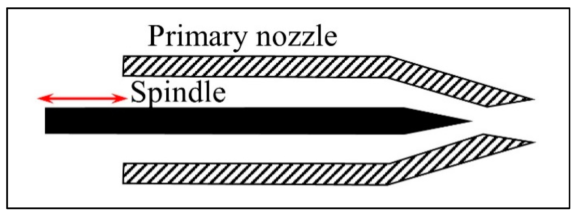
3.3.4. Variable Geometry Ejector (VGE)

A solution to the aforementioned area ratio problem would be to vary the primary nozzle throat area (Figure 14). In practice, variable geometry ejectors (VGEs) consist in inserting a spindle before the primary nozzle and changing its position inside the throat, altering its cross-section area and thus the corresponding area ratio varies accordingly, resulting in the control of the primary mass flow rate. In this way, it is possible for the ejector to work optimally over a range of conditions. Early studies of this effect were performed by [52,58]. The variable geometry ejector has been used by researchers with various refrigerants: CO2 [43], steam [95,96,97], R134a [98,99].
Yapici et al. [67] evaluated experimentally this effect on six ejector geometries with R123, covering a range of area ratios from 6.5 to 11.5 at a fixed compression ratio of 2.47. It was found that the optimal area ratio increased linearly with the primary temperature. Ma et al. [95] investigated experimentally with this procedure in the context of a solar refrigeration application. Varga et al. [68,96] performed a numerical assessment and conducted experiments under various conditions of area ratios in the range 13 to 27, using water as the working fluid. Besides the influence of φ on ω, Varga et al. [100] were also interested in its effect on efficiencies of the different ejector zones. It was found that an optimal value of φ existed, depending on operating conditions. Primary nozzle efficiency remained relatively unaffected or slightly increased with the primary nozzle throat diameter but efficiencies in the suction, mixing and diffuser zones depended on operating conditions.
Ruangtrakoon et al. [82] by numerically simulating ejector behavior at constant φ values, showed that for choking conditions, the critical back pressure increased and the entrainment ratio decreased when increasing the size of the primary nozzle throat area. The reverse occurred when reducing the throat area. Further numerical research by Varga et al. [91], concerned the performance of two variable area ratio ejectors, respectively using refrigerants R152a and R600a for use with a solar energy source. Their CFD simulations showed that performance gains were substantial both in on-design and off-design operating modes. Along the same lines, Li et al. [101] experimentally investigated the performance characteristics of a variable area ratio ejector. The results indicated that the entrainment ratio, pressure recovery ratio and critical area ratio were strongly affected by both primary and secondary pressures.
More recently Thongtip and Aphornratana [84], using R141b, experimented on six nozzle geometries, four of the same throat area ratio but different throats and the other two having the same throats but different throat area ratios. This study confirmed that for every ejector working conditions corresponded a suitable nozzle geometry and shed more light on the main guidelines for such selection. Chen et al. [102] proposed a design model for a VGE based on the method of characteristics that handles the mixing process in cases of both double and single choking operation. In a second paper, Chen et al. [103] focused on solar-powered VGEs which they assessed theoretically and experimentally. Experiments were conducted on subsonic and supersonic nozzles under a variety of VGE operating conditions, and a numerical assessment was performed to explore the driving flow development inside the VGE. The results published by the authors in this context highlighted the importance of the primary nozzle geometry on system performance with varying solar activation conditions.
In order to regulate and enhance the performance of a MED-TVC desalination system, Wang et al. [104] proposed a new adaptive nozzle exit position (ANXP) device (Figure 15a) to enhance ejector performance by self-adjusting the position of the primary nozzle with the change of primary pressure. The mechanism relies on bellows fixed to the ejector in such a way that the variation in primary pressure results in an axial displacement of the primary nozzle, thus varying NXP. A further development by the authors in a separate paper by Wang et al. [105] to auto-tune the ejector area ratio (Figure 15b) used the bellows principle to adjust the spindle position inside the primary nozzle throat.
An additional nozzle geometry shape with a specially designed spindle and a fixed cylinder was proposed by Petrovic et al. [106] in order to hold the nozzle area ratio constant for different spindle positions (Figure 15c). Preliminary theoretical and experimental results have yet to be confirmed by further investigations.

4. Flow Regimes and Internal Structure

4.1. Primary Nozzle Flow Regimes

Possible flow regimes taking place inside supersonic ejectors are described well by Bouhanguel [107]. In supersonic nozzle operation, three different regimes may be encountered, depending on pressure conditions (Figure 16):
  • If the primary inlet pressure is insufficient, the jet will be supersonic in part of the divergent but leaves the nozzle in subsonic conditions due to a normal shock wave formation inside the divergent. This occurrence is a particular case of an over-expanded flow.
  • When the primary pressure increases, the flow becomes an over-expanded jet of conic form with a succession of oblique shocks, generally occurring when the nozzle exit pressure is lower than the reigning ambient.
  • If the primary pressure further increases, then the jet becomes under-expanded and will continue to expand past the nozzle to reach the ambient condition.
In the case of an ejector with induced flow, when the suction pressure of the secondary stream is higher than the pressure at the primary nozzle exit, then the primary stream is over-expanded, becoming the siege of oblique shock waves right at the very exit of the nozzle. In these conditions, the jet contracts such that the contraction angle of the jet core frees more of the cross-section area for the secondary stream flow to be drawn in. This contraction angle increases with the decrease of the jet outlet pressure (Figure 16b).
When the primary nozzle exit pressure is higher than the suction pressure, then the primary jet is under-expanded. After leaving the nozzle, an expansion wave with an even higher expansion angle occurs, reducing the cross-section passage of the induced secondary flow (Figure 16c).
The case when the core jet leaves the primary nozzle at the pressure of the suction flow is ideal but not common in practice. In such a case, the jet core is expected to be straight with no expansion or shock losses.

4.2. Ejector Internal Flow Structure

The operation of the primary nozzle plays an important role in the shaping of the primary jet at its outlet, depending on the expansion ratio imposed by the primary and secondary inlet conditions. Particular ejector geometry and overall conditions set the flow regimes under which the primary and secondary streams will interact, resulting in complex flow configurations. A representative ejector internal structure is shown in Figure 17. It consists of an expansion–compression pattern of waves with varying reflection angles from the boundaries. The shear layer separating the jet core from the suction flow and the centerline zone, which act in the same way as solid boundaries, form these angles along the mixing chamber, as long as stream mixing has not occurred. In this process, the primary flow expands in the nozzle and spreads out to pressure and Mach number, both depending only on the upstream conditions and the ejector design. The shape of the primary jet relies on surrounding pressure downstream from the nozzle exit. As reported by Bouhanguel [107], the following cases may be encountered, typically:
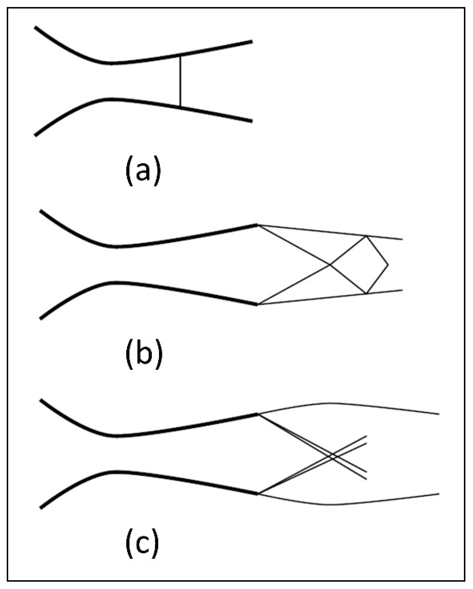
  • Fully developed supersonic flow (Figure 17a): occurs for high inlet pressures and low induced flows. The primary jet is fully expanded in the mixing chamber and the induced flow is equally supersonic.
  • Supersonic flow with secondary sonic throat (Figure 17b): the primary jet expansion is less important than in the preceding regime and the induced flow is higher, reaching sonic conditions in the mixing chamber at a location where the effective cross-section is minimum. Downstream of this point, both flows are supersonic.
  • Supersonic saturated regime (Figure 17c): the primary jet is supersonic with moderately low pressure and the induced flow remains subsonic. A pseudo-shock front sets somewhere between the primary nozzle outlet and the mixing throat inlet.
  • Supersonic regime with double choking (Figure 17d): characterized by double choking, this flow exhibits two distinct pseudo-shocks, the first behind the primary nozzle and the second before the diffuser inlet. This regime occurs for low geometric ratios, corresponding to small mixing chamber sections.
Matsuo et al. [108] estimated that due to flow confinement, a normal single shock is very unlikely. Rather, successive oblique shocks forming a “shock train” are induced because of the interaction with the boundary layer (Prandtl–Meyer expansion–recompression). The shocks involve zones of high and low pressures with the secondary flow alternatively directed towards the ejector centerline and towards the walls. In the case of strong boundary layer/shock interaction, boundary layer separation could occur. Kong and Kim [19] found that the behaviour of the primary jet in a confined environment such as ejectors was different from that of a free jet with the same pressure ratio, differentiating between the nozzle effective and back pressures and suggesting that the effective back pressure should be introduced for higher ejector operation pressure ratios.
The interaction process between motive and suction streams is rather involved and plays a major role in ejector performance [109,110,111]. It gives rise to a momentum exchange through turbulence, formation of a shock train and boundary layer interactions along the mixing chamber length. The shear mixing layer grows along gradually, to eventually form with the wall a minimum cross-section for secondary flow passage. This minimum cross-section is referred to differently by researchers, usually as a thermodynamic throat or critical section but all corresponding to the concept of effective area (Fabri and Siestrunck [112]; Munday and Bagster [113] and many others), where secondary flow is choked and mixing is accelerated.
Behind the shock train, the radial Mach number distribution is not uniform. This is due to residual shocks responsible for subsonic and supersonic pockets distributed along the centerline, even though the pressure distribution in the mixing chamber is at this stage globally uniform. For an ejector operating at its design point, a second shock zone occurs at the diffuser inlet with similar characteristics resulting in subsonic conditions [114].

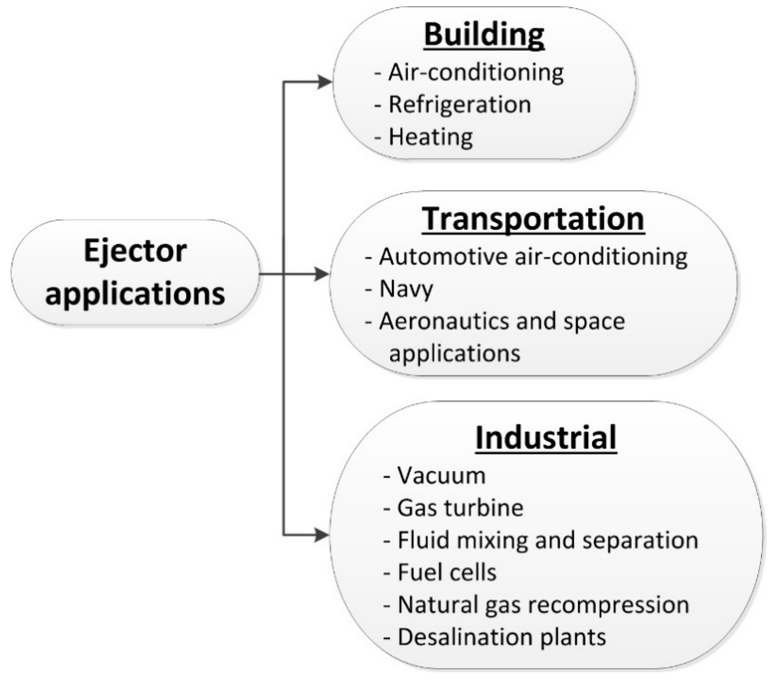
5. Application Potential of Ejectors

An important asset of supersonic ejectors in view of their potential applications is the absence of moving parts, making them reliable with no particular maintenance or related costs. For this reason an ejector may be suitable for applications in many areas (Figure 18), ranging from refrigeration and air conditioning to commercial, industrial and defense applications [115]. In fact, ejectors for compressible fluids are not new and have been known for a long time in niche industrial applications. They were used as steam-jet pumps or gas ejectors but with the currently available refrigerants, alone or in combination with other technologies, further work remains to be done. Systems such as these, operating with appropriately selected low boiling point refrigerants and activated by solar energy, superheat from a compressor discharge, heat engine exhaust or any other energy source at low temperature are very promising. Steam-jet vacuum evaporation has been present for a long time either in large flow rates of chilled water or quick chilling of process fluids and bulk materials. The technology is common in power and energy fields, food and pharmaceutical processing, chemical, petrochemical, pulp/paper and related industries [2].
Sun and Eames [3] summarised the available information on ejectors by areas of applications up to 1995. Very representative updates of the current state of the art were successively brought into the refrigeration domain by many subsequent reviews, as already mentioned. For the sake of conciseness, selected highlights of information will be resumed as appropriate. Additionally, some most interesting applications worth mentioning are reported below for illustrative purposes only.

5.1. Air-Conditioning, Refrigeration and Heating

Ejector operation with induced flow, i.e., corresponding to conditions with a secondary fluid, is the case of interest. The entrainment is due to viscous effects and the amount of secondary fluid drawn into the ejector and its compression are the main performance criteria [75,116]. In such systems, the ejector is the compression device, drawing the refrigerant vapour from the evaporator (cold creation) and compressing it for heat rejection in the condenser. Ejector applications in air conditioning have been among the priority studies of most researchers. Representative references are proposed here in the works of [5,59,116,117,118,119,120,121]. A first prototype of the concept was installed and tested as early as 2001 in a building office by Nguyen et al. [122]. A more recent ERS prototype air conditioner (4.5 kW nominal capacity with R141b), designed for hot climates was tested recently by Thongtip and Aphornratana [123] under laboratory test conditions, where hot water at 90–98 °C was the driving source, the condenser was fed by water at 28–32 °C from a cooling tower and chilled water temperature generally varied between 13.4–16.5 °C.
Refrigeration and heating by means of heat pumps are equally important domains of application still attracting most ejector research. Many good quality works have been proposed with different working fluids.

5.2. Automotive Air-Conditioning

Internal combustion engines waste up to 17% of the fuel through heat dissipation. The radiator coolant is at approximately 80 °C and in sufficient quantity to power an ejector for air-conditioning. Heat recovery from the radiator coolant has been proposed by several researchers to activate a supersonic ejector for cooling the car cabin [124,125,126,127].

5.3. Aeronautics and Space Applications

Ejectors have several applications in this area. They are used to boost the propulsion engines, reduce their signature, ensure air-fuel mixing and cool oil radiators [128,129,130].
Various numerical and experimental studies were performed in the nineties about noise reduction in high-speed civil aircraft and the concept of the mixer-ejector was considered as a promising technology to increase the pumping performance with more completely mixed flows leaving the ejector shroud and consequently reducing the jet exhaust noise. Choi and Soh [131] analysed the process by performing a computational study of the flow field in a two-dimensional ejector nozzle, using a time-iterative full Navier–Stokes in order to capture the complex phenomena inside the ejector flow field. They performed a parametric study and showed that there was an optimum area ratio for the efficient pumping of secondary flow. A similar CFD study was conducted by Gauthier and Birk [132] to simulate an exhaust ejector for infrared signature suppression.
Ejectors with no induced flow may also be used to produce a vacuum effect [133,134,135,136]. In aerospace engineering, thrust augmentation is an area where ejectors play an important role. The vacuum creation feature is used for high altitude testing of propulsion systems by reducing the pressure of test chambers. Numerical studies of the fluid expansion in the nozzle help to optimize the operation and efficiencies of such devices. In this respect, Chen et al. [137] were interested in the use of a second-throat ejector-diffuser system (STED) to reduce the pressure inside a test chamber, in order to simulate high-altitude operation conditions. To this purpose, they impressed a Mach number and a pressure radial profile at the inlet and used a Lagrangian formulation of the equations, where the coordinate lines correspond to streamline and time lines. This method was considered by the authors to be more appropriate for exploring a supersonic flow giving rise to shocks and slip lines. Indeed this approach takes into account the flow deviation and can solve these complex mechanisms more accurately. However, such formulation can no longer be used when the flow is subsonic. Their work was continued by Wang and Chen [133] who undertook numerical and experimental investigations on the system with no secondary influx, in order to determine the threshold pressure inside the chamber below which the STED could operate. Detailed analysis of start and unstart cases by means of pressure and Mach number contours (shocks discs evolution) interpretation allowed the authors to conclude that the supersonic flow was not necessary to start the STED, as would be the case with other technologies such as supersonic wind tunnels. Dvorak [138] conducted a numerical shape optimization of a supersonic ejector for propulsion of an experimental supersonic wind tunnel. The ejector contains several primary nozzles arranged around the mixing chamber wall.
Dong and Mankbadi [139], and Presz et al. [140] conducted CFD studies of ejector/mixer flow with an emphasis on capturing the acoustic disturbances and assessing the mixer/ejector noise suppressor. Beside the capacity of this ejector to reduce noise, it is able to increase the static thrust of the aircraft engines. By comparing their simulations with experimental data, the authors demonstrated the ability of the numerical approach to predict engine thrust and the acoustic waves well.

5.4. Vacuum Creation

In order to produce a vacuum effect, the ejector secondary flow is minimized or simply blocked. Under such conditions the primary jet creates a suction zone behind the primary nozzle outlet [112,141]. This condition results from the nozzle operation which may have different regimes, depending on flow constraints. If the nozzle divergent experiences a normal shock (unprimed nozzle), the secondary pressure hardly decreases for lack of suction. If the primary flow is supersonic, the secondary pressure reduces sensibly and quasi-linearly with the primary pressure (mixed regime, with secondary flow subsonic). At optimal primary pressure, the depression is maximum and the new regime corresponds to the transition condition of secondary flow (subsonic–supersonic). Beyond this optimal pressure, suction performance deteriorates [9]. Vacuum creation has many potential applications in the agri-food or processing industries such as drying, liquid evaporation, juice concentration, gas extraction and odor suppression [1,142,143,144,145,146].

5.5. Gas Turbine Performance Enhancement

Similarly to the automotive concept, ejectors were proposed for gas turbine performance enhancement. In this case, the supersonic ejector is activated by flue gases to precool inlet air before the feed compressor. It is estimated that the turbine power output can increase by as much as 0.7% for every 1 °C drop in inlet air temperature [147]. This operation has the potential to improve gas turbine overall efficiency by about 15% [148].

5.6. Fluid Mixing and Separation

Due to their operation reliability, ejectors find applications in the processes of chemical industries for mixing fluids of different types, conditions and toxicity [149,150].

5.7. Fuel Cell Applications

Ejectors may be used to replace the pumping recovery devices of the hydrogen not consumed by the system. Such replacement saves the electricity consumed by the pumping device and contributes to improve the overall efficiency of the plant [151,152,153,154].

5.8. Natural Gas Recompression Stations

In natural gas transport using pipelines, substantial energy savings may be made by replacing compressors or reducing their duties during the compression process. Ejectors are activated by high pressure gas from the main line to boost low pressure gas [155]. Ejectors activated by natural gas are also used to raise the pressure of waste gas, to satisfy the combustion requirements, and to reduce the concentration of the explosive compound [106].

5.9. Desalination Plants

These installations make use of solar activated ejectors to recompress water vapour before condensation to produce distilled water [156,157,158,159,160,161].

5.10. Other Industrial Applications

With the increased knowledge dissemination on ejector potential and the progress of numerical computing power in recent years, new applications continue to emerge. Cai and He [162] applied a CFD-based procedure to design an ejector to be integrated in a steam turbine system. The purpose is to maintain vacuum, pump non-condensable gas, indirectly enhancing the efficiency of the Rankine cycle.
Similarly Chen et al. [74] relied on numerical analysis to optimize the design of an ejector for natural gas, applied to boost low pressure in a Chinese gas field. Fluent CFD solver was used to perform the design optimization.
Further CFD estimations were performed to assess the potential of integrating ejectors in existing industrial niche applications. For example, Sharifi and Sharifi [163] considered a steam ejector in the context of a specific industrial process, which limited the optimization to the design of the primary nozzle with the aim of reducing steam consumption. The feasibility of integrating a solar-activated ejector cooling system into an existing central chilled water system of 1.43 MW capacity for the climatic conditions in Dhahran was also investigated by Tirmizi et al. [164]. In such conditions with a high average incident solar irradiation, this approach was found to offer a high potential for energy and costs savings.
In the design framework of an ejector-based chiller prototype for commercial and industrial applications, Mazzelli and Milazzo [165] reported the results of a numerical analysis about the ejector internal flow structure in view of optimizing the design and maximize performance. The prototype operating conditions were specified by an industrial partner for a nominal chiller capacity of 40 kW, activated by a 90–100 °C heat source.
An ejector application to a micro-combined heat and power system based on solid oxide fuel cell was reported by Genc et al. [166]. The role of the ejector activated by high-pressure methane is to recycle the anode exhaust gas in order to supply high temperature mixture to initiate the chemical reaction in the reformer. The authors used flow simulation. The numerical investigation of the ejector performance revealed that the fuel inlet temperature and the pressure ratio of the methane to exhaust significantly affect the two main parameters which are the entrainment ratio and the steam-to-carbon ratio.
Another use of steam ejectors proposed by Chen et al. [167] for NOx control in coal-fired power plants suggested significant improvements, particularly at low loads where conventional means of removal become ineffective.
A thermodynamic analysis was undertaken by Sadeghi et al. [168] on a power and ejector refrigeration cycle as well as a desalination system based on humidification and dehumidification processes. A zeotropic refrigerants mixture consisting of isobutene and pentane in 50–50% proportions was employed. A single objective optimization procedure was conducted in terms of exergy efficiency and a multi-objective procedure in terms of net power output and refrigeration capacity was also performed.

6. Ejector Modeling Methods

Ejector modeling is a low-cost alternative to experiments. Design modeling focuses on sizing ejectors for a specified operation. Working away from the design point generally results in off-design operation. Simulation models predict ejector operation and help optimise performance at the lowest cost.
Ejector design and optimal operation are, thereby, the aspects most addressed. For example, several research works determined optimal geometries for specified application conditions [41,58,169], studied the effect of mixing chamber diameter on entrainment, [14,170,171], and calculated the optimal ejector dimensions of an ejector in order to deliver a fixed cooling capacity [58,169].
Thermodynamic and analytical models solve the integral form of the conservation equations to provide operation variables and design information at specified ejector locations as well as overall performance parameters [12,44,137,172].
CFD modelling, on the other hand, relies on the solution of the conservation equations in their differential form, giving access to spatial distributions of the flow-controlling variables, making accessible local and global ejector analysis. Early CFD work on ejectors suffered from limitations in computational power [71,173] but rapid developments in computational platforms now offer adequate capabilities to handle complex flows such as those encountered in supersonic ejectors and irregular geometries as found in special situations [130].
In this section, the intent is to give an overview of the modeling progress currently available from the preliminary design offered by analytical and thermodynamic procedures to detailed local simulation provided by powerful CFD tools. Earlier theoretical and modeling work on ejectors has been well summarized by Sun and Eames [3]. For further details on the treatment of this important topic, the reader may also refer to the dedicated review by He et al. [4].

6.1. Analytical Modeling

Earlier theoretical and experimental work using gases and vapours was based on the thermodynamic and compressible flow theory concepts developed by Keenan and his collaborators. Two design methods emerged out of these efforts, due to Keenan et al. [11,12], who proposed two thermodynamic models with constant area and constant pressure mixing respectively, but ignoring heat and friction losses. They first introduced the constant-area-mixing principle (1946) and developed their mathematical development by assuming that the working fluid behaved like an ideal gas and operation was in critical conditions. This approach considers a constant cross-sectional area for the entire mixing chamber (Figure 3a). The concept of constant pressure mixing was introduced later (1950). Nowadays, it is the most frequently used for its performance and more favourable comparison with experiments. Constant pressure mixing design includes a variable cross section zone immediately before the constant cross section part (second throat), where the nozzle exit is located (Figure 3b).
Keenan and Newman’s theoretical analysis made many simplifying assumptions which subsequent works gradually attempted to lift totally or partially. The fluid molecular weight was experimentally shown by [174,175,176] to affect ejector entrainment ratio. DeFrate and Hoerl [177] modified Keenan and Newman’s theory based on perfect gas assumption and a unique fluid to extend it to dissimilar primary and secondary fluids with different molecular weights and temperatures. The approach was adapted by Khoury et al. [178] for refrigeration applications and compared the results with experiments on Hexane and n-Butane but agreement between the theory and experiments was poor. This model was later modified by Lallemand et al. [179] by bringing up the differences existing in the three regime types of ejector operation, i.e., mixed, transition and supersonic regimes. Experiments performed respectively with refrigerant couples (R11, R114) and (R113, R142b) in mixed and transition regimes were in relatively good agreement with model predictions. A wider range of validation with new eco-friendly refrigerants has yet to be explored.
Modifications to these models successively accounted for effective area concepts, delayed mixing, internal losses [9,45,51,112,113,180,181] and several other upgrades were introduced subsequently such as the use of real fluids and mixtures, 1D flow assessment, on-design and off-design operations, correlations for hypothetical throat estimations, etc. [110,182,183,184].
The existence of a secondary flow effective area assumed by Munday and Bagster [113] to explain the ejector constant capacity characteristics was confirmed by Huang et al. [50] on using this method with their own data, but was found not to be constant and to vary with the operating conditions. Huang et al. [70] further proposed a 1D ejector performance analysis based on the CPM principle at choking conditions. They then performed experiments with R141b on 11 ejector geometries. The results were used to check their analysis and determine the loss coefficients at different ejector locations. This has shown that in particular conditions, analytical approaches using adequately selected empirical loss coefficients could accurately predict ejector performance. Alexis and Rogdakis [185] developed their model for steam ejector refrigeration cycles based on Munday and Bagster’s theory which they compared with experimental data from the literature. Another model improvement was proposed by Eames [20] in the same time period by the introduction of the constant rate of momentum change concept (CRMC) previously mentioned. This method introduced shape changes for both internal and external nozzles, resulting in enhanced entrainment and compression ratios. El-Dessouky et al. [186] developed a semi-empirical model for design and assessment of steam ejectors and, similarly, Alexis [169] proposed a simplified semi-empirical method for the determination of the main cross-sections of a steam ejector. Empirical approaches derived from experiments such as those of [59,60] are also available in the literature. Aidoun and Ouzzane [41,44], proposed an incremental methodology for design and simulation of ejectors using the NIST-REFPROP refrigerant database for handling real fluid properties. This approach offers the flexibility for NXP and off-design assessment. Chen et al. [182] investigations focused on the influence of NXP on the entrainment ratio. They assessed theoretically using 1D modeling and demonstrated experimentally that in a certain range, the critical entrainment ratio is determined by the choking of the secondary flow in the converging cone: when the nozzle moves upstream, the mixed flow reaches sound speed in the mixing throat and the critical entrainment ratio remains unchanged.
Table 2 recapitulates some modeling approaches based on the theory of Keenan et al. available in the literature and a typical model based on this approach follows below.
The following development is an extended form of the Keenan and Newman constant pressure model, which takes into account the updates progressively introduced by researchers. It is in particular assumed that choking conditions are satisfied, streams mix at constant pressure, and a normal shock occurs at the end of mixing throat. Isentropic and mixing losses are accounted for by means of efficiency coefficients. The procedure comprises the following steps:
Primary mass flow rate:
m ˙ p = [ κ η n R ( 2 κ + 1 ) κ + 1 κ 1 ] 1 / 2 P p 0 T p 0 1 / 2 A t ,
Isentropic losses in the primary nozzle:
η n = h p 0 h px h p 0 h px is ,
Nozzle outlet pressure:
P px P p 0 = ( 1 + κ 1 2 M px 2 ) κ κ 1 ,
Ejector area ratio:
A px A t = 1 M px ( 1 + κ 1 2 M px 2 κ + 1 2 ) κ + 1 2 ( κ 1 ) ,
Primary cross-section geometry at the effective area:
A pf A t = 1 M pf ( 1 + κ 1 2 M pf 2 κ + 1 2 ) κ + 1 2 ( κ 1 ) ,
Primary thermodynamic conditions at the effective area:
P pf P p 0 = ( 1 + κ 1 2 M pf 2 ) κ κ 1 ,
T gf T p 0 = ( 1 + κ 1 2 M pf 2 ) 1 ,
Secondary thermodynamic conditions at the effective area:
P sf P s 0 = ( 1 + κ 1 2 M sf 2 ) κ κ 1 ,
T sf T s 0 = ( 1 + κ 1 2 M sf 2 ) 1 ,
Secondary mass flow rate:
m ˙ s = [ κ η s R ( 2 κ + 1 ) κ + 1 κ 1 ] 1 / 2 P s 0 T s 0 1 / 2 A sf ,
With the secondary efficiency as:
η s = h s 0 h sf h s 0 h sf is ,
Mixing process:
η m = ( m ˙ p V pf + m ˙ s V sf ) = m ˙ m V m ,
m ˙ m = m ˙ p + m ˙ s ,
m ˙ p ( C P T pf + V pf 2 2 ) + m ˙ S ( C P T sf + V sf 2 2 ) = m ˙ m ( C P T m + V m 2 2 ) ,
Shock process:
P mx P m = 1 + 2 κ κ + 1 ( M m 2 1 ) ,
M mx 2 = 1 + κ 1 κ + 1 ( M m 2 1 ) 1 + 2 κ κ + 1 ( M m 2 1 ) ,
Conditions in the diffuser:
P mx P b = ( 1 + η d κ 1 2 M mx 2 ) κ κ 1 ,
After solving these equations, the two ratios of performance (compression and entrainment) can be calculated. A step-by-step iterative solution procedure is generally adopted. The solution strategy depends on the inputs and zones selected. Thermodynamic properties are read from tables, directly computed from equations of state or more generally extracted from refrigerant databases [41,192,193,194]. An important remark concerning these models is that they all implicitly assume a uniform distribution of all properties in the radial direction. In an attempt to correct this shortcoming, some researchers proposed the shock circle model, which takes into account the effect of the velocity boundary layer near the wall [188,195].
Further developments introduced effects of condensation during vapour expansion in the nozzle [190], optimal geometry ratios [86,196], and designs adapted to specific application environments [197,198].
Two very recent studies by [102,191], based on analytic models are worth mentioning. Chen et al. [102] proposed a two-dimensional model to assess the performance of a VGE, accounting for the nozzle configuration. The characteristic method was employed to accurately predict the driving flow development in the mixing section and the secondary flow velocity distribution in the effective area was taken into consideration. Validation of this model was performed with R134a data generated by the authors as well as additional data from the literature which were generally better represented than by using conventional 1D modeling. Croquer et al. [191] developed a new thermodynamic model of supersonic ejectors with the capacity to handle liquid droplet injection in the mainstream flow. The authors assessed the effect of droplet injection on operation and performance of the device in terms of efficiency, exergy destruction and compression ratio. Analysis with R134a in the range of refrigeration conditions showed that droplet injection in the ejector mixing chamber for a fixed entrainment ratio attenuated shock intensity but unexpectedly tended to also reduce ejector overall compression. Exergy destruction profiles showed that the gains achieved by shock attenuation were neutralised by the entropy generated by droplets atomization and mixing process with the main flow.
An empirical correlation for R141b and experimental results extended to 15 ejectors was constructed for the nozzle area ratio, the throat area ratio as well as the pressure ratios P g / P e and P b * / P e , respectively [65]. A further modification was brought by Chou et al. [180] by introducing a semi-empirical model to calculate the entrainment ratio, accounting for the nozzle performance, the ejector configuration, the mixing shear layer and the refrigerant properties. The development of this semi-empirical approach relied on experimental results from the literature for steam, R113 and R141b on which prediction improvements over existing approaches was demonstrated.
Recently, Wang et al. [199] investigated the effects of critical back pressure with variations of primary pressure on ejector performance and based on their own experiments and those of others, they correlated the data for ejector critical performance operation predictions. Chen et al. [99] accounted for ejector critical and sub-critical operating conditions using data from the literature to develop and validate a model which they then applied with refrigerants R134a and R290 under various ERS operating conditions.
Ma et al. [183] developed a semi-empirical correlation to determine the hypothetical throat area ratio for R134a, R141b and steam. Further operational data and correlations based on experiments were provided by Li et al. [200] for ejector entrainment and compression under critical conditions.

6.2. Numerical Ejector Modeling

As discussed above, thermodynamic models are very useful tools for the preliminary design and operational information of ejectors. However, due to them being built on the integral form of the conservation equations, they require many assumptions about the flow characteristics and provide no local information on internal flow physics. For example, loss coefficients account for internal friction or stream mixing. Neither local structure nor off-design operation can be handled. Furthermore, visualization information, wall and centreline pressure measurements available do not confirm the existence of a unique normal shock wave occurrence in the mixing chamber or uniform pressure distribution both radially and axially. It is thus obvious that their flexibility and modeling capabilities are limited in terms of ejector design and prediction accuracy, particularly in the mixing chamber where several interacting phenomena coexist.
CFD modeling on the other hand enables local and global analysis by numerically solving the transport equations in their partial differential form with no restrictions on initial conditions or the imposition of correction factors. Allowance for spatial and time distributions of relevant parameters can be made accessible in 2D or 3D geometries.
Prior CFD simulations were limited by the computational power, using coarse grids and assuming incompressible flow, therefore losing local insight [16,71,173]. Earlier theoretical and modeling work on ejectors has been summarized well by Sun and Eames [3] and later by He et al. [4].
With the new developments in computers and data-processing technologies, recent studies have become more comprehensive on mixing chamber geometry, local flow structure, shock wave formation and irreversibility [138,201,202,203,204,205,206]. A number of these studies were devoted to turbulence model evaluation and selection with respect to specific requirements in ejector operation based on comparison with local/global data and generating valuable information on local flow structure [75,203,207,208,209]. Other works generated fields of isobars and Mach contours along the mixing chamber (typically in Figure 19). In particular, the sonic line was used as an indicator of the whereabouts of the fictive throat inside the mixing chamber [114,208,210,211,212,213].
A recent paper by Lamberts et al. [111], observed the absence of a sonic section of the secondary flow in many previous experiments and numerical results, where the flow remained subsonic in on-design conditions. Moreover, difficulties were commonly experienced by the state-of-the-art 1D models to predict accurately the entrainment ratio. The authors have shown that the compound-choking theory of Bernstein et al. [214] yielded a reasonable explanation for the phenomenon and could adequately describe the choking phenomenology in these cases. They further compared the predictions of this approach with the experimental data of Huang et al. [70], which were more accurate than those obtained by sophisticated 1D models for the entrainment ratio in similar conditions.
Ejector performance in terms of entrainment and compression ratios still continues to be the main focus of most investigations where mixing and flow structure features were given a great deal of attention. Stream mixing was the subject of several theoretical and experimental investigations in view of its attributed role in overall ejector performance. Full stream mixing is expected to favor better energy and momentum exchange and enhance high-pressure recovery and entrainment. Numerical simulations were performed to establish the link between local flow features and global qualifying parameters. Li and Shen [215] were interested in the effect of the axial pressure distribution along the ejector and the radial pressure profile at the primary nozzle outlet on the decline of entrainment ratio with the primary pressure increase at on-design operation. They attributed this decline to the increase of primary nozzle outlet pressure making suction conditions less favourable (less vacuum creation in mixing chamber). Al-ansary and Jeter [147,216] determined that a maximum value of secondary flow rate existed for a given Pg, corresponding to choking conditions. Increasing Pg makes the primary jet under-expanded, hindering the secondary flow suction, which reduces with the effective area. These authors further observed boundary layer separations and reattachment and a shock train at the nozzle outlet. Rusly et al. [72] reached the same conclusion with R141b, regarding the effective area restriction, starting with pressure corresponding to an over-expanded jet which, by increasing Pg, becomes under-expanded and reduces in the process the secondary flow rate. Bartosiewicz et al. [210] confirmed the existence of a train shock behind the primary nozzle and established the link between the boundary layer separation and the decrease of entrainment ratio. By introducing a numerical tracer in their simulation which they compared with experimental visualizations of Desevaux and Aeschbacher [217] they could assess the mixing efficiency corresponding to various operating conditions. They were also particularly interested in the impact of shock location and strength, according to the ejector working mode with R142b as the working fluid [218]. The same observations were later confirmed by Wang and Dong [219] on steam-jet vacuum pump.
Work by Pianthong and Sriveerakul [15,88] on a steam ejector first assessed the suitability of CFD in predicting the operation and performance of the device, which they validated against experimental data for pressure distribution and global performance. Sriveerakul and Aphornratana [75] then focused the investigation on ejector internal flow structure created graphically, exploring the mixing process, changes in flow structure and its relation with performance variations. They confirmed the existence of effective area as proposed by Huang et al. [50] and the occurrence of two series of oblique shock waves at the primary nozzle outlet and at the diffuser inlet, respectively. Choke flow phenomena, stream mixing, jet core effect and oblique shock waves were discussed. According to this study, the on-design zone is largest and second shock losses are reduced under good mixing conditions. However, no local validation of flow structure was performed. Ruangtrakoon et al. [82] further work on steam ejector related the effects of the primary nozzle geometry, the inter-flows structure, parameter distributions and performance. Oblique shock positions and the angle of the primary stream leaving the nozzle were shown to play an important role, depending on whether the primary jet leaves the nozzle as an under-expanded or over-expanded wave (Figure 20) (influence on effective area and secondary flow section).
Numerical studies are increasingly applied to adapt ejector geometry and operation to a wide variety of applications, mostly for refrigeration and air conditioning. In ERS installations where load variation is frequent, it was already pointed out that a fixed geometry ejector would not operate efficiently and as a result overall system performance would be affected.
Riffat et al. [173] applied CFD for heat pump operation and compared different nozzles and their positions inside the mixing chamber, using ammonia, R134a and propane as working fluids. Garris et al. [27], in proposing their concept of a pressure-exchange heat pump, made use of a CFD tool capable of handling time periodic boundary conditions, rotating frames of references suitable for rotating machinery and model compressible flow, turbulence and shock-wave formation. For refrigeration Riffat and Omer [71] investigated the effect of NXP on the performance of an ejector using methanol. These studies, however, were limited by computing features available at the time.
In the context of air-conditioning and particularly when the power source is solar energy, ejector design with variable geometry received a great deal of attention in order to maintain acceptable levels of system operation efficiency with variable load. Numerical analysis was successfully applied in these circumstances to accurately design the ejector and simulate operation, taking into account the geometry change of the primary nozzle by means of a spindle and NXP adjustment effects on the overall operation. References [96,98,220,221] are typical such works. Yen et al. [222] analysed a variable throat ejector, using numerical simulations. A curve-fitting relationship between the optimal throat area ratio and the operating temperature was derived based on the simulated results. This was used to adjust the throat size, so that the ejector could consistently achieve optimal and stable performances under a varying solar heat supply.
Zhang et al. [223] conducted CFD simulations and experiments to analyze a design case for R236fa and variable nozzle outlet angle, NXP and diffuser lengths for maximised performance corresponding to fixed inlet conditions and a range of outlet pressures. Wang et al. [224] explored the effects of convergent–divergent nozzle angles, throat lengths and wall roughness on overall ejector performance. Their findings indicated that the divergent and the throat impacted most ejector performance.
In other cases where component interaction is more critical for operation stability, like in a multi-evaporator, ejector-based refrigeration system, Lin et al. [225] studied numerically the effect of variable primary and secondary cooling loads on the system’s recovery properties as generally would happen in actual operation. The authors’ findings were that primary and secondary flow rates could only change by less than 5% and 10% around the design point, for a stable evaporating temperature. Beyond these limits the system operation may become unstable. Lin et al. [79] extended their numerical investigation on ejector geometry optimization within the same range of conditions as previously. They identified the nozzle diverging angle and the length of the constant pressure-mixing section as the most sensitive parameters for the pressure recovery properties.
Numerical simulation is also an invaluable tool to perform sensitivity analysis in very specific cases such as most recently investigated by Brezgin et al. [226]. Using two commercial CFD solvers, the authors simulated the influence of the surface roughness influence on gas-dynamic processes inside the ejector. Results generated by both solvers were compared in terms of global and local parameters and verified against experiments under the same global conditions and performance. The effect of surface roughness was compared with that of the back pressure and found to both displace the shock location backwards towards the nozzle when they are increased. It was found that, similar to back pressure, there was a “critical roughness height” for the given boundary conditions and ejector geometry beyond which the ejector operates in off-design.
Recent research by Expósito Carrillo et al. [227] combines CFD and a multi-objective evolutionary algorithm (MOEA) to optimize ejector geometry for further performance improvement. Using the entrainment and compression ratios as the objective variables in critical conditions, the authors simultaneously applied this methodology with air and carbon dioxide on both primary and secondary nozzles. Performance improvement potential was evaluated to be respectively 55% and 110% in the back pressure and the entrainment ratio for air, 10% and 35% for CO2.

6.2.1. Equations of Conservation

In the mixing chamber, an interaction takes place between the turbulent primary and secondary streams, in a process of momentum exchange resulting from turbulent shear stresses. Both flows are described by the classical Navier–Stokes Equations, whose direct solution involves a high computational cost. For this reason, a simplified form of theses equations, the Reynolds-averaged Navier–Stokes (RANS) formulation is almost always solved instead. For cases where time is taken into account URANS is then used [203,218].
In order to close the system of equations, turbulence models are required. For gas–gas supersonic ejectors, the complex flow resulting from stream interaction, shock wave formation and mixing layer instabilities are all present.
Mass conservation:
ρ t + x i ( ρ u i ) = 0 ,
Momentum conservation:
t ( ρ u i ) + x j ( ρ u i u j ) = P x i + τ ij x j ,
Energy conservation:
t ( ρ E ) + x i ( u i ( ρ E + P ) ) = · ( k f T x i + u j ( τ ij ) ) ,
Fluid properties have often been evaluated by means of the perfect gas equation as many studies were performed for air, steam or gases with simple molecular structure [36,75,88,173,228,229]. More recent works for refrigeration rely on more elaborate equations of state and refrigerants databases [48,114,230].
ρ = P rT ,
With,
τ ij = μ f ( u i x j + u j x i ) 2 3 μ f + u k x k δ ij ,
The Reynolds stress tensor ρ u i u j ¯ resulting from the equation averaging requires selection of turbulence model for its determination. Some models such as Standard k-ε, RNG k-ε or k-ω SST are based on Boussinesq theory, which considers the Reynolds stresses to only rely on the turbulent viscosity μt and the mean velocity gradients.
ρ u i u j ¯ = μ t ( u i x j + u j x i ) 2 3 ( ρ κ + μ t δ u i δ x i ) δ ij ,
The main advantage of this approach is its relatively low computational cost associated with the determination of the turbulent viscosity but this comes with the limitation of assuming that the turbulent viscosity is isotropic. There are models which do not rely on this assumption like the Reynolds stress model (RSM) or large eddy simulation (LES) but they come with increasingly higher computational cost.

6.2.2. Parameters Selection
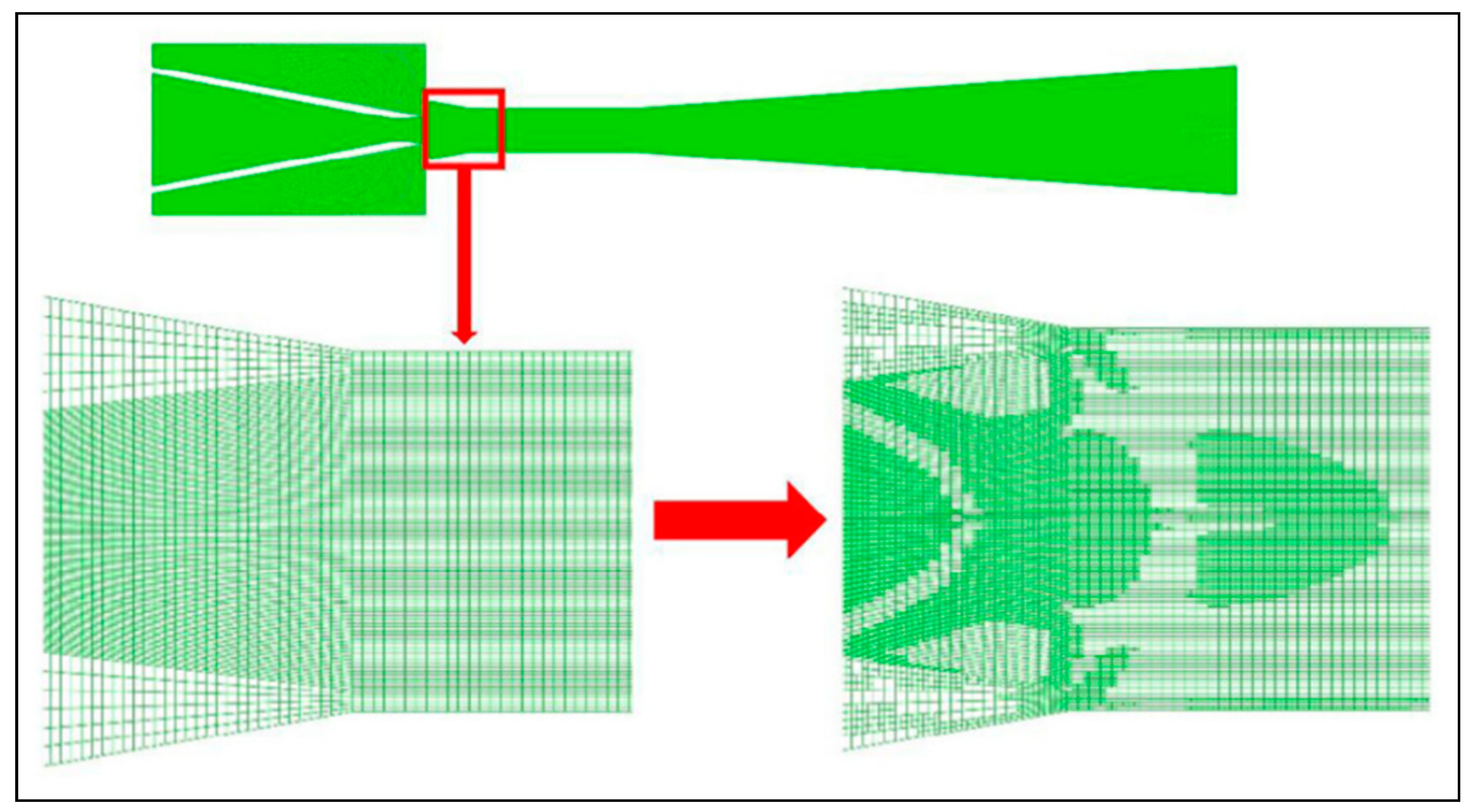
Many parameters need to be carefully selected for a successful simulation. The geometry modeling domain and often the available computational means dictate either the selection of 3D or the 2D axisymmetric approach [15,208,209,228,231]. In the case of Pianthong et al. [15] and Sharifi et al. [157] who compared wall pressure distribution along the ejector, there was no significant difference between both approaches. The authors stated that the design of the secondary inlet allowed reduced flow velocity at this point, making the 3D effect negligible.
In other instances with adequate means of calculation available and where ejector geometry and size dictate the selection, 2D-axisymmetric or 3D studies have shown differences, particularly for complex geometries [232,233,234]. Mazzelli et al. [209] found good agreement for an air-operated ejector, across all 2D and 3D models at on-design conditions. However, predictions at off-design conditions gave only reasonably reliable results with 3D models.

Mesh Sensitivity

Sensitivity to grid selection (or grid dependency) always has to be carefully assessed for a compromise between simulation quality and computational cost [15,36,88,216,229].
Grid refinement is necessary in order to capture complex mechanisms such as shocks, boundary layers interaction and mixing. Grid structure is important as well because of its effect on false diffusion, the impact of which is reduced by grid refinement. The results need to be grid independent in order to ensure they are reliable [134,135,136,215,217,235,236,237].
Approaches such as grid adaptation which refine grids by zones adjusts the mesh only in the zones of important gradients, for example close to walls (Figure 21 and Figure 22) or in zones of shear layer [28,88,92,165,238] or automatic adjustment dictated by specific criteria have been used [94,137,210,219,224].

Solvers

A CFD approach is based on solving the Navier–Stokes equations. The literature related to ejectors shows that the most common techniques used to solve these equations are the steady and unsteady Reynolds-averaged Navier–Stokes. The most commonly used solver for ejector studies is density-based, which couples between mass, momentum and energy conservation equations. It is well adapted to simulate compressible, supersonic flows but requires high computational cost and may be prone to some convergence weaknesses [205]. The pressure-based solver couples only mass and momentum equations and generally offers a simpler alternative with satisfactory results [229,239,240,241].

Computation and Discretization Schemes

Several discretization schemes are available in the CFD platforms ant their selection depends on the flow type, the grid and the solution method. A compromise is generally sought in terms the order of discretization and grid refinement [242].

Turbulence Modeling

In order to close the system of RANS equations, several turbulence models may be selected depending on the flow conditions. Table 3 shows some CFD studies available in the literature and details on turbulence models follows below. Note that the commercial code Fluent is used in the majority of the studies with the 2D-axisymetric formulation.
Frequently used models in ejector studies include the Standard k-ε model, due to its robustness but other models adapted to handle swirl and high pressure gradients, like RNG k-ε or realizable k-ε for separation/reattachment, recirculation and boundary layers under high adverse pressure gradients are common. The k-ω and its upgrade k-ω SST, designed to combine the strength of Standard k-ε away from the walls and k-ω close to the walls are sometimes preferred. The RSM model accounts for anisotropy in turbulent viscosity; it is applicable for swirl, rotation and important strain rates but comes with a high computing cost. In spite of the fact that many authors performed extensive comparisons of theses models with different refrigerants and conditions, turbulence model selection has so far not achieved a full consensus among researchers for their use in ejectors. Menter et al. [250,251] recommended k-ω SST for more stability when dealing with the interaction of primary and secondary flow mixing and wall treatment. By comparing the predictions of the RNG k-ε and RSM models, Riffat and Everitt [235] obtained equivalent results with steam in the same operating conditions. Desevaux et al. [134,135,252] compared axial pressure simulation with measurements in an air ejector with or without induced flow and concluded that Standard k-ε correctly reproduced their results. Al-ansary and Jeter [147,216] comparing Standard k-ε and RNG k-ε found this latter to better predict both the induced flow and the shock structure inside an air ejector.
Bartosiewicz et al. [210] compared predictions of turbulence models on air ejector and found large prediction differences between Standard k-ε, k-ω SST and k-ε RNG models. Further tests with R142b for the entrainment ratio were performed by Bartosiewicz et al. [218] using the same turbulence models and found large prediction differences, especially in off-design operation. Moreover the number of separations/reattachments of the boundary layer was observed to vary with the turbulence model selected (Figure 23). The authors attributed these differences to the discrepancy in shock-wave strength predictions by each model.
Hemidi et al. [242] use of Standard k-ε and k-ω SST models with air indicated that Standard k-ε model predicted both on-design and off-design experiments for entrainment and compression with less than 10% discrepancy.
Gawehn et al [243] compared simulations results using k-ω SST and RSM with wall pressure measurements and flow visualisations and found good agreement for the pressure but discrepancies in the flow structure.
Yang et al. [32] compared numerical predictions based on Standard k-ε, Realizable k-ε, RNG k-ε against the experimental data on steam generated by Sriveerakul et al. [88] and selected Realizable k-ε as the model best representing the experiments. By exploring ejector local features, using shadowgraph images, Little et al. [253] selected k-ω SST as model best representing their data.
Recognizing the important influence of nozzles outlet conditions on downstream flow in engineering applications, several other numerical studies were performed. Yu et al. [244] investigated the effect of nozzle configuration on turbulence characteristics of water flow in order to find out how the flow field changed with nozzle exit geometry. Four nozzle shapes (baseline, extended, grooved and ringed) were simulated numerically using different turbulence models out of which the RSM model was found to best represent experimental turbulent fluctuations data in terms of turbulence intensity, kinetic energy, dissipation rate and velocity. Yang et al. [32] were interested in the effect of nozzle geometry on the mixing process. Five geometries were numerically compared with steam to the baseline axisymmetric geometry. Three turbulence models (Standard k-ε, RNG k-ε and Realizable k-ε) were compared on the basis of experimental results by Sriveerakul et al. [88] for the reference axisymmetric case, on which they selected the Realizable k-ε turbulence model for their simulations. Kong et al. [34] also used steam in the context of desalination to numerically simulate the chevron nozzle, k-ω SST turbulent model was used in the computations. As previously mentioned, improvements were reported of 14.8% and 8.5% for entrainment and compression ratios, respectively, attributed to enhanced stream mixing. In references [69,229], Standard k-ε, Realizable k-ε, RNG k-ε, k-ω SST models were tested with N2 and air as working fluids, retaining RNG k-ε as the most appropriate for tested conditions. Gagan et al. [245] presented flow visualisation investigations by applying the particle image velocimetry (PIV) technique along with CFD modeling and recommended standard k-ε model as best representing their results.
Hakkaki-Fard et al. [211] shaped the primary nozzle by the method of characteristics in order to control the outlet flow at the mixing chamber inlet. The ejector was numerically simulated using R134a as the working fluid in the refrigeration context. The Standard k-ε turbulence model was selected. Simulations were performed for the same conditions in a reference ejector with conventional primary nozzle. Performance predictions in terms of entrainment and compression ratios for the new geometry were respectively over 20% higher and around 2% lower than for the conventional geometry operating in the same conditions.
Further work [203,209,234] under different conditions and fluids found SST k-ω to best represent their case studies.
Recently, Croquer et al. [247] compared the R134a experiments of García Del Valle et al. [48] against simulations using Standard k-ε, Realizable k-ε, RNG k-ε and the SST k-ω model in its high and low Reynolds versions. Even though the ejector performance in terms of entrainment and compression ratios was fairly reproduced by all these models, the internal flow structure was best reproduced only by the k-ω SST models. All in all the low Reynolds k-ω SST model was selected for predicting satisfactorily both performance and flow structure. However, Little and Garimella [254] and Zhang et al. [248] found RNG k-ε and k-ε formulations to better represent their findings for air and R134a, respectively.
Even more recently Han et al. [249] study the effect of stream boundary layer separation on ejector performance, under different throat diameters and NXP. Results showed k-ε realizable and k-ω SST turbulence models to better predict their experiments than standard k-ε and RNG k-ε models.
In any case, irrespective of the model type selected, the investigations mentioned above show that careful validation needs to be performed in order to ascertain the quality of the results generated.

7. Experimentation on Ejectors

Several experimental studies on ejectors are now available in the literature. A great number of them generated data in terms of global performance indicators such as inlet and outlet operational constraints (pressures, temperatures, flow rates) since the ejector is generally part of a system. This section refers only to this type of experiments with the main purpose to investigate the ejector in solo operation and generate global data. Other investigations, however, focused on local flow analysis using various experimental approaches and are discussed in a section dedicated to local data generation. The first purpose of the experiments on ejectors is to generate data for model validations, and information on its operation. In many instances the same data offers valuable information as well on ejector cycle operations but it is important to recall that optimal ejector operation does not necessarily result in optimal cycle operation. This aspect, scarcely discussed, has been observed experimentally by some researchers [255,256]. In any case and irrespective of the objective of data collection, one of the key elements is the working fluid selection. A representative sample of the experimental analyses and information currently available in the literature of steam and organic refrigerants, respectively.

7.1. Working Fluids

Ejectors are very sensitive to the working fluids in terms of operation and performance. Dry refrigerants (saturation curve skewed right in Figure 24) are preferred to wet ones in this respect because they do not condense when they expand in the primary nozzle. Condensation can be avoided in wet refrigerants by providing limited superheat but this somewhat affects performance. In a refrigeration cycle, and depending on the fluid type, the amount of superheat needs, therefore, to be maintained within reasonable limits, so as not to waste energy and reduce cycle COP.
Favourable thermo-physical properties to ensure high performance in the range of intended use is of primary importance. In addition to thermodynamic considerations, selection criteria of the working fluid include, however, at least considerations such as environmental preservation, safety issues, availability and costs in addition to the primary requirement of performance.
The efficiency of the system as a whole is conditioned by favourable thermophysical properties of the refrigerant selected for the range of intended operation. Properties such as latent heat of evaporation, specific heat, viscosity, thermal conductivity, specific volume, normal boiling and critical points all play an important role in ejector operation and overall cycle performance.
For example, the working fluid must have favourable heat transfer properties, like specific heat, viscosity and thermal conductivity for heat exchange efficiency and overall performance of the cycle. In order to be able to use low-grade thermal energy, low boiling temperatures are desired as well. In general, a high specific volume increases the ejector size and high molecular weight favours the ejector entrainment ratio but may also reduce size. A high latent heat of evaporation and a wide generator temperature range reduce the specific circulation rate.
Ejector operating flexibility and performance depend on boiling, condensation and critical points. For given operating conditions, the boiling point influences the suction pressure from the evaporator to which ejector performance is generally sensitive. Whenever possible, this pressure should be above atmospheric to prevent infiltration from the ambient and the condenser pressure should not be too high to avoid unnecessarily expensive equipment. A high critical point offers flexibility on the generator side in terms of temperature variations. Corresponding pressures should not, however, be too high in order to avoid building a heavy (and costly) pressure vessel, beside an excessive energy consumption of the refrigerant pump.
For interested readers, this topic was covered in more detail in previous reviews [5,8,9]. Theoretical and experimental fluid evaluations found in the literature for use in ejectors were performed to identify the most appropriate fluid for a chosen working range of conditions. Earlier studies used air and water (Table 4) but also synthetic refrigerants (Table 5) of CFC, HCFC and HFC types, including their mixtures.
Sun [257] classified several refrigerants from different types (water, CFCs, HCFCs, HFCs, RC318 and R500) on the basis of the COP of a conventional ejector cycle under the same conditions. R152a was found to offer the highest performance. It was further observed that varying the operating conditions did not alter the refrigerant classification. Other researchers [46,193,258] focused their interest on the performance of azeotropic and zeotropic mixtures obtained by mixing two or more pure refrigerants in various proportions. They analysed a variety of pure refrigerants and mixtures of hydrocarbons, HCFCs and HFCs. Azeotropic mixtures were found generally to perform better than their components. In comparison with pure fluids, they observed that slightly zeotropic or quasi-azeotropic mixtures improved the COP, contrary to the strongly zeotropic mixtures. Adopting a similar procedure and using the area ratio φ as a parameter, Cizungu et al. [259] evaluated R123, R134a, R152a, and R717 on the basis of the entrainment ratio ω and the cycle COP for different operating conditions. In the temperature range 70 ≤ Tg ≤ 85 °C, ammonia was found to provide the highest performance. Later research by Selvaraju and Mani [187,260] could achieve higher performance in terms of ω and COP with R134a among the refrigerants considered, which were R134a, R152a, R290, R600a and R717.
Air was, and is still often used for validation works since it is less costly to model and test but has little potential for use as a refrigerant in applications. Water was used in the past in ejectors for positive cooling by use of costly steam (high quality). For heat recovery at low temperatures for steam, ejector performance is poor and equipment are large. It is, however, still current in research for its flexibility and familiarity of use. It was common to model both fluids and other refrigerants as perfect gases or determine their properties by means of equations of state from the literature [63,192,193] and many others. Databases such as EES (Engineering Equation Solver) or NIST-REFPROP later became available to this purpose [41,265,266].
More recent research focused on natural fluids such as CO2, hydrocarbons and hydrofluoroolefins (HFOs). Increasing interest in these fluids is supported by their performance potential and their innocuous character to the environment [264,267,268,269,270]. Carbon dioxide has promising features despite a very low critical temperature and a high critical pressure, therefore needing further work on ways to alleviate costs related to its implementation. Hydrocarbons, HFOs are promising and require further characterization and hands-on information [271,272,273,274].
Another promising avenue in terms of refrigerants is the introduction of nano fluids, which are attracting increased interest for their potential benefits in ERS applications. From the point of view of heat transfer and flow boiling, the evaporator is expected to work under favourable conditions of high pressures and low temperature differences with an overall cycle performance improvement.
A theoretical assessment performed by Tashtoush et al. [275] predicted a COP increase of 24.7% for R134a-CuO and 12.61% for R134a-Al2O3 mixtures, respectively.

7.2. Parameters Measurements

Ejector performance indicators are the entrainment and compression ratios, as previously defined. In addition, pressures and temperatures at the inlets and outlet are also needed. Early data was gathered for cooling and refrigeration with water and progressively with other refrigerants. For validation needs, global variable and parameter measurements such as pressures, temperatures and mass flow rates are collected at strategic locations, particularly at the ejector inlets and outlet. The data gathered in this way is all that is generally needed to qualify the ejector in terms of its two main performance criteria, the entrainment and pressure ratios. Analytical model development makes use of these data and associated operational information for validation and preliminary design purposes. For numerical model developments, in addition to global data, local parameter measurements and information are needed as well. Static wall pressure distribution along the ejector is relatively easy to measure without disturbing the flow. Less frequently, centre line static pressure distribution was also measured at the expense of some flow disturbance. Experimental information on local flow structure requires recourse to various visualization techniques, generally more complex and costly than capturing pressure distributions. In view of their importance, parameter measurement issues are discussed in more detail in the following sections.

7.3. Data for Model Validations

As already pointed out, early ejector models were based on integral conservation equations, thermodynamic considerations and sometimes empirical procedures. They usually relied on many simplifying assumptions and used coefficients to account for friction and mixing losses. Later, CFD simulations were performed without relying on so many simplifying assumptions, but requiring for their validation both global and local measurements, which are still scarce for covering most situations of interest. For this reason, the experimental validation of the models is very important for all types of models. However, data availability has been relatively limited and many modeling works relied on the literature for comparisons and performed qualitative studies.
The theoretical and numerical work reported in the present document is supported by experimental information and data for the validation of the predictive models (design and simulation) as well as for confirming local flow behaviour and internal structure.

7.3.1. Global Validation

Where possible, most ejector modeling has been validated by comparison with experiments focused on global data in terms of pressures, temperatures and flow rates [58,94,136,169,217,219,237,276,277] to name only a few. Several comparisons between simulation and experiments were performed and discrepancies were generally fair (5% to 15% approximately) for analytical modeling [59,70,278]. However early numerical predictions were less favourable, the possible reason being that the models did not correctly handle shock wave occurrence and shear layer [235]. Progress in computational power and CFD developments in recent years have improved a great deal the agreement between simulations and experiments. Rusly et al. [72] simulated on-design operation of ejectors based on Huang et al. [70] results for R141b with remarkable success (less than 3.5% discrepancy on ω). Recent comparisons with various refrigerants and conditions were performed by many authors [15,78,88,92,158,203,230,238] with fairly good predictions for ω and outlet pressure in the respective ranges of (5–24%) and (7–11%).

7.3.2. Local Validation

Pressure Distribution

Local data for ejectors is relatively scarce, due to the inherent difficulty of measurement in a confined environment and restricted geometry sizes, typical of these components. Static pressure distribution has been one focus of interest in order to collect information about the ‘shape’ of the recompression process, given the operating conditions. Measurements were made by many researchers with different refrigerants and conditions of operation [49,52,60,88,112,118,141,211] giving the profile of local pressure distribution particularly in the nozzle outlet zone and along the mixing chamber. This information is used to validate models and optimise geometries [75,277]. The pressure profile is often drawn from pressure points distributed on the wall along the mixing chamber length. This technique is obviously limited in that wall pressure may not always represent the main flow because the mixing process is not uniform along the mixing chamber and the number of data points is insufficient for a reliable pressure profile [237]. A Pitot tube was used by Al-Doori [279] in the mixing zone to monitor the radial change of pressure, particularly in the shear flow zone between the primary and secondary streams. The author provided, however, no information on the potential disturbance of the flow by this method.
Desevaux et al. [217,237] generated additional pressure distribution data but they were limited to air as a working fluid. Their method consisted in sliding a mobile capillary tube along the ejector axis. The results obtained by this method allowed the recompression process in the mixing chamber to be followed and compared favourably with the visualization of the shock structures [210]. This system, however, may interact with the flow and modify its internal structure.

Flow Visualization

Ejector flow physics complexity has been the main limitation for the development of accurate and reliable predictive modeling of ejectors. Among the reasons are the lack of local data and flow visualisation other than air or steam. Models based on integral conservation equations build on many assumptions requiring validation. CFD powerful prediction capabilities still do not achieve a full consensus about ejector flow effects and structure. For this reason, visualization techniques become increasingly necessary as means of model validation. Early visualization studies have been scarce and were limited to air or steam. They used the Schlieren technique to detect changes in the refractive index of fluids of different densities. Keenan et al. [12] captured sharp images of shock waves at the primary nozzle outlet, as well as streamlines of suction flow for several outlet pressures. Different studies [134,135,217,237,280] performed similar work, visualizing shock formation in the nozzle and the diffuser.
Chen and Sun [60] conducted experiments with steam to generate data in a range suitable for moderate cooling, which allowed them to construct operating maps. Preliminary observation results were discussed. They recorded an axial wall pressure distribution at three different backpressures and relying on typical Schlieren imaging produced on an air ejector, which they considered as a good indication of the flow field in a steam ejector, they drew a schematic representation of their flow structure.
Zare-Behtash et al. [281] applied the technique of visualization on an ejector motive jet for thrust augmentation applications. Little et al. [253] compared shadowgraph imaging for air with CFD predictions and Zhu and Jiang [228,229] investigated the shock wave structures in a three-dimensional ejector by CFD and the Schlieren visualization (Figure 25). They estimated the length of the first shock cell at the exit of the primary nozzle so as did Rao and Jagadeesh [109] in the study of unsteady shock motion in an ejector working in the off-design regime.
Tomography techniques based on the laser sheet method were employed to study mixing phenomena [282]. Bouhanguel [107] further used laser tomography to visualise the air flow inside the ejector and investigate velocity by image velocimetry for CFD validations. By means of this technique, the authors were able to highlight the non-mixing zone. Visualization was used as well for internal iso-Mach comparisons generated by simulation, mainly in the shock wave zones located generally behind the primary nozzle exit, before the diffuser inlet and along the second throat [134]. In this latter case color tracers were used in simulations [210,237]. The tomography technique was adapted to measure velocity in a supersonic ejector by PIV and the results were reported in [107,283,284]. However, the light intensity of the tracer particles used is not always high enough for clear pictures, particularly with high suction flows which reduce the light intensity of tracer particles. The method showed the motive jet shape satisfactorily but compression-expansion waves were less clear. Dvorak and Kotek [285], conducted PIV measurements for constant area mixing in a subsonic air ejector. The velocity fields were taken for four different mixing regimes, each with different ejection ratios. Further visualization work was performed by Rao and Jagadeesh [109] with air by combining Schlieren and laser-scattering images to characterize mixing and shock-cell formation. The potential of visualization techniques is high for better understanding of the ejector local structure but more fluids other than air need to be explored to this end. Along this path, recent work by Little and Garimella [254] using the shadowgraph visualization enabled a direct observation of the R134a flow dynamics through an ejector operating under conditions of a chiller system. The authors used high-speed imaging with measured temperatures and pressures at the ejector inlets for validation purposes.

8. Recent Ejector Refrigeration Systems (ERS) Studies

Ejector-based refrigeration systems combine the Rankine cycle and the gas dynamics effect of the ejector through a thermal compression process. A remarkable feature of such systems is their minimal electricity consumption, which generally results in a substantial gain of efficiency for the whole cycle. The ejector itself is low cost, relatively simple with no moving parts and highly reliable. However, ejectors are characterized by low thermodynamic efficiency, resulting in modest values of cycle COP. For this reason, cycles using renewable energy with internal heat recovery in combination with other refrigeration technologies are thought to be most promising. Ejectors can be activated by almost any low-quality heat source (waste heat, energy from biomass, solar, ground) and since there is no need for lubrication, nearly any working fluid may be used. In addition, ERS may integrate one or more ejectors operating in a jet pump. The simplest configuration is the conventional ejector refrigeration cycle shown in Figure 26. However, diverse cycle variations with different degrees of complexity are categorized in the literature as advanced, combined, and ejector hybrid refrigeration systems.
A rough classification of the gas ejector used in refrigeration is shown in Figure 27. Several prominent reviews have been dedicated to their description up to 2016 [3,5,7,8,9,286] as briefly discussed in the introduction of the present paper. Since the main focus here revolves about the ejector as the heart of any system, only highlights of earlier representative systems or those having received little attention will be reported, in addition to the most important contributions recently published.

8.1. Conventional ERS

This system has been intensively studied and continues to be the focus of many investigations in view of its simplicity. For interested readers, further details can be found in [48,57,59,273] and many others.
Figure 26 depicts a conventional cycle based on this concept commonly found in the literature and tested by many researchers for compressor replacement in refrigeration systems.
For a refrigeration cycle which is the purpose here, operating in the context cold production and given external constraints, the thermal coefficient of performance is a function of the entrainment ratio ω, such that:
COP th = ω Q e Q e + W pu ,
And its mechanical equivalent is expressed as:
COP me = ω Q e W pu ,
where Qe and Wpu are specific heats and mechanical work transferred during the process. It is obvious that the higher ω is, the better will be the cycle performance. This explains why ejector performance maps are often drawn in terms of optimal operating conditions as shown by Figure 12.
The majority of studies seeking to optimise ERS cycles rely on laws of thermodynamics, exergoeconomics and other energy-based methods. Combining exergy considerations with the conventional concepts of engineering economics, they evaluate and optimize the design, performance and cost of energy systems by means of multi-objective procedures but fail to tackle environmental problems [168,287,288,289] to cite only a few. Performance is not the only criterion to decide on whether or not to use ejectors; factors such as availability, cost and environmental impact should also be considered. In recent decades, the environment and its preservation have become a global issue. Life-cycle assessment (LCA) is a common tool to evaluate the overall environmental impacts of a process. LCA analyses the energy and materials employed in all stages of the entire useful life of the process, from materials supply, production, transport, energy generation to decommissioning. LCA methods have been progressing for the last decades, using ecological and energy indicators to assess the environmental impact of refrigeration systems. The LCA approach may typically be employed in the analysis of various environmental impacts, ranging from greenhouse warming potential to ozone depletion potential and more [220]. Little, however, can be found in the literature regarding the environmental impacts of the life cycle for ejector applications. Grazzini and Rocchetti [290] presented a numerical optimisation of a steam ejector cycle. The authors employed different objective functions as optimisation criteria, and one of them was based on the LCA approach. In another application context of power-intensive equipment integrating ejectors, this methodology of eco-energy analysis based on the calculation of the life-cycle greenhouse gas emissions, was proposed by Chen et al. [220]. A synthetic fluid (HFC) R245fa and a natural refrigerant R600a were analysed under different working conditions in China and Ukraine. New eco-energy indicators were developed, showing that ejector air conditioners have eco-energy prospects for implementation if they are driven by waste heat abundantly generated by several industries.

8.1.1. Conventional ERS Theoretical Studies

One common issue to ERS and other related refrigeration system configurations is the component interaction, particularly between the ejector and the heat exchangers (generator, condenser, and evaporator) in other cases with the compressor. Some studies have shown that the behaviour and performance of an ejector cycle largely depended on ejector design and operating conditions, but there was room for improvement in internal cycle losses including throttling and component mismatching within the cycle. Correct insertion of an ejector in a refrigeration cycle is part of an optimization procedure, however may require little additional hardware and minimal cost. Earlier work along these lines was proposed by Dahmani et al. [291], with a design methodology for ERS of fixed cooling capacity, operating with fixed temperatures of the external fluids entering the generator. The condenser and the evaporator were applied to a particular combination of operating parameters. The results established the existence of optimal values for the refrigerant pressure in the generator and the temperature difference in the heat exchangers which minimized the total thermal conductance of the system. These optimal pressure and temperature differences, determined for four refrigerants (R134a, R152a, R290 and R600a), yielded high values for the coefficient of performance and the exergy efficiency of the system. Several approaches of energy and exergy analysis based on the first and second laws and finite thermodynamics were proposed to handle losses in terms of exergy destruction in different parts of the ERS. The level of detail ranged from the loss distribution in different parts of the system to reflecting the effect of interactions between constitutive components [292].
Thongtip and Aphornratana [62] pointed out that the effect of the generator pressure on evaporator temperature and other parameters, needed to be further investigated in order to have a more accurate picture of the different interactions between operating parameters. Indeed, in the current literature and since the work of Dahmani et al. [291] information on mutual interaction between governing parameters and the effect of external boundary conditions is still scarce.
Hernandez et al. [293] revisited the effect of refrigerants, given the operating conditions. Thermodynamic simulation cases for ERS cooling applications comparing R410A and R507 in critical operation were conducted and found by the authors to be suitable options for Tg = 50–70 °C, Tc = 30–40 °C and Te = 5–15 °C.
The refrigerant issue was also the subject of further investigations since ERS performance is very sensitive to the working fluid. In this respect, Buyadgie et al. [294] proposed the use of binary and multi-component fluids. According to the authors’ theoretical evaluation, such a system significantly increases system COP and has the additional advantage of improved off-design efficiency in comparison to a conventional ERS under similar conditions. This system, however, has not been proven in practice, perhaps due to its complexity in terms of number of components, controls and fractionation issues.
A recent study by Fang et al. [271] relates to the search for a HFO drop-in refrigerants for an ERS using R134a as working fluid. R1234yf, R1234ze as well as mixtures with R134a-1234yf in proportions 20–80% and 80–20%. Ejector performance showed a slight decrease of the entrainment ratio (≈−5%) and COP (≈10%) for R1234yf and (≈3.5 %) and COP (≈4.2 %) for R1234yf. In all scenarios R134a has always shown the highest performance.
Given the substantial availability of solar energy, a considerable low temperature thermal source, it can indeed be exploited to energize ejector based refrigeration or heat pumping systems. In warm climates with abundant sunny periods, efficient solar collectors can drive ejector-based systems for air conditioning and energy storage for heat pumping. An important analytical effort has already been invested by many researchers to investigate the implementation of solar energy to drive ejector-based refrigerators. Sokolov and Hershgal [295] studied the performance of an ejector solar system using R114 as the working fluid and highlighted the potential gain in performance that could be achieved. Huang et al. [296] performed an analytical study to implement solar energy in a jet-pump refrigeration system with R141b, and Alexis and Karayiannis [117] considered a solar cooling system with R134a for the Athens conditions. Ongoing development work on solar-powered ejector-based air-conditioning systems for residential use continues to be promising to achieve cost-effective ejector-based units [148]. Analysis of a solar-assisted ejector cooling system with cold storage was conducted by [297]. Simulations were carried out over one year considering climatic data for a hot location (Béchar, Algeria) and the performance of the system was assessed for a set of design conditions. Effects of cold storage upon comfort conditions and energy demand were evaluated. Maximum room temperature and overall interval of time during which the room temperature exceeded the set-point value were the parameters used to quantify system performance. It was found that cold storage improved comfort conditions compared to a system without storage. A further energy analysis was proposed by Diaconu [298] on a solar-activated ERS with low energy storage, applied to an office building. Recent research is now increasingly focusing on experimental applications.
Redo and Berana [299] theoretically studied the potential of ERS activated by geothermal energy for cooling in hot and humid climates. The range of 60 °C to 100 °C available geothermal fluid temperature was used with R717 and R134a to produce a cooling effect in the range 8 to 25 °C at a fixed condensing temperature of 40 °C. A similar study combining ERS and an ORC (organic Rankine cycle) activated by geothermal energy for simultaneous refrigeration and power was proposed by [300]. R245fa was selected as the working fluid and the preliminary system design was set for a cooling load of 153.7 kW and a power output of 101.79 kW.
Sadeghi et al. [288] assessed an automotive application of ejector air-conditioner system powered by waste heat from exhaust gases engine. Relying on exergo-economic considerations and multi-objective optimization, in order to minimize overall cost and maximise performance, they assessed automobile cooling ejector application using exhaust waste heat. They concluded that optimal operating conditions for this system would correspond to the generator, the condenser and the evaporator working respectively at 94.54 °C, 33.44 °C and 0.03 °C.

8.1.2. Conventional ERS Experimental Studies

Eames [73] demonstrated the feasibility of a 1.5 kW capacity conventional ejector cycle for air conditioning. Refrigerant R245fa was the working fluid and COP values achieved were of the order of 0.25-0.7. Allouche et al. [301] presented the preliminary results of a solar-driven ejector refrigeration system for air-conditioning in the Mediterranean climate. The installation was a 5 kW single stage solar-driven ejector set-up. Solar-evacuated tubes were used for the generator, an ice-slurry using micro-encapsulated phase change material was employed for energy storage, a 7 kW auxiliary heating source and a 10 kW condenser completed the system. Unfortunately the authors did not provide the details on the temperature levels, the conditions and duration of the experiments or the system’s overall performance.
Another issue of major concern is the selection of the working fluids which not only should be environmentally innocuous but at the same time favour high ejector performance. Two papers were published respectively by [118,268] both using isobutane. The authors conducted experiments on a solar-activated ejector system at generating temperatures below 80 °C. In fact they could effectively operate their set-up in the following ranges of temperatures: 55 °C ≤ Tg ≤ 80 °C; 3.5 °C ≤ Te ≤ 7 °C; 25 °C ≤ Tc ≤ 31 °C. The COP in these ranges of temperatures varied approximately between 0.15 and 0.20. Primary and secondary streams were slightly superheated, respectively 8 °C and 6.5 °C. The authors pointed out that at such low activation temperatures, the absorption technology was no longer competitive with ejectors.
Mazzelli and Milazzo [165] analysed theoretically and experimentally an ejector-based industrial chiller using R245fa of 40 kW capacity and powered by low temperature heat in the range of 90 °C up to 100 °C. Investigations were performed satisfactorily in both on-design and off-design conditions. This work was extended by Milazzo and Rocchetti [302] to other fluids (water, isobutane, 5 HFCs and 3 HFOs) whose performance was calculated on a wide range of heat source/sink temperatures. The authors mention that poor results usually associated with steam may be argued and HFO1233zd gave good results.
Zegenhagen and Ziegler [255] recent work on conventional ERS was designed to study the influence of boundary conditions on system performance. They carried out experiments for automotive applications with refrigerant R134a in an ERS of 6 kW cooling capacity. The data generated allowed them to correlate thermodynamic and mechanical coefficients of performance, as well as the cooling capacity as a function of the entrainment ratio and generating pressure. They produced an operation map of the jet pump set-up, run with changing boundary conditions. The test conditions were in the following ranges: 2.55 MPa ≤ Pg ≤ 4.15 MPa; 350.15 K ≤ Tg ≤ 380.15 K; 0.54 MPa ≤ Pc ≤ 0.97 MPa; 291.15 K ≤ Tc ≤ 311.15 K; 0.15 MPa ≤ Pe ≤ 0.4 MPa; 258.15 K ≤ Te ≤ 283.15 K.
More recently, Śmierciew et al. [272] experimented with a new refrigerant, HFO-1234ze(E) in a range of activation temperatures, i.e., 53.4 °C ≤ Tg ≤ 56.5 °C on a pilot scale system for refrigeration. In this case the refrigeration capacity varied between 10 and 36 kW approximately. Condensation and evaporation temperatures at saturation conditions varied respectively in the ranges 18–30.2 °C and −6.7 to −12.5 °C. It appears from these results that the amount of superheat is not negligible and unfortunately this aspect was not sufficiently commented in the paper.
In the wake of the works of [62,199,255], Hamzaoui et al. [256] aligned their research with the objective of ejector operation in an ERS context. Their experiments were based on ERS prototype using R245fa as a working medium which is illustrated in Figure 28. This system was designed with a nominal capacity of 35 kW at an evaporating temperature of 15 °C, corresponding to R245fa boiling point at normal conditions. The main objective of their study was to investigate the interaction between governing parameters, namely the effect of generating pressure on condensing and evaporating pressures as well as the relation with ejector operation. The data generated under various conditions were used to map system operation in terms of conventional performance parameters used in refrigeration systems integrating a supersonic ejector. The maps provide design guidelines under real conditions of operation for an optimal ejector-based system performance operating in the range of cooling conditions covered by the experiments.
Typical ERS relevant studies are summarized in Table 6.

8.2. Ejector Combinations with Conventional Technologies

Despite the ERS attractive features of simplicity, reliability and costs its performance is relatively modest and many other ejector-based cycle configurations have been investigated by researchers. Some configurations having not received sufficient attention and some more recent ones are reported below to illustrate their main features.
Ejector combinations with various existing technologies such as solar, absorption or compression forming hybrids, cascades and other cycle configurations have the potential to enhance performance substantially. Careful ejector integration into industrial systems and processes may provide interesting opportunities for cycle optimization. Combined ejector-absorption and ejector-compressor cycles systems have received a great deal of attention for their positive impact on performance in exchange of relatively minor modifications to the overall set-up. In this respect, several configurations have been explored theoretically and experimentally to improve ejector-based system efficiency through the use of economizers and heat-recovery devices in combination with booster systems.
References [9,45,286,303] cover most of the available theoretical and experimental work, ranging from mathematical modeling to refrigeration applications based on compressor–ejector coupling or solar-activated ejector combinations. Subsequent theoretical investigations along the path of ERS and organic Rankine cycle combinations were undertaken by many researchers in a variety of conditions regarding the activation source (solar, waste heat), heat storage, working fluids and mixtures [289,304,305,306,307,308].

8.2.1. Combined ERS Theoretical Studies

Ejector–compressor combinations to form boosters and cascades for refrigeration (Figure 29) have been the subject of many evaluations. Early works by [309,310,311,312] are worth mentioning. Sokolov and his collaborators demonstrated that performances comparable to those of absorption systems could be attained with booster-assisted ejector cycles running on low grade and solar heat. Depending on the particular operating conditions and cycle configurations, reported COP improvements ranged from 5% to 40% over conventional cycles. For example, Dorantès and Lallemand [258] mathematically simulated such a solar-powered ejector–compression unit with thermal storage for ice production. They reported annual average values for COP, collector and system efficiencies of 0.21, 0.52 and 0.11 respectively with R142b as the working fluid for the climatic conditions of Morelos state in Mexico.
Still in the context of a solar application where the irradiation intensity is highly variable, Dennis et al. [313] designed an algorithm accounting for the behaviour of the solar collector and the vapour generator to adjust the nozzle geometry of VGE accordingly for system performance optimization. Allouche et al. [314] developed a dynamic simulation of the integrated solar-driven ejector cooling system including a PCM (phase change materials)-based storage unit. Effects of varying solar collector area size, hot storage capacity and cold storage were investigated. With no cold storage the comfort temperature was exceeded more than 26% of the time. With cold storage the periods of high indoor temperatures were significantly reduced.
Ben Mansour et al. [315] theoretically evaluated three different ejector-assisted mechanical compression systems for refrigeration applications (Figure 29), which they compared with conventional compression cycles working under comparable conditions. Recognizing that the components making any ejector-based refrigeration cycle do not operate in solo but their optimal operation is a result of mutual interaction, they developed a methodology handling the coupled ejection and compression loops forming such systems in constant ejector–compressor interaction. A performance analysis and a parametric optimization based on ejector modeling and compressor performance maps showed that substantial improvement in performance of the selected cycles could be found. This approach was extended to study the potential application of these combined cycles to low temperature heat pumps [315]. The study used R134a as a working fluid and showed that hybrid ejector–compressor and cascade cycles were promising with a high potential for substantial performance improvements in cold climate conditions. Prediction results indicated that cases (a) and (c) were respectively 21% and 40% potentially more performing than the conventional compression heat pump.
Xue et al. [316] analysed a combined cascade ERS similar to the cycle of Figure 29b, driven by low-grade energy with R134a. The study focused on system modeling for real-time system control, accounting for the heat exchangers dynamics and the static properties of the compressor, the ejector and the expansion valve.
The new cycle proposed by Xu et al. [317] differs from the conventional hybrid mechanical–thermal ejector cycle commonly described in the literature [155,312,315] and many others by the addition of a second expansion valve and a separator to the system (Figure 30). The separator is inserted immediately after the first expansion valve after the condenser. The separator receives two-phase condensate at an intermediate pressure. Vapour is drawn to the ejector suction and the liquid is further expanded to the evaporator conditions, then drawn by the compressor. Both compressor and ejector return the compressed refrigerant to the condenser inlet conditions to complete the cycle. Preliminary performance estimates of the new solar-assisted cycle based on R152a indicate a COP improvement of 22.8% over the conventional hybrid cycle.
In the context of air conditioning conditions, Expósito Carrillo et al. [318] compared a number of combined ERS cycles (hybrid, multi-stage, cascade, booster with economiser, with both ejectors jet pumps and gas ejectors). Evaluation of the refrigerants R134a, R1234yf and R600a led to the selection of R600a with expected performance improvements in the order of 26% for the ejector expansion refrigeration cycle.
A further example was proposed by Tan et al. [319] in the form of an auto-cascade assembly working with a mixture of R32/R236fa (Figure 31). The system is similar to a conventional ERS with a flash tank inserted after the condenser separating the mixture into condensate (R236fa) feeding the generator and a first evaporator. The non-condensed vapor (R32) is redirected to a second evaporator after condensing in an evaporative condenser in the form of internal heat recovery. Theoretically, the authors estimated the system to deliver low evaporation temperatures, but COP was very modest (≈5%).
Ejector-boosted absorption is another area where substantial COP improvements are expected by enhancing evaporation, absorption and concentration processes and by carefully selecting the refrigerant. Several studies mostly theoretical, were previously conducted on absorption cycles integrating ejectors. Typically the works of [116,194,320,321,322] are well documented.
The work of Hong et al. [323] analysed an ejector application combined with a double-effect absorption cycle (Figure 32) in order to operate as ejector-boosted single effect when the available activation heat temperature is not sufficiently high. Under such conditions the ejector-boosted cycle is estimated to be up to 30% more efficient than single-effect absorption.
Khaliq et al. [287] evaluated the exergy distribution of a waste heat activated absorption-ejector refrigeration cycle (LiBr-H2O and R141b respectively) from the first and second law efficiency perspective, along with the exergy destruction in its various components.
Efficiency improvement of a similar cycle combining a LiBr-H2O absorption and an ERS powered by renewable energy was later conducted by Kumar and Kumar [324] on the basis of an energy and exergy approach. It was concluded that coupling a well designed jet pump with a conventional absorption system favourably affected exergy and energy efficiencies.
Similarly, a cooling system operating with the LiBr-H2O working pair, driven at high temperature by parabolic trough solar collectors is proposed by Bellos and Tzivanidis [325]. The objective of the parametric analysis performed by the authors was to maximize system performance in terms of primary temperature and pressure, as well as the pressure drop in the ejector. This study generated results indicating that an optimized ejector-absorption system performance could be enhanced by up to 60.9% compared to the conventional absorption system at 12.5 °C evaporation and 30 °C condensation temperature conditions.
Sirwan et al. [326] investigated a solar activated ejector-absorption system consisting of a combined cycle using aqua-ammonia (NH3–H2O) as the working pair and including a flash tank in the ejector loop in order to extend its range of efficient operation. Simulations indicated improved overall COP, enhanced cooling capacity, better ejector performance and higher condenser pressure.
Further modification to the NH3/H2O absorption heat pump proposed by Abed et al. [327] consisted in integrating an ejector between the rectifier and the condenser (Figure 33) and adding a refrigerant heat exchanger between the condenser and the evaporator. The results of this analysis predicted an overall system performance improvement of approximately 12.2% over a conventional ammonia-water heat pump.
Theoretical investigations of ejector applications in chillers and air-conditioners were suggested for application in tri-generation systems by Petrenko et al. [148,328]. The authors consider that refrigerants such as R245fa, R245ca, R600 and R600a are the most suitable for applications in combined heat and power (CHP) systems with reciprocating engines, fuel cells, micro gas turbines and natural gas transportation, which all release substantial waste heat to the environment.
The ejector-CHP system of Figure 34 was proposed and analysed by Sun et al. [329]. In this particular case, waste heat district heating system with CHP, based on ejector heat exchangers and absorption heat pumps was compared with a conventional district heating system with CHP. The ejector set-up was activated by steam exhausted from a steam turbine and according to the analysis proposed by the authors, the steam consumption could decrease by 41.4% and heat transmission capacity increase by 66.7% without changing the flow rate of circulating water in the network. Recent research includes the works by [330,331] who proposed to combine ERC and Kalina cycle concepts for cooling and power generation. Other ejector studies in specific contexts of industrial applications are available in the literature. For example, Alexis [332] discussed the potential of energy conservation in co-generation systems. In this application, a 2 MW Rankine cycle produces electrical power and steam is bleeded off the turbine for heating in the winter or cooling by means of the ejector in the summer.
Liu et al. [333] on the other hand modified the conventional ERS by introducing a flash tank and an auxiliary ejector (Figure 35) to improve the performance. The main ejector entrains the vapor (secondary fluid) from the evaporator and the auxiliary ejector entrains the vapor (secondary fluid) from the flash tank. The combined stream from both the main and auxiliary ejector flows to the condenser, where it is condensed. Part of the condensate is pumped back to the generator, the remainder is expanded to an intermediate flash tank pressure. Vapour is extracted from the flash tank by the auxiliary ejector and the liquid is further expanded to the evaporator pressure feeding the primary ejector suction. Both ejectors reject the overall vapour flow at the pressure of the common condenser, thus completing the cycle. This modification to the cycle improved COP with R134a and R600a by 10.7% and 9.9%, respectively, over the conventional ERS configuration.
Many researchers considered for automotive applications, an ejector system as sub-cooling loop in a conventional mechanical refrigeration system. In this respect, Chen et al. [334] investigated the potential of a hybrid ERS and CO2-vapor compression for vehicle and road transport cooling, powered by exhaust gases. The ejector loop contributes to sub-cool CO2 in the compression loop, resulting in 22% performance improvement.
Recent work by Chen et al. [172] provided general guidelines on the optimised selection of one and two-stage ejectors. According to the authors’ findings, at on-design, one stage ejectors are more efficient than two-stage ones for low expansion ratios, while these latter are more suitable for high compression ratios.
Hao et al. [335] considered the use of mixtures of refrigerants in the evaluation of thermodynamic performance of HACRS (hybrid auto-cascade refrigeration system) based on R170/R600a which was then compared with ACRC (conventional auto-cascade refrigeration cycle). At the same evaporation temperature, the COP of HACRS is typically over 1.6 higher than that of ACRC.
Some authors worked on special cycle cases in an attempt to reduce stream mixing losses in the ejector and the parasitic energy consumption of the pump. An example is the work of Subramanian et al. [336] who investigated the concept of increasing the velocity of the secondary stream at the ejector inlet by means of a blower. Such a concept can be employed in engineering applications such as the downdraught gasifier system, the “venturi-scrubber” or “ejector venturi-scrubber” devices. The purpose was to reduce stream momentum difference during mixing and in turn minimize kinetic energy losses and examine the changes in operating parameters by means of proposed correlations.

8.2.2. Combined ERS Experimental Studies

In many instances of mechanical refrigeration installations, condensate sub-cooling is very common practice in order to increase performance. On the other hand, superheat at the compressor discharge can become very important. Depending on the type of refrigerant and the application, the vapor temperature may increase rapidly with compression. Instead of rejecting compression heat to the environment, it is recovered to activate an ERS acting as a sub-cooling loop in a conventional mechanical compression refrigerator. Early analysis of this case by Huang et al. [337] predicted a COP increase in the range of 9% to 24%. A variant of this system which consists in a combined ejector–vapor compression cycle (EVCC) using R134a as working fluid and air-cooled condensers for both sub-cycles was tested by Yan et al. [155] (shown in Figure 36). In this system, the ejector sub-cycle is used for sub-cooling the compressor loop, thereby enhancing the overall performance. The authors claimed performance improvements of 15.9–21% under the following conditions of operation: condensation between 36 °C and 44 °C, generation temperature of 78 °C and evaporating temperature between 13 °C and 16 °C. The sub-cooling levels reached were 27.6–33.2 °C.
Huang et al. [338] built a solar-assisted ejector system, consisting of a cooling/heating system (5.6 kW) designed to cool the condenser of an inverter-type air conditioner. Tests have shown that the overall system COP, including power consumption of peripherals, increased by about 33%–43% and the highest reported overall COP by the authors was 4.5.
It is interesting to note that the cycle configurations reported in the paper above, cascade configuration corresponds to Figure 29c approximately under the same operating conditions. The reported experimental results in both cases match the theoretical predictions of [315] fairly well.
A related configuration in the form of ERS-compression cascade prototype (Figure 37) was tested by Nesreddine et al. [339] for low temperature operation. The system combines a sub-critical CO2 vapour compression loop serving as low stage with a high stage ejector compression loop working on R245fa which may be powered by any free or low-cost heat source. This system provided a refrigeration capacity of 15 kW at -20 °C and was thermally activated by low-grade heat. Tests were performed within the following parameters ranges: 25°C ≤ Tc ≤ 35 °C; −25 °C ≤ Te ≤ −15 °C; Tg = 80 °C. Experiments showed that the cascade system COP for Te = −20 °C and Tc = 25 °C was superior to a single stage CO2 compression system by over 40%.
Another aspect of ejector staging operation was experimentally investigated by He et al. [340], concerning the most favourable operating conditions under which single stage or double-stage steam ejector cycles could be used more efficiently. In the respective temperature ranges of generator, condenser and evaporator of 130–150 °C, 45–54 °C and 6–30 °C, a 2-stage system was found to be less efficient below 50 °C condensation, due to the extra primary input flow.
Zegenhagen and Ziegler [341] assessed the potential of an exhaust gas driven jet-ejector cooling system for charge air cooling of turbocharged gasoline engines, in order to increase their efficiency by experimentally testing the concept on a specially adapted R134a ejector test stand.
Wang et al. [342] conducted analogous experiments on a hybrid compressor–ejector set-up with R134a, where the ejector powered by exhaust gases and producing a cooling effect feeds the compressed refrigerant into the compressor loop. Overall COP was estimated to be approximately 34% higher than for the conventional system. Their system was operated for Pg = 10-25 bar (40–78 °C); Pe = 2.5–4.5 bar (–4 °C to 12 °C); Pc = 8–12 bar (31–46 °C).The authors reported potential performance improvements up to about 34% over the conventional compression system.
Another experimental paper worth mentioning was published by Li et al. [343] on a multi-evaporator refrigeration system (Figure 38). The authors tested the effect of operating with a conventional pressure regulating valve and a variable ratio area ejector. The experimental strategy consisted in switching operating modes, modulating superheat and adjusting the spindle position in the ejector. Reported improvements over conventional multi-evaporator system as a result of introducing these measures were evaluated to be up 12%. The authors reported that a minimum superheat of 2 °C was necessary to ensure high entrainment ratio, improved cooling capacity of the low temperature evaporator and reduced power consumption.
In continuation of their previous theoretical work, Abed et al. [344] studied experimentally the performance of solar assisted single stage absorption cooling systems. Operating with ammonia-water, in the range of 3–5 kW capacity, three configurations were tested: absorption cycle ejector, absorption cycle with ejector and flash tank, absorption cycle with two ejectors and a flash tank. The latter configuration showed a thermal COP between 0.23 and 0.46, an order of magnitude higher than the remaining configurations.
In a study by Shi et al. [345], water/lithium bromide was used in a combined steam ejector-absorption steam activated with two heat sources of different levels. Hot air, in a temperature range of 185 °C to 215 °C was the high-level source and hot water produced by a solar collector was the low-level heat source. The experimental COP obtained under these conditions was about 20% higher than that of the single-effect cycle.
A representative sample of ejector-boosted conventional systems studies are summarized in Table 7.

9. Conclusions

A detailed review of the recent numerical and experimental investigations of the ejector and its applications, focusing mainly on refrigeration and air-conditioning but also highlighting other uses is proposed.
The multiple ejector design and analysis aspects researched in the current context of energy efficiency maximization and environment concerns are reported. The information consists of a considerable amount of knowledge generated under numerous view angles and awaiting to be fully exploited. The present review is, therefore, meant to provide information and guidance on the different research issues concerning ejector physics, modeling, operation, design and applications extracted from the available literature in this area. The structure of the document is organised in sections, focusing successively on the following aspects:
  • The ejector as a component is presented as theoretically and experimentally tested in terms of performance and operation under a controlled environment in which inlet and outlet conditions are imposed.
  • The conventional ERS tested and analysed in the context of refrigeration and air-conditioning.
  • More complex combined systems integrating ejectors and other technologies to work in complementarity.
The review explored the different ejector geometries, their design and their operation. The terminology and the parameters characterizing ejector operation control, flow structure, internal mechanisms and performance are introduced. Highlights of the many existing and potential applications of ejectors were gathered. Prominent works on ejector modeling and experimentation as well as important data were reported.
Modeling was introduced in its two main approaches of analytical and numerical forms. The first form is very useful mostly in preliminary design. The numerical approach which is increasingly available at affordable costs has become necessary for local flow structure assessment, design refinement and accurate predictions of ejector on-design and off-design conditions. Validation issues were shown to be crucial irrespective of the modeling type. More data is available for analytical models which require easily measurable global parameters. Local validation information in terms of internal pressure distributions and structure from visualization is scarcer or costly. Issues like validation data and the selection of numerical parameters, depending of the geometry and the operation constraints are therefore of the utmost importance for successful designs, simulations and data generation. However due to the high cost of experimental data, more modeling than experimental work is currently available in the literature. It is particularly the case for ERS in general and even more for complex configurations, a condition which slows down progress towards the wider spread of the technology.

Funding

This research was funded by PERD, a program of Natural Resources Canada for R-D.

Conflicts of Interest

The authors declare no conflict of interest.

Abbreviations

Nomenclature
AareaLlength
CAMConstant Area MixingMMach number
CFDComputational Fluid Dynamics m ˙ mass flow rate
COPCoefficient of performanceNXPnozzle exit position
CpSpecific heatPpressure
CPMConstant Pressure MixingQcapacity
CRMCConstant Rate of Momentum ChangeR, rideal gas constant
DdiameterTtemperature
Etotal energyttime
ERSEjector Refrigeration SystemsV, u, vvelocity components
ESDUEngineering Sciences Data UnitVGEVariable Geometry Ejector
henthalpyWenergy consumption
kconductivityxiCartesian coordinate
Greek symbols
αnozzle convergent angleμdynamic viscosity
βnozzle divergent angleρdensity
δmixing length ratio ( L m / D m ) τcompression ratio, stress tensor
ηdiffuser angle, efficiencyϕarea ratio ( D m / D t ) 2
θnozzle area ratio ( D x / D t ) 2 φmixing convergent angle (degree)
κgas constantωentrainment ratio
Subscripts/superscripts
0stagnationmmixing
*criticalmemechanical
bbacknnozzle
ccondenserpprimary
difdiffuserpupump
eevaporatorssecondary
feffectivetthroat, turbulent
ggeneratorththermal
isisentropicxnozzle outlet

References

  1. ASHRAE Steam-Jet Refrigeration Equipment. In ASHRAE Equipment Handbook; ASHRAE: Atlanta, GA, USA, 1983; pp. 13.1–13.6.
  2. Decker, L.O. Consider the cold facts about steam-jet vacuum cooling. Chem. Eng. Prog. 1993, 89, 1. [Google Scholar]
  3. Sun, D.W.; Eames, I. Recent developments in the design theories and applications of ejectors-a review. J. Inst. Energy 1995, 68, 65–79. [Google Scholar]
  4. He, S.; Li, Y.; Wang, R.Z. Progress of mathematical modeling on ejectors. Renew. Sustain. Energy Rev. 2009, 13, 1760–1780. [Google Scholar] [CrossRef]
  5. Abdulateef, J.M.; Sopian, K.; Alghoul, M.A.; Sulaiman, M.Y. Review on solar-driven ejector refrigeration technologies. Renew. Sustain. Energy Rev. 2009, 13, 1338–1349. [Google Scholar] [CrossRef]
  6. Rahamathullah, M.R.; Palani, K.; Venkatakrishnan, P. A Review On Historical And Present Developments In Ejector Systems. Int. J. Eng. Res. Appl. 2013, 3, 10–34. [Google Scholar]
  7. Chen, X.; Omer, S.; Worall, M.; Riffat, S. Recent developments in ejector refrigeration technologies. Renew. Sustain. Energy Rev. 2013, 19, 629–651. [Google Scholar] [CrossRef]
  8. Chen, J.; Jarall, S.; Havtun, H.; Palm, B. A review on versatile ejector applications in refrigeration systems. Renew. Sustain. Energy Rev. 2015, 49, 67–90. [Google Scholar] [CrossRef]
  9. Besagni, G.; Mereu, R.; Inzoli, F. Ejector refrigeration: A comprehensive review. Renew. Sustain. Energy Rev. 2016, 53, 373–407. [Google Scholar] [CrossRef] [Green Version]
  10. Little, A.B.; Garimella, S. A critical review linking ejector flow phenomena with component- and system-level performance. Int. J. Refrig. 2016, 70, 243–268. [Google Scholar] [CrossRef]
  11. Keenan, J.; Neumann, E.; Lustwerk, F. A simple air ejector. J. Appl. Mech. Trans. ASME 1942, 64, 75–81. [Google Scholar]
  12. Keenan, J.H.; Neumann, E.P.; Lustwerk, F. An investigation of ejector design by analysis and experiment. J. Appl. Mech. 1950, 72, 299–309. [Google Scholar]
  13. Aphornratana, S.; Chungpaibulpatana, S.; Srikhirin, P. Experimental investigation of an ejector refrigerator: Effect of mixing chamber geometry on system performance. Int. J. Energy Res. 2001, 25, 397–411. [Google Scholar] [CrossRef]
  14. Yapici, R.; Ersoy, H.K. Performance characteristics of the ejector refrigeration system based on the constant area ejector flow model. Energy Convers. Manag. 2005, 46, 3117–3135. [Google Scholar] [CrossRef]
  15. Pianthong, K.; Seehanam, W.; Behnia, M.; Sriveerakul, T.; Aphornratana, S. Investigation and improvement of ejector refrigeration system using computational fluid dynamics technique. Energy Convers. Manag. 2007, 48, 2556–2564. [Google Scholar] [CrossRef]
  16. Cao, Y.; Ling, J. Performance evaluation and CFD analysis of a new jet ejector employing a conical porous duct. In Proceedings of the ASME Fluids Engineering Division Summer Meeting, Honolulu, HI, USA, 6–10 July 2003; pp. 139–145. [Google Scholar]
  17. Grazzini, G.; Mariani, A. A simple program to design a multi-stagejet-pump for refrigeration cycles. Energy Convers. Manag. 1998, 39, 1827–1834. [Google Scholar] [CrossRef]
  18. Grazzini, G.; Rocchetti, A. Numerical optimisation of a two-stage ejector refrigeration plant. Int. J. Refrig. 2002, 25, 621–633. [Google Scholar] [CrossRef]
  19. Kong, F.; Kim, H.D. Analytical and computational studies on the performance of a two-stage ejector-diffuser system. Int. J. Heat Mass Transf. 2015, 85, 71–87. [Google Scholar] [CrossRef]
  20. Eames, I.W. A new prescription for the design of supersonic jet-pumps: The constant rate of momentum change method. Appl. Therm. Eng. 2002, 22, 121–131. [Google Scholar] [CrossRef]
  21. Eames, I.W.; Petrenko, V.; Ablwaifa, A. Design and experimental investigation of a jet pump refrigerator. In Proceedings of the HPC 2004 3rd International Conference on Heat Powered Cycles, Larnaca, Cyprus, 10–13 October 2004. [Google Scholar]
  22. Ablwaifa, A. A Theoretical and Experimental Investigation of Jet Pump Refrigeration; University of Nottingham: Nottingham, UK, 2006. [Google Scholar]
  23. Kitrattana, B.; Aphornratana, S.; Thongtip, T.; Ruangtrakoon, N. Comparison of traditional and CRMC ejector performance used in a steam ejector refrigeration. Energy Procedia 2017, 138, 476–481. [Google Scholar] [CrossRef]
  24. Kumar, V.; Singhal, G.; Subbarao, P.M.V. Realization of novel constant rate of kinetic energy change (CRKEC) supersonic ejector. Energy 2018, 164, 694–706. [Google Scholar] [CrossRef]
  25. Chang, Y.J.; Chen, Y.M. Enhancement of a steam-driven ejector using a novel application of the petal nozzle. J. Chin. Inst. Eng. Trans. Chin. Inst. Eng. Ser. A 2000, 23, 677–686. [Google Scholar] [CrossRef]
  26. Garris, C.A. Pressure Exchanging Ejector and Refrigeration Apparatus and Method. U.S. Patent 5647221A, 1997. [Google Scholar]
  27. Garris, C.A.; Hong, W.J.; Mavriplis, C.M.; Shipman, J. The Pressure-Exchange Ejector Heat Pump. In Proceedings of the ASME International Mechanical Engineering Conference and Exposition, Anaheim, CA, USA, 15–20 November 1998; pp. 15–20. [Google Scholar]
  28. Alhussan, K.; Garris, C.A. Non-Steady Three-Dimensional Flow Field Analysis in Supersonic Flow Induction. In Proceedings of the ASME 2002 Joint US-European Fluids Engineering Division Conference, Montreal, QC, Canada, 14–18 July 2002. [Google Scholar]
  29. Hong, W.J.; Alhussan, K.; Zhang, H.; Garris, C.A. A novel thermally driven rotor-vane/pressure-exchange ejector refrigeration system with environmental benefits and energy efficiency. Energy 2004, 29, 2331–2345. [Google Scholar] [CrossRef]
  30. Alhussan, K.; Garris, C.A. Effect of Changing Throat Diameter Ratio on a Steam Supersonic Pressure Exchange Ejector. Mod. Phys. Lett. B 2005, 19, 1715–1718. [Google Scholar] [CrossRef]
  31. Pietrowicz, S.; Kasperski, J. The numerical modeling of thermo-flow processes in high-speed rotation ejector used in refrigerating system. In Proceedings of the 22nd International Congress of Refrigeration, Beijing, China, 21–26 August 2007. [Google Scholar]
  32. Yang, X.; Long, X.; Yao, X. Numerical investigation on the mixing process in a steam ejector with different nozzle structures. Int. J. Therm. Sci. 2012, 56, 95–106. [Google Scholar] [CrossRef]
  33. Opgenorth, M.J.; Sederstrom, D.; McDermott, W.; Lengsfeld, C.S. Maximizing pressure recovery using lobed nozzles in a supersonic ejector. Appl. Therm. Eng. 2012, 37, 396–402. [Google Scholar] [CrossRef]
  34. Kong, F.S.; Kim, H.D.; Jin, Y.; Setoguchi, T. Application of Chevron nozzle to a supersonic ejector-diffuser system. Procedia Eng. 2013, 56, 193–200. [Google Scholar] [CrossRef]
  35. Rao, S.; Jagadeesh, G. Novel supersonic nozzles for mixing enhancement in supersonic ejectors. Appl. Therm. Eng. 2014, 71, 62–71. [Google Scholar] [CrossRef]
  36. Zhu, Y.; Jiang, P. Bypass ejector with an annular cavity in the nozzle wall to increase the entrainment: Experimental and numerical validation. Energy 2014, 68, 174–181. [Google Scholar] [CrossRef]
  37. Tang, Y.; Liu, Z.; Li, Y.; Shi, C. Combined auxiliary entrainment and structure optimization for performance improvement of steam ejector with consideration of back pressure variation. Energy Convers. Manag. 2018, 166, 163–173. [Google Scholar] [CrossRef]
  38. Tang, Y.; Liu, Z.; Shi, C.; Li, Y. A novel steam ejector with pressure regulation to optimize the entrained flow passage for performance improvement in MED-TVC desalination system. Energy 2018, 158, 305–316. [Google Scholar] [CrossRef]
  39. Tang, Y.; Liu, Z.; Shi, C.; Li, Y. A novel steam ejector with pressure regulation to dredge the blocked entrained flow for performance improvement in MED-TVC desalination system. Energy Convers. Manag. 2018, 172, 237–247. [Google Scholar] [CrossRef]
  40. Vermeulen, P.J.; Ramesh, V.; Meng, G.C.; Miller, D.N.; Domel, N. Air Ejector Pumping Enhancement through Pulsing Primary Flow. In Proceedings of the 2nd AIAA Flow Control Conference, Portland, Oregon, 28 June–1 July 2004. [Google Scholar]
  41. Ouzzane, M.; Aidoun, Z. Model development and numerical procedure for detailed ejector analysis and design. Appl. Therm. Eng. 2003, 23, 2337–2351. [Google Scholar] [CrossRef]
  42. Dvorak, V.; Vit, T. Experimental And Numerical Study Of Constant Area Mixing. In Proceedings of the 16th International Symposium on Transport Phenomena, Prague, Czech Republic, 29 August–1 September 2005; pp. 1–7. [Google Scholar]
  43. Elbel, S. Predrag Hrnjak Ejector Refrigeration: An Overview of Historical and Present Developments with an Emphasis on Air-Conditioning Applications. In Proceedings of the International Refrigeration and Air Conditioning Conference, West Lafayette, IN, USA, 14–17 July 2008. [Google Scholar]
  44. Aidoun, Z.; Ouzzane, M. The effect of operating conditions on the performance of a supersonic ejector for refrigeration. Int. J. Refrig. 2004, 27, 974–984. [Google Scholar] [CrossRef]
  45. Chunnanond, K.; Aphornratana, S. Ejectors: applications in refrigeration technology. Renew. Sustain. Energy Rev. 2004, 8, 129–155. [Google Scholar] [CrossRef]
  46. Boumaraf, L.; Lallemand, A. Comportement d’un éjecteur dans des conditions de fonctionnement nominales et non nominales. In Proceedings of the 12th JITH, Tanger, Morocco, 15–17 November 2005. [Google Scholar]
  47. Khalil, A.; Fatouh, M.; Elgendy, E. Ejector design and theoretical study of R134a ejector refrigeration cycle. Int. J. Refrig. 2011, 34, 1684–1698. [Google Scholar] [CrossRef]
  48. García Del Valle, J.; Saíz Jabardo, J.M.; Castro Ruiz, F.; San José Alonso, J.F. An experimental investigation of a R-134a ejector refrigeration system. Int. J. Refrig. 2014, 46, 105–113. [Google Scholar] [CrossRef]
  49. Chunnanond, K.; Aphornratana, S. An experimental investigation of a steam ejector refrigerator: The analysis of the pressure profile along the ejector. Appl. Therm. Eng. 2004, 24, 311–322. [Google Scholar] [CrossRef]
  50. Huang, B.J.; Jiang, C.B.; Hu, F.L. Ejector performance characteristics and design analysis of jet refrigeration system. J. Eng. Gas. Turbine Power 1985, 107, 792–802. [Google Scholar] [CrossRef]
  51. Eames, I.; Aphornratana, S.; Haider, H. A theoretical and experimental study of a small-scale steam jet refrigerator. Int. J. Refrig. 1995, 18, 378–386. [Google Scholar] [CrossRef]
  52. Huang, M.C.; Chen, S.L. An experimental investigation of ejector performance characteristics in a jet refrigeration system. Journal of the Chinese Institute of Chemical Engineers 1996, 27, 91–100. [Google Scholar]
  53. Yapici, R.; Yetişen, C.C. Experimental study on ejector refrigeration system powered by low grade heat. Energy Convers. Manag. 2007, 48, 1560–1568. [Google Scholar] [CrossRef]
  54. Ablwaifa, A.; Eames, I.W.; Petrenko, V.O. Experimental validation of CFD model used to design jet-pumps. In Proceedings of the International Seminar on Ejector/jet- Pump Technology and Application, Louvain, Belgium, 7–9 September 2009. [Google Scholar]
  55. Shestopalov, K.O.; Huang, B.J.; Petrenko, V.O.; Volovyk, O.S. Investigation of an experimental ejector refrigeration machine operating with refrigerant R245fa at design and off-design working conditions. Part 2. Theoretical and experimental results. Int. J. Refrig. 2015, 55, 212–223. [Google Scholar] [CrossRef]
  56. Shestopalov, K.O.; Huang, B.J.; Petrenko, V.O.; Volovyk, O.S. Investigation of an experimental ejector refrigeration machine operating with refrigerant R245fa at design and off-design working conditions. Part 1. Theoretical analysis. Int. J. Refrig. 2015, 55, 201–211. [Google Scholar] [CrossRef]
  57. Yan, J.; Chen, G.; Liu, C.; Tang, L.; Chen, Q. Experimental investigations on a R134a ejector applied in a refrigeration system. Appl. Therm. Eng. 2017, 110, 1061–1065. [Google Scholar] [CrossRef]
  58. Sun, D.W. Geometry ejectors and their applications in ejector refrigeration systems. Energy 1996, 21, 919–929. [Google Scholar] [CrossRef]
  59. Selvaraju, A.; Mani, A. Experimental investigation on R134a vapour ejector refrigeration system. Int. J. Refrig. 2006, 29, 1160–1166. [Google Scholar] [CrossRef]
  60. Chen, Y.-M.; Sun, C.-Y. Experimental study of the performance characteristics of a steam-ejector refrigeration system. Exp. Therm. Fluid Sci. 1997, 15, 384–394. [Google Scholar] [CrossRef]
  61. Yapici, R. Experimental investigation of performance of vapor ejector refrigeration system using refrigerant R123. Energy Convers. Manag. 2008, 49, 953–961. [Google Scholar] [CrossRef]
  62. Thongtip, T.; Aphornratana, S. An alternative analysis applied to investigate the ejector performance used in R141b jet-pump refrigeration system. Int. J. Refrig. 2015, 53, 20–33. [Google Scholar] [CrossRef]
  63. Nahdi, E.; Champoussin, J.C.; Hostache, G.; Chéron, J. Optimal geometric parameters of a cooling ejector-compresso. Int. J. Refrig. 1993, 16, 67–72. [Google Scholar] [CrossRef]
  64. Eames, I.W.; Wu, S.; Worral, M.; Aphornratana, S. An experimental investigation of steam ejectors for applications in jet-pump refrigerators powered by low-grade heat. J. Power Energy 1999, 213, 351–361. [Google Scholar] [CrossRef]
  65. Huang, B.J.; Chang, J.M. Empirical correlation for ejector design. Int. J. Refrig. 1999, 22, 379–388. [Google Scholar] [CrossRef]
  66. Aphornratana, S.; Eames, I.W. A small capacity steam-ejector refrigerator: experimental investigation of a system using ejector with movable primary nozzle. Int. J. Refrig. 1997, 20, 352–358. [Google Scholar] [CrossRef]
  67. Yapici, R.; Ersoy, H.K.; Aktoprakoǧlu, A.; Halkaci, H.S.; Yiǧit, O. Experimental determination of the optimum performance of ejector refrigeration system depending on ejector area ratio. Int. J. Refrig. 2008, 31, 1183–1189. [Google Scholar] [CrossRef]
  68. Varga, S.; Oliveira, A.C.; Diaconu, B. Influence of geometrical factors on steam ejector performance—A numerical assessment. Int. J. Refrig. 2009, 32, 1694–1701. [Google Scholar] [CrossRef]
  69. Chong, D.; Hu, M.; Chen, W.; Wang, J.; Liu, J.; Yan, J. Experimental and numerical analysis of supersonic air ejector. Appl. Energy 2014, 130, 679–684. [Google Scholar] [CrossRef]
  70. Huang, B.J.; Chang, J.M.; Wang, C.P.; Petrenko, V.A. 1-D analysis of ejector performance. Int. J. Refrig. 1999, 22, 354–364. [Google Scholar] [CrossRef]
  71. Riffat, S.B.; Omer, S.A. CFD modelling and experimental investigation of an ejector refrigeration system using methanol as the working fluid. Int. J. Energy Res. 2001, 25, 115–128. [Google Scholar] [CrossRef]
  72. Rusly, E.; Aye, L.; Charters, W.W.S.; Ooi, A. CFD analysis of ejector in a combined ejector cooling system. Int. J. Refrig. 2005, 28, 1092–1101. [Google Scholar] [CrossRef]
  73. Eames, I.W.; Ablwaifa, A.E.; Petrenko, V. Results of an experimental study of an advanced jet-pump refrigerator operating with R245fa. Appl. Therm. Eng. 2007, 27, 2833–2840. [Google Scholar] [CrossRef]
  74. Chen, W.; Chong, D.; Yan, J.; Liu, J. The numerical analysis of the effect of geometrical factors on natural gas ejector performance. Appl. Therm. Eng. 2013, 59, 21–29. [Google Scholar] [CrossRef]
  75. Sriveerakul, T.; Aphornratana, S. Performance prediction of steam ejector using computational fluid dynamics: Part 2. Flow structure of a steam ejector influenced by operating pressures and geometries. Int. J. Therm. Sci. 2007, 46, 823–833. [Google Scholar] [CrossRef]
  76. Ablwaifa, A.; Eames, I.W.; Petrenko, V. Use of CFD in prediction of jet-pump performances with R141b as refrigerant. In Proceedings of the XIXth National Congress of Thermodynamicists, Sopot, Poland, 5–8 September 2005. [Google Scholar]
  77. Wang, J.; Tao, L.; Wang, Y.; Guo, J. CFD analysis of ejector in an ejector cooling system. In Proceedings of the International Congress of Refrigeration, Beijing, China, 21–26 August 2007. [Google Scholar]
  78. Zhu, Y.; Cai, W.; Wen, C.; Li, Y. Numerical investigation of geometry parameters for design of high performance ejectors. Appl. Therm. Eng. 2009, 29, 898–905. [Google Scholar] [CrossRef]
  79. Lin, C.; Cai, W.; Li, Y.; Yan, J.; Hu, Y.; Giridharan, K. Numerical investigation of geometry parameters for pressure recovery of an adjustable ejector in multi-evaporator refrigeration system. Appl. Therm. Eng. 2013, 61, 649–656. [Google Scholar] [CrossRef]
  80. Yan, J.; Lin, C.; Cai, W.; Chen, H.; Wang, H. Experimental study on key geometric parameters of an R134A ejector cooling system. Int. J. Refrig. 2016, 67, 102–108. [Google Scholar] [CrossRef]
  81. Ariafar, K. Performance evaluation of a model thermocompressor using computational fluid dynamics. Int. J. Mech. 2012, 6, 35–42. [Google Scholar]
  82. Ruangtrakoon, N.; Thongtip, T.; Aphornratana, S.; Sriveerakul, T. CFD simulation on the effect of primary nozzle geometries for a steam ejector in refrigeration cycle. Int. J. Therm. Sci. 2013, 63, 133–145. [Google Scholar] [CrossRef]
  83. Yan, J.; Cai, W.; Lin, C.; Li, C.; Li, Y. Experimental study on performance of a hybrid ejector-vapor compression cycle. Energy Convers. Manag. 2016, 113, 36–43. [Google Scholar] [CrossRef]
  84. Thongtip, T.; Aphornratana, S. An experimental analysis of the impact of primary nozzle geometries on the ejector performance used in R141b ejector refrigerator. Appl. Therm. Eng. 2017, 110, 89–101. [Google Scholar] [CrossRef]
  85. Wang, C.; Wang, L.; Zou, T.; Zhang, H. Influences of area ratio and surface roughness on homogeneous condensation in ejector primary nozzle. Energy Convers. Manag. 2017, 149, 168–174. [Google Scholar] [CrossRef]
  86. Chen, J.; Havtun, H.; Palm, B. Parametric analysis of ejector working characteristics in the refrigeration system. Appl. Therm. Eng. 2014, 69, 130–142. [Google Scholar] [CrossRef]
  87. Boumaraf, L.; Lallemand, A. Modeling of an ejector refrigerating system operating in dimensioning and off-dimensioning conditions with the working fluids R142b and R600a. Appl. Therm. Eng. 2009, 29, 265–274. [Google Scholar] [CrossRef]
  88. Sriveerakul, T.; Aphornratana, S.; Chunnanond, K. Performance prediction of steam ejector using computational fluid dynamics: Part 1. Validation of the CFD results. Int. J. Therm. Sci. 2007, 46, 812–822. [Google Scholar] [CrossRef]
  89. Jia, Y.; Wenjian, C. Area ratio effects to the performance of air-cooled ejector refrigeration cycle with R134a refrigerant. Energy Convers. Manag. 2012, 53, 240–246. [Google Scholar] [CrossRef]
  90. Mohamed, S.; Shatilla, Y.; Zhang, T. CFD-based design and simulation of hydrocarbon ejector for cooling. Energy 2019, 167, 346–358. [Google Scholar] [CrossRef]
  91. Varga, S.; Lebre, P.M.S.; Oliveira, A.C. CFD study of a variable area ratio ejector using R600a and R152a refrigerants. Int. J. Refrig. 2013, 36, 157–165. [Google Scholar] [CrossRef]
  92. Chong, D.T.; Yan, J.J.; Wu, G.S.; Liu, J.P. Structural optimization and experimental investigation of supersonic ejectors for boosting low pressure natural gas. Appl. Therm. Eng. 2009, 29, 2799–2807. [Google Scholar] [CrossRef]
  93. Karthick, S.K.; Rao, S.M.V.; Jagadeesh, G.; Reddy, K.P.J. Experimental parametric studies on the performance and mixing characteristics of a low area ratio rectangular supersonic gaseous ejector by varying the secondary flow rate. Energy 2018, 161, 832–845. [Google Scholar] [CrossRef]
  94. Ji, M.K.; Utomo, T.; Woo, J.S.; Lee, Y.H.; Jeong, H.M.; Chung, H.S. CFD investigation on the flow structure inside thermo vapor compressor. Energy 2010, 35, 2694–2702. [Google Scholar] [CrossRef]
  95. Ma, X.; Zhang, W.; Omer, S.A.; Riffat, S.B. Experimental investigation of a novel steam ejector refrigerator suitable for solar energy applications. Appl. Therm. Eng. 2010, 30, 1320–1325. [Google Scholar] [CrossRef]
  96. Varga, S.; Oliviera, A.C.; Ma, X.; Omer, S.A.; Zhang, W.; Riffat, S.B. Experimental and numerical analysis of a variable area ratio steam ejector. Int. J. Refrig. 2011, 34, 1668–1675. [Google Scholar] [CrossRef]
  97. Zhang, K.; Shen, S.; Yang, Y.; Tian, X. Experimental Investigation of Adjustable Ejector Performance. J. Energy Eng. 2012, 138, 125–129. [Google Scholar] [CrossRef]
  98. Pereira, P.R.; Varga, S.; Oliveira, A.C.; Soares, J. Development and Performance of an Advanced Ejector Cooling System for a Sustainable Built Environment. Front. Mech. Eng. 2015, 1, 1–12. [Google Scholar] [CrossRef]
  99. Chen, W.; Shi, C.; Zhang, S.; Chen, H.; Chong, D.; Yan, J. Theoretical analysis of ejector refrigeration system performance under overall modes. Appl. Energy 2017, 185, 2074–2084. [Google Scholar] [CrossRef]
  100. Varga, S.; Oliveira, A.C.; Diaconu, B. Numerical assessment of steam ejector efficiencies using CFD. Int. J. Refrig. 2009, 32, 1203–1211. [Google Scholar] [CrossRef]
  101. Li, C.; Li, Y.; Cai, W.; Hu, Y.; Chen, H.; Yan, J. Analysis on performance characteristics of ejector with variable area-ratio for multi-evaporator refrigeration system based on experimental data. Appl. Therm. Eng. 2014, 68, 125–132. [Google Scholar] [CrossRef]
  102. Chen, Z.; Jin, X.; Dang, C.; Hihara, E. Ejector performance analysis under overall operating conditions considering adjustable nozzle structure. Int. J. Refrig. 2017, 84, 274–286. [Google Scholar] [CrossRef]
  103. Chen, Z.; Jin, X.; Shimizu, A.; Hihara, E.; Dang, C. Effects of the nozzle configuration on solar-powered variable geometry ejectors. Sol. Energy 2017, 150, 275–286. [Google Scholar] [CrossRef]
  104. Wang, C.; Wang, L.; Wang, X.; Zhao, H. Design and numerical investigation of an adaptive nozzle exit position ejector in multi-effect distillation desalination system. Energy 2017, 140, 673–681. [Google Scholar] [CrossRef]
  105. Wang, L.; Liu, J.; Zou, T.; Du, J.; Jia, F. Auto-tuning ejector for refrigeration system. Energy 2018, 161, 536–543. [Google Scholar] [CrossRef]
  106. Petrovic, A.; Jovanovic, M.Z.; Genic, S.; Bugaric, U.; Delibasic, B. Evaluating performances of 1-D models to predict variable area supersonic gas ejector performances. Energy 2018, 163, 270–289. [Google Scholar] [CrossRef]
  107. Bouhanguel, A. Etude Numérique et Expérimentale de l’interaction Entre deux Écoulements Compressibles dans un Éjecteur Supersonique; Université de Franche-Comté: Besançon, France, 2013. [Google Scholar]
  108. Matsuo, K.; Miyazato, Y.; Kim, H. Shock train and pseudo-shock phenomena in internal gas flows. Prog. Aerosp. Sci. 1999, 35, 33–100. [Google Scholar] [CrossRef]
  109. Rao, S.M.V.; Jagadeesh, G. Observations on the non-mixed length and unsteady shock motion in a two dimensional supersonic ejector. Phys. Fluids 2014, 26. [Google Scholar] [CrossRef]
  110. Zegenhagen, M.T.; Ziegler, F. A one-dimensional model of a jet-ejector in critical double choking operation with R134a as a refrigerant including real gas effects. Int. J. Refrig. 2015, 55, 72–84. [Google Scholar] [CrossRef]
  111. Lamberts, O.; Chatelain, P.; Bartosiewicz, Y. Numerical and experimental evidence of the Fabri-choking in a supersonic ejector. Int. J. Heat Fluid Flow 2018, 69, 194–209. [Google Scholar] [CrossRef]
  112. Fabri, J.; Siestrunck, R. Supersonic Air Ejectors. Adv. Appl. Mech. 1958, 5, 1–34. [Google Scholar]
  113. Munday, J.T.; Bagster, D.F. A New Ejector Theory Applied to Steam Jet Refrigeration. Ind. Eng. Chem. Process. Des. Dev. 1977, 16, 442–449. [Google Scholar] [CrossRef]
  114. Croquer, S.; Poncet, S.; Aidoun, Z. Turbulence modeling of a single-phase R134a supersonic ejector. Part 2: Local flow structure and exergy analysis. Int. J. Refrig. 2016, 61, 153–165. [Google Scholar] [CrossRef]
  115. Singhal, G.; Dawar, A.L.; Subbarao, P.M.V. Application of profiled ejector in chemical lasers. Appl. Therm. Eng. 2008, 28, 1333–1341. [Google Scholar] [CrossRef]
  116. Sun, D.-W.; Eames, I.W. Performance characteristics of HCFC-123 ejector refrigeration cycles. Int. J. Energy Res. 1996, 20, 871–885. [Google Scholar] [CrossRef]
  117. Alexis, G.K.; Karayiannis, E.K. A solar ejector cooling system using refrigerant R134a in the Athens area. Renew. Energy 2005, 30, 1457–1469. [Google Scholar] [CrossRef]
  118. Butrymowicz, D.; Śmierciew, K.; Karwacki, J.; Gagan, J. Experimental investigations of low-temperature driven ejection refrigeration cycle operating with isobutane. Int. J. Refrig. 2014, 39, 196–209. [Google Scholar] [CrossRef]
  119. Butrymowicz, D.; Śmierciew, K.; Karwacki, J. Investigation of internal heat transfer in ejection refrigeration systems. Int. J. Refrig. 2014, 40, 131–139. [Google Scholar] [CrossRef]
  120. Ruangtrakoon, N.; Aphornratana, S. Development and performance of steam ejector refrigeration system operated in real application in Thailand. Int. J. Refrig. 2014, 48, 142–152. [Google Scholar] [CrossRef]
  121. Chandra, V.V.; Ahmed, M.R. Experimental and computational studies on a steam jet refrigeration system with constant area and variable area ejectors. Energy Convers. Manag. 2014, 79, 377–386. [Google Scholar] [CrossRef]
  122. Nguyen, V.M.; Riffat, S.B.; Doherty, P.S. Development of a solar-powered passive ejector cooling system. Appl. Therm. Eng. 2001, 21, 157–168. [Google Scholar] [CrossRef]
  123. Thongtip, T.; Aphornratana, S. Development and performance of a heat driven R141b ejector air conditioner: Application in hot climate country. Energy 2018, 160, 556–572. [Google Scholar] [CrossRef]
  124. Chen, L.T. A heat driven mobile refrigeration cycle analysis. Energy Convers. 1978, 18, 25–29. [Google Scholar] [CrossRef]
  125. Salim, M. Thermally activated mobile ejector refrigeration system analysis. Proc. Inst. Mech. Eng. Part D J. Automob. Eng. 2004, 218, 1055–1061. [Google Scholar] [CrossRef]
  126. Wang, L.; Cai, W.; Zhao, H.; Lin, C.; Yan, J. Experimentation and cycle performance prediction of hybrid A/C system using automobile exhaust waste heat. Appl. Therm. Eng. 2016, 94, 314–323. [Google Scholar] [CrossRef]
  127. Jaruwongwittaya, T.; Chen, G. Energy Procedia Application of Two Stage Ejector Cooling System in a Bus. Energy Procedia 2012, 14, 187–197. [Google Scholar] [CrossRef]
  128. Choutapalli, I.M.; Anjaneyulu, K.; Alkislar, M.B. Pulsed-Jet Ejector Thrust Augumentor Characteristics. J. Propuls. Power 2012, 28, 293–306. [Google Scholar] [CrossRef]
  129. Lijo, V.; Kim, H.D.; Matsuo, S.; Setoguchi, T. A study of the supersonic ejector-diffuser system with an inlet orifice. Aerosp. Sci. Technol. 2012, 23, 321–329. [Google Scholar] [CrossRef]
  130. Shan, Y.; Zhang, J.-Z.; Ren, X.W. Numerical modeling on pumping performance of piccolo-tube multi-nozzles supersonic ejector in an oil radiator passage. Energy 2018, 158, 216–227. [Google Scholar] [CrossRef]
  131. Choi, Y.H.; Soh, W.Y. Computational Analysis of the Flowfield Ejector Nozzle of a Two-Dimensional Ejector Nozzle; NASA: Washington, DC, USA, 1990.
  132. Gauthier, J.E.D.; Birk, A.M. Optimization of an Ejector Using Computational Fluid Dynamics. In Proceedings of the ASME Fluids Engineering Division Summer Meeting, FEDSM97-3416, Vancouver, BC, Canada, 22–26 June 1997. [Google Scholar]
  133. Wang, J.; Chen, F. On the start condition of a second throat ejector diffuser. Aeronaut. J. 1996, 100, 321–326. [Google Scholar]
  134. Desevaux, P.; Lanzetta, F.; Bailly, Y. CFD modelling of shock train inside a supersonic ejector: Validation against flow visualizations and pressure measurements in the case of zero-secondary flow. In Proceedings of the 10th International Symposium on Flow Visualization, Kyoto, Japan, 26–29 August 2002. [Google Scholar]
  135. Desevaux, P.; Lanzetta, F. Computational Fluid Dynamic Modelling of Pseudoshock Inside a Zero-Secondary Flow Ejector. AIAA J. 2004, 42, 1480–1483. [Google Scholar] [CrossRef]
  136. Desevaux, P.; Marynowski, T.; Khan, M. CFD Prediction of Supersonic Ejectors Performance. Int. J. Turbo. Jet-Engines 2006, 23, 173–181. [Google Scholar] [CrossRef]
  137. Chen, F.; Liu, C.F.; Yang, J.Y. Supersonic flow in the second-throat ejector-diffuser system. J. Spacecr. Rockets 1994, 31, 123–129. [Google Scholar] [CrossRef]
  138. Dvorak, V. Shape optimization of supersonic ejector for supersonic wind tunnel. Appl. Comput. Mech. 2010, 4, 15–24. [Google Scholar]
  139. Dong, T.Z.; Mankbadi, R.R. Simulation of Unsteady Flow in Nozzle-Ejector Mixer. J. Propuls. Power 1999, 15, 539–543. [Google Scholar] [CrossRef]
  140. Presz, W.; Reynolds, G.; Hunter, C. Thrust Augmentation with Mixer/Ejector Systems. In Proceedings of the 40th AIAA Aerospace Sciences Meeting & Exhibit, Reno, Nevada, 14–17 January 2002. [Google Scholar]
  141. Matsuo, K.; Sasaguchi, K.; Tasaki, K.; Mochizuki, H. Investigation of Supersonic Air Ejectors: Part 1. Performance in the Case of Zero-Secondary Flow. Bull. JSME 1981, 24, 2090–2097. [Google Scholar] [CrossRef]
  142. Akteriana, S. Improving the energy efficiency of traditional multi-stage steam-jet-ejector vacuum systems for deodorizing edible oils. Procedia Food Sci. 2011, 1, 1785–1791. [Google Scholar] [CrossRef] [Green Version]
  143. Reddick, C.; Sorin, M.; Sapoundjiev, H.; Aidoun, Z. Carbon capture simulation using ejectors for waste heat upgrading. Energy 2016, 100, 251–261. [Google Scholar] [CrossRef]
  144. Reddick, C.; Sorin, M.; Sapoundjiev, H.; Aidoun, Z. Effect of a mixture of carbon dioxide and steam on ejector performance: An experimental parametric investigation. Exp. Therm. Fluid Sci. 2018, 92, 353–365. [Google Scholar] [CrossRef]
  145. Bowrey, R.G.; Dang, V.B.; Sergeant, G.D. An energy model to minimize energy consumption in a low- temperature operation, steam ejector-cooling system. J. Energy Inst. 1986, 45, 45–48. [Google Scholar]
  146. Shaozhi, Z.; Luo, J.; Wang, Q.; Chen, G. Step utilization of energy with ejector in a heat driven freeze drying system. Energy 2018, 164, 734–744. [Google Scholar]
  147. Al-ansary, H.A.M. The Use of Ejector Refrigeration Systems for Turbine Inlet Air Cooling: A Thermodynamic and CFD Study. In Proceedings of the Energy Sustainability Conference, Long Beach, CA, USA, 27–30 July 2007. [Google Scholar]
  148. Petrenko, V. Application of innovative ejector chillers and air conditioners operating with low boiling refrigerants in tri-generation systems. In Proceedings of the International Seminar on Ejector/jet- Pump Technology and Application, Louvain, Belgium, 7–9 September 2009. [Google Scholar]
  149. Daubert-Deleris, I.; Hoffmann, P.A.; Fonade, C.; Maranges, C. Hydrodynamic and mass transfer performance of a new aero-ejector with its application to VOC abatement. Chem. Eng. Sci. 2006, 61, 4982–4993. [Google Scholar] [CrossRef]
  150. Fahmy, A.; Mewes, D.; Ohlrogge, K. On the integration of jet ejectors into hybrid dehydration processes. J. Memb. Sci. 2002, 196, 79–84. [Google Scholar] [CrossRef]
  151. Zhu, Y.; Li, Y.; Cai, W. Control oriented modeling of ejector in anode gas recirculation solid oxygen fuel cell systems. Energy Convers. Manag. 2011, 52, 1881–1889. [Google Scholar] [CrossRef]
  152. Hwang, J.J. Passive hydrogen recovery schemes using a vacuum ejector in a proton exchange membrane fuel cell system. J. Power Sources 2014, 247, 256–263. [Google Scholar] [CrossRef]
  153. Rao, S.M.V.; Jagadeesh, G. Studies on the effects of varying secondary gas properties in a low entrainment ratio supersonic ejector. Appl. Therm. Eng. 2015, 78, 289–302. [Google Scholar] [CrossRef]
  154. Maghsoodi, A.; Afshari, E.; Ahmadikia, H. Optimization of geometric parameters for design a high-performance ejector in the proton exchange membrane fuel cell system using artificial neural network and genetic algorithm. Appl. Therm. Eng. 2014, 71, 410–418. [Google Scholar] [CrossRef]
  155. Yan, J.; Cai, W.; Zhao, L.; Li, Y.; Lin, C. Performance evaluation of a combined ejector-vapor compression cycle. Renew. Energy 2013, 55, 331–337. [Google Scholar] [CrossRef]
  156. Alasfour, F.N.; Darwish, M.A.; Bin Amer, A.O. Thermal analysis of ME-TVC+MEE desalination systems. Desalination 2005, 174, 39–61. [Google Scholar] [CrossRef]
  157. Sharifi, N.; Boroomand, M.; Sharifi, M. Numerical assessment of steam nucleation on thermodynamic performance of steam ejectors. Appl. Therm. Eng. 2013, 52, 449–459. [Google Scholar] [CrossRef]
  158. Sharifi, N.; Boroomand, M. An investigation of thermo-compressor design by analysis and experiment: Part 1. Validation of the numerical method. Energy Convers. Manag. 2013, 69, 217–227. [Google Scholar] [CrossRef]
  159. Samaké, O.; Galanis, N.; Sorin, M. Thermodynamic study of multi-effect thermal vapour-compression desalination systems. Energy 2014, 72, 69–79. [Google Scholar] [CrossRef]
  160. Wu, H.; Liu, Z.; Han, B.; Li, Y. Numerical investigation of the influences of mixing chamber geometries on steam ejector performance. Desalination 2014, 353, 15–20. [Google Scholar] [CrossRef]
  161. Samaké, O.; Galanis, N.; Sorin, M. Thermo-economic analysis of a multiple-effect desalination system with ejector vapour compression. Energy 2018, 144, 1037–1051. [Google Scholar] [CrossRef]
  162. Cai, L.; He, M. A Numerical Study on the Supersonic Steam Ejector Use in Steam Turbine System. Math. Probl. Eng. 2013, 2013, 1–9. [Google Scholar] [CrossRef]
  163. Sharifi, N.; Sharifi, M. Reducing energy consumption of a steam ejector through experimental optimization of the nozzle geometry. Energy 2014, 66, 860–867. [Google Scholar] [CrossRef]
  164. Tirmizi, S.A.; Siddiqui, O.K.; Gandhidasan, P.; Zubair, S.M. Performance analysis of an ejector cooling system with a conventional chilled water system. Appl. Therm. Eng. 2014, 66, 113–121. [Google Scholar] [CrossRef]
  165. Mazzelli, F.; Milazzo, A. Performance analysis of a supersonic ejector cycle working with R245fa. Int. J. Refrig. 2015, 49, 79–92. [Google Scholar] [CrossRef] [Green Version]
  166. Genc, O.; Toros, S.; Timurkutluk, B. Determination of optimum ejector operating pressures for anodic recirculation in SOFC systems. Int. J. Hydrogen Energy 2017, 42, 20249–20259. [Google Scholar] [CrossRef]
  167. Chen, W.; Li, B.; Zhang, S.; Liu, M.; Liu, J. Simulation investigation on the design and operation strategy of a 660 MW coal-fired power plant coupled with a steam ejector to ensure NOx reduction ability. Appl. Therm. Eng. 2017, 124, 1103–1111. [Google Scholar] [CrossRef]
  168. Sadeghi, M.; Yari, M.; Mahmoudi, S.M.S.; Jafari, M. Thermodynamic analysis and optimization of a novel combined power and ejector refrigeration cycle—Desalination system. Appl. Energy 2017, 208, 239–251. [Google Scholar] [CrossRef]
  169. Alexis, G.K. Estimation of ejector’s main cross sections in steam-ejector refrigeration system. Appl. Therm. Eng. 2004, 24, 2657–2663. [Google Scholar] [CrossRef]
  170. Khattab, N.M.; Barakat, M.H. Modeling the design and performance characteristics of solar steam-jet cooling for comfort air conditioning. Sol. Energy 2002, 73, 257–267. [Google Scholar] [CrossRef]
  171. Tarantsev, K.V.; Korosteleva, A.V. Optimization of design of ejector-type mixer for producing fuel emulsions in an electric field. Chem. Pet. Eng. 2013, 49, 173–177. [Google Scholar] [CrossRef]
  172. Chen, H.; Zhu, J.; Lu, W. Optimized selection of one- and two-stage ejectors under design and off-design conditions. Energy Convers. Manag. 2018, 173, 743–752. [Google Scholar] [CrossRef]
  173. Riffat, S.B.; Gan, G.; Smith, S. Computational fluid dynamics applied to ejector heat pumps. Appl. Therm. Eng. 1996, 16, 291–297. [Google Scholar] [CrossRef]
  174. Work, L.T.; Haedrich, V.W. Performance of Ejectors As a Function of the Molecular Weights of Vapors. Ind. Eng. Chem. 1939, 31, 464–477. [Google Scholar] [CrossRef]
  175. Work, L.T.; Miller, A. Factor C in the Performance of Ejectors As a Function of Molecular Weights of Vapors. Ind. Eng. Chem. 1940, 32, 1241–1243. [Google Scholar] [CrossRef]
  176. Holton, W.C. Effect of molecular weight of entrained fluid on the performance of steam ejectors. ASME Trans. 1951, 73, 905–910. [Google Scholar]
  177. DeFrate, L.A.; Hoerl, A.E. Optimum design of ejectors using digital computers. Chem. Eng. Prog. Symp. Ser. 1959, 55, 43–51. [Google Scholar]
  178. Khoury, F.; Heyman, M.; Resnick, W. Performance Characteristics of Self-Entrainment Ejectors. Ind. Eng. Chem. Process. Des. Dev. 1967, 6, 331–340. [Google Scholar] [CrossRef]
  179. Lallemand, A.; Dorantès, R.; Staader, J. Performances d’une machine de réfrigération à éjecteur à deux fluides de masses molaires différentes. In Proceedings of the 19th International Congress Refrigeration, Hague, The Netherlands, 20–25 August 1995. [Google Scholar]
  180. Chou, S.K.; Yang, P.R.; Yap, C. Maximum mass flow ratio due to secondary flow choking in an ejector refrigeration system. Int. J. Refrig. 2001, 24, 486–499. [Google Scholar] [CrossRef]
  181. Chen, J.; Li, Y.; Chen, W.; Luo, X.; Chen, Y.; Yang, Z.; Eames, I.W. Investigation of the ejector nozzle in refrigeration system. Energy 2018, 157, 571–587. [Google Scholar] [CrossRef]
  182. Chen, S.; Chen, G.; Fang, L. An experimental study and 1-D analysis of an ejector with a movable primary nozzle that operates with R236fa. Int. J. Refrig. 2015, 60, 19–25. [Google Scholar] [CrossRef]
  183. Ma, Z.; Bao, H.; Roskilly, A.P. Thermodynamic modelling and parameter determination of ejector for ejection refrigeration systems. Int. J. Refrig. 2017, 75, 117–128. [Google Scholar] [CrossRef]
  184. Liu, J.; Wang, L.; Jia, L.; Wang, X. Thermodynamic model for all modes performance analysis of supersonic ejector considering non-uniform distribution of flow field. Accepted for publication in. Int. J. Refrig. 2018, 96. [Google Scholar] [CrossRef]
  185. Alexis, G.K.; Rogdakis, E.D. A verification study of steam-ejector refrigeration model. Appl. Therm. Eng. 2003, 23, 29–36. [Google Scholar] [CrossRef]
  186. El-Dessouky, H.; Ettouney, H.; Alatiqi, I.; Al-Nuwaibit, G. Evaluation of steam jet ejectors. Chem. Eng. Process. 2002, 41, 551–561. [Google Scholar] [CrossRef]
  187. Selvaraju, A.; Mani, A. Analysis of an ejector with environment friendly refrigerants. Appl. Therm. Eng. 2004, 24, 827–838. [Google Scholar] [CrossRef]
  188. Zhu, Y.; Cai, W.; Wen, C.; Li, Y. Shock circle model for ejector performance evaluation. Energy Convers. Manag. 2007, 48, 2533–2541. [Google Scholar] [CrossRef]
  189. Zhu, Y.; Li, Y. Novel ejector model for performance evaluation on both dry and wet vapors ejectors. Int. J. Refrig. 2009, 32, 21–31. [Google Scholar] [CrossRef]
  190. Cardemil, J.M.; Colle, S. A general model for evaluation of vapor ejectors performance for application in refrigeration. Energy Convers. Manag. 2012, 64, 79–86. [Google Scholar] [CrossRef]
  191. Croquer, S.; Poncet, S.; Aidoun, Z. Thermodynamic modelling of supersonic gas ejector with droplets. Entropy 2017, 19, 579. [Google Scholar] [CrossRef]
  192. Galanis, N.; Faucher, G.; Nguyen, M.P. The effects of fluid entry conditions on the performance of vapour-jet compressors. Trans. Can. Soc. Mech. Eng. 1979, 9–14. [Google Scholar] [CrossRef]
  193. Boumaraf, L.; Lallemand, A. Performances d’une machine tritherme à éjecteur utilisant des mélanges de fluides frigorigènes. Int. J. Refrig. 1999, 22, 580–589. [Google Scholar] [CrossRef]
  194. Alexis, G.K.; Rogdakis, E.D. Performance characteristics of two combined ejector-absorption cycles. Appl. Therm. Eng. 2002, 22, 97–106. [Google Scholar] [CrossRef]
  195. Zhu, Y.; Cai, W.; Wen, C.; Li, Y. Simplified ejector model for control and optimization. Energy Convers. Manag. 2008, 49, 1424–1432. [Google Scholar] [CrossRef]
  196. Elakhdar, M.; Nehdi, E.; Kairouani, L.; Tounsi, N. Simulation of an ejector used in refrigeration systems. Int. J. Refrig. 2011, 34, 1657–1667. [Google Scholar] [CrossRef]
  197. Tashtoush, B.; Alshare, A.; Al-Rifai, S. Performance study of ejector cooling cycle at critical mode under superheated primary flow. Energy Convers. Manag. 2015, 94, 300–310. [Google Scholar] [CrossRef]
  198. Samaké, O.; Galanis, N.; Sorin, M. On the design and corresponding performance of steam jet ejectors. Desalination 2016, 381, 15–25. [Google Scholar] [CrossRef]
  199. Wang, L.; Wang, C.; Hou, W.; Zhao, H.; Zhang, H. Experimental investigation on ejector performance near critical back pressure. Int. J. Refrig. 2017, 80, 158–168. [Google Scholar] [CrossRef]
  200. Li, F.; Li, R.; Li, X.; Tian, Q. Experimental investigation on a R134a ejector refrigeration system under overall modes. Appl. Therm. Eng. 2018, 137, 784–791. [Google Scholar] [CrossRef]
  201. Dvorak, V.; Safarik, P. Supersonic flow structure in the entrance part of a mixing chamber of 2d model ejector. J. Therm. Sci. 2003, 12, 344–349. [Google Scholar] [CrossRef]
  202. Randheer, Y.L.; Patwardhan, A.W. Design aspects of ejectors: Effects of suction chamber geometry. Chem. Eng. Sci. 2008, 63, 3886–3897. [Google Scholar]
  203. García Del Valle, J.; Sierra-Pallares, J.; Garcia Carrascal, P.; Castro Ruiz, F. An experimental and computational study of the flow pattern in a refrigerant ejector. Validation of turbulence models and real-gas effects. Appl. Therm. Eng. 2015, 89, 795–811. [Google Scholar] [CrossRef]
  204. Lamberts, O.; Chatelain, P.; Bartosiewicz, Y. New methods for analyzing transport phenomena in supersonic ejectors. Int. J. Heat Fluid Flow 2017, 64, 23–40. [Google Scholar] [CrossRef]
  205. Croquer, S. Combined CFD and Thermodynamic Analysis of a Supersonic Ejector with Liquid Droplets. Ph.D. Thesis, Université de Sherbrooke, Sherbrooke, QC, Canada, 2018. [Google Scholar]
  206. Yan, J.; Wen, N.; Wang, L.; Li, X.; Liu, Z.; Li, S. Optimization on ejector key geometries of a two-stage ejector-based multi-evaporator refrigeration system. Energy Convers. Manag. 2018, 175, 142–150. [Google Scholar] [CrossRef]
  207. Bartosiewicz, Y.; Aidoun, Z.; Desevaux, P.; Mercadier, Y. CFD-experiments integration in the evaluation of six turbulence models for supersonic ejector modeling. In Proceedings of the Integrating CFD and Experiments, Glasgow, UK, 8–9 September 2003. [Google Scholar]
  208. Hemidi, A.; Henry, F.; Leclaire, S.; Seynhaeve, J.M.; Bartosiewicz, Y. CFD analysis of a supersonic air ejector. Part II: Relation between global operation and local flow features. Appl. Therm. Eng. 2009, 29, 2990–2998. [Google Scholar] [CrossRef] [Green Version]
  209. Mazzelli, F.; Little, A.B.; Garimella, S.; Bartosiewicz, Y. Computational and experimental analysis of supersonic air ejector: Turbulence modeling and assessment of 3D effects. Int. J. Heat Fluid Flow 2015, 56, 305–316. [Google Scholar] [CrossRef]
  210. Bartosiewicz, Y.; Aidoun, Z.; Desevaux, P.; Mercadier, Y. Numerical and experimental investigations on supersonic ejectors. Int. J. Heat Fluid Flow 2005, 26, 56–70. [Google Scholar] [CrossRef]
  211. Hakkaki-Fard, A.; Aidoun, Z.; Ouzzane, M. A computational methodology for ejector design and performance maximisation. Energy Convers. Manag. 2015, 105, 1291–1302. [Google Scholar] [CrossRef]
  212. Besagni, G.; Inzoli, F. Computational fluid-dynamics modeling of supersonic ejectors: Screening of turbulence modeling approaches. Appl. Therm. Eng. 2017, 117, 122–144. [Google Scholar] [CrossRef]
  213. Falsafioon, M.; Aidoun, Z.; Poirier, M. A Numerical and Experimental Study of Ejector Internal Flow Structure and Geometry Modification for Maximized Performance. In Proceedings of the IOP Conference Series: 3rd International Conference Mechanical Engineering and Automation Science, Birmingham, UK, 13–15 October 2017. [Google Scholar]
  214. Bernstein, A.; Heiser, W.H.; Hevenor, C. Compound-Compressible Nozzle Flow. J. Appl. Mech. 1967, 34, 548–554. [Google Scholar] [CrossRef]
  215. Li, H.; Shen, S. Analysis of Flow Field in an Ejector With Steam as Working Fluid. In Proceedings of the ASME/JSME 2004 Pressure Vessels and Piping Conference, San Diego, CA, USA, 25–29 JuIy 2004; pp. 227–234. [Google Scholar]
  216. Al-ansary, H.A.M.; Jeter, S.M. Numerical and Experimental Analysis of Single-Phase and Two-Phase Flow in Ejectors Numerical and Experimental Analysis of Single-Phase and Two-Phase Flow in Ejectors. HVAC R Res. 2004, 10, 521–538. [Google Scholar] [CrossRef]
  217. Desevaux, P.; Aeschbacher, O. Numerical and Experimental Flow Visualizations of the Mixing Process Inside an Induced Air Ejector. Int. J. Turbo. Jet-Engines 2002, 19, 71–78. [Google Scholar] [CrossRef]
  218. Bartosiewicz, Y.; Aidoun, Z.; Mercadier, Y. Numerical assessment of ejector operation for refrigeration applications based on CFD. Appl. Therm. Eng. 2006, 26, 604–612. [Google Scholar] [CrossRef]
  219. Wang, X.D.; Dong, J.L. Numerical study on the performances of steam-jet vacuum pump at different operating conditions. Vacuum 2010, 84, 1341–1346. [Google Scholar] [CrossRef]
  220. Chen, G.; Zhelezny, V.; Khliyeva, O.; Shestopalov, K.; Ierin, V. Ecological and energy efficiency analysis of ejector and vapor compression air conditioners. Int. J. Refrig. 2017, 74, 127–135. [Google Scholar] [CrossRef]
  221. Allouche, Y.; Bouden, C.; Varga, S. A CFD analysis of the flow structure inside a steam ejector to identify the suitable experimental operating conditions for a solar-driven refrigeration system. Int. J. Refrig. 2014, 39, 186–195. [Google Scholar] [CrossRef]
  222. Yen, R.H.; Huang, B.J.; Chen, C.Y.; Shiu, T.Y.; Cheng, C.W.; Chen, S.S.; Shestopalov, K. Performance optimization for a variable throat ejector in a solar refrigeration system. Int. J. Refrig. 2013, 36, 1512–1520. [Google Scholar] [CrossRef]
  223. Zhang, B.; Song, X.; Lv, J.; Zuo, J. Study on the key ejector structures of the waste heat-driven ejector air conditioning system with R236fa as working fluid. Energy Build. 2012, 49, 209–215. [Google Scholar] [CrossRef]
  224. Wang, L.; Yan, J.; Wang, C.; Li, X. Numerical study on optimization of ejector primary nozzle geometries. Int. J. Refrig. 2017, 76, 219–229. [Google Scholar] [CrossRef]
  225. Lin, C.; Cai, W.; Li, Y.; Yan, J.; Hu, Y. Pressure recovery ratio in a variable cooling loads ejector-based multi-evaporator refrigeration system. Energy 2012, 44, 649–656. [Google Scholar] [CrossRef]
  226. Brezgin, D.V.; Aronson, K.E.; Mazzelli, F.; Milazzo, A. The surface roughness effect on the performance of supersonic ejectors. Thermophys. Aeromech. 2017, 24, 553–561. [Google Scholar] [CrossRef]
  227. Expósito Carrillo, J.A.; Sánchez de La Flor, F.J.; Salmerón Lissén, J.M. Single-phase ejector geometry optimisation by means of a multi-objective evolutionary algorithm and a surrogate CFD model. Energy 2018, 164, 46–64. [Google Scholar] [CrossRef]
  228. Zhu, Y.; Jiang, P. Experimental and analytical studies on the shock wave length in convergent and convergent-divergent nozzle ejectors. Energy Convers. Manag. 2014, 88, 907–914. [Google Scholar] [CrossRef]
  229. Zhu, Y.; Jiang, P. Experimental and numerical investigation of the effect of shock wave characteristics on the ejector performance. Int. J. Refrig. 2014, 40, 31–42. [Google Scholar] [CrossRef]
  230. Scott, D.; Aidoun, Z.; Ouzzane, M. An experimental investigation of an ejector for validating numerical simulations. Int. J. Refrig. 2011, 34, 1717–1723. [Google Scholar] [CrossRef]
  231. Dvorak, V.; Safarik, P. Transonic Instability in Entrance Part of Mixing Chamber of High-Speed Ejector. J. Therm. Sci. 2005, 14, 258–271. [Google Scholar] [CrossRef]
  232. Selvaraju, A.; Mani, A. CFD analysis of an ejector in vapor ejector refrigeration system with environment friendly refrigerant. In Proceedings of the EUROTHERM Seminar 85, Louvain-la-Neuve, Belgium, 7–9 September 2009. [Google Scholar]
  233. Smolka, J.; Bulinski, Z.; Fic, A.; Nowak, A.J.; Banasiak, K.; Hafner, A. A computational model of a transcritical R744 ejector based on a homogeneous real fluid approach. Appl. Math. Model. 2013, 37, 1208–1224. [Google Scholar] [CrossRef]
  234. Besagni, G.; Mereu, R.; Inzoli, F. CFD study of ejector flow behavior in a blast furnace gas galvanizing plant. J. Therm. Sci. 2015, 24, 58–66. [Google Scholar] [CrossRef]
  235. Riffat, S.B.; Everitt, P. Experimental and cfd modelling of an ejector system for vehicle air conditioning. J. Inst. Energy 1999, 72, 41–47. [Google Scholar]
  236. Neve, R.S. Computational fluid dynamics analysis of diffuser performance in gas-powered jet pumps. Int. J. Heat Fluid Flow 1993, 14, 401–407. [Google Scholar] [CrossRef]
  237. Desevaux, P.; Hostache, G.; Jacquet, P. Static pressure measurement along the centerline of an induced flow ejector. Exp. Fluids 1994, 16, 289–291. [Google Scholar] [CrossRef]
  238. Croquer, S.; Poncet, S.; Aidoun, Z. Etude Numerique d’un Ejecteur Monophasique utilisant le Fluid Frigorigene R-134A. In Proceedings of the XIIème Colloque Interuniversitaire Franco-Québécois sur la Thermique des Systèmes, Sherbrooke, QC, Canada, 8–10 June 2015. [Google Scholar]
  239. Kazlauskas, M. Parametric Study of An Ejector-Cooled Turbine Engine Compartment Using CFD; Rensselaer Polytechnic Institute: Troy, NY, USA, 2009. [Google Scholar]
  240. Fan, J.; Eves, J.; Thompson, H.M.; Toropov, V.V.; Kapur, N.; Copley, D.; Mincher, A. Computational fluid dynamic analysis and design optimization of jet pumps. Comput. Fluids 2011, 46, 212–217. [Google Scholar] [CrossRef]
  241. Croquer, S.; Poncet, S.; Galanis, N. Comparison of ejector predicted performance by thermodynamic and CFD models. Int. J. Refrig. 2016, 68, 28–36. [Google Scholar] [CrossRef]
  242. Hemidi, A.; Henry, F.; Leclaire, S.; Seynhaeve, J.-M.; Bartosiewicz, Y. CFD analysis of a supersonic air ejector. Part I: Experimental validation of single-phase and two-phase operation. Appl. Therm. Eng. 2009, 29, 1523–1531. [Google Scholar] [CrossRef] [Green Version]
  243. Gawehn, T.; Gülhan, A.; Al-Hasan, N.S.; Schnerr, G.H. Experimental and numerical analysis of the structure of pseudo-shock systems in laval nozzles with parallel side walls. Shock Waves 2010, 20, 297–306. [Google Scholar] [CrossRef]
  244. Yu, Y.; Shademan, M.; Barron, R.M.; Balachandar, R. CFD study of effects of geometry variations on flow in a nozzle. Eng. Appl. Comput. Fluid Mech. 2012, 6, 412–425. [Google Scholar] [CrossRef]
  245. Gagan, J.; Smierciew, K.; Butrymowicz, D.; Karwacki, J. Comparative study of turbulence models in application to gas ejectors. Int. J. Therm. Sci. 2014, 78, 9–15. [Google Scholar] [CrossRef]
  246. Bouhanguel, A.; Desevaux, P.; Gavignet, E. Visualization of flow instabilities in supersonic ejectors using Large Eddy Simulation. J. Vis. 2015, 18, 17–19. [Google Scholar] [CrossRef]
  247. Croquer, S.; Poncet, S.; Aidoun, Z. Turbulence modeling of a single-phase R134a supersonic ejector. Part 1: Numerical benchmark. Int. J. Refrig. 2016, 61, 140–152. [Google Scholar] [CrossRef]
  248. Zhang, H.; Wang, L.; Jia, L.; Wang, X. Assessment and prediction of component efficiencies in supersonic ejector with friction losses. Appl. Therm. Eng. 2018, 129, 618–627. [Google Scholar] [CrossRef]
  249. Han, Y.; Wang, X.; Sun, H.; Zhang, G.; Guo, L.; Tu, J. CFD simulation on the boundary layer separation in the steam ejector and its influence on the pumping performance. Energy 2019, 167, 469–483. [Google Scholar] [CrossRef]
  250. Menter, F.; Ferreira, J.C.; Esch, T.; Konno, B. The SST Turbulence Model with Improved Wall Treatment for Heat Transfer Predictions in Gas Turbines. In Proceedings of the International Gas Turbine Congress, Tokyo, Japan, 2–7 November 2003. [Google Scholar]
  251. Menter, F.R. Two-equation eddy-viscosity turbulence models for engineering applications. AIAA J. 1994, 32, 1598–1605. [Google Scholar] [CrossRef] [Green Version]
  252. Desevaux, P.; Prenel, J.P.; Hostache, G. Flow visualization methods for investigating an induced flow ejector. J. Flow Vis. Image Process. 1995, 2, 61–74. [Google Scholar] [CrossRef]
  253. Little, A.B.; Bartosiewicz, Y.; Garimella, S. Optical Validation of Ejector Flow Characteristics Predicted By. In Proceedings of the ASME 2012, International Mechanical Engineering Congress and Exposition, Houston, TX, USA, 9–15 November 2012; pp. 1–12. [Google Scholar]
  254. Little, A.B.; Garimella, S. Shadowgraph visualization of condensing R134a flow through ejectors. Int. J. Refrig. 2016, 68, 118–129. [Google Scholar] [CrossRef]
  255. Zegenhagen, M.T.; Ziegler, F. Experimental investigation of the characteristics of a jet-ejector and a jet-ejector cooling system operating with R134a as a refrigerant. Int. J. Refrig. 2015, 56, 173–185. [Google Scholar] [CrossRef]
  256. Hamzaoui, M.; Nesreddine, H.; Aidoun, Z.; Balistrou, M. Experimental study of a low grade heat driven ejector cooling system using the working fluid R245fa. Int. J. Refrig. 2018, 86, 388–400. [Google Scholar] [CrossRef]
  257. Sun, D.W. Comparative study of the performance of an ejector refrigeration cycle operating with various refrigerants. Energy Convers. Manag. 1999, 40, 873–884. [Google Scholar] [CrossRef]
  258. Dorantès, R.; Lallemand, A. Influence de la nature des fluides, purs ou en mélanges non-azéotropiques, sur les performances d’une machine de climatisation à éjecto-compresseur. Int. J. Refrig. 1995, 18, 21–30. [Google Scholar] [CrossRef]
  259. Cizungu, K.; Mani, A.; Groll, M. Performance comparison of vapour jet refrigeration system with environment friendly working fluids. Appl. Therm. Eng. 2001, 21, 585–598. [Google Scholar] [CrossRef]
  260. Selvaraju, A.; Mani, A. Analysis of a vapour ejector refrigeration system with environment friendly refrigerants. Int. J. Therm. Sci. 2004, 43, 915–921. [Google Scholar] [CrossRef]
  261. Al-Khalidy, N.; Zayonia, A. Design and experimental investigation of an ejector in an air-conditioning and refrigeration system. ASHRAE Trans. 1995, 101, 383–391. [Google Scholar]
  262. Al-Khalidy, N. Performance of solar refrigeration ejector refrigerating machine. ASHRAE Trans. 1997, 103, 56–64. [Google Scholar]
  263. Al-Khalidy, N. An experimental study of an ejector cycle refrigeration machine operating on R113. Int. J. Refrig. 1998, 21, 617–625. [Google Scholar] [CrossRef]
  264. Pereira, P.R.; Varga, S.; Soares, J.; Oliveira, A.C.; Lopes, A.M.; De Almeida, F.G.; Carneiro, J.F. Experimental results with a variable geometry ejector using R600a as working fluid. Int. J. Refrig. 2014, 46, 77–85. [Google Scholar] [CrossRef]
  265. Shi, M.H.; Wang, X.C.; Cai, H. Numerical Simulation of the Performance of a Capillary Thermal Driven Ejector Refrigerator. Heat Transf. Eng. 2006, 27, 23–28. [Google Scholar] [CrossRef]
  266. Pridasawas, W.; Lundqvist, P. A year-round dynamic simulation of a solar-driven ejector refrigeration system with iso-butane as a refrigerant. Int. J. Refrig. 2007, 30, 840–850. [Google Scholar] [CrossRef]
  267. Roman, R.; Hernandez, J.I. Performance of ejector cooling systems using low ecological impact refrigerants. Int. J. Refrig. 2011, 34, 1707–1716. [Google Scholar] [CrossRef]
  268. Śmierciew, K.; Gagan, J.; Butrymowicz, D.; Karwacki, J. Experimental investigations of solar driven ejector air-conditioning system. Energy Build. 2014, 80, 260–267. [Google Scholar] [CrossRef]
  269. Chen, J.; Havtun, H.; Palm, B. Screening of working fluids for the ejector refrigeration system. Int. J. Refrig. 2014, 47, 1–14. [Google Scholar] [CrossRef]
  270. Kasperski, J.; Gil, B. Performance estimation of ejector cycles using heavier hydrocarbon refrigerants. Appl. Therm. Eng. 2014, 71, 197–203. [Google Scholar] [CrossRef]
  271. Fang, Y.; Croquer, S.; Poncet, S.; Aidoun, Z.; Bartosiewicz, Y. Drop-in replacement in a R134 ejector refrigeration cycle by HFO refrigerants. Int. J. Refrig. 2017, 77, 87–98. [Google Scholar] [CrossRef]
  272. Śmierciew, K.; Gagan, J.; Butrymowicz, D.; Łukaszuk, M.; Kubiczek, H. Experimental investigation of the first prototype ejector refrigeration system with HFO-1234ze(E). Appl. Therm. Eng. 2017, 110, 115–125. [Google Scholar] [CrossRef]
  273. He, S.; Li, Y.; Wang, R.Z. A new approach to performance analysis of ejector refrigeration system using grey system theory. Appl. Therm. Eng. 2009, 29, 1592–1597. [Google Scholar] [CrossRef]
  274. Gagan, J.; Śmierciew, K.; Butrymowicz, D. Performance of ejection refrigeration system operating with R-1234ze(E) driven by ultra-low grade heat source. Int. J. Refrig. 2018, 88, 458–471. [Google Scholar] [CrossRef]
  275. Tashtoush, B.M.; Al-Nimr, M.A.; Khasawneh, M.A. Investigation of the use of nano-refrigerants to enhance the performance of an ejector refrigeration system. Appl. Energy 2017, 206, 1446–1463. [Google Scholar] [CrossRef]
  276. Domel, N.; Miller, D.; Vermeulen, P.J. Computational Simulations of a Pulsed Ejector Actuation System. In Proceedings of the 41st AIAA/ASME/SAE/ASEE Joint Propulsion Conference & Exhibit, Tucson, AZ, USA, 11–13 July 2005. [Google Scholar]
  277. Kumar, V.; Singhal, G.; Subbarao, P.M.V. Study of supersonic flow in a constant rate of momentum change (CRMC) ejector with frictional effects. Appl. Therm. Eng. 2013, 60, 61–71. [Google Scholar] [CrossRef]
  278. García Del Valle, J.; Sáiz Jabardo, J.M.; Castro Ruiz, F.; San José Alonso, J. A one dimensional model for the determination of an ejector entrainment ratio. Int. J. Refrig. 2012, 35, 772–784. [Google Scholar] [CrossRef]
  279. Al-Doori, G.F. Investigation of Refrigeration System Steam Ejector Performance through Experiments and Computational Simulations; University of Southern Queensland: Toowoomba, Queensland, Australia, 2013. [Google Scholar]
  280. Matsuo, K.; Sasaguchi, K.; Kiyotoki, Y.; Mochizuki, H. Investigation of Supersonic Air Performance (Part 2, Effects of Throat-Area-Ratio on Ejector Performance). Bull. JSME 1982, 25, 1898–1905. [Google Scholar] [CrossRef]
  281. Zare-Behtash, H.; Gongora-Orozco, N.; Kontis, K. Effect of primary jet geometry on ejector performance: A cold-flow investigation. Int. J. Heat Fluid Flow 2011, 32, 596–607. [Google Scholar] [CrossRef] [Green Version]
  282. Bouhanguel, A.; Desevaux, P.; Gavignet, E. Flow visualization in supersonic ejectors using laser tomography techniques. Int. J. Refrig. 2011, 34, 1633–1640. [Google Scholar] [CrossRef]
  283. Bouhanguel, A.; Desevaux, P.; Gavignet, E. Flow visualization in supersonic ejectors using laser tomography technique. In Proceedings of the EUROTHERM Seminar 85, Louvain-la-Neuve, Belgium, 7–9 September 2009. [Google Scholar]
  284. Bouhanguel, A.; Desevaux, P.; Bailly, Y.; Girardot, L. Flow Velocity Investigation by Particle Image Velocimetry in Supersonic Air Ejector. Appl. Mech. Mater. 2012, 232, 256–260. [Google Scholar] [CrossRef]
  285. Dvorak, V.; Kotek, M. Experimental measurement and numerical modeling of cavitating flow in converging-diverging nozzle. Eur. Phys. J. Conf. 2012, 25, 1081. [Google Scholar] [CrossRef] [Green Version]
  286. Bravo, H.E.G.; Rodriguez, R.D.; Gutierrez, J.H.; Brown, R.B.Y.; Aguila, R.R.; Pena, H.T. State of art of simple and hybrid jet compression refrigeration systems and the working fluid influence. Int. J. Refrig. 2012, 35, 386–396. [Google Scholar] [CrossRef]
  287. Khaliq, A.; Agrawal, B.K.; Kumar, R. First and second law investigation of waste heat based combined power and ejector-absorption refrigeration cycle. Int. J. Refrig. 2012, 35, 88–97. [Google Scholar] [CrossRef]
  288. Sadeghi, M.; Mahmoudi, S.M.S.; Khoshbakhti Saray, R. Exergoeconomic analysis and multi-objective optimization of an ejector refrigeration cycle powered by an internal combustion (HCCI) engine. Energy Convers. Manag. 2015, 96, 403–417. [Google Scholar] [CrossRef]
  289. Ahmadzadeh, A.; Salimpour, M.R.; Sedaghat, A. Thermal and exergoeconomic analysis of a novel solar driven combined power and ejector refrigeration (CPER) system. Int. J. Refrig. 2017, 83, 143–156. [Google Scholar] [CrossRef]
  290. Grazzini, G.; Rocchetti, A. Influence of the objective function on the optimisation of a steam ejector cycle. Int. J. Refrig. 2008, 31, 510–515. [Google Scholar] [CrossRef]
  291. Dahmani, A.; Aidoun, Z.; Galanis, N. Optimum design of ejector refrigeration systems with environmentally benign fluids. Int. J. Therm. Sci. 2011, 50, 1562–1572. [Google Scholar] [CrossRef]
  292. Chen, J.; Havtun, H.; Palm, B. Conventional and advanced exergy analysis of an ejector refrigeration system. Appl. Energy 2015, 144, 139–151. [Google Scholar] [CrossRef]
  293. Hernandez, J.I.; Roman, R.; Best, R.; Dorantes, R.; Gonzalez, H.E. The behavior of an ejector cooling system operating with refrigerant blends 410A and 507. Energy Procedia 2014, 57, 3021–3030. [Google Scholar] [CrossRef]
  294. Buyadgie, D.; Buyadgie, O.; Artemenko, S.; Chamchine, A.; Drakhnia, O. Conceptual design of binary/multicomponent fluid ejector refrigeration systems. Int. J. Low-Carbon Technol. 2012, 7, 120–127. [Google Scholar] [CrossRef] [Green Version]
  295. Sokolov, M.; Hershgal, D. Optimal coupling and feasibility of a solar-powered year-round ejector air conditioner. Sol. Energy 1993, 50, 507–516. [Google Scholar] [CrossRef]
  296. Huang, B.J.; Chang, J.M.; Petrenko, V.A.; Zhuk, K.B. A solar ejector cooling system using refrigerant R141b. Sol. Energy 1998, 64, 223–226. [Google Scholar] [CrossRef]
  297. Diaconu, B.M.; Varga, S.; Oliveira, A.C. Numerical simulation of a solar-assisted ejector air conditioning system with cold storage. Energy 2011, 36, 1280–1291. [Google Scholar] [CrossRef]
  298. Diaconu, B.M. Energy analysis of a solar-assisted ejector cycle air conditioning system with low temperature thermal energy storage. Renew. Energy 2012, 37, 266–276. [Google Scholar] [CrossRef]
  299. Redo, M.A.B.; Berana, M.S. Geothermal-driven ejector refrigeration system. In Proceedings of the ASME 2013, International Mechanical Engineering Congress and Exposition, San Diego, CA, USA, 15–21 November 2013; pp. 1–10. [Google Scholar]
  300. Du, Y.; Han, P.; Qiang, X.; Hao, M.; Long, Y.; Zhao, P.; Dai, Y. Off-design performance analysis of a combined cooling and power system driven by low-grade heat source. Energy Convers. Manag. 2018, 159, 327–341. [Google Scholar] [CrossRef]
  301. Allouche, Y.; Bouden, C.; Riffat, S. A solar-driven ejector refrigeration system for Mediterranean climate: Experience improvement and new results performed. Energy Procedia 2012, 18, 1115–1124. [Google Scholar] [CrossRef]
  302. Milazzo, A.; Rocchetti, A. Modelling of ejector chillers with steam and other working fluids. Int. J. Refrig. 2015, 57, 277–287. [Google Scholar] [CrossRef]
  303. Riffat, S.B.; Jiang, L.; Gan, G. Recent development in ejector technology-a review. Int. J. Ambient Energy 2005, 26, 13–26. [Google Scholar] [CrossRef]
  304. Habibzadeh, A.; Rashidi, M.M.; Galanis, N. Analysis of a combined power and ejector-refrigeration cycle using low temperature heat. Energy Convers. Manag. 2013, 65, 381–391. [Google Scholar] [CrossRef]
  305. Zhang, T.; Mohamed, S. Conceptual Design and Analysis of Hydrocarbon-Based Solar Thermal Power and Ejector Cooling Systems in Hot Climates. J. Sol. Energy Eng. 2014, 137, 21001. [Google Scholar] [CrossRef]
  306. Landoulsi, H.; Elakhdar, M.; Nehdi, E.; Kairouani, L. Performance analysis of a combined system for cold and power. Int. J. Refrig. 2015, 60, 297–308. [Google Scholar] [CrossRef]
  307. Yang, X.; Zheng, N.; Zhao, L.; Deng, S.; Li, H.; Yu, Z. Analysis of a novel combined power and ejector-refrigeration cycle. Energy Convers. Manag. 2016, 108, 266–274. [Google Scholar] [CrossRef]
  308. Bao, J.; Lin, Y.; He, G. Working fluids comparison and thermodynamic analysis of a transcritical power and ejector refrigeration cycle (TPERC). Int. J. Refrig. 2017, 82, 262–272. [Google Scholar] [CrossRef]
  309. Sokolov, M.; Hershgal, D. Enhanced ejector refrigeration cycles powered by low grade heat. Part 1. Systems characterization. Int. J. Refrig. 1990, 13, 351–356. [Google Scholar] [CrossRef]
  310. Sokolov, M.; Hershgal, D. Enhanced ejector refrigeration cycles powered by low grade heat. Part 2. Design procedures. Int. J. Refrig. 1990, 13, 357–363. [Google Scholar] [CrossRef]
  311. Sokolov, M.; Hershgal, D. Solar-powered compression enhanced ejector air conditioner. Sol. Energy 1993, 51, 183–194. [Google Scholar] [CrossRef]
  312. Sun, D.W. Solar powered combined ejector-vapour compression cycle for air conditioning and refrigeration. Energy Convers. Manag. 1997, 38, 479–491. [Google Scholar] [CrossRef]
  313. Dennis, M.; Cochrane, T.; Marina, A. A prescription for primary nozzle diameters for solar driven ejectors. Sol. Energy 2015, 115, 405–412. [Google Scholar] [CrossRef]
  314. Allouche, Y.; Varga, S.; Bouden, C.; Oliveira, A.C. Dynamic simulation of an integrated solar-driven ejector based air conditioning system with PCM cold storage. Appl. Energy 2017, 190, 600–611. [Google Scholar] [CrossRef]
  315. Ben Mansour, R.; Ouzzane, M.; Aidoun, Z. Numerical evaluation of ejector-assisted mechanical compression systems for refrigeration applications. Int. J. Refrig. 2014, 43, 36–49. [Google Scholar] [CrossRef]
  316. Xue, B.; Cai, W.; Wang, X. State-space modelling for the ejector-based refrigeration system driven by low grade energy. Appl. Therm. Eng. 2015, 75, 430–444. [Google Scholar] [CrossRef]
  317. Xu, Y.; Jiang, N.; Wang, Q.; Mao, N.; Chen, G.; Gao, Z. Refrigerant evaluation and performance comparison for a novel hybrid solar-assisted ejection-compression refrigeration cycle. Sol. Energy 2018, 160, 344–352. [Google Scholar] [CrossRef]
  318. Expósito Carrillo, J.A.; Sánchez de La Flor, F.J.; Salmerón Lissén, J.M. Thermodynamic comparaison of ejector cooling cycles. Ejector characterisation by means of entrainment ratio and compression efficiency. Int. J. Refrig. 2017, 74, 369–382. [Google Scholar] [CrossRef]
  319. Tan, Y.; Wang, L.; Liang, K. Thermodynamic performance of an auto-cascade ejector refrigeration cycle with mixed refrigerant R32 + R236fa. Appl. Therm. Eng. 2015, 84, 268–275. [Google Scholar] [CrossRef]
  320. Aphornratana, S.; Eames, I.W. Experimental investigation of a combined ejector-absorption refrigerator. Int. J. Energy Res. 1998, 22, 198–207. [Google Scholar] [CrossRef]
  321. Wu, S.; Eames, I.W. A novel absorption-recompression refrigeration cycle. Appl. Therm. Eng. 1998, 18, 1149–1157. [Google Scholar] [CrossRef]
  322. Eames, I.W.; Wu, S. Experimental proof-of-concept testing of an innovative heat-powered vapour recompression-absorption refrigerator cycle. Appl. Therm. Eng. 2000, 20, 721–736. [Google Scholar] [CrossRef]
  323. Hong, D.; Chen, G.; Tang, L.; He, Y. A novel ejector-absorption combined refrigeration cycle. Int. J. Refrig. 2011, 34, 1596–1603. [Google Scholar] [CrossRef]
  324. Kumar, A.; Kumar, R. Thermodynamic analysis of a novel compact power generation and waste heat operated absorption, ejector-jet pump refrigeration cycle. J. Mech. Sci. Technol. 2014, 28, 3895–3902. [Google Scholar] [CrossRef]
  325. Bellos, E.; Tzivanidis, C. Parametric analysis and optimization of a cooling system with ejector-absorption chiller powered by solar parabolic trough collectors. Energy Convers. Manag. 2018, 168, 329–342. [Google Scholar] [CrossRef]
  326. Sirwan, R.; Alghoul, M.A.; Sopian, K.; Ali, Y.; Abdulateef, J. Evaluation of adding flash tank to solar combined ejector-absorption refrigeration system. Sol. Energy 2013, 91, 283–296. [Google Scholar] [CrossRef]
  327. Abed, A.M.; Alghoul, M.A.; Sirawn, R.; Al-Shamani, A.N.; Sopian, K. Performance enhancement of ejector-absorption cooling cycle by re-arrangement of solution streamlines and adding RHE. Appl. Therm. Eng. 2015, 77, 65–75. [Google Scholar] [CrossRef]
  328. Petrenko, V.O.; Huang, B.J.; Ierin, V.O. Design-theoretical study of cascade CO2 sub-critical mechanical compression/butane ejector cooling cycle. Int. J. Refrig. 2011, 34, 1649–1656. [Google Scholar] [CrossRef]
  329. Sun, F.; Fu, L.; Sun, J.; Zhang, S. A new waste heat district heating system with combined heat and power (CHP) based on ejector heat exchangers and absorption heat pumps. Energy 2014, 69, 516–524. [Google Scholar] [CrossRef]
  330. Ghaebi, H.; Parikhani, T.; Rostamzadeh, H.; Farhang, B. Proposal and assessment of a novel geothermal combined cooling and power cycle based on Kalina and ejector refrigeration cycles. Appl. Therm. Eng. 2018, 130, 767–781. [Google Scholar] [CrossRef]
  331. Seckin, C. Thermodynamic analysis of a combined power/refrigeration cycle: Combination of Kalina cycle and ejector refrigeration cycle. Energy Convers. Manag. 2018, 157, 631–643. [Google Scholar] [CrossRef]
  332. Alexis, G.K. Performance parameters for the design of a combined refrigeration and electrical power cogeneration system. Int. J. Refrig. 2007, 30, 1097–1103. [Google Scholar] [CrossRef]
  333. Liu, Y.; Fu, H.; Yu, J. Performance study of an enhanced ejector refrigeration cycle with flash tank economizer for low-grade heat utilization. Appl. Therm. Eng. 2018, 140, 43–50. [Google Scholar] [CrossRef]
  334. Chen, X.; Worall, M.; Omer, S.; Su, Y.; Riffat, S. Theoretical studies of a hybrid ejector CO2 compression cooling system for vehicles and preliminary experimental investigations of an ejector cycle. Appl. Energy 2013, 102, 931–942. [Google Scholar] [CrossRef]
  335. Hao, X.; Wang, L.; Wang, Z.; Tan, Y.; Yan, X. Hybrid auto-cascade refrigeration system coupled with a heat-driven ejector cooling cycle. Energy 2018, 161, 988–998. [Google Scholar] [CrossRef]
  336. Subramanian, G.; Natarajan, S.K.; Adhimoulame, K.; Natarajan, A. Comparison of numerical and experimental investigations of jet ejector with blower. Int. J. Therm. Sci. 2014, 84, 134–142. [Google Scholar] [CrossRef]
  337. Huang, B.J.; Petrenko, V.A.; Chang, J.M.; Lin, C.P.; Hu, S.S. A combined-cycle refrigeration system using ejector-cooling cycle as the bottom cycle. Int. J. Refrig. 2001, 24, 391–399. [Google Scholar] [CrossRef]
  338. Huang, B.J.; Ton, W.Z.; Wu, C.C.; Ko, H.W.; Chang, H.S.; Hsu, H.Y.; Liu, J.H.; Wu, J.H.; Yen, R.H. Performance test of solar-assisted ejector cooling system. Int. J. Refrig. 2014, 39, 172–182. [Google Scholar] [CrossRef]
  339. Nesreddine, H.; Bendaoud, A.; Aidoun, Z.; Ouzzane, M. Experimental Investigation of an Ejector-Compression. In Proceedings of the ICR 2015, Yokohama, Japan, 16–22 August 2015; pp. 1051–1054. [Google Scholar]
  340. He, Y.; Chen, Z.; Tang, L.; Chen, G. Investigation on a two-stage ejection refrigeration system. Appl. Therm. Eng. 2015, 86, 49–59. [Google Scholar] [CrossRef]
  341. Zegenhagen, M.T.; Ziegler, F. Feasibility analysis of an exhaust gas waste heat driven jet-ejector cooling system for charge air cooling of turbocharged gasoline engines. Appl. Energy 2015, 160, 221–230. [Google Scholar] [CrossRef]
  342. Wang, H.; Cai, W.; Wang, Y.; Yan, J.; Wang, L. Experimental study of the behavior of a hybrid ejector-based air-conditioning system with R134a. Energy Convers. Manag. 2016, 112, 31–40. [Google Scholar] [CrossRef]
  343. Li, C.; Yan, J.; Li, Y.; Cai, W.; Lin, C.; Chen, H. Experimental study on a multi-evaporator refrigeration system with variable area ratio ejector. Appl. Therm. Eng. 2016, 102, 196–203. [Google Scholar] [CrossRef]
  344. Abed, A.M.; Sopian, K.; Alghoul, M.A.; Sh, H.; Al-shamani, A.N. Experimental evaluation of single stage ejector-absorption cooling cycle under different design configurations. Sol. Energy 2017, 155, 130–141. [Google Scholar] [CrossRef]
  345. Shi, Y.; Li, F.; Hong, D.; Wang, Q.; Chen, G. Experimental study of a new ejector-absorption refrigeration cycle driven by multi-heat sources. Appl. Therm. Eng. 2018, 133, 604–612. [Google Scholar] [CrossRef]
Figure 1. Schematic representation of the ejector geometry.
Inventions 04 00015 g001
Figure 2. Main ejector types.
Inventions 04 00015 g002
Figure 3. Ejector geometries: (a) constant area mixing ejector and (b) constant pressure mixing ejector.
Inventions 04 00015 g003
Figure 4. Two-stage ejectors: (a) Grazzini and Rocchetti [18]; (b) Kong and Kim [19].
Inventions 04 00015 g004
Figure 5. Constant rate of momentum change (CRMC) ejector [20].
Inventions 04 00015 g005
Figure 6. Primary nozzle variants: (a) petal nozzle [25]; (b) spinning rotor [29].
Inventions 04 00015 g006
Figure 7. Other primary nozzles variants: (a) lobed nozzle [33]; (b) nozzle with chevrons [34].
Inventions 04 00015 g007
Figure 8. Bypass ejector [36].
Inventions 04 00015 g008
Figure 9. Typical ejector configuration with auxiliary suction [37].
Inventions 04 00015 g009
Figure 10. Ejector characteristic curve with operation zones.
Inventions 04 00015 g010
Figure 11. Idealised Mach number distribution along the ejector [41].
Inventions 04 00015 g011
Figure 12. Typical map for ejector operation.
Inventions 04 00015 g012
Figure 13. Effect of pressure constraints on ejector operation [62].
Inventions 04 00015 g013
Figure 14. Variable geometry ejector (VGE).
Inventions 04 00015 g014
Figure 15. Internal adjustment mechanisms: (a) self-positioning nozzle [104]; (b) self-adjusting spindle [105]; (c) nozzle and spindle shape [106].
Inventions 04 00015 g015
Figure 16. Flow regimes: (a) unprimed nozzle flow; (b) over-expanded flow; (c) under-expanded flow [107].
Inventions 04 00015 g016
Figure 17. Internal ejector flow structure: (a) fully developed supersonic flow; (b) supersonic flow with secondary sonic throat; (c) supersonic saturated regime; (d) supersonic regime with double choking [107].
Inventions 04 00015 g017
Figure 18. Areas of potential ejector applications.
Inventions 04 00015 g018
Figure 19. Typical internal ejector flow structure: (a) isobars; (b) Mach contours [213].
Inventions 04 00015 g019
Figure 20. Effects of the expansion wave at the nozzle exit on the secondary flow: (a) jet under-expanded; (b) jet over-expanded [82].
Inventions 04 00015 g020
Figure 21. Grid refinement near the primary nozzle trailing edge [165].
Inventions 04 00015 g021
Figure 22. Grid adaptation around shocks [224].
Inventions 04 00015 g022
Figure 23. Typical structure of flow separation and reattachments inside ejector, wall shear stress along the ejector with: (a) k-ε model; (b) k-ω model [218].
Inventions 04 00015 g023
Figure 24. Thermodynamic characteristics curve of refrigerants.
Inventions 04 00015 g024
Figure 25. Comparison of CFD with Schlieren flow visualization [229].
Inventions 04 00015 g025
Figure 26. Schematic representation of a conventional ejector refrigeration system (ERS).
Inventions 04 00015 g026
Figure 27. ERS classification.
Inventions 04 00015 g027
Figure 28. ERS prototype with R245fa [256].
Inventions 04 00015 g028
Figure 29. Combined ERS systems analysis: (a) hybrid (booster) ejector-compression; (b) cascade system I and (c) cascade system II [315].
Inventions 04 00015 g029
Figure 30. Solar-activated ejector–compressor hybrid system [317].
Inventions 04 00015 g030
Figure 31. Auto-cascade setup [319].
Inventions 04 00015 g031
Figure 32. Ejector-absorption combined refrigeration cycle [323].
Inventions 04 00015 g032
Figure 33. NH3/H2O ejector-absorption heat pump [327].
Inventions 04 00015 g033
Figure 34. Ejector–combined heat and power (CHP) system [329].
Inventions 04 00015 g034
Figure 35. Enhanced ejector refrigeration cycle [333].
Inventions 04 00015 g035
Figure 36. Combined ejector–vapor compression cycle using R134a [155].
Inventions 04 00015 g036
Figure 37. Ejector–compression cascade prototype [339].
Inventions 04 00015 g037
Figure 38. Multi-evaporator refrigeration system [343].
Inventions 04 00015 g038
Table 1. Variants of ejector geometry.
ReferencesEjector GeometryApplicationAnalysisRemarks
[13,14,15]CAM/CPMRefrigerationTheor./Exp.CAM offers higher entrainment but lower compression than CPM.
[20,21,22,23]CRMCRefrigerationTheor./Exp.CRMC concept takes advantage of both CAM and CPM.
Δω ≈ 37–40% than CPM.
[17,18,19]Two-stageRefrigerationTheor.Higher performance than CAM (Δτ ≈ 13%).
[25]Petal nozzleRefrigeratorExp.Higher compression ratio than conical nozzle, especially for large aspect ratio.
[33]Lobed nozzleRefrigerationTheor.Pressure recovery improved (≈60%)
[35]Tip ring version-Exp.Δω ≈ 30% and Δτ ≈ -50% higher than conical nozzle.
[34]Chevron nozzleSolar desalinationTheor.Δω ≈ 14–22% and Δτ ≈ 8.5% higher than conical nozzle.
[26,27,28,29,30]Spinning rotorRefrigerationTheor./Exp.Enhanced flow induction and mixing.
-Increased cost and complex manufacturing of the ejector.
[31]Rotating ejectorRefrigerationTheor.Lower secondary pressure for the rotating ejector than static ejector
[36]Bypass ejector-Theor./Exp.Entrainment ratio increased by up to 31.5%.
[37,38,39]Ejector with auxiliary suctionDesalinationTheor./Exp.Enhanced entrainment ratio (Δω ≈ 11–27%)
[40]Pulsed ejector-Theor./Exp.Mixing is enhanced and entrainment is improved
Table 2. Representative samples of thermodynamic models in the literature.
Author(s)Working FluidGas PropertiesMixing ModelRemarks
PerfectReal
Keenan et al. [11]Air-CAM—Neglecting losses.
—Without diffuser.
Keenan et al. [12]Air-CPM—Neglecting losses.
—Diffuser included.
Khoury et al. [178]Hexane,
n-Butane
-CAM—Account molecular weights.
Munday and Bagster [113]steam-CPM—Effective area concept introduced.
Eames et al. [51]steam-CPM—Losses in nozzle, mixing and diffuser considered.
Lallemand et al. [179]R11-R114
R113-R142b
-CPM—2 fluids in one ejector.
Grazzini and Mariani [17]steam-CAM—Two-stage ejector configuration included.
Huang et al. [70]R141b-CPM—Loss coefficients calibrated with experimental data.
Eames [20]steam--—New design method (CRMC).
—Neglecting losses.
Ouzzane and Aidoun [41]R142b-CPM—1D, incremental approach.
Selvaraju and Mani [187]R134a, R152a, R290, R600a, R717-CPM—Friction factor considered in mixing chamber.
Zhu et al. [188]R141b, R11-CPM—Shock circle model: boundary layer near wall considered.
Zhu and Li [189]steam, R11, R141b--—Radial velocity function imposed in mixing chamber.
—Model for both wet and dry vapor fluids working.
Cardemil and Colle [190]steam, R141b, CO2CPM—Model for both wet and dry vapor fluids working.
—Speed of sound in 2 phase mixture evaluated.
Chen et al. [182]R236fa-CAM—NXP considered.
Ma et al. [183]steam, R141b, R134a-CAM—Empirical correlation for the hypothetical throat is used.
Chen et al. [102]R141b, R134a-CAM—2D.
—Characteristics method used.
—Account for VGE.
Croquer et al. [191]CO2, air, R141b, R134a, R245fa,-CAM—Droplet injection in mixing section.
Table 3. Representative sample of computational fluid dynamics (CFD) models in the literature.
Author(s)Working FluidSolverTurbulence ModelRemarks
Riffat et al. [173]R717, R134a, R290Commercial softwarek-ε—Various nozzle geometries analyzed.
Riffat and Omer [71]methanolFluentk-ε, RNG k-ε—3D.
Bartosiewicz et al. [207]airFluentk-ε realizable, RNG k-ε, k-ω, k-ω SST, RSM—An axial capillary probe was introduced in the ejector.
Al-ansary [147]R134aFluent 6.2RNG k-ε—Ejector for cooling turbine inlet.
Gawehn et al. [243]airANSYS-CFX
CATUM
RSM—Laval nozzles with parallel side walls.
—CATUM: a CFD tool of Technical University of Munich.
Yang et al. [32]steamFluent
V6.3.26
k-ε, k-ε realizable, RNG k-ε—Conical, elliptical, square, rectangular and cross-shaped nozzles tested.
Yu et al. [244]airFluent
V6.3.26
Spalart-Allmaras, k-ε, k-ε realizable, RNG k-ε, k-ω, k-ω SST, RSM—RSM predicts more accurately the turbulent fluctuations.
Zhu and Jiang [229]N2ANSYS
Fluent v13
k-ε, RNG k-ε, k-ω SST—Bypass ejector with an annular cavity in the nozzle wall.
Gagan et al. [245]airANSYS
Fluent v12
k-ε, k-ε realizable, RNG k-ε, k-ω, k-ω SST, RSM—2D-axi and 3D.
Bouhanguel et al. [246]airANSYS
Fluent
k-ω SST—RANS vs. LES.
Mazzelli et al. [209]R245faANSYS
Fluent v14.5
k-ω SST—Surface roughness investigated.
García Del Valle et al. [203]R134aANSYS
Fluent v14.5
k-ε, k-ε realizable, RNG k-ε, k-ω SST—Both k-ε and the k-ω SST turbulence models show good results.
Besagni et al. [234]air, exhaust gasesANSYS
Fluent v14.5.7
k-ε realizable, k-ω SST, RSM—Ejector in blast furnace gas.
Hakkaki-Fard et al. [211]R134aPHOENICSk-ε—Design Optimization of ejector.
Croquer et al. [247]R134aANSYS
Fluent v.15
k-ε, k-ε realizable, RNG k-ε, k-ω SST, RSMk-ω SST model with low-Reynolds formulation appears very promising.
Berzin et al. [226]R245faStar-CCM+
Fluent
k-ω SST—Surface roughness effect.
Wang et al. [85]steamANSYS
Fluent
RNG k-ε—Surface roughness and area ratio effects on condensation primary nozzle.
Zhang et al. [248]R134aFluentRNG k-ε—Surface roughness effect.
Expósito Carrillo et al. [227]air, CO2ANSYS
Fluent v.17.1
k-ω SST—Performance optimization by multi-objective algorithm.
Han et al. [249]steamANSYS
Fluent v.17.1
k-ε, k-ε realizable, RNG k-ε, k-ω SST—Influence of boundary layer separation on ejector performance.
Table 4. Experiments with steam.
Author(s)Load (kW)Te or PeTc or PcTg or PgCOP or (ω)Comments
Eames et al. [51]15–10 °C26–37 °C120–140 °C0.1–0.37—Fixed geometry suitable for cooling.
Chen and Sun [60]-7–14 torr10–50 torr83–187 torr(0.1–1.3)—Effects of nozzle exit Mach.
—Operation map and correlation.
Eames et al. [64]20–10 °C20–50 °C100–132 °C(0.3–0.8)—3 nozzles and 3 diffusers tested.
—NXP effects.
Chang and Chen [25]612–24 °C12–27 °C54–58 °C(0.6–2.6)—Different area ratios and nozzle geometries.
Chunnanond and Aphornratana [49]35–15 °C29–40 °C120–140 °C0.25–0.5—Test on 3 nozzles.
—Internal pressure measurements.
Zhang et al. [97]-0.08 MPa0.11–0.3 MPa0.4–0.6 MPa(0.1–0.6)—VGE experiments with 3 spindle positions.
Reddick et al. [144]-50–90 kPa100–170 kPa350–550 kPa(0.1–.65)—Tests on steam-CO2 mixture at the secondary.
Kitrattana et al. [23]17.5 °C35–70 mbar130–140 °C(0.15–0.4)—CPM vs. CRMC ejectors.
Table 5. Experiments with organic refrigerants.
Author(s)FluidLoad (kW)Te (°C)Tc (°C)Tg (°C)ωComments
Huang et al. [50]R113Up to 25–1535–4765–800.05– 0.27—On and off-design results
—Performance map for design.
Huang and Chen [52]R113-15–2522–5070–900.1–1.2—5 ejector geometries (NXP, throat area, mixing throat length variable).
Al-Khalidy and Zayonia [261,262,263]R113Up to 0.76.742.387.80.2–0.31—Solar activated ejector.
—Effect of boiler, condenser and evaporator on performance.
Aphornratana et al. [13]R11Up to 1.7–5–1235–41100–110-—2 mixing chambers tested
—COP = 0.1–0.5.
Eames et al. [21]R236fa1.54–1227–3360–1000.3–0.6—At design condition, COP = 0.35.
Selvaraju and Mani [59]R134a0.52–13.526–3865–900.1–0.4—6 ejector geometries tested.
—Optimal ω exists for each ejector.
—COP = 0.1–0.5.
Eames et al. [73]R245fa210–1532–47100–1200.32–0.95—CRMC based
—Effect of nozzle size and NXP.
—Performance maps, (COP = 0.25–0.7).
Yapici and Yetişen [53]R11≤ 10–1627–3488–102-—Fixed geometry ejector.
—Effects of operating parameters on performance (COP = 0.02–0.35).
Yapici et al. [67]R123-103483–103-—6 ejector geometries (area ratios 6.5–11.5)
—COP = 0.29–0.41.
Ablwaifa et al. [54]R245fa28–1534–44100–1200.2–0.65—Validation data for CFD.
—NXP variation.
Pereira et al. [264]R600a2912–30830.55–1—VGE study (NXP, spindle control).
—COP = 0.2–0.9.
Butrymowicz et al. [118]R600a-3.5–724–3450–640.05–0.24—On and off-design results.
—NXP: 5–7 mm.
García Del Valle et al. [48]R134a-1026–3684.390.02–0.5—Data for 3 mixing chambers.
—Variable NXP.
Thongtip and Aphornratana [62]R141b2–6–1530–3370–1300–0.5—3 nozzle sizes tested.
—Analysis based on Pe*
Shestopalov et al. [56]R245fa128–1630–3980–1050–0.7—3 nozzles and 3 mixing chambers tested.
—On and off-design results
—Performance maps.
Thongtip and Aphornratana [84]R141b2–6–2024–3670–1400–0.27—6 nozzles tested.
—Analysis on nozzle exit Mach
Yan et al. [57]R134a1.51.5–2412–2472–900.03–0.85—A correlation for Pb* was derived.
Hamzaoui et al. [256]R245fa3510–20.533– 4174–900.1–0.27—COP = 0.1–0.6.
Table 6. Selected ERS studies.
Author(s)AnalysisFluid(s)Capacity [kW]Activation SourceGeneral Remarks
Buyadgie et al. [294]Theoreticalbinary, multicomponent--
  • Technology well studied and mature.
  • No needs to compressor.
  • Generally low COP, however the ejector is activated by waste heat or any renewable energy (geothermal, solar).
  • With new refrigerants and low activation temperature, the ejector technology may become competitive with absorption.
Fang et al. [271]R1234yf
R1234ze
3-
Diaconu [298]Water5Solar
Du et al. [300]R245fa153Geothermal
Sadeghi et al. [288]R141b6Automotive
Yan et al. [57]ExperimentR134a1.5-
Allouche et al. [301]Water5solar
Smierciew et al. [268]Isobutane2solar
Mazzelli and Milazzo [165]R245fa40Industrial
Zegenhagen and Ziegler [255]R134a6Automotive
Smierciew et al. [272]HFO-1234ze30Any heat source below 70 °C
Hamzaoui et al. [256]R245fa6Waste heat
Table 7. Ejector-boosted conventional systems.
Author(s)AnalysisFluid(s)Capacity [kW]ApplicationGeneral Remarks
Ben Mansour et al. [315]TheoreticalR134a5hybrid, cascades systems
  • The ejector is a good solution to improve the performance of many existing refrigeration and heat pump technologies (absorption, mechanical vapor compression), as long as a free or low cost activation source of energy is available.
  • Lack of economic studies (costs of ejector implementation as well as return on investment).
  • New cycles and configurations need extensive experimental support as proof of concept.
Xu et al. [317]R152a100hybrid solar-ejection-mechanical compression
Expósito et al. [318]R134a, R1234yf, R600a5hybrid, multi-stage compression systems
Bellos and Tzivanidis [325]LiBr-H2O100Solar-absorption-ejector system
Petrenko et al. [328]R60010Micro-trigeneration system
Ghaebi et al. [330]ammonia-water1133Kalina cycle-ejector refrigeration
Chen et al. [172]R141b-two-stage ejector refrigeration system
Hao et al. [335]zeotropic mixture R170/R600a2.6Hybrid auto-cascade-ejector refrigeration system
Yan et al. [155]ExperimentR134a8Combined ejector-vapor compression cycle
Huang et al. [338]R245fa5.6Solar-assisted ejector-vapor compression cycle
Nesreddine et al. [339]R245fa15Ejector-compression cascade system
He et al. [340]R7181Two-stage ejector refrigeration system
Wang et al. [342]R134a1.5Hybrid ejector-compressor air-conditioning system
Li et al. [343]R134a2.5Multi-evaporator-ejector refrigeration system
Abed et al. [344]Ammonia-water3-5Solar ejector-absorption cooling cycle
Shi et al. [345]LiBr-H2O10Ejector-absorption refrigeration

