Article

Chemical-Free Extraction of Functional Mitochondria Using a Microfluidic Device

1
Graduate Institute of Biomedical Engineering, National Chung-Hsing University, Taichung 40227, Taiwan
2
Department of Mechanical Engineering, National Chung-Hsing University, Taichung 40227, Taiwan
3
Vascular and Genomic Research Center, Changhua Christian Hospital, Changhua 500, Taiwan
4
PhD Program in Tissue Engineering and Regenerative Medicine, National Chung-Hsing University, Taichung 40227, Taiwan
*
Authors to whom correspondence should be addressed.
Inventions 2018, 3(4), 68; https://doi.org/10.3390/inventions3040068
Submission received: 28 July 2018 / Revised: 19 September 2018 / Accepted: 22 September 2018 / Published: 27 September 2018
(This article belongs to the Special Issue Microfluidics and Nanofluidics)

Abstract

:
This paper proposes the use of a chip-based microfluidic device to extract functional and chemical free mitochondria. A simple microfluidic device was designed and fabricated. An osteosarcoma cybrid cell line was employed to demonstrate the efficiency of the proposed microfluidic device. The membrane proteins (mitochondrial complex I-V and Tom20) and morphology of the extracted mitochondria were examined by Western blot and transmission electron microscopy (TEM), respectively. The purity and mitochondrial membrane potential of the extracted mitochondria were individually measured by 10-N-alkyl acridine orange and tetramethylrhodamine ethyl ester staining via flow cytometry. Experimental results revealed that expressed pattern of complex I–V in device-extracted mitochondria was close to that of mitochondria in total cell lysis and device extraction significantly prevented chemical modification of complex IV protein via a conventional kit, although device extract similar amounts of mitochondria to the conventional kit revealed by Tom20 expression. Furthermore, purity of device-extracted mitochondria was above 93.7% and mitochondria still retained normal activity after device extraction proven by expression of mitochondrial membrane potential as well as the entire mitochondrial morphology. These results confirmed that the proposed microfluidic device could obtain functional mitochondria without structural damage.

Graphical Abstract

1. Introduction

The mitochondrion is a unique organelle found in most eukaryotic cells [1]. In addition to serving as cellular power plants by producing adenosine triphosphate (ATP) through respiration, mitochondria contribute to other physiological functions, including signaling, cellular differentiation, cell death [2], and regulation of cellular metabolism [3]. Reactive oxygen species, which can result from leakage of high-energy electrons during cellular respiration, can cause oxidative stress in the mitochondria and induce mutations of mitochondrial DNA (mtDNA) [4]. These mutations lead to diseases such as tumors, diabetes, cardiovascular disease, and age-related neuropathies [5]. Several mitochondrial treatment methods have been developed in response. For example, the mitochondria of neuropathy or diabetic patients can be provided with antioxidants to reduce oxidation damage. Mitochondria can be supplied with cytotoxic drugs to induce apoptosis for cancer treatment and mitochondrial permeability transition suppression drugs to inhibit tissue bleeding [6,7]. However, these treatments are irreversible because the damaged tissues are irreparable. Therefore, researchers have proposed using functional mitochondria extracted from human cells to treat diseases [8]. Elliott et al. recently transplanted normal mammalian mitochondria into MCF-7 human breast cancer cells and found that MCF-7 cells can be suppressed and show sensitivity to treatment with cancer drugs such as doxorubicin, Abraxane, and carboplatin [9]. In 2013, Masuzawa et al. conducted autologous mitochondrial transplantation to treat cardiac ischemia-reperfusion injury [10]. In vitro and in vivo experiments demonstrated that the transplanted mitochondria were inhaled by cardiomyocytes within 2–8 h. Oxygen consumption, synthesis of high-energy phosphate, and the cell survival pathway of the cardiomyocytes were enhanced [10]. To be effective, these mitochondria therapies are highly dependent on the supply of healthy mitochondria. Unhealthy mitochondria may further accelerate the diseases. Therefore, the efficacious extraction of healthy mitochondria from cells is highly desirable.
Soft lithography [11,12] has been a useful approach that offers powerful patterning capability and experimental simplicity for a wide range of microfluidic system fabrications. Several mechanisms are integrated into microfluidic devices for disrupting cells, including homogenization, electroporation, and electrochemistry [13,14,15]. Kido et al. assembled magnetic field-actuated microfluidics, centrifugal cells, and tissue homogenizer to fabricate a plastic circular disk, followed by a centrifugation system to prepare grids of Escherichia coli and Saccharomyces cerevisiae for DNA extraction [13]. They claimed that this system was suitable for a small volume of DNA extraction (maximum total volume of 70 μL), and it was good for grinding easy or difficult lysed cells. Jha et al. used a microfluidic device combined with electrochemistry for cell lysis. The low DC potential was inputted on the device for cell lysis and release of genomic DNA [15]. The extracted genomic DNA was not destructed by Joule heating and successfully used on PCR-grade DNA by amplification. The above-mentioned devices showed good working quality on extracting a small amount of DNA, but they were not as efficient for large-scale extraction.
Reliable microfluidic systems that reduce the consumption of samples and reagents, provide high-throughput screening, and enable online analysis have been widely applied to various biomedical applications, including single-cell analysis [16], drug screening, and blood fractionation [17,18]. However, it is still unknown for the application of mitochondrial extraction. In this study, we propose a simple and effective method for extracting functional mitochondria with a microfluidic device fabricated by soft lithography. The proposed microfluidic device has a microchannel system for effective cell breakage. We adopted photolithography to fabricate a replica mold of the photoresist. Using the mold, we cast a polydimethylsiloxane (PDMS) microfluidic device. Finally, the cast PDMS microfluidic device was bonded to glass to produce a microfluidic device for further mitochondria extraction. Then, a PDMS microfluidic device was used to extract functional mitochondria from human osteosarcoma cybrid cells with genetic targeting of green fluorescence protein (GFP) in mitochondria (C2-mitoGFP). The protein structures, purity, and membrane potential of the extracted mitochondria were examined to illustrate mitochondrial health.

2. Materials and Methods

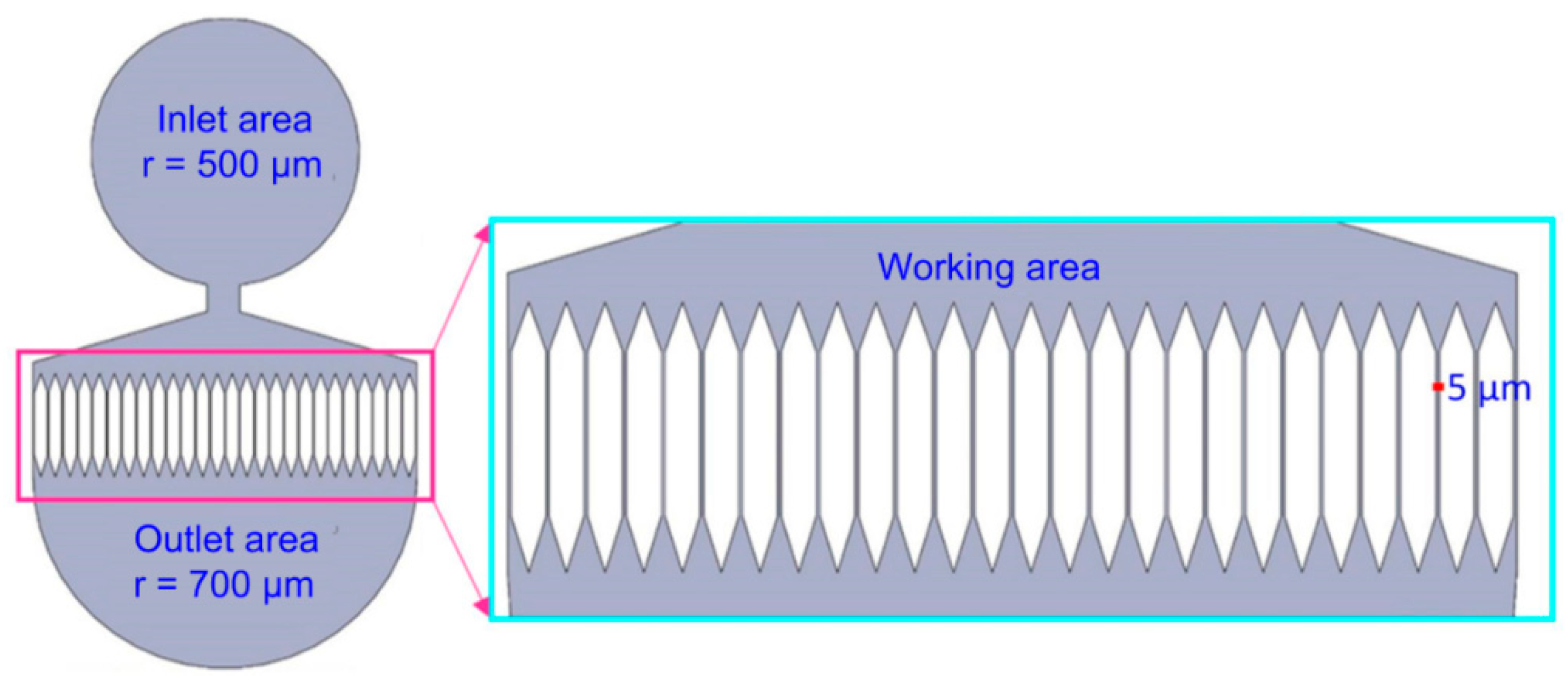
2.1. Design of the Microfluidic Mitochondria Extraction Device

Figure 1 shows a schematic of the proposed microfluidic device for extracting functional mitochondria. We used commercially available SolidWorks software to design the microfluidic device. The device has three parts: an inlet area, working area, and outlet area. The inlet and outlet areas each contained a circular buffer with radius of 500 and 700 μm, respectively. The working area consisted of a microchannel structure to achieve effective cell lysis. We set the smallest channel width as 5 μm because a eukaryotic cell is larger than 10 μm.
The pressure drop in each channel of the device can be described by the following formula:
Δ P = 8 × η × L π × γ 4 Q n
where η (Pa × s) is the coefficient of viscosity; L denotes the length of the microchannel structure; Q (m3/s) is the injected flow rate; n is the number of branches in each layer; and rh (m) is the hydraulic radius of the microchannel. Assuming m channels in a certain layer are clogged by the injected cells and Q is uniform in the other (nm) channels, the pressure drop in each channel can be reformulated as shown in Equation (2). If ΔP’ is large enough to break the cell membrane, the clogged cells will be broken [19].
Δ p = 8 × η × L π × γ h 4 Q ( n m )
The representative shear stress can be estimated using Equation (3).
σ = Δ p × γ h 2 L

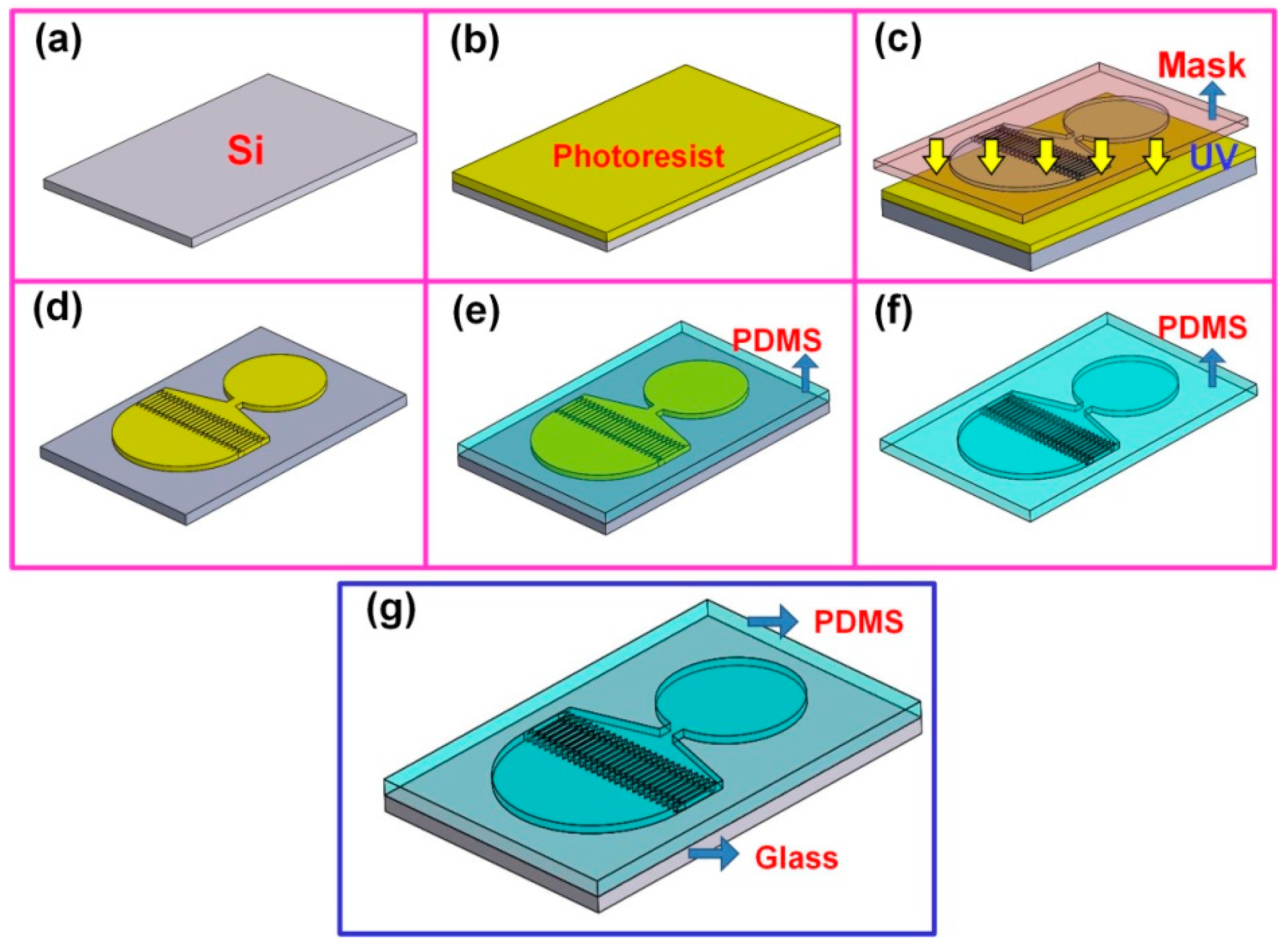
2.2. Fabrication of the Microfluidic Device

The schematic in Figure 2 illustrates the fabrication process of the microfluidic device. We used a 2 cm × 2 cm silicon wafer as substrate, which was washed three times sequentially with deionized water, ethanol, and acetone (Figure 2a). An 8 μm-thick SU8-5 negative photoresist (Microchem, Westborough, MA, USA) was then spin-coated onto the silicon substrate (500 rpm, 10 s; 1500 rpm, 20 s) (Figure 2b). To identify the microfluidic pattern, the substrate was then exposed using a double-sided mask aligner (OAI-500, Optical Associates, Inc., San Jose, CA, USA) (Figure 2c) and developed using an SU-8 developer (Figure 2d). After developing, the PDMS solution (10:1 (v/v) ratio) was cast onto the patterned silicon substrate and dried in an oven overnight at 100 °C (Figure 2e). The PDMS substrate was then separated from the silicon wafer and cleaned with compressed air to remove surface particles (Figure 2f). We then applied atmospheric pressure plasma treatment to the patterned PDMS surface to modify surface property. Finally, the PDMS substrate was bonded to a glass slide under 5-mtorr pressure for 15 min to obtain the microfluidic device (Figure 2g).

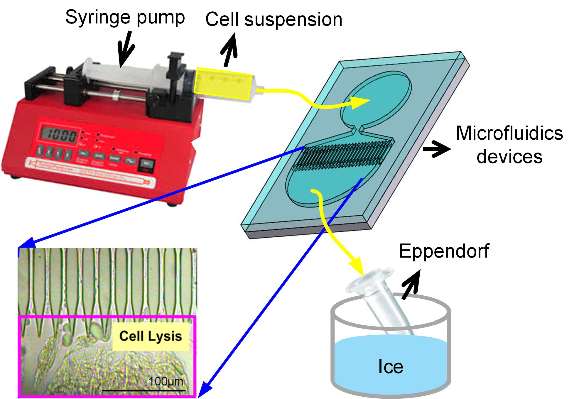
2.3. Cell Culture and Mitochondria Extraction

Human osteosarcoma cybrid cells, carried normal mitochondria derived from the fibroblasts of the healthy individuals, with genetic labeling of green fluorescence protein (GFP) in mitochondria (C2-mitoGFP) were used as a mitochondrial donor for mitochondria extraction. The cells were cultured in an incubator at 37 °C and 5% CO2 with high glucose Dulbecco’s Modified Eagle’s Medium (Gibco, Life technologies Inc., Carlsbad, CA, USA) containing 10% fetal bovine serum (Gibco, Life technologies Inc., USA) and 1% antibiotic-antimycotic buffer (Gibco, Life technologies Inc., USA). The medium was renewed every other day. When cell density reached 80%, cells were passaged by adding trypLE express enzyme (Gibco, Life technologies Inc., USA) for 10 min for further experiments. After centrifugation, the cells were suspended by adding hypo osmotic lysis buffer (RSB hypo buffer, pH 7.5) on ice for 15 min to swell cells.
To obtain the optimal working concentration, the cells were diluted into units of 10, 20, 30, 40, 50, and 100 × 104 cells/mL for mitochondria extraction. The cell solution was then injected into the microfluidic device with a flow rate of 5 mL/h to break cell membranes and the output solution, a mixture of cell homogenate contains organelles, was kept on ice to reserve of mitochondrial activity. Subsequently, a hypertonic solution homogenization buffer (2.5 × MS Homogenization Buffer) was immediately added to reconstruct mitochondria for balance of osmotic pressure. The mitochondria were centrifuged at 13,000× g for 5 min to remove nuclei, unbroken cells, and large membrane fragments. The supernatant was transferred to a clean centrifuge tube and centrifuged at 17,000× g for 15 min to obtain the mitochondrial pellet. Finally, the mitochondria were resuspended with preserved buffer for future experiments.
To compare the activity of mitochondria extracted with the proposed microfluidic system with those extracted by the conventional approach, the cells were treated with either a mitochondria isolation kit (Thermo Fisher Scientific, Waltham, MA, USA) or a freezing and thawing process as the control.

2.4. Protein Assay

A Pierce BCA Protein Assay Kit (Thermo Fisher Scientific) was used to examine the extracted protein. After cell lysis, the solution collected from the microfluidic device was sequentially centrifuged at 3000× g to remove cell debris and then at 10,000× g to discard the cytosol and obtain the mitochondria. We then added a mixing solution of 10 μL of mitochondria solution and 10 μL of standard solution into an enzyme-linked immunosorbent assay (ELISA) plate, followed by 200 μL of BCA working reagent into each well. This mixture was incubated at 37 °C for 30 min, and its absorbance was measured at 550 nm using an ELISA reader. The standard solution was prepared by diluting BSA solution into units of 2000, 1500, 1000, 750, 500, 250, 125, 25, and 0 μg/mL.

2.5. SDS-PAGE and Western Blot

The mitochondrial protein structure was analyzed by using SDS-PAGE and Western blot. A 12% running gel and a 6% sticking gel were prepared separately. We added 12 μg of total protein solution from each sample into SDS-PAGE and then applied 80 V of potential for 135 min to separate the protein. We transferred the protein to a nitrocellulose membrane by applying a current of 200 mA for 60 min. After buffer blocking with 0.1% BSA for 60 min, the primary antibodies (the mouse anti-Tom20 antibody (Santa Cruz Biotechnology, USA) and the rabbit anti-complex I–V antibody (Abcam, Cambridge, MA, USA) were respectively diluted with PBS with 0.1% Tween 20 (PBST) buffer at a 1:1000 (v/v) ratio) were added and incubated overnight at 4 °C. After washing, we incubated the secondary antibodies conjugated with infrared dyes (IRDyes; goat anti-mouse IgG antibody IRDye 800 and goat anti-rabbit IgG antibody IRDye 800 diluted with PBST buffer in 1:10,000 (v/v) ratio, respectively) at room temperature for 90 min in a dark environment. After each step, the membrane was washed with PBST buffer. After rinsing, we measured the membrane with an ODYSSEY infrared imaging system (LI-COR, Lincoln, NE, USA). Image J software was used to quantify the mitochondrial protein.

2.6. Flow Cytometry

To verify the purity and membrane potential of the extracted mitochondria, 10-N-alkyl acridine orange (NAO) and tetramethylrhodamine ethyl ester (TMRE) were used for staining the extracted mitochondria. After staining for 20 min in the dark, a flow cytometer (Cytomics FC 500, Beckman Coulter Inc., Brea, CA, USA) using 530 ± 15 nm band pass filter was employed.

2.7. Examination of Mitochondrial Morphology

To ensure the completeness of the outer membrane of the extracted mitochondria, the morphologies of ultrathin sections were examined by transmission electron microscopy (TEM). Extracted mitochondria after centrifuge at 12,000× g and then pellets were fixed in 2.5% glutaraldehyde in 0.1 M phosphate buffer (pH 7.2) for 4 h at room temperature as around 20 to 25 °C. After three rinses in 0.1 M phosphate buffer for 15 min each, samples were dehydrated through a graded ethanol series for 20 min each. Samples were infiltrated with LR white resin in a gelatin capsule and stored at 4 °C for 48 h. Capsules were polymerized before cutting 70 nm ultrathin sections (Leica EM UC7, Wetzlar, Germany). Sections were viewed using a TEM (Hitachi H-7000, Yokohama, Japan).

3. Results

3.1. Device Structure Selection

In this study, we designed seven types of microfluidic devices as shown in Figure S1. The fabricated silicon base replica molds of the designed microchannel devices with photoresist as the structure are shown in Figure S2. The optical microscopy images of the PDMS based microchannel structures obtained by casting PDMS solutions on the silicon base replica molds are depicted in Figure S3. The optical microscopy images of the cell lysis process using chip-based microfluidic devices are shown in Figure S4. The effectively usable time analysis is presented in Table S1. Based on cell lysis capability, fluidity of the suspension at working area, and effectively usable time, the type 7 device was selected for further mitochondria extraction.

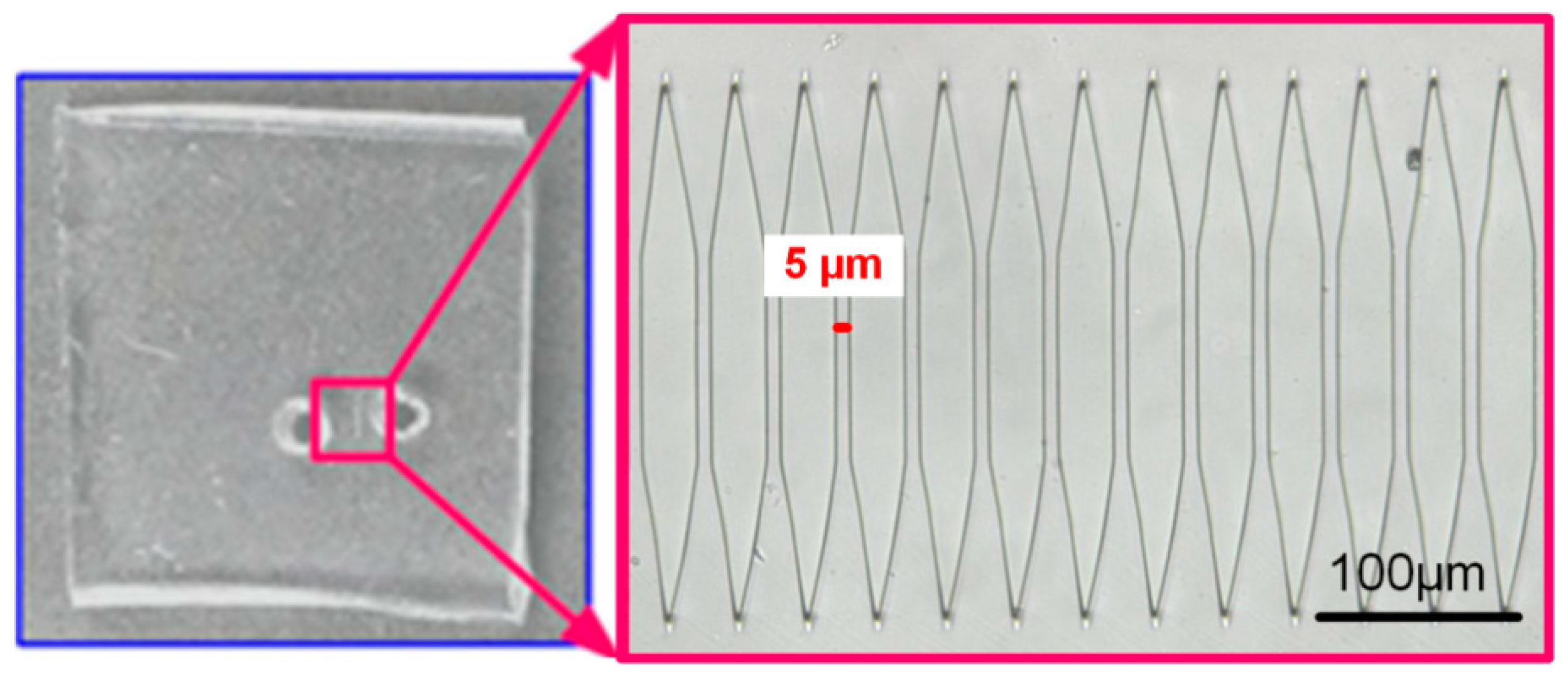
3.2. Chip-Based Microfluidic Device

Figure 3 shows the fabrication result of the type 7 chip-based microfluidic device. The bioMEMS process, including the fabrication of a silicon-based replica mold, PDMS casting and demolding, and packing, was employed to fabricate the microfluidic device. The results indicated that the width of each channel was similar to our designed device. The damage or clogs in the device that resulted from fabrication were not observed. The chip-based microfluidic devices were used for future mitochondria extraction.

3.3. Pressure Drop and Shear Stress

The medium used for cell concentration dilution was PBS. The depth and width of each microchannel are 8 and 5 μm, respectively. The parameters for calculations of pressure drops and shear stresses are listed below.
η = 0.904 mPa-s = 0.922 × 10⁻⁸ kg-s/cm2, L = 60 μm, rh = 4 × 5 × 8/4(5 + 8) μm = 3.077 μm, Q = 5 μL/h = 5 μm3/3600 s = 1.39 × 10⁻³ μm3/s.
The calculated pressure drops (Equation (2)) and shear stresses (Equation (3)) for different m are tableted in Table 1.

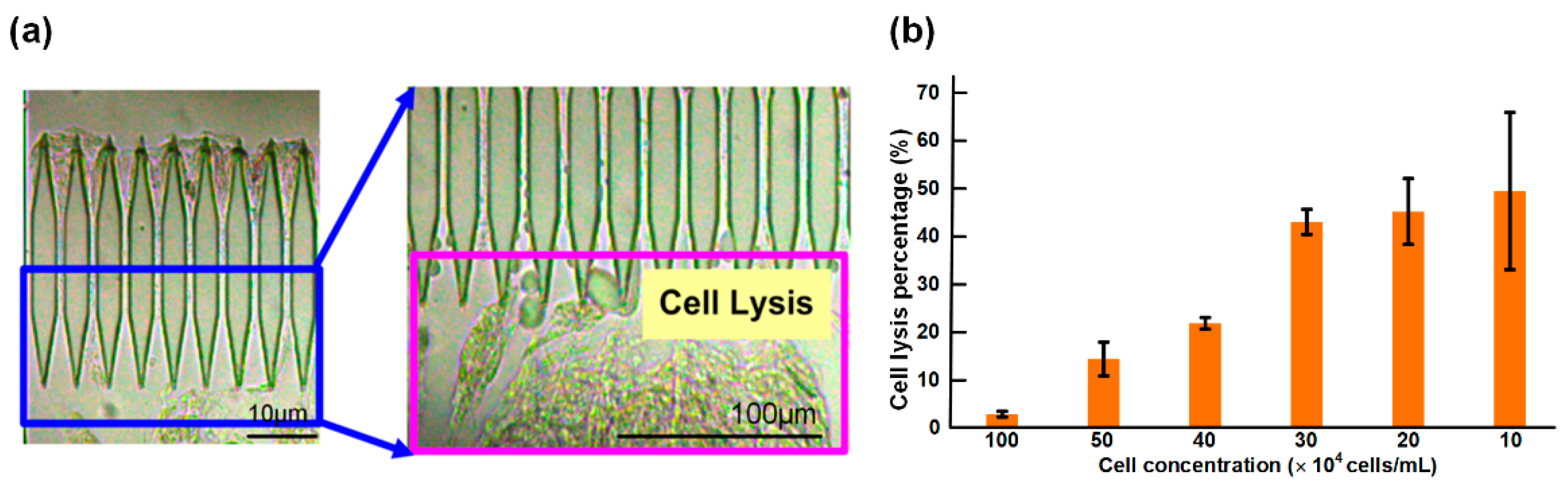
3.4. Working Concentration of the Cell Suspension

The purpose of optimizing the working concentration was to determine an optimal concentration of injected cells that could most efficiently break the cell membrane. In this study, we used a flow rate of 1 mL/min for cell injection. Assuming the injected solution was an incompressible and steady flow in microchannels, the fluid area in microchannels was drastically reduced and led to a remarkable increase in fluid pressure, according to Bernoulli’s principle and the conservation of energy. Therefore, high flow rates of cell injection were used to increase the extraction speed, but high speeds could increase the risk of device damage because of high fluid pressure generated in microchannels.
Figure 4 shows the cell lysis results using the type 7 microfluidic device. The cell lysis results from other devices are not shown (Figure S4). Cells were broken as they passed through the 5 μm microchannels; the cytoplasm, nucleus, and membrane fragments were then released. Based on the high-magnification image in Figure 4a, the released substances (cytoplasm, nucleus, and membrane fragments) easily adhered to the outlet area of the device; this area contained abundant proteins, nucleic acid, and dissolved macromolecules. To prolong the lifetime and increase the extraction efficacy of the device, the optimal concentration of injected cells of the chip-based microfluidic device was measured. Figure 4b shows the efficacy of broken cells using the chip-based microfluidic device under various cell concentrations. The total protein concentration by lysis buffer extraction was 2181.87 μg/mL in a cell suspension solution of 30 × 104 cells/mL. By estimating the ratio of total protein of extracted cells, 50% of injected cells were broken by the microfluidic device at a working concentration of 10 × 104–30 × 104 cells/mL. Moreover, only 3–20% of injected cells were broken at 40 × 104–100 × 104 cells/mL. This finding was attributed to cell aggregate at the high concentration during extracted process to lead to lower crushing efficiency, because the undispersed cells could not pass orderly through microchannels. To effectively obtain complete mitochondria by using the microfluidic device, 30 × 104 cells/mL of cell suspension was selected as the optimal working concentration.

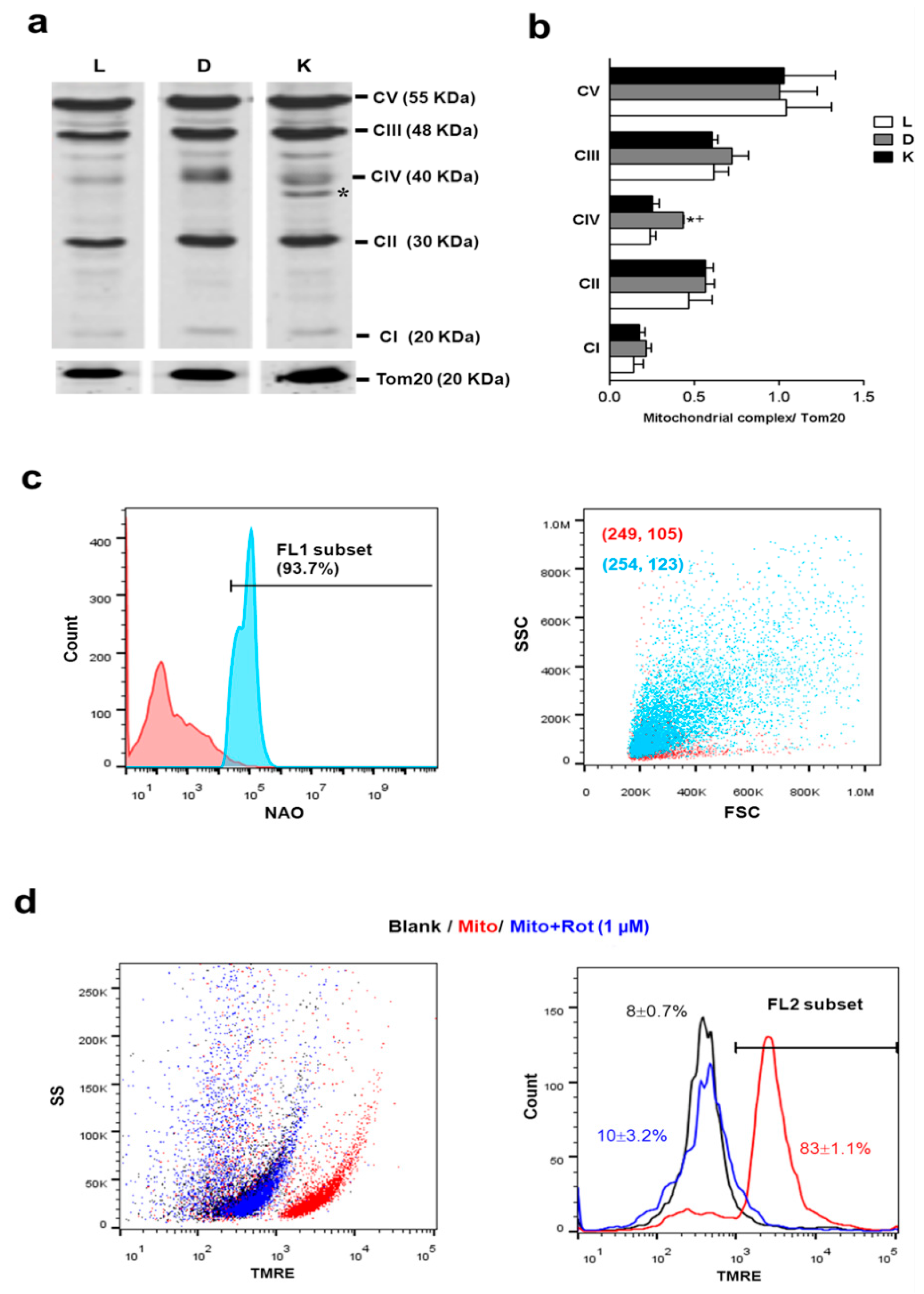
3.5. Function of Device-Extracted Mitochondria

The main purpose of this study was the extraction of functional mitochondria. To measure the activity of the extracted mitochondria, we employed protein electrophoresis for analyzing complex I-V and Tom20 of the extracted mitochondria. Complex I-V consisted of five types of transmembrane proteins on a mitochondrial membrane. These proteins are associated with ATP synthesis in mitochondria and can be used as an index of mitochondrial activity. Tom20, one of the markers of mitochondria, can be used to represent the amount of extracted mitochondria [20,21]. Lysis of whole cell with intact mitochondria inside (L) was used to be a quality control for mitochondrial extraction via proposed devise (D) and conventional kit (K).
Cell protein lysis buffer is normally used for protein extraction so that it presents the performance of intact mitochondrial complexes inside cells.
Figure 5 illustrated the comprehensive measurements of mitochondrial function. Results of Western blot analysis of mitochondrial complex I-V activity in samples derived from different extraction methods are shown in Figure 5a. The similar pattern of mitochondrial complex I-V proteins was found in the groups of device-extraction (D) and cell lysate (L). In contrast, protein of mitochondrial complex IV (CIV) was modified in group of conventional kit because the presence of a band shift was dramatically found bellow the molecular weight of CIV (40 KDa) as a star indicated in Figure 5a. To compare with the other groups, it revealed that chemical reagents of conventional kit possibly change the CIV protein structure. It also meant the activity of kit-extracted mitochondria could be affected by the change of the supercomplex composition of the CIV protein [22]. Thus, the higher preservation of the entire CIV protein was found in a group of device extractions relative to the kit extraction (Figure 5b).
To further verify the purity of the extracted mitochondria, we used NAO dye for specific labeling of the mitochondrial inner membrane. A histogram from flow cytometry analysis illustrated the difference in the non-labeled (red) and NAO-labeled mitochondria (blue; Figure 5c, left panel), which revealed 93.7% of mitochondrial purity in device-extracted substrates. It was similar with conventional kit extraction (97.4% showed in our previous finding [23]). The NAO-positive dot plots indeed confirmed the greater size (indicated by forward scatter signal, FSC) and granularity (indicated by side scatter signal, SSC in extracted mitochondrial population (254, 123) to compare the non-mitochondrial population (249, 105) (Figure 5c), as our previous findings [23].
The mitochondrial membrane potential of extracted mitochondria was examined by TMRE staining (Figure 5d). Mitochondrial complex I inhibitor rotenone (Rot) with valid dose (1 μM) was used to identify the mitochondrial depolarization. The result showed that 83 ± 1.1% of device-extracted mitochondria expressed strong TMRE fluorescence and the population crashed down to 10 ± 3.2% after rotenone treatment, which is similar to the autofluorescence of the blank group (8 ± 0.7%) (Figure 5d, right panel).

3.6. Mitochondrial Ultrastructure of Device-Extracted Mitochondria

TEM images showed the mitochondrial structure of device-extracted mitochondria without density gradient centrifugation. The complete outer membrane and cristae (arrow indicated) were observed at the extracted mitochondria, although some condensed mitochondria indicated as star points were found at same magnifications (Figure 6). The range of mitochondrial size was approximately estimated from 0.5 μm to 1.5 μm. The morphology examination results indicated that our device could break the cell membrane to extract entire mitochondria without mitochondrial membrane disruption.

4. Discussion

Mitochondria are extracted by first damaging the cell membrane to obtain organelles containing cytoplasm and then purified by centrifugation at different speeds. Cell lysis methods can be categorized into solution-based and physical approaches. Solution-based cell lysis involves osmotic shock, freezing and thawing, enzyme lysis, chemical treatment, and detergents [24]. Of these approaches, osmotic shock and freezing, and thawing are most commonly used. In osmotic shock, cells are placed in a solution of high osmolarity, such as glycerine and sucrose, to shrink the cell membrane via the discharge of intracellular water. By diluting the solution, extracellular water quickly flows into the shrunken cells and cells rupture from the rapid expansion of the membranes. In the freezing and thawing approach, cells are first placed in a cryogenic environment and then the frozen cells are dissolved at room temperature. When these steps are performed repeatedly, the cell membranes are broken down. The freezing process also forces intracellular water to form ice grains, which induce cell swelling and rupture. The major weak point of solution-based lysis is that the activity of the extracted mitochondria can be easily damaged because of repeated swelling and/or addition of chemical substances. In addition, this approach is relatively difficult to perform in large quantities. Physical cell lysis approaches include homogenization, shaking beads, fine grinding, and ultrasonication. Of these techniques, homogenization can efficiently obtain large amounts of mitochondria and is the most commonly used. Three types of homogenizers have been developed: the Dounce homogenizer, Potter–Elvehjem homogenizer, and French press [25,26]. High pressure is required to either directly or indirectly destroy cell membranes to acquire mitochondria. However, the applied high pressure is likely to damage mitochondrial activity so that we did not additionally pressurize cells to pass the microchannel for rise the efficiency of cell disruption in the proposed device. In contrast, the designed device in our study provided size-controlled microchannels to gently destroy the suspended cells and obtain functional mitochondria in a continuous fluid at the optimal working concentration of cell suspension. Although the device extracted amount is equal to that extracted by a conventional kit, the quality of device-extracted mitochondria is better than the kit-extracted, which no abnormal assembly of mitochondrial complex proteins.
Considering a rapid and efficient method for extracting intact mitochondria is highly desirable for mitochondria therapy applications, our experimental results also confirmed the feasibility of the proposed microfluidic device for practical applications and the less effect of protein integrity during the process of extraction. Furthermore, in this study, the size of the applied cell was approximately 10–15 μm and it could be progressively broken via the proposed microfluidic device with a microchannel width of 5 μm. Therefore, we proposed that the microfluidic device could be available for other kinds of cells, such as stem cells, within an appropriate cell size of 6–15 μm. Otherwise, different cells may be used simply by adjusting the channel width for desirable application. In addition, a meticulous mask and precise exposure device are also required.

5. Conclusions

In this study, we propose a nontoxic and useful method for mitochondria extraction using a chemical-free microfluidic device. The cast PDMS microfluidic device not only extracted an equal amount of mitochondria to a conventional kit but also preserved mitochondrial function from damage in the extraction process. It is a critical issue for mitochondrial transplantation for therapeutic use in recent years because the efficacy of the mitochondrial treatment is dependent on graft mitochondrial function. The advantage of the proposed device is its ability to maintain isolated mitochondrial quality, including a reduced complexity of operating procedure, the elimination of human error, and the avoidance of chemical contamination in the process of mitochondrial preparation. This pilot study will contribute to developing a technique of massive extraction of cell-based mitochondria by integrating a fluid pressure system in our ongoing approach and facilitate clinical practice in the future.

Supplementary Materials

The following are available online at https://www.mdpi.com/2411-5134/3/4/68/s1.

Author Contributions

Conceptualization, C.-W.L., C.-S.L. and G.J.W.; Data curation, Y.-H.H. and S.-T.C.; Funding acquisition, C.-S.L. and G.-J.W.; Methodology, C.-W.L., J.-C.C. and G.-J.W.; Supervision, C.-S.L. and G.-J.W.; Validation, Y.-H.H., J.-C.C. and S.-T.C.; Writing-original draft, G.-J.W.; Writing-review & editing, J.-C.C.

Funding

This research was funded by the Ministry of Science and Technology of Taiwan under grant number MOST-105-2221-E-005-036-MY3.

Acknowledgments

The authors would like to offer their thanks to the Changhua Christian Hospital, Taiwan for their financial support of this research.

Conflicts of Interest

The authors declare no conflict of interest. The funders had no role in the design of the study; in the collection, analyses, or interpretation of data; in the writing of the manuscript, and in the decision to publish the results.

References

  1. Desler, C.; Rasmussen, L.J. Mitochondria in biology and medicine. Mitochondrion 2012, 12, 472–476. [Google Scholar] [CrossRef] [PubMed]
  2. McBride, H.M.; Neuspiel, M.; Wasiak, S. Mitochondria: More than just a powerhouse. Curr. Biol. 2006, 16, R551–560. [Google Scholar] [CrossRef] [PubMed]
  3. Voet, D.; Voet, J.G.; Pratt, C.W. Fundamentals of Biochemistry, 2nd ed.; John Wiley and Sons, Inc.: New York, NY, USA, 2006. [Google Scholar]
  4. Richter, C.; Park, J.; Ames, B.N. Normal oxidative damage to mitochondrial and nuclear DNA is extensive. Proc. Natl. Acad. Sci. USA 1988, 85, 6465–6467. [Google Scholar] [CrossRef] [PubMed]
  5. Pourahmad, J.; Hosseini, M.J. Toxicity of Arsenic (III) on Isolated Liver Mitochondria: A New Mechanistic Approach. Iran. J. Pharm. Res. 2012, 11, 703–704. [Google Scholar] [PubMed]
  6. Giang, A.H.; Raymond, T.; Brookes, P.; de Mesy Bentley, K.; Schwarz, E.; O’Keefe, R.; Eliseev, R. Mitochondrial Dysfunction and permeability transition in osteosarcoma cells showing the warburg effect. J. Biol. Chem. 2013, 288, 33303–33311. [Google Scholar] [CrossRef] [PubMed]
  7. Knott, A.B.; Perkins, G.; Schwarzenbacher, R.; Bossy-Wetzel, E. Mitochondrial fragmentation in neurodegeneration. Nat. Rev. Neurosci. 2008, 9, 505–518. [Google Scholar] [CrossRef] [PubMed]
  8. Spees, J.L.; Olson, S.D.; Whitney, M.J.; Prockop, D.J. Mitochondrial transfer between cells can rescue aerobic respiration. Cell Biol. 2006, 103, 1283–1288. [Google Scholar] [CrossRef] [PubMed] [Green Version]
  9. Elliott, R.L.; Jiang, X.P.; Head, J.F. Mitochondria organelle transplantation: Introduction of normal epithelial mitochondria into human cancer cells inhibits proliferation and increases drug sensitivity. Breast Cancer Res. Treat. 2012, 136, 347–354. [Google Scholar] [CrossRef] [PubMed]
  10. Masuzawa, A.; Black, K.M.; Pacak, C.A.; Ericsson, M.; Barnett, R.J.; Drumm, C.; Seth, P.; Bloch, D.B.; Levitsky, S.; Cowan, D.B.; et al. Transplantation of autologously derived mitochondria protects the heart from ischemia-reperfusion injury. Am. J. Physiol. Heart Circ. Physiol. 2013, 304, H966–H982. [Google Scholar] [CrossRef] [PubMed]
  11. Kim, P.; Kwon, K.W.; Park, M.C.; Lee, S.H.; Kim, S.M.; Suh, K.Y. Soft Lithography for Microfluidics: A Review. Biochip J. 2008, 2, 1–11. [Google Scholar]
  12. Qin, D.; Xia, Y.; Whitesides, G.M. Soft lithography for micro- and nanoscale patterning. Nat. Protoc. 2010, 5, 491–502. [Google Scholar] [CrossRef] [PubMed] [Green Version]
  13. Kido, H.; Micic, M.; Smith, D.; Zoval, J.; Norton, J.; Madou, M. A novel compact disk-like centrifugal microfluidics system for cell lysis and sample homogenization. Colloids Surf. B Biointerfaces 2007, 58, 44–51. [Google Scholar] [CrossRef] [PubMed]
  14. Lu, K.Y.; Wo, A.M.; Lo, Y.J.; Chen, K.C.; Lin, C.M.; Yang, C.R. Three dimensional electrode array for cell lysis via electroporation. Biosens. Bioelectron. 2006, 22, 568–574. [Google Scholar] [CrossRef] [PubMed]
  15. Jha, S.K.; Ra, G.S.; Joo, G.S.; Kim, Y.S. Electrochemical cell lysis on a miniaturized flow-through device. Curr. Appl. Phys. 2009, 9, e301–e303. [Google Scholar] [CrossRef]
  16. Ikeda, N.; Tanaka, N.; Yanagida, Y.; Hatsuzawa, T. On-chip single-cell lysis for extracting intracellular material. Jpn. J. Appl. Phys. 2007, 46, 6410. [Google Scholar] [CrossRef]
  17. Liu, C. Recent Developments in Polymer MEMS. Adv. Mater. 2007, 19, 3783–3790. [Google Scholar] [CrossRef]
  18. Nisar, A.; Afzulpurkar, N.; Mahaisavariya, B.; Tuantranont, A. MEMS-based, micropumps in drug delivery and biomedical applications. Sens. Actuators B Chem. 2008, 130, 917–942. [Google Scholar] [CrossRef]
  19. Chen, Y.C.; Chen, G.Y.; Lin, Y.C.; Wang, G.J. A lab-on-a-chip capillary network for red blood cell hydrodynamics. Microfluid. Nnaofluid. 2010, 9, 585–591. [Google Scholar] [CrossRef]
  20. Li, Y.; Park, J.S.; Deng, J.H.; Bai, Y. Cytochrome c oxidase subunit IV is essential for assembly and respiratory function of the enzyme complex. J. Bioenerg. Biomembr. 2006, 38, 283–291. [Google Scholar] [CrossRef] [PubMed] [Green Version]
  21. Terada, K.; Kanazawa, M.; Yano, M.; Hanson, B.; Hoogenraad, N.; Mori, M. Participation of the import receptor Tom20 in protein import into mammalian mitochondria: Analyses in vitro and in cultured cells. FEBS Lett. 1997, 403, 309–312. [Google Scholar] [CrossRef]
  22. Ramirez-Aguilar, S.J.; Keuthe, M.; Rocha, M.; Fedyaev, V.V.; Kramp, K.; Gupta, K.J.; Rasmusson, A.G.; Schulze, W.X.; van Dongen, J.T. The composition of plant mitochondrial supercomplexes changes with oxygen availability. J. Biol. Chem. 2011, 286, 43045–43053. [Google Scholar] [CrossRef] [PubMed]
  23. Chang, J.C.; Liu, K.H.; Chuang, C.S.; Su, H.L.; Wei, Y.H.; Kuo, S.J.; Liu, C.S. Treatment of human cells derived from MERRF syndrome by peptide-mediated mitochondrial delivery. Cytotherapy 2013, 15, 1580–1596. [Google Scholar] [CrossRef] [PubMed]
  24. Corcelli, A.; Saponetti, M.S.; Zaccagnino, P.; Lopalco, P.; Mastrodonato, M.; Liquori, G.E.; Lorusso, M. Mitochondria isolated in nearly isotonic KCl buffer: Focus on cardiolipin and organelle morphology. Biochim. Biophys. Acta 2010, 1798, 681–687. [Google Scholar] [CrossRef] [PubMed]
  25. Gross, V.S.; Greenberg, H.K.; Baranov, S.V.; Carlson, G.M.; Stavrovskaya, I.G.; Lazarev, A.V.; Kristal, B.S. Isolation of functional mitochondria from rat kidney and skeletal muscle without manual homogenization. Anal. Biochem. 2011, 418, 213–223. [Google Scholar] [CrossRef] [PubMed] [Green Version]
  26. Hornig-Do, H.T.; Günther, G.; Bust, M.; Lehnartz, P.; Bosio, A.; Wiesnera, R.J. Isolation of functional pure mitochondria by superparamagnetic microbeads. Anal. Biochem. 2009, 389, 1–5. [Google Scholar] [CrossRef] [PubMed]
Figure 1. Schematic of the proposed microfluidic device for extracting mitochondria.
Inventions 03 00068 g001
Figure 2. Schematic of the fabrication process of the microfluidic device: (a) wafer cleaning, (b) photoresist coating, (c) exposure, (d) development, (e) casting, (f) demolding, and (g) packaging.
Inventions 03 00068 g002
Figure 3. Chip-based microfluidic device.
Inventions 03 00068 g003
Figure 4. (a) Cell lysis by the chip-based microfluidic device; (b) cell lysis percentage by using the chip-based microfluidic device under different cell concentrations (n = 3).
Inventions 03 00068 g004
Figure 5. Comprehensive measurement of isolated mitochondrial function via different extracted methods. (a) The performance of mitochondrial complex I-V proteins (CI-CV) was analyzed and (b) quantified by normalizing the mitochondrial amount presented by the mitochondrial marker protein of Tom20. * p < 0.05, significant difference to compare with L group. + p < 0.05, significant difference to compare with K group.(c) Purity of device-extracted mitochondria was analyzed by flow cytometry using 10-N-nonyl acridine orange (NAO) dye for specifically label mitochondria in the inner membrane. Population NAO-positive signals (bluish histogram) was gating by adjusting the autofluorescence of mitochondria without staining (blank group, reddish histogram, left panel). (c) The dot plot of the forward scatter/side scatter (FSC/SSC) showed the difference in particle size and granularity between mitochondrial (bluish dot plot) and non-mitochondrial populations (red dot plot) (right panel). (d) Tetramethylrhodamine ethyl ester (TMRE), mitochondrial membrane-dependent dye, was conducted to measure activity of device-extracted mitochondria with mitochondrial inhibitor rotenone (Rot) (Mito+Rot group, blue dot plot and histogram) treatment for 30 min by flow cytometry or not (Mito group, red dot plot and histogram) (left panel). The population of active mitochondria in each group was quantified by gating autofluorescence of mitochondria without staining (blank group, dark dot plot and histogram) (right panel). L: total cell lysis, D: microfluidic device, K: commercially available mitochondria isolation kit.
Inventions 03 00068 g005
Figure 6. Ultrastructure of device-extracted mitochondria was detected by transmission electron microscopy (TEM). Scale bar is 0.5 μm in each image. The arrow and star indicate the mitochondrial cristae and condensed ultrastructural transformation, respectively.
Inventions 03 00068 g006
Table 1. Calculated pressure drops (ΔP) and shear stresses (σ) for different m.
nmΔP (mPa)σ (mPa)
3006.73 × 10−51.722 × 10⁻⁶
3058.40 × 10−52.15 × 10⁻⁶
301010.49 × 10−52.69 × 10⁻⁶
301513.99 × 10−53.58 × 10⁻⁶

