1. Introduction
The High-Luminosity LHC (HL-LHC) will broaden the prospects of the current LHC in terms of new physics discoveries. The desired instantaneous luminosity of the HL-LHC is
10
cm
s
, seven times the LHC’s original parameter (
10
cm
s
). The availability of this increased datasets will help in the high precision measurements of the Standard Model (SM), and in the search of new territories beyond the SM (BSM).
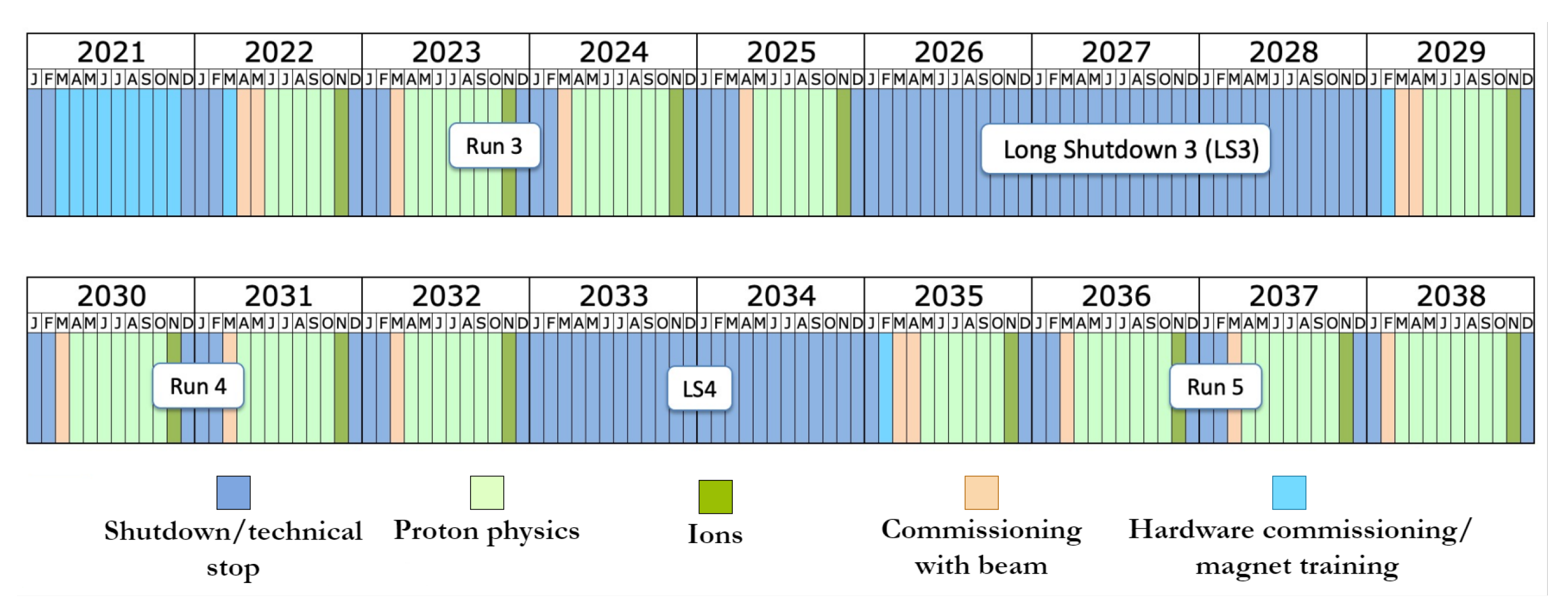
Figure 1 shows the LHC’s schedule and the timeline for the HL-LHC.
Figure 1.
The LHC timeline, and its evolution to the HL-LHC (May 2029 to October 2038) after Long Shutdown 3.
Figure 1.
The LHC timeline, and its evolution to the HL-LHC (May 2029 to October 2038) after Long Shutdown 3.
The CMS detector will encounter a massive upgrade to avail the benefits and sustain the high radiation of the HL-LHC phase. This includes the replacement of the pixel and strip tracking detector, replacing the end-cap calorimeter with a more radiation tolerant high-granularity calorimeter (HGCAL), and completely new back-end and front-end electronics for the barrel calorimeter to attain finer granularity.
The Phase-2 upgrade of the CMS trigger system will maintain the two-level triggering strategy during the HL-LHC. The Level-1 trigger comprises custom design electronics, and at the second stage, a CPU farm-based High-Level Trigger (HLT) is employed [
1]. During HL-LHC, the desired latency of the L1-trigger will increase from 4
s to 12.5
s. This increased latency permits the inclusion of the tracker data and high granular information from the HGCAL. The prominent features of the Phase-2 Level-1 trigger are [
2]:
The large-scale use of Xilinx Stacked Silicon Interconnect (SSI) technology-based FPGA. SSI-based FPGAs are fabricated by stacking several FPGA dies or super logic regions (SLRs). These large FPGAs can handle the significant challenges of the L1 trigger in terms of high speed serial communications, efficient reconstruction, latency, and resource constraints.
The employment of the high-speed optical link (28 Gb/s) to meet the high bandwidth requirement of the HL-LHC. These high-speed links will assist in rapidly relaying the data from the detector back-end system to the L1 trigger chain.
A flexible, modular, and scalable implementation of the calorimeter trigger algorithm. This approach is advantageous to address the HL-LHC dynamic running condition, changes in the hardware choices, and physics needs.
In this paper, we will discuss the Level-1 calorimeter trigger system and its hardware aspects, firmware implementation, latency, scalability, and the bitstream test on the prototype board.
2. Level-1 Calorimeter Trigger
The Level-1 calorimeter trigger processes the four calorimeter sub-detector system. The barrel part comprises the electromagnetic calorimeter (ECAL) and the hadronic calorimeter (HCAL), and the forward area includes the HGCAL and the forward hadronic calorimeter (HF). The key calorimeter trigger objects are: jets, photons, electrons, energy sums, and hadronically decaying taus.
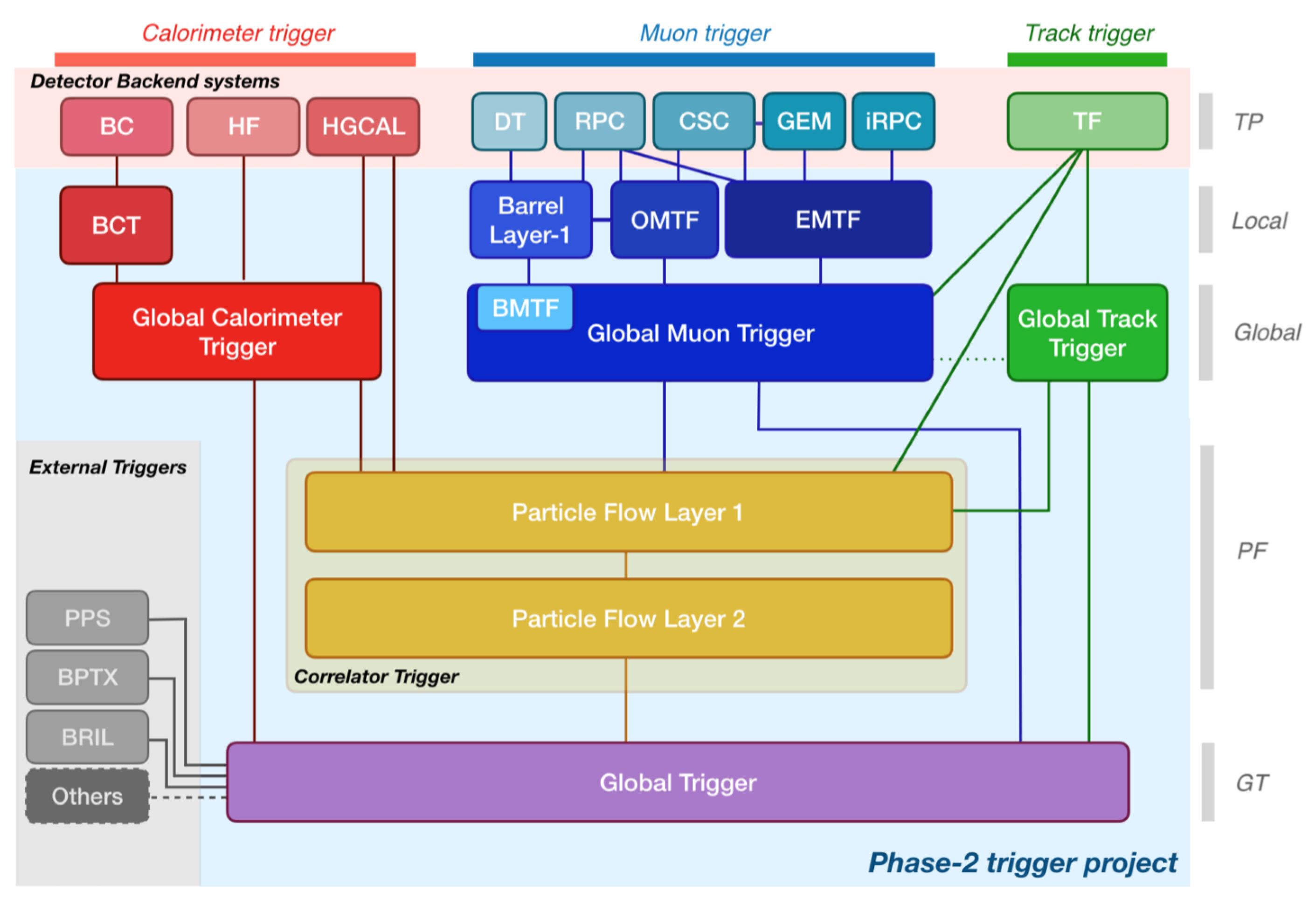
Figure 2 illustrates the block diagram of Phase-2 Level-1 trigger.
Figure 2.
Block diagram of Phase-2 Level-1 trigger system [
2]. It processes the information from sub-detectors, such as calorimeter, muon, and tracker. The trigger system is divided into five layers: backend (generate the trigger input known as trigger primitives), local, global, particle-flow (PF), and global trigger (GT). The calorimeter trigger is implemented in two steps: barrel calorimeter trigger (BCT) and global calorimeter trigger (GCT). The muon trigger system takes input from muon spectrometers: the drift tube (DT), resistive plate chamber (RPC), cathode ray strip (CSC), and gas electron multiplier (GEM). The muon trigger reconstructs the muon tracks using the barrel muon track finder (BMTF), overlap muon track finder (OMTF), and endcap muon track finder (EMTF). It combines the muon’s information in a global muon trigger (GMT). The track trigger comprised the backend track finder (TF) and global track trigger (GTT). The correlator trigger (CT) is implemented in two layers, viz. particle-flow layer-1 and particle-flow layer-2. The GT is planned to possibly explore triggering by taking information from external components such as precision proton spectrometer (PPS) [
3], beam position and timing monitors (BPTX), and luminosity and beam monitoring detectors (BRIL) [
4].
![Instruments 06 00064 g002]()
The detector back-end system collects the raw collision data from the front-end electronics and delivers the trigger primitive (input) to the downstream processing board. The central barrel calorimeter (ECAL and HCAL) is processed in two steps. The barrel calorimeter trigger (BCT), also known as the regional calorimeter trigger (RCT), creates the electron/photon clusters (accumulation of ECAL crystal energies) and towers (a group of 25 ECAL crystals) and sends them to the global calorimeter trigger (GCT).
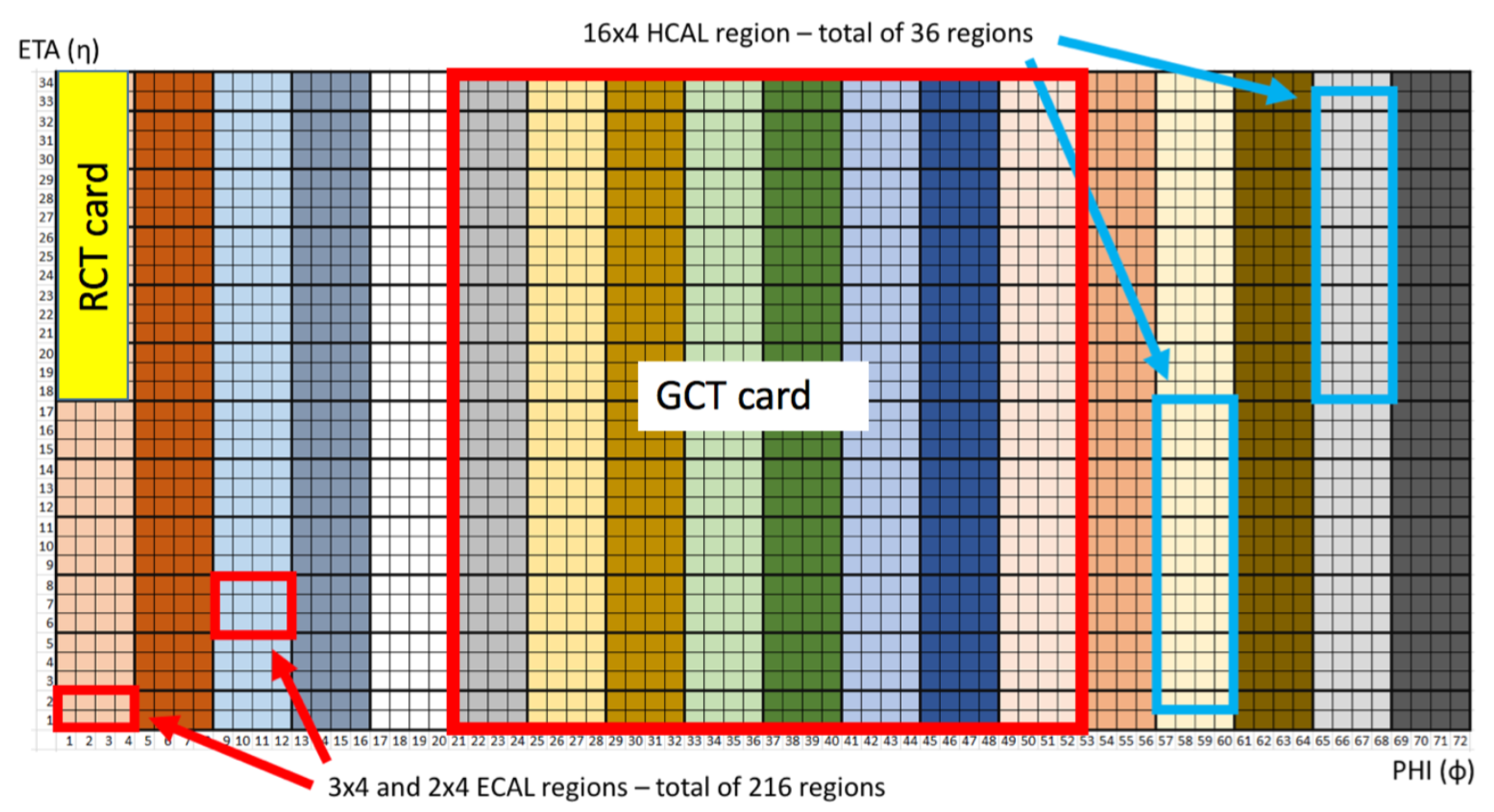
Figure 3 demonstrates the geometry of the barrel and the coverage of the RCT and the GCT FPGA cards.
A single RCT card covers a region of 17
towers. A total of 36 RCT cards are required to process the complete barrel information. A single GCT card evaluates 16 RCT cards, of which 12 are unique while the other 4 are the neighboring RCT card to share the boundary condition. It requires three GCT cards to cover the complete barrel. The calorimeter trigger uses a time-multiplex scheme to transmit data between the trigger sub-systems [
5]. It increases the system’s flexibility and removes the constraint of boundary sharing between the FPGAs. The two primary tasks of the GCT algorithm are:
Prepare and transmit the RCT and HF information in a time-multiplex manner to the correlator trigger (CT).
Demultiplex the incoming HGCAL time-multiplexed data, merge it with the calorimeter-wide signals from ECAL, HCAL, and HF, and send it to the global trigger (GT).
Figure 3.
CMS barrel calorimeter segmentation. The
x-
represents the integer azimuthal angle (each integer represents 5 degrees in
). The
y-
represents the integer
or pseudorapidity (derived from the polar angle of the LHC coordinate system) [
6]. This region represents the ECAL (34
) and HCAL (32
) barrel geometry. Each small square represents one tower of HCAL and ECAL. For ECAL, one tower represents 25 ECAL crystal. The geometry of 17
is the processing region for one RCT card.
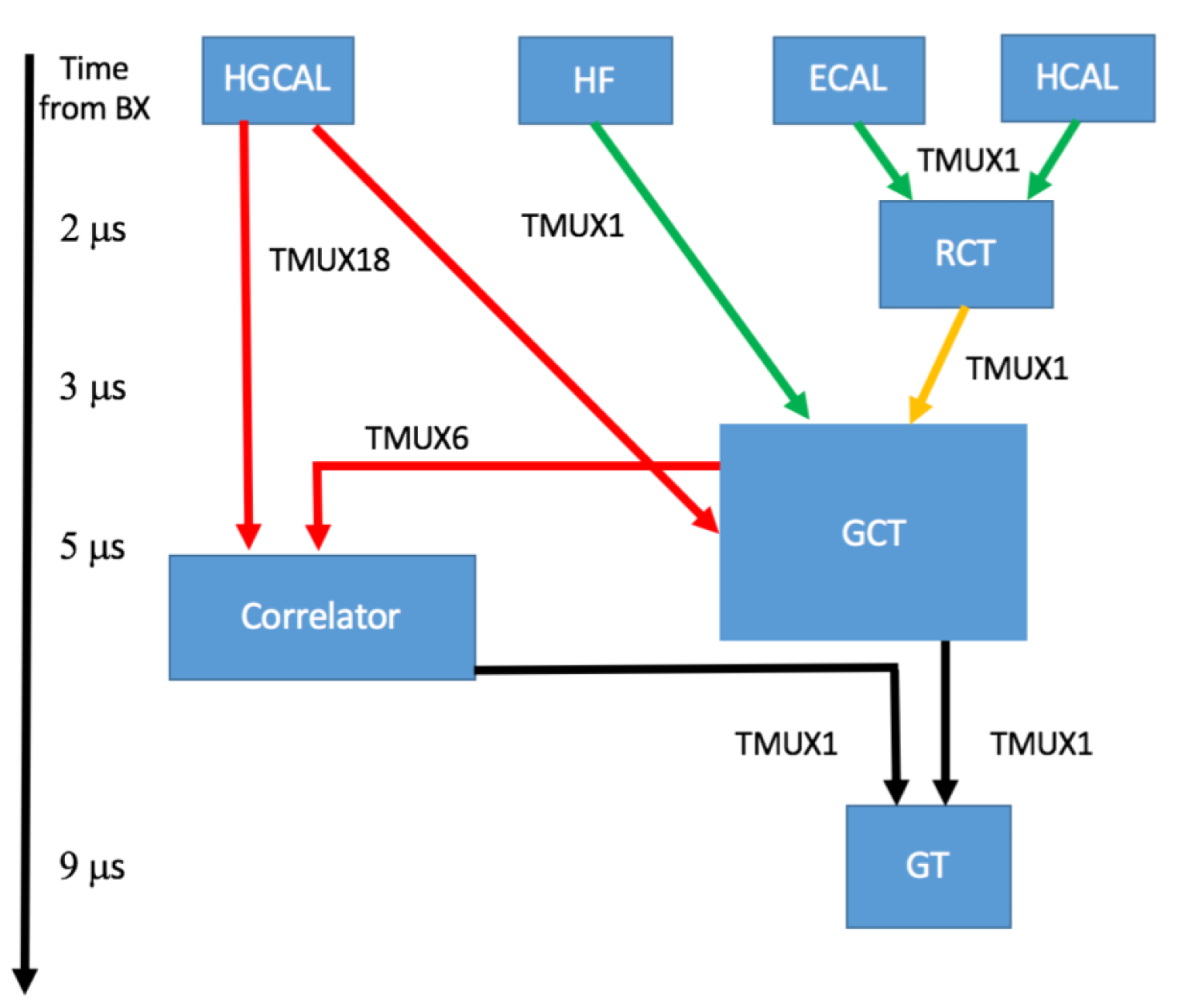
The desired latency budget to provide input to the CT via GCT is 5
s, and the GCT must send the output to the GT within 9
s from the bunch-crossing.
Figure 4 represents the L1 calorimeter trigger architecture and its time-multiplexing and latency scheme.
3. Trigger Algorithms and Hardware Implementation
The calorimeter trigger algorithms are implemented in the Xilinx XCVU9P FPGA, and their latency and resource utilization are presented. In the Phase-2 upgrade, the RCT algorithm receives the input data from each ECAL crystal, increasing the granularity 25 times compared to the Phase-1 trigger system. Similarly, the GCT algorithm for the HGCAL (endcap calorimeter) has the advantage of using high-granular input information from the HGCAL back-end system. The following section describes the calorimeter trigger development and floor-planning, RCT algorithm, and the GCT algorithm.
3.1. Calorimeter Trigger Development and Floorplanning
The calorimeter trigger algorithms are developed with the help of the high-level synthesis (HLS) tools such as Vivado-HLS [
7]. This tool synthesizes the algorithms written in a higher-level sequential language such as C++ and generates the hardware description language (HDL). Vivado-HLS also provides the early estimation of the latency and utilization. One of the main advantages of Vivado-HLS is the rapid prototyping of the trigger algorithms, and ease of performing firmware evaluation with the emulator (C++) generated output. The HDL wrapper integrates the HLS-generated IP with the firmware shell in the downstream implementation. The multi-gigabit transceivers (MGTs) used for the trigger algorithms inputs and outputs are spread across the FPGA boundary. Without crossing the SLR boundary, each SLR possesses a fraction of these MGTs. For example, the SLR1 of XCVU9P FPGA can access only 40 (out of 96 available) MGTs. The division of the HLS algorithms in SLRs reflects the constraint of these distributed MGTs.
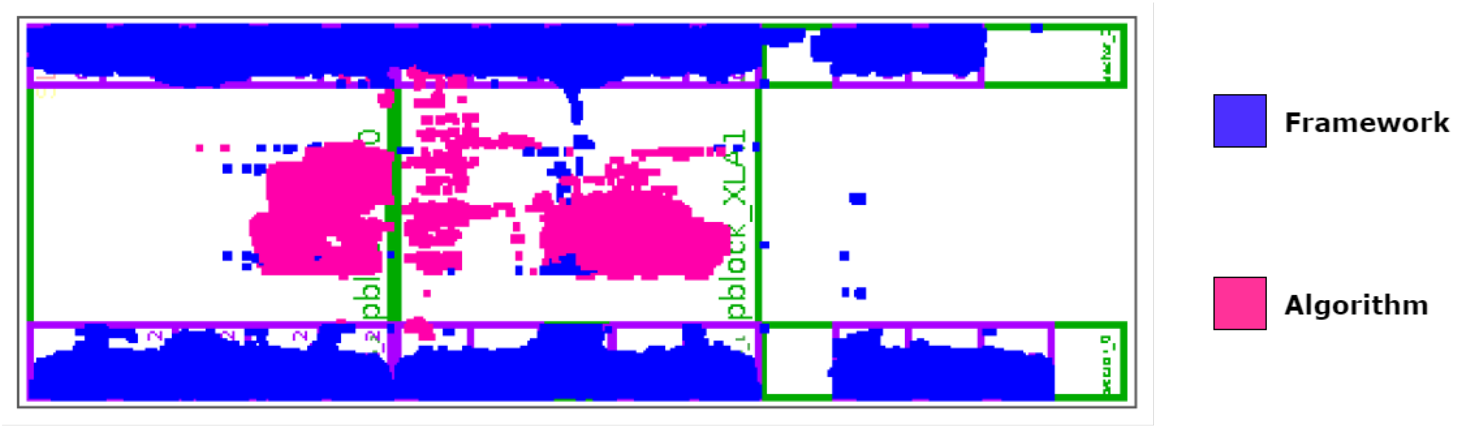
Figure 5 reflects the floorplan of the calorimeter trigger algorithm.
3.2. Regional Calorimeter Trigger (RCT)
The RCT algorithm processes the entire geometry of the barrel ECAL and HCAL. It creates the electron/photon clusters and towers and forwards them to the global calorimeter trigger (GCT). The RCT algorithm processes the region of 17
of ECAL and 16
of HCAL. The critical step of this algorithm is to find the seed crystal, build a cluster of size 3
(crystal level) around the seed, build the bremsstrahlung area (two 3
regions around the central cluster in both left and right of
), and build the shape area (two 2
areas, to differentiate between electrons and hadrons). The RCT algorithm employs a stitching logic that merges the lower cluster energy into the higher one and nullifies the energy of the lower cluster based on their position in
and
.
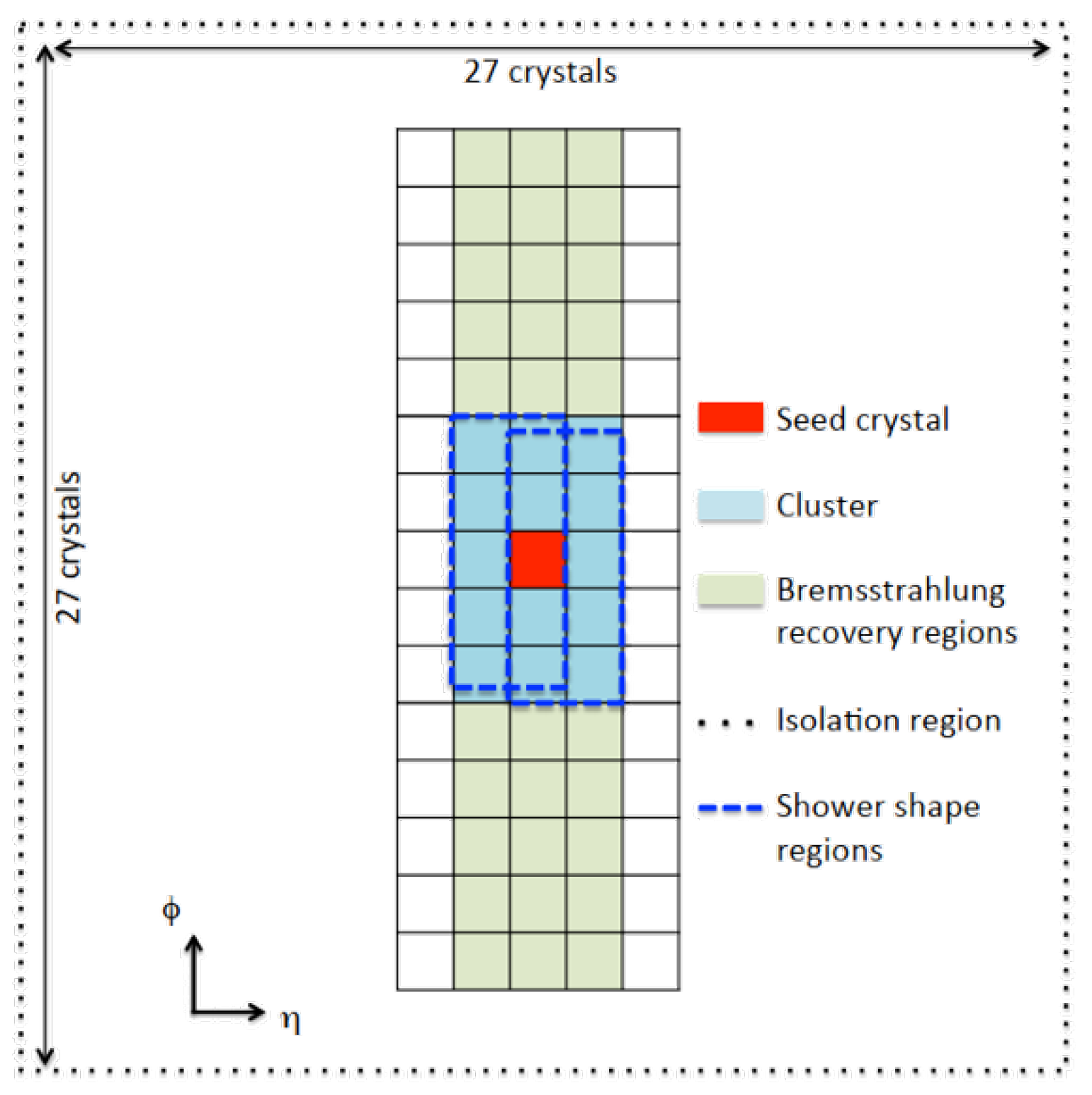
Figure 6 illustrates the RCT coverage and clusters geometry which is described in [
2].
The input and output fiber bandwidth is 16 Gbps which carries 384 bits/bunch-crossing (bits/BX) of data. The RCT region is divided into two SLRs (SLR1 and SLR2) to ease the MGTs requirement while saving the SLR0 for future use. The algorithm processes the region of 8 (RCT) in SLR1 and 9 (RCT) in SLR2. The RCT and RCT process 68 input ECAL links (each link carries 25 crystals information), and RCT considers two additional HCAL links. RCT output in SLR1 is routed to the SLR2 using the super long line (SLL) of the XCVU9P FPGA. In contrast, the RCT output is buffered to match the additional routing delay of the RCT output. This buffering ensures that the RCTSUM algorithm in SLR2 receives both outputs simultaneously. The RCTSUM algorithm stitches the RCT and RCT algorithm at its boundary and computes the h/e (HCAL to ECAL energy ratio) over the entire RCT geometry, and prepares the four output links to the GCT.
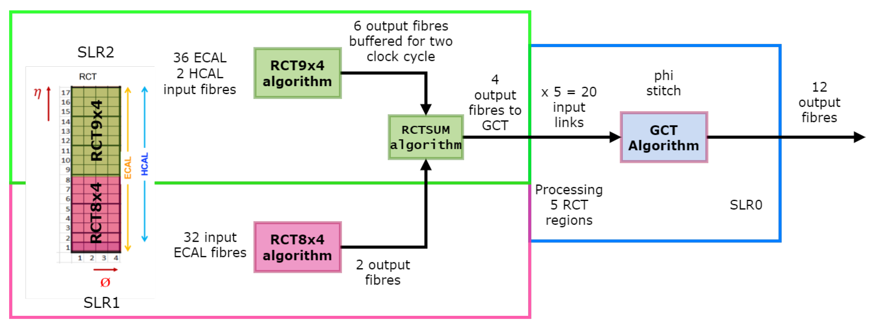
3.3. Global Calorimeter Trigger (GCT)
GCT is a collection of several calorimeter trigger algorithms to process various physics objects. It includes the jet, taus, missing transverse energy (MET),
, and
stitch algorithm. The
stitch (GCT) and RCT algorithms are implemented in SLR0, SLR1, and SLR2, respectively. This implementation demonstrates the working of RCT and GCT together in a single FPGA card. Therefore, the RCT output is replicated five times at the SLR0 to mimic the testing of a GCT algorithm processing five RCT cards simultaneously. The four output links from RCTSUM are buffered while routing it from SLR2 to SLR0. This buffering helps meet the timing constraint of the 240 MHz algorithm clock and prevents any setup time violation in SLR0.
Figure 7 demonstrates the single card test implementation of the RCT and GCT algorithm.
4. Results and Tests
The RCT and GCT algorithms are implemented in Vivado-HLS with a clock frequency of 240 MHz and a pipeline interval of 6 clock cycles. The bitstream for the XCVU9P C2104 package FPGA is generated by integrating the HLS IP with the firmware shell using the HDL wrapper. The latency of the RCT and GCT algorithms is 230 and 120 clock-cycles (combined latency of 1.458
s), respectively. The device utilization of the integrated RCT and GCT algorithms along with the firmware shell is listed in
Table 1.
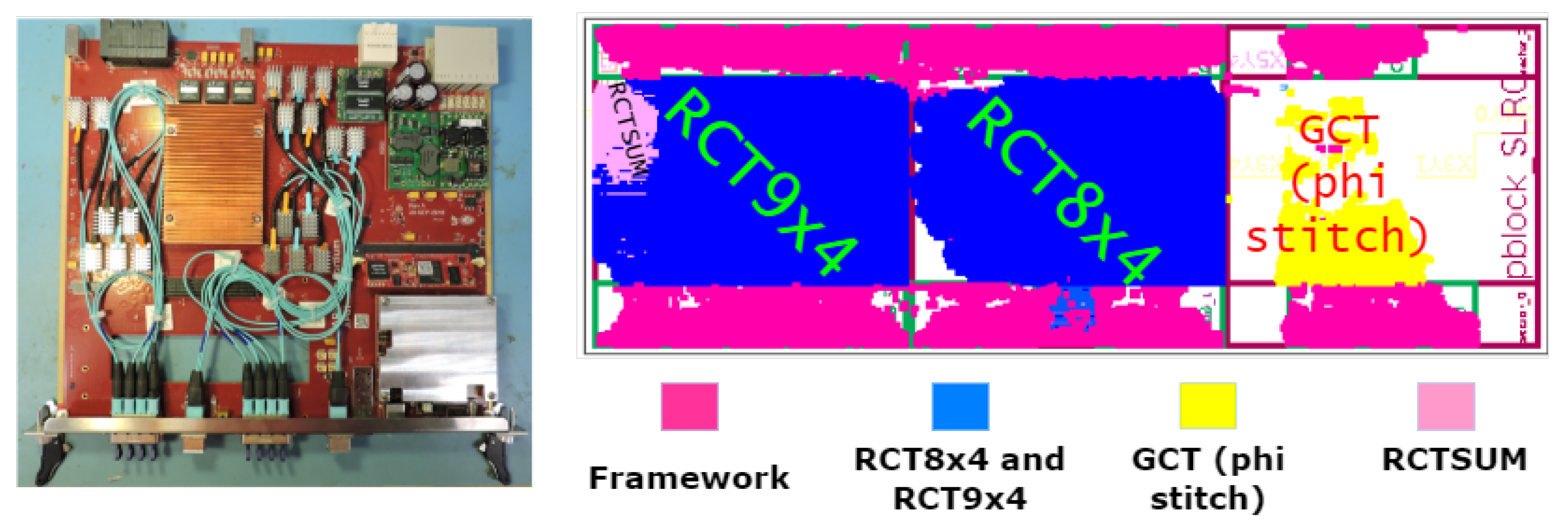
The RCT algorithm is implemented in XCVU9P FPGA utilizing only two SLRs (SLR2 and SLR1) while leaving the SLR0 for the GCT phi stitch algorithm. The bitstream is generated and successfully tested on the first advanced processor demonstrator (APd1) board, which hosts the XCVU9P FPGA.
Figure 8 shows the APd1 board and the placement of the integrated RCT and GCT algorithm on XCVU9P FPGA.
5. Conclusions
The HL-LHC calorimeter trigger algorithm for the barrel calorimeter (RCT and GCT) is developed using the Vivado-HLS tool. The algorithms are implemented and tested on the APd1 board. The combined latency is 1.458 s (RCT and GCT phi stitch), which is within the desired budget of 2 s. The resource utilization is 42% of the LUT, 26% of the flip-flop, and 24% of the BRAM. Several algorithms at the GCT, such as jet, taus, and missing transverse momentum (MET), are being developed.
Author Contributions
Conceptualization and Methodology—B.G., and P.K.; Validation: B.G., and P.K.; Software: B.G.; Formal Analysis: B.G., and P.K.; Data Curation—P.K.; Project Administration—B.G.; Funding Acquisition—B.G. All authors have read and agreed to the published version of the manuscript.
Funding
This research was funded by IOE, University of Hyderabad, grant number UOH-IOE-RC2-21-006.
Institutional Review Board Statement
Not applicable.
Informed Consent Statement
Not applicable.
Data Availability Statement
Not applicable.
Conflicts of Interest
The authors declare no conflict of interest.
References
- Khachatryan, V.; Sirunyan, A.M.; Tumasyan, A.; Adam, W.; Asilar, E.; Bergauer, T.; Brandstetter, J.; Brondolin, E.; Dragicevic, M.; Erö, J.; et al. The CMS trigger system. J. Instrum. 2017, 12, P01020. [Google Scholar] [CrossRef]
- The Phase-2 Upgrade of the CMS Level-1 Trigger; Technical Report CERN-LHCC-2020-004. CMS-TDR-021; CERN: Geneva, Switzerland, April 2020; Available online: http://cds.cern.ch/record/2714892 (accessed on 30 July 2022).
- The CMS Collaboration. The CMS Precision Proton Spectrometer at the HL-LHC Expression of Interest; Technical Report; CERN: Geneva, Switzerland, November 2020; Available online: https://cds.cern.ch/record/2750358 (accessed on 30 July 2022).
- Karacheban, O. Performance of the BRIL luminometers at CMS in Run 2. In Proceedings of the European Physical Society Conference on High Energy Physics (EPS-HEP) 2019, Ghent, Belgium, 10–17 July 2019; Volume 194. [Google Scholar] [CrossRef]
- RicFrazier, R.; Fayer, S.; Hall, G.; Hunt, C.; Iles, G.; Newbold, D.; Rose, A. A demonstration of a time multiplexed trigger for the cms experiment. J. Instrum. 2012, 7, C01060. [Google Scholar] [CrossRef] [Green Version]
- Wong, C.Y. Introduction to High-Energy Heavy-Ion Collisions; World Scientific: Singapore, 1994. [Google Scholar]
- O’Loughlin, D.; Coffey, A.; Callaly, F.; Lyons, D.; Morgan, F. Xilinx vivado high level synthesis: Case studies. In Proceedings of the 25th IET Irish Signals Systems Conference 2014 and 2014 China-Ireland International Conference on Information and Communications Technologies (ISSC 2014/CIICT 2014), Limerick, Ireland, 26–27 June 2014; pp. 352–356. [Google Scholar] [CrossRef]
| Publisher’s Note: MDPI stays neutral with regard to jurisdictional claims in published maps and institutional affiliations. |
© 2022 by the authors. Licensee MDPI, Basel, Switzerland. This article is an open access article distributed under the terms and conditions of the Creative Commons Attribution (CC BY) license (https://creativecommons.org/licenses/by/4.0/).


