Article

Upgrade of the HIVIPP Deposition Apparatus for Nuclear Physics Thin Targets Manufacturing

1
Legnaro National Laboratories, Italian National Institute of Nuclear Physics (LNL-INFN), Viale dell’Università, 2, 35020 Legnaro, PD, Italy
2
Department of Industrial Engineering, University of Padova, Via F. Marzolo, 9, 35131 Padova, PD, Italy
3
SCK-CEN, 2400 Mol, Belgium
*
Authors to whom correspondence should be addressed.
Instruments 2022, 6(3), 23; https://doi.org/10.3390/instruments6030023
Submission received: 5 July 2022 / Revised: 25 July 2022 / Accepted: 29 July 2022 / Published: 1 August 2022
(This article belongs to the Special Issue Feature Papers in Instruments 2021–2022)

Abstract

:
The High Energy Vibrational Powder Plating (HIVIPP) technique allows for the preparation of targets starting from refractory metal powders with negligible material losses during the process, thus preserving the expensive isotope-enriched materials. An upgraded HIVIPP apparatus was developed at the Legnaro National Laboratory of the National Institute of Nuclear Physics (INFN-LNL), and it is reported in this work. Particular attention was paid to the design of the sample holder, the automation of the power supply, and the control of the process, all with the aim of obtaining a versatile and reliable apparatus. Several tests have been carried out and the related results are reported proving the flexibility of the apparatus and the process reproducibility. The main result is a ‘ready to use’ technology at INFN-LNL for the preparation of isotopically enriched refractory metal targets that cannot be manufactured using standard techniques.

1. Introduction

Nuclear physics studies often require isotopically enriched material targets having an area mass density in the range l µg/cm2–10–20 mg/cm2. The targets should be manufactured appropriately to have a uniform thickness distribution, good mechanical strength, high chemical purity and keep integrity during the beam irradiation time.
The most standard nuclear target manufacturing techniques (e.g., vacuum evaporation with e-beam and resistive source, FIB-sputtering, powder pressing, rolling, electrodeposition, different types of sedimentation, etc.) are efficiently used for a considerable number of materials with some exceptions, such as the refractory metals (e.g., Ti, Mo, W, Zr, Hf) [1]. Indeed, due to their high melting temperatures, they are difficult to evaporate even under vacuum conditions. Materials such as Mo, Nb and Ti, with a high affinity for oxygen, cannot be deposited in the form of pure metallic films by electrodeposition from aqueous solutions. Foil rolling, from oxygen-sensitive refractories, provides good quality targets only when a bulk ingot of material is used in an inert gas atmosphere. However, isotopically enriched materials, typically used for nuclear studies, are usually supplied in powder form, and rolling, followed by preliminary powder pressing, results in very poor quality targets while working with refractory metals. In addition, when isotope-enriched materials are used for target preparation, a technique that provides minimal material losses is absolutely required to keep the final cost as low as possible.
In 1997, Isao Sugai [2] proposed the High Energy Vibrational Powder Plating (HIVIPP) method that provides a solution to the two above-mentioned problems: minimal losses and the deposition of “problematic” refractory metals. In the next decade, several modifications of this technique were proposed by the same group, increasing the set of materials deposited [3,4,5,6,7].
The HIVIPP technique allows for the manufacturing of targets for nuclear physics studies with an area mass density ranging from about l µg/cm2 up to mg/cm2 with a very high yield and excellent thickness homogeneity. This method is based on the motion of the powder inside an electric field. Two target substrates are placed in contact with two electrodes, at the top and bottom, separated by a quartz cylinder in which the powder to be deposited is inserted. This system is placed in a vacuum chamber, and a high electric voltage is applied to the electrodes. As a result of the generated electric field, the powder starts to be electrically charged and quickly moves towards the electrode having opposite charge (typically when the voltage reaches 3 kV). When the powder particles achieve enough kinetic energy, they start to be deposited onto the substrate surface (usually it is required >10 kV voltage). During the HIVIPP process, two targets are produced simultaneously, which is particularly interesting for targets using isotope-enriched materials, due to the negligible losses of these expensive powders and the low amount (usually ~20 mg) necessary for each deposition.
Besides the high-pressure apparatus version proposed by the same group [5], no other significant modifications of the system have been reported in the literature. In a previous author’s work [8], the HIVIPP technique was used to prepare 48Ti targets for nuclear cross section measurements, using a set-up similar to the one suggested by I. Sugai [2]. However, some limitations of such a set-up were observed. First, the assembly and disassembly operations of the sample holder were not so handy and required two people, one to keep the substrates and the cylinder fixed and the other one to secure the system with screws. In addition, the thickness of the substrates was limited to a maximum of 100 µm, otherwise the parallelism between the top and bottom parts was not guaranteed. This is due to the non-uniform spring press on the top electrode. These aspects could cause the powder to escape, sometimes with a consistent loss of the costly isotope-enriched material. Furthermore, the centering of the substrates and cylinder was not guaranteed; this aspect is important when the cyclotron target station, where the target will be used, has a fixed dimension and the irradiation beam has a specific spot size. For noticeable reasons, the difficulty during the assembly and disassembly steps of the system made impossible the use of a glove-bag or a glove-box in the case when oxygen-sensitive materials are processed. Furthermore, such a sample holder did not ensure the pumping out of the residual oxygen from the volume inside the cylinder where the deposition takes place. In some cases, electric discharge effects during the high voltage phase were visually observed. In those cases, the process stopped working, so the voltage level should be manually decreased and then increased to restart again the deposition. Usually, the depositions take more than 10 h to complete; however, without a remote control of the parameters, the experiments would have to be carried out in several steps. Remote control would be a solution for safety and long deposition experiments.
To overcome these limitations, in this work, an upgrade of the apparatus was thus developed to obtain a versatile set-up, aimed at improving the repeatability of the results and optimizing the parameters affecting it. The need to have more reproducible results compared to the one obtained in [8], as well as to limit the material losses during assembly and disassembly stages of the sample holder, was fueled by the use of expensive 49Ti and 50Ti enriched materials as starting powder. Indeed, such targets were needed to measure the nuclear cross sections for the 49/50Ti(p,x)47Sc routes, in the framework of the PASTA [9,10] and REMIX projects [11] at INFN-LNL. The results would pave the way for new methods to produce the theranostic 47Sc radionuclide, useful for medical applications, by using particle accelerators.
This work describes the design of an updated version of the HIVIPP apparatus developed by the INFN-LNL group within the E_PLATE project (Electrostatic Powder pLating for Accelerator TargEts), supported by the CSN5 INFN. The aim was to obtain a ‘ready to use’ technology for the new LARAMED target laboratory at INFN. The LARAMED project (LAboratory of RAdionuclides for MEDicine), currently being established at LNL, is devoted to the multidisciplinary research in the cyclotron production of novel radionuclides for medical applications, covering topics from nuclear physics, material science and engineering, to radiochemistry, radiopharmaceuticals and quality controls [12,13]. Because targetry is a crucial aspect in the cyclotron-based production of medical radionuclides and in nuclear cross section measurements, the group has been developing different technologies to obtain thin and thick targets suitable for these purposes [14,15,16,17].
The HIVIPP set-up described in this work was tested to prove its versatility and performance in preparing thin targets starting from metallic powders.

2. Materials and Methods

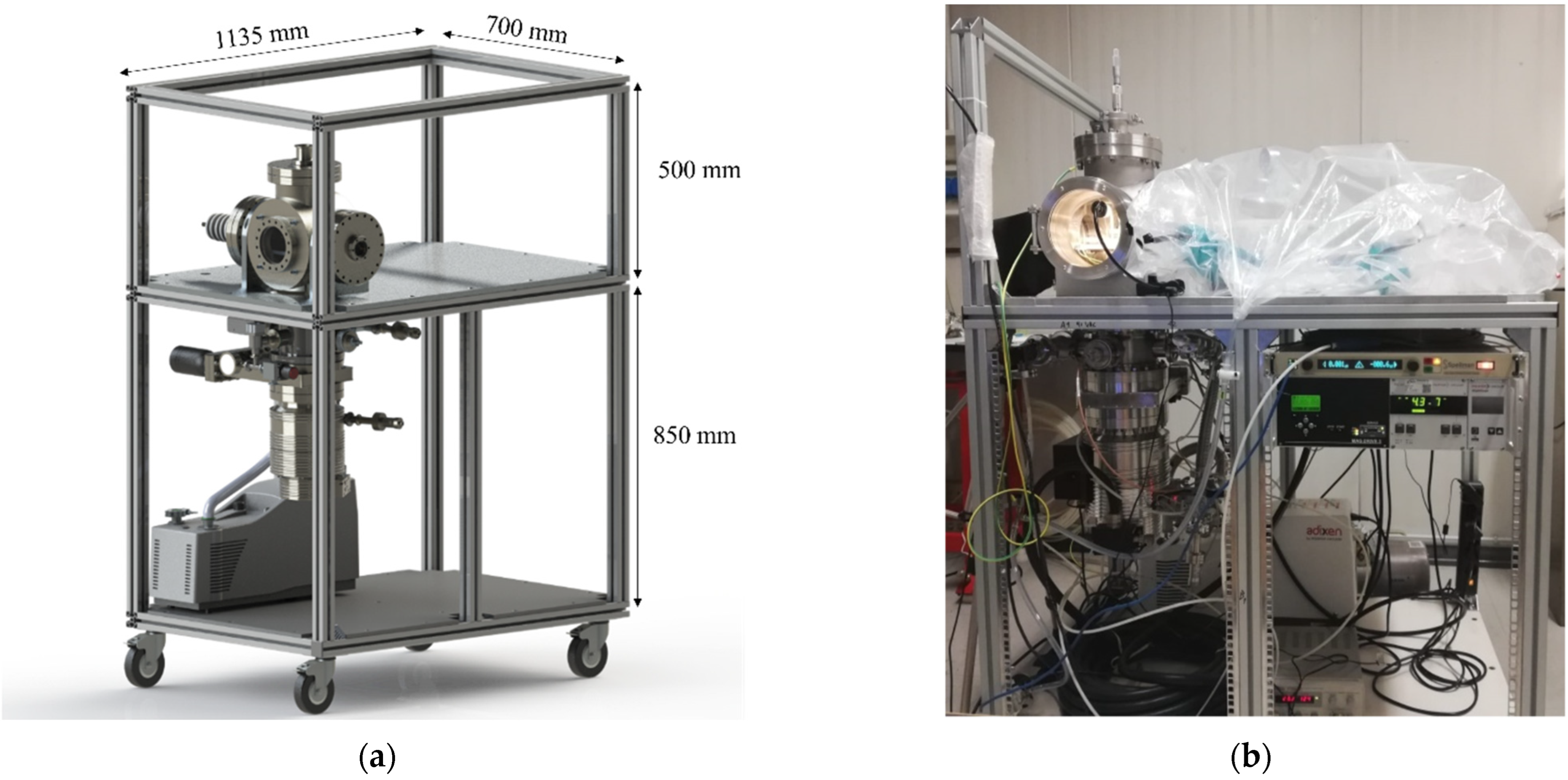
The HIVIPP set-up consists of aluminum profile structure, vacuum system, sample holder, high-voltage power supply controlled by a PC with LabView program, and a camera to visualize the powder motion. In addition, a suitable clamp for easy sample holder manageability has been designed to guarantee the stability of the electrodes (substrates), the cylinder, and the contained powder during assembly. All components may be unmounted, providing greater flexibility for any modification aimed at future upgrade steps. A 3D drawing and a picture of the assembled HIVIPP set-up developed are shown in Figure 1a,b, respectively.
The aluminum profile structure provides a compact system that is easily moved in a laboratory room. The cart is electrically connected to the vacuum chamber and grounded to the building for safety reasons. The working table was used to install a glove-bag and was designed in a way to facilitate installation of a glove-box, in the future, directly connected to the vacuum chamber to manage oxygen-sensitive materials.

2.1. Vacuum System

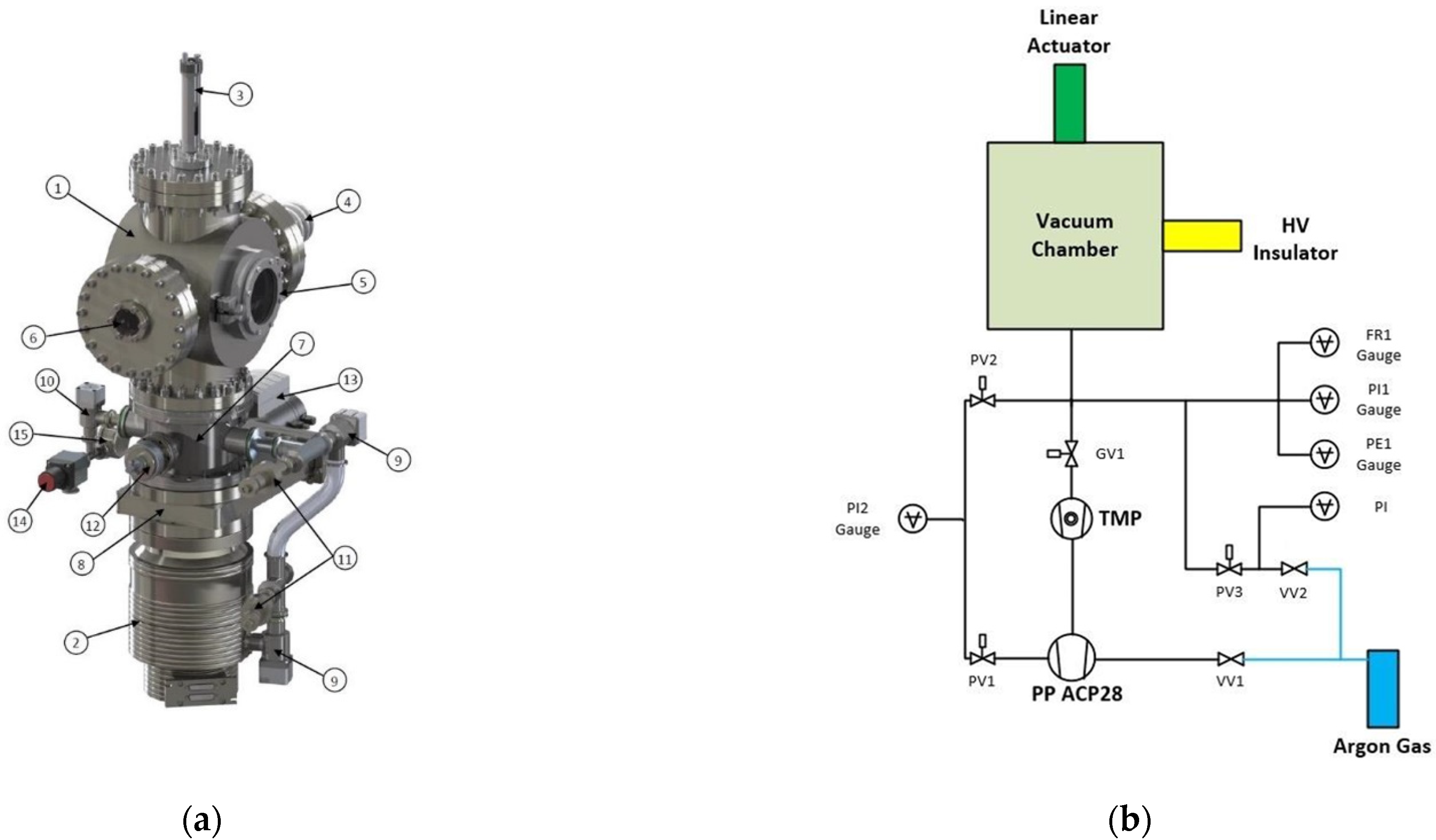
The vacuum chamber is a cylindrical stainless steel (SS) chamber with six 200 CF flanges to connect different components: high voltage insulator, two fixed viewports, DN100 opening viewport for easy access, linear manual actuator for cylinder moving, transitions for other connections (e.g., vacuum gauges, gate valves, etc.).
The schematic representation of the vacuum system is shown in Figure 2 and the description of the items is listed in Table 1.
The pumping system includes two stages: a primary pump (PP) to provide an ultimate pressure of 3 × 10⁻² mbar (model ACP28 by Pfeiffer) and a turbomolecular pump (TMP) (2) with the related controller (model MAG W 600 P by Leybold Vacuum) to obtain an ultimate pressure of 10−8–10−10 mbar. A gate valve (GV1) (8) is used to separate the process chamber (1) from the TMP (2). A metallic grid is installed between the turbomolecular pump and the chamber to prevent any eventual debris from falling into the TMP causing damage. However, changing its position will be considered in the future, for example, on one side of the vacuum chamber. A “transition” (7) between the chamber (1) and the gate valve (8) is installed to allow the connection of pneumatically controlled valves (9, 10) and a set of vacuum meters (11, 12, 13) with the corresponding controllers.
A manual venting valve (14), connected to the argon cylinder, is used for chamber venting (VV1) after deposition. A viewport (6) is installed for visual observation of the powder motion through a monitor-connected BOSCH VBC-255-51 color CCD video camera.
A feedthrough (Allectra LTD) (4) with a maximum sustainable voltage of 60 kV is connected to the high voltage (HV) power supply.
A linear manual actuator (3) is connected to the sample holder system to control the opening of the quartz cylinder (more details are explained in the next section).
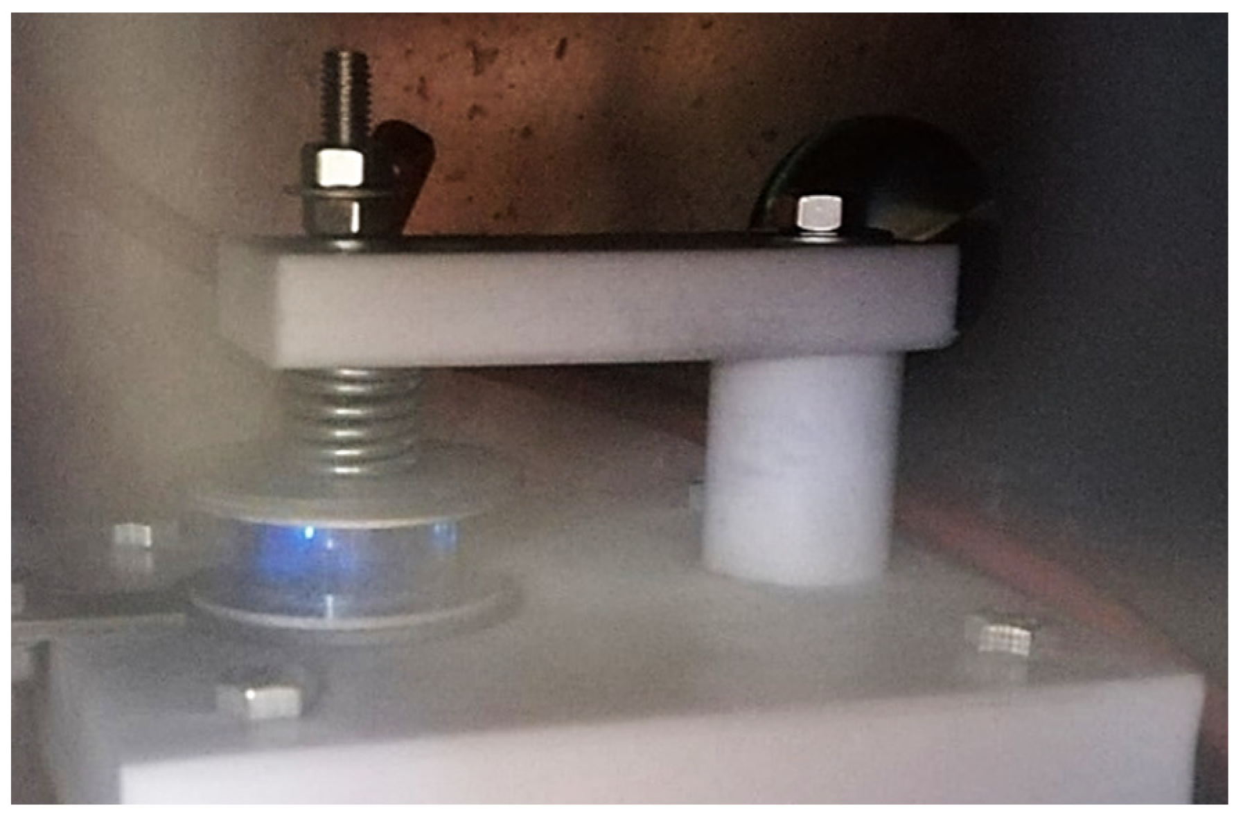
2.2. Sample Holder

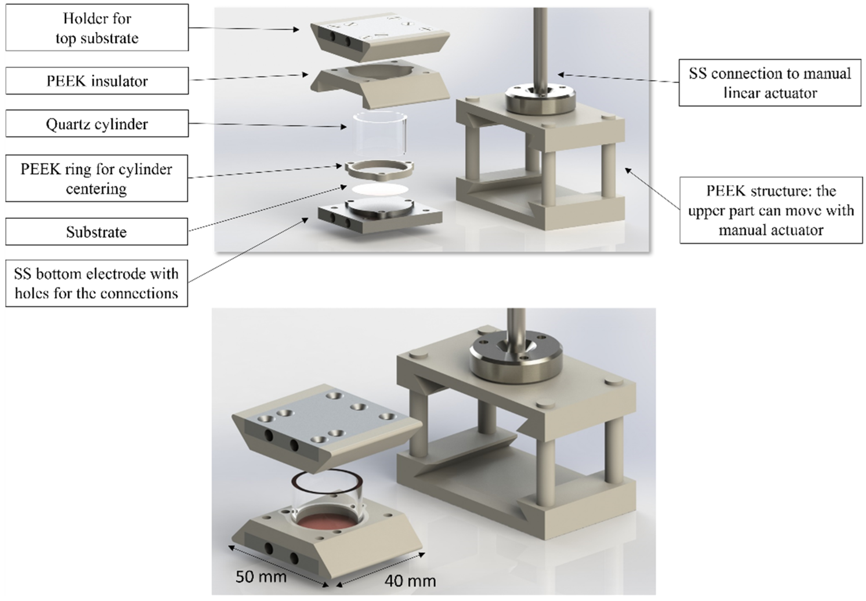
The sample holder for HIVIPP deposition is the crucial component that requires to be properly devised.
The new design guarantees improved handling during the assembly and disassembly steps to minimize the powder losses. The conception and design of the sample holder is represented schematically in Figure 3, and the details of each component are explained below.
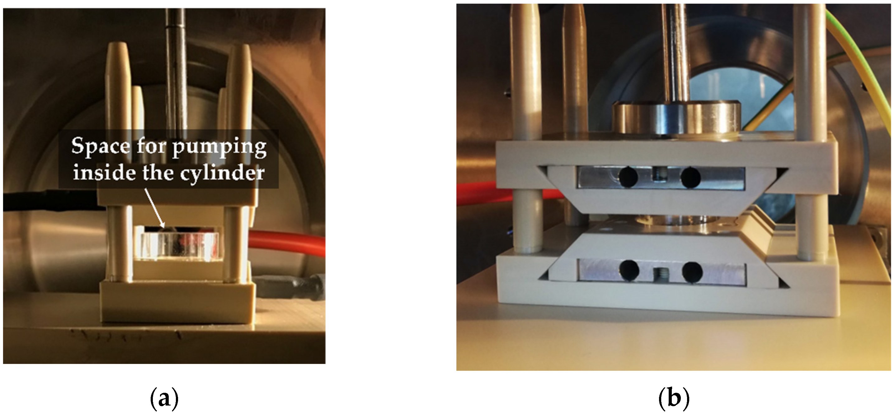
The top and bottom substrate holders are the same and they are composed of an SS electrode on which the substrate is placed, a PEEK insulator and a PEEK ring to fix the substrate and center the quartz cylinder. The cylinder is inserted between the disks to confine the particles in the electrostatic field. M3 PEEK screws are used to assemble each component. By simply changing the ring size, it is possible to host quartz cylinders with different diameters, based upon specific needs (in this work, three sizes were tested: 14-, 18- and 22-mm external diameter corresponding to 10-, 14- and 20-mm internal diameter, respectively). The quartz cylinders were purchased from Helios Italquartz (Milan, Italy). Additionally, a manual linear actuator was connected to the upper part of the sample holder. The PEEK gripping structure allows the top holder to move sliding on vertical rods. This can allow (i) the use of different cylinder heights (in this work, the cylinder height tested ranging from 1 to 2 cm) and (ii) the improvement of vacuum inside the quartz cylinder. To achieve low pressure also in the deposition volume, the top side of the cylinder can be raised 1 mm (i.e., open configuration) during the vacuum pumping step.
The SS electrodes (Top and Bottom) have 4 holes to grasp the assembled sample holder with cylinder using a parallel clamp, besides allowing the insertion of electrodes’ pins with fast connections.
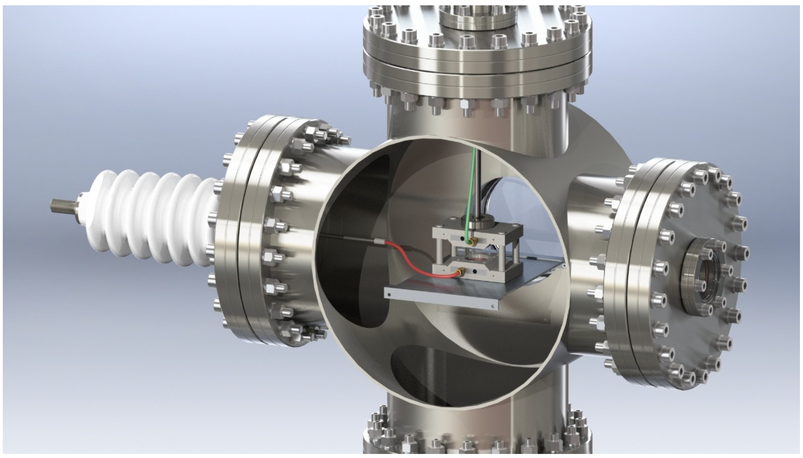
The sample holder with cylinder and powders is placed inside the vacuum chamber (Figure 4) through the CF100 fast-opening viewport using a dedicated parallel clamp to keep the assembly together. This is inserted inside the PEEK gripping structure that is already fixed on a PEEK platform inside the vacuum chamber.
The bottom electrode is connected to the high voltage supply, whereas the top electrode is grounded (connected to the vacuum chamber). However, the electrode connectors can be inverted because the top electrode is insulated from the SS connection of the linear actuator.

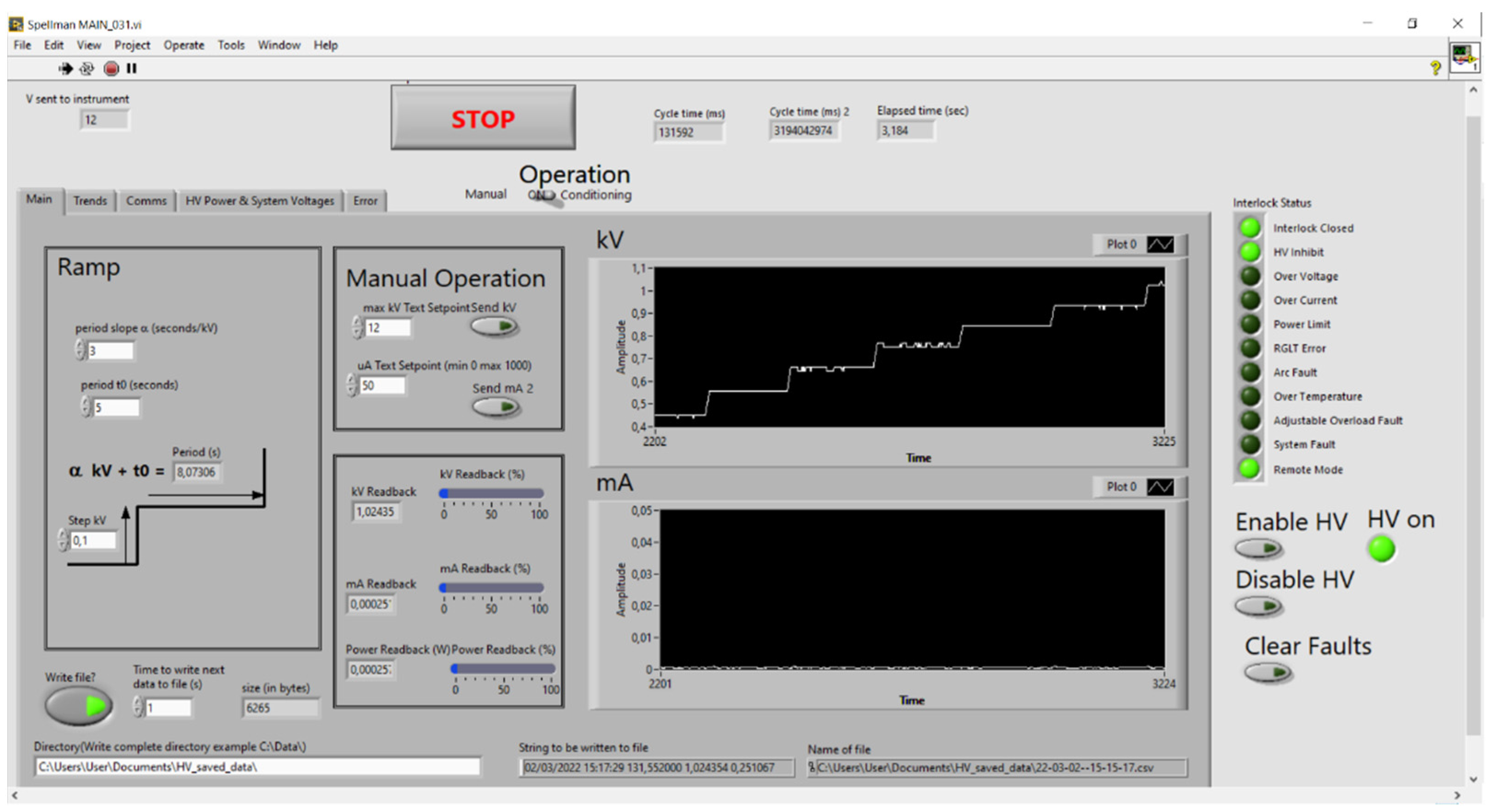
2.3. High Voltage Power Supply and Control with LabView Program

Spellman SL60N60/230 with eSL Ethernet option was used as high voltage power supply (HVPS).
The power supply operation can be controlled from either the local front panel or remotely via the Ethernet connector. Spellman provides a basic demo GUI for the convenience of the user, but in this work, a tailored LabView program was implemented.
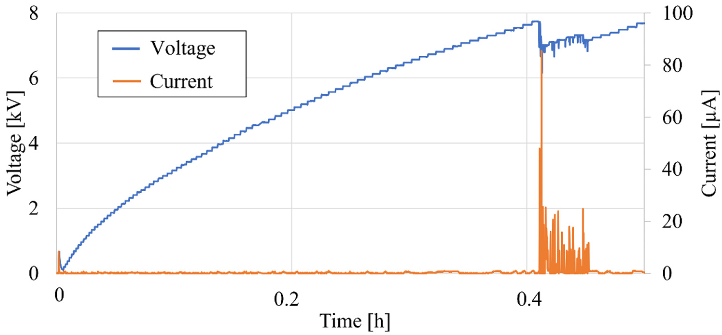
The LabView control system was designed to allow a system conditioning (i.e., avoiding arc discharge from surface), automatization and remote control of the process, and to record the applied current and voltage. The LabView program also allows for full access to the control and diagnostics of the HVPS. The control strategy is based on readings of the actual voltage and current values. The operator can set up a voltage ramp based on a series of steps, whose duration and voltage level increase can be constant, or user-defined. A linear function allows one to have a constant voltage step that holds for a duration that is increasing with the high-voltage value. This is necessary in order to allow for an appropriate conditioning of the apparatus: indeed, the higher the voltage, the longer the conditioning should be. It must be noted that the set voltage of each step is not a priori defined: the voltage step is added to the last read voltage instead of the last set voltage. This allows efficient conditioning, based on the actual status of the experiment. This can lead to unpredictable duration of the ramp, but on the other hand, it allows for a more efficient process restart.
The LabView program is open to the inclusion of a Digital (to) Analog Converter (DAC) to read other parameters from the experiment, such as pressure and temperature. These features could be implemented in the future to allow more complete data analysis or interlock.
The voltage and current values are saved (with a user-defined frequency) in a .csv file for further analysis of the process parameters.

2.4. Visual Observation

Because the process duration can last for several hours, remote control and observation is required. For this purpose, an online method is used. A BOSCH VBC-255-51 color CCD camera, connected with a USB video adapter, allows one to always obtain a view on the screen about the powder motion during the process. Further remote control is realized by TeamViewer.

2.5. Deposition Experiments

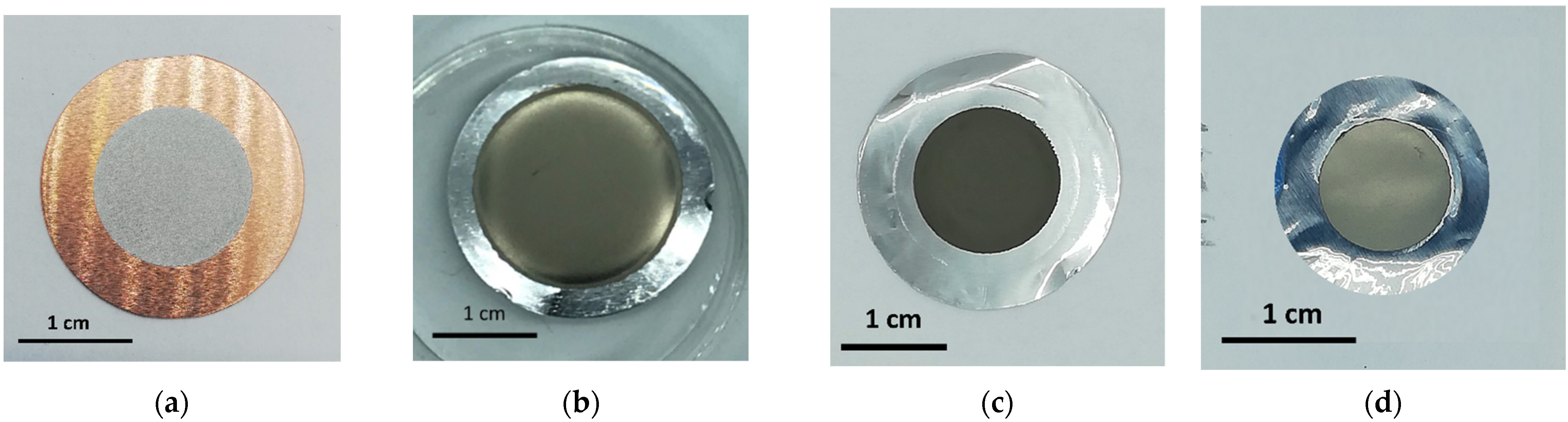
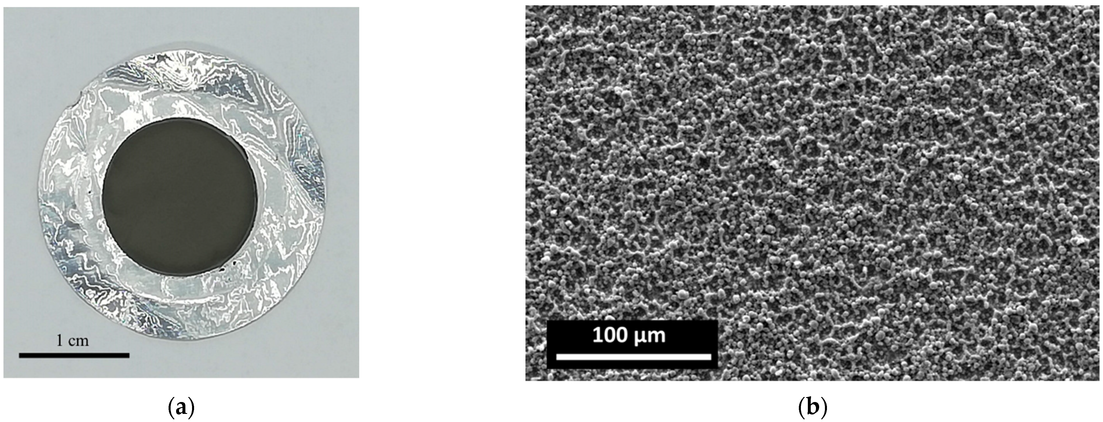
To prove the flexibility of the developed HIVIPP apparatus, several experiments were performed using Mo and Ti powders and Cu and Al substrates, respectively. Four digits analytical balance RADWAG, model AS220.R2, was used to weigh the powder and the substrates before and after deposition, aiming at the preliminary calculation of the areal density deposited.

3. Results

3.1. HIVIPP Apparatus Assembly

The upgraded HIVIPP apparatus installed at INFN-LNL is shown in Figure 1b, and the improvements are described in the following sections.

3.1.1. Sample Holder

The new sample holder offers several advantages over the standard one proposed by Sugai et al., reported in [2,8].
By moving the top part of the sample holder using the manual actuator, the cylinder can be opened during the evacuation step. In this way, the same chamber pressure, read from gauges, is ensured inside the deposition volume. This procedure can be performed for all cylinder heights (from 1 cm to 2 cm), as shown in Figure 5. No detectable powder escape was observed during the cylinder opening procedure in each case. It was observed that an improved vacuum inside the cylinder allows us to minimize arcs or discharges during the deposition at high voltage levels.
The option of choosing different cylinder heights (1–2 cm) can allow one to set the desired electric field for the deposition to better study the HIVIPP process. Furthermore, different substrate thicknesses can be used. It is made possible by the rod with spherical to cone junction, which allows readjustment of the position of the upper part of the PEEK structure as well as uniform movement of the top part that hosts the upper electrode. In this work, 25 µm, 100 µm and 250 µm substrate thicknesses were tested. Because of the PEEK ring, different diameters of the quartz cylinder may be used with the related cylinder centering device on the substrates. As a demonstration of the versatility of the sample holder, in Figure 6, four different depositions performed, by using 10-, 14- and 20-mm internal diameters of the cylinder, and substrate thicknesses of 250, 100 and 25 µm, are shown.
These aspects are particularly advantageous when the sizes of the targets are constrained by the target station where they would be inserted. In addition, the possibility to use different diameters of the cylinder allows us to minimize the consumption of the eventually expensive materials (e.g., the isotopically enriched one) by using a diameter of appropriate size that fits the target dimension and irradiation beam size requested for the specific application.
Furthermore, by keeping the cylinder stable on the bottom substrate, powder loading is easier and safer compared to the older version (Figure 7a,b), and it can be carried out by one person, as shown in Figure 8a.
The top and bottom parts of the sample holder are designed to be inserted into the vacuum chamber through a DN100 viewport, by using a custom designed parallel clamp (Figure 8b). This device is used to easily insert (extract) the top and bottom parts into (from) the gripping structure by one person, and it allows us to preserve the powder not deposited that can be recovered after the deposition process. This is a crucial point, especially in the case where expensive materials are used. The holes inside the SS parts are used for the parallel clamp and for an easy and fast inserting of the electrical connections. In this way, the connections are safer than the standard clamps or screws (see Figure 8b–d).
In Figure 7 and Figure 8, the comparison between the first version of the sample holder and the new one is shown, respectively.

3.1.2. High Voltage Power Supply Control and Remote Observation

High voltage tests were performed to ensure that the thickness of the PEEK insulator was sufficient to avoid discharge effects through it. A voltage level as high as 30 kV was achieved at a 10 mm distance between the electrodes, with the cylinder in vacuum (higher voltages were not tested for safety reasons). However, it is worth noting that a clean environment is essential to avoid electric discharges, and a conditioning of the system is strongly recommended to reach the maximum voltage without discharges. For this reason, a control program based on LabView software was implemented. The conditioning step consists of setting a ramp to increase the voltage as described in the previous section.
The evacuation of the cylinder volume and the possibility to customize the conditioning step are both fundamental aspects of the new HIVIPP apparatus. They would minimize discharges between the electrodes that could be caused by the rapid application of high voltage between the substrates and the consequent rapid generation of gas adsorbed on the microparticles and the surfaces of the substrates, as already declared by [18]. An example of the discharge, which occurred using the first version of the sample holder and a power supply not remotely controlled, can be seen in Figure 9.
In Figure 10, the program interface is shown. The voltage increasing step is set on the left part, and in the right part, the trend of voltage and current are represented.
When a discharge occurred, the current increased and the voltage decreased, but the LabView program allowed us to automatically restore the ramp to reach the maximum set voltage. Figure 11 shows a graph of the current and voltage values during the depositions and a focus on the ramp, discharge, and automatic restoring.

3.2. Repeatability of the Experiments and Efficiency

The repeatability of the process using the developed HIVIPP apparatus was confirmed by several experiments performed. Six depositions were carried out using the same parameters (15 kV, cylinder height 1 cm and internal diameter 14 mm, deposition time 65 h), the same starting material (49Ti with approximately 40% mass of ZrO2 powder of <5 µm size; the presence of ZrO2 is due to the way in which the enriched 49Ti powder was prepared for HIVIPP deposition [19]) and the same substrates (Al foil of 25 µm thickness). The picture of an example deposition is shown in Figure 12a. The mean areal density deposited is 6.41 ± 0.59 and 5.91 ± 0.31 mg/cm2 for the top and bottom deposits, respectively, on a surface area of 1.54 cm2 (deposition diameter was 14 mm).
The resulting thickness variability is in the range of the balance accuracy (±0.2 mg) and the amounts of material deposited on the top and bottom substrates were similar. For each experiment (n = 6), the starting material (31.42 ± 2.10 mg) was not totally deposited but there is a small percentage of losses. Indeed, 60.4 ± 3.7% was deposited, 37.1 ± 3.2% was recovered and only the remained 2.5 ± 1.6% was lost after each deposition. The recovered material was reused for further experiments.
Therefore, considering that not the total starting material is deposited and that there is a small percentage of losses, the deposition efficiency with respect to the starting material was calculated as
ε d e p = P d e p P s t P r e c · 100 % ,
where, P d e p is the deposited powder amount (in mg) on top and bottom substrates, P s t is the starting powder amount (inserted in the cylinder) and P r e c is the recovered powder after deposition. For these experimental conditions, the deposition efficiency resulted to be 96.0 ± 2.6%.
Similarly, the efficiency in terms of recovered material can be calculated following Equation (2):
ε r e c = P r e c P s t P d e p · 100 % ,
and it resulted to be 93.7 ± 3.7%.
From the pictures and scanning electron microscopy (SEM) image in Figure 12b, the deposits resulted uniform, and the microstructure of the deposits reflected the powder size.
Further confirmation of the repeatability of the process was obtained by carrying out seven deposition experiments (no. 14 targets) of pure 49Ti powder (<5 µm), onto Al substrates (25 µm) using 12 kV and 10 h as deposition parameters. In this case, the areal deposited amount of material was 0.45 ± 0.05 mg/cm2 and 0.49 ± 0.04 mg/cm2 for the top and bottom targets, respectively. It can be deduced that the deposition time and the voltage probably influence the deposited amount. The mass thickness indeed resulted lower than those of the experiments described above. Therefore, in this case, considering that the starting material was 20.22 ± 1.57 mg, the percentage of the deposited amount was 7.2 ± 0.5%, the recovered material was 89.7 ± 2.1% and the losses resulted 3.1 ± 2.1%, similar to the previous experiment described. Because the deposited amount was lower, the ε d e p resulted to be 72.1 ± 14.8%, however, ε r e c was 96.6 ± 2.2%. This means that, also in this case, less than 1 mg was lost after each deposition run, confirming that this technique is ideal when a low amount of expensive enriched material, in powder form, is available. The uniformity of the obtained targets was confirmed as well by SEM analysis and Elastic Backscattering Spectroscopy measurements [20]. More details on the manufacturing and analysis of these targets will soon be described in a dedicated article.

4. Discussion and Conclusions

The set-up apparatus described here was developed to study and use the High Energy Vibrational Powder Plating technique for making targets for nuclear physics experiments or applications. Despite its advantages for the realization of targets starting from enriched isotopic materials in powder form, the literature on the High Energy Vibrational Powder Plating technique is anyway not sufficient.
The updated apparatus developed in this work includes the automation of the power supply and the data recording that can allow one to associate the quality of the targets obtained with the evolution of the process and with the parameters used.
The improvements in the HIVIPP apparatus have indeed allowed us to start a deep study on how some selected HIVIPP parameters (i.e., powder size, electric field, cylinder height, powder oxidation, etc.) may influence the thickness and the uniformity of the depositions, keeping other variables constant (e.g., powder and substrate materials, deposition time) to create a model of the process. A set of experiments was carried out within the framework of the E_PLATE project; however, it is beyond the scope of this work to report additional details of this study [21,22]. Until the process is not very well understood, there are always some uncontrollable variables (e.g., environmental humidity, operator, etc.) influencing the depositions. For such a reason, it is important to have a set-up that allows a precise control of the assembly steps and power supply automation to have more reproducible experiments; once these conditions are obtained, the parameters influencing the quality of the targets can be optimized.
We have demonstrated that this kind of HIVIPP set-up is versatile because different substrates and cylinder sizes can be used based on the needs. Furthermore, it can allow us to manufacture reproducible targets using the same powder material, powder size, cylinder heights and substrates (Ti targets), and the loss of the starting material during the target preparation process is about 3%, which corresponds to less than 1 mg.
To conclude, we have confirmed that the HIVIPP technique could be a viable, simple, and material-cost-saving alternative for thin target manufacturing. These results are considerably promising, and they pave the way for the use of the developed HIVIPP system with expensive enriched materials, in metallic powder form, such as 49,50Ti, to manufacture thin homogeneous targets suitable for nuclear cross section measurements.

Author Contributions

Conceptualization, H.S. and S.C.; methodology, H.S., S.C., L.P., P.A. and G.S.; software, P.A.; validation, H.S., S.C., L.P. and P.A.; formal analysis, S.C. and H.S.; investigation, S.C. and H.S.; resources, H.S. and J.E.; data curation, S.C. and H.S.; writing—original draft preparation, S.C.; writing—review and editing, S.C., H.S., G.S., P.A., G.P., L.M. and J.E.; visualization, S.C.; supervision, H.S.; project administration, H.S.; funding acquisition, H.S. All authors have read and agreed to the published version of the manuscript.

Funding

This research was funded by the E_PLATE project CNS5 INFN in the framework of the LARAMED program (funded by the Ministry of Education, University and Research, MUR, Italy), running at Istituto Nazionale di Fisica Nucleare-Laboratori Nazionali di Legnaro (INFN-LNL), Italy.

Institutional Review Board Statement

Not applicable.

Informed Consent Statement

Not applicable.

Data Availability Statement

Not applicable.

Acknowledgments

Authors would like to thank Carlos Rossi Alvarez, Luca Taffarello, and INFN-LNL mechanical workshop for their valuable support in the projects.

Conflicts of Interest

The authors declare no conflict of interest.

References

  1. Stolarz, A. Target Preparation for Research with Charged Projectiles. J. Radioanal. Nucl. Chem. 2014, 299, 913–931. [Google Scholar] [CrossRef] [PubMed] [Green Version]
  2. Sugai, I. An Application of a New Type Deposition Method to Nuclear Target Preparation. Nucl. Instrum. Methods Phys. Res. Sect. A Accel. Spectrometers Detect. Assoc. Equip. 1997, 397, 81–90. [Google Scholar] [CrossRef]
  3. Sugai, I. Target Preparation by Means of the Vibrational Motion of Particles at One Atmosphere. Nucl. Instrum. Methods Phys. Res. Sect. A Accel. Spectrometers Detect. Assoc. Equip. 1999, 438, 58–64. [Google Scholar] [CrossRef]
  4. Sugai, I.; Takeda, Y.; Kawakami, H.; Nagai, Y.; Ohta, N. Improvement of Thickness and Uniformity of Isotopically Enriched 12C Targets on Backings by the HIVIPP Method. Nucl. Instrum. Methods Phys. Res. Sect. A Accel. Spectrometers Detect. Assoc. Equip. 2008, 590, 164–170. [Google Scholar] [CrossRef]
  5. Sugai, I.; Takeda, Y.; Oyaizu, M.; Kawakami, H.; Sasa, K.; Ishii, S.; Shima, K. First Results of Target Preparation by the HIVIPP Method in Pressures Higher than One Bar. Nucl. Instrum. Methods Phys. Res. Sect. A Accel. Spectrometers Detect. Assoc. Equip. 2008, 590, 83–90. [Google Scholar] [CrossRef]
  6. Sugai, I.; Takeda, Y.; Kawakami, H. Production of Uniform and Thick Enriched Isotopic Te Targets by Means of the HIVIPP Method. Nucl. Instrum. Methods Phys. Res. Sect. A Accel. Spectrometers Detect. Assoc. Equip. 2010, 613, 407–411. [Google Scholar] [CrossRef]
  7. Sugai, I.; Takeda, Y.; Kawakami, H.; Ohta, N.; Makii, H.; Miyatake, H. Adhesion Improvement of HIVIPP 12C Targets on Au Backings. Nucl. Instrum. Methods Phys. Res. Sect. A Accel. Spectrometers Detect. Assoc. Equip. 2011, 655, 24–33. [Google Scholar] [CrossRef]
  8. Skliarova, H.; Cisternino, S.; Pranovi, L.; Mou, L.; Pupillo, G.; Rigato, V.; Rossi Alvarez, C. HIVIPP Deposition and Characterization of Isotopically Enriched 48Ti Targets for Nuclear Cross-Section Measurements. Nucl. Instrum. Methods Phys. Res. Sect. A Accel. Spectrometers Detect. Assoc. Equip. 2020, 981, 164371. [Google Scholar] [CrossRef]
  9. Pupillo, G.; Fontana, A.; Canton, L.; Haddad, F.; Skliarova, H.; Cisternino, S.; Martini, P.; Pasquali, M.; Boschi, A.; Esposito, J.; et al. Preliminary Results of the PASTA Project. Nuovo Cim. C 2019, 42, 1–4. [Google Scholar] [CrossRef]
  10. Pupillo, G.; Mou, L.; Boschi, A.; Calzaferri, S.; Canton, L.; Cisternino, S.; De Dominicis, L.; Duatti, A.; Fontana, A.; Haddad, F.; et al. Production of 47Sc with Natural Vanadium Targets: Results of the PASTA Project. J. Radioanal. Nucl. Chem. 2019, 322, 1711–1718. [Google Scholar] [CrossRef]
  11. Technological Research (CSN5)—Home INFN Legnaro. Available online: https://www.lnl.infn.it/en/technological-research-csn5/ (accessed on 10 May 2022).
  12. Esposito, J.; Bettoni, D.; Boschi, A.; Calderolla, M.; Cisternino, S.; Fiorentini, G.; Keppel, G.; Martini, P.; Maggiore, M.; Mou, L.; et al. LARAMED: A Laboratory for Radioisotopes of Medical Interest. Molecules 2019, 24, 20. [Google Scholar] [CrossRef] [PubMed] [Green Version]
  13. Pupillo, G.; Antonini, P.; Calderolla, M.; Calore, A.; Bettoni, D.; Boschi, A.; Cisternino, S.; Duatti, A.; Evangelisti, F.; Favaron, P.; et al. The Laramed Project at LNL: 67Cu and 47Sc Production for Theranostic Applications. AIP Conf. Proc. 2020, 2295, 020001. [Google Scholar] [CrossRef]
  14. Cisternino, S.; Cazzola, E.; Skliarova, H.; Amico, J.; Malachini, M.; Gorgoni, G.; Anselmi-Tamburini, U.; Esposito, J. Target Manufacturing by Spark Plasma Sintering for Efficient 89Zr Production. Nucl. Med. Biol. 2022, 104–105, 38–46. [Google Scholar] [CrossRef] [PubMed]
  15. Skliarova, H.; Cisternino, S.; Cicoria, G.; Cazzola, E.; Gorgoni, G.; Marengo, M.; Esposito, J. Cyclotron Solid Targets Preparation for Medical Radionuclides Production in the Framework of LARAMED Project. J. Phys. Conf. Ser. 2020, 1548, 012022. [Google Scholar] [CrossRef]
  16. Skliarova, H.; Cisternino, S.; Cicoria, G.; Marengo, M.; Cazzola, E.; Gorgoni, G.; Palmieri, V. Medical Cyclotron Solid Target Preparation by Ultrathick Film Magnetron Sputtering Deposition. Instruments 2019, 3, 21. [Google Scholar] [CrossRef] [Green Version]
  17. Skliarova, H.; Buso, P.; Carturan, S.; Rossi Alvarez, C.; Cisternino, S.; Martini, P.; Boschi, A.; Esposito, J. Recovery of Molybdenum Precursor Material in the Cyclotron-Based Technetium-99m Production Cycle. Instruments 2019, 3, 17. [Google Scholar] [CrossRef] [Green Version]
  18. Sugai, I. Method of Coating a Substrate with a Coating Material by Vibrating Charged Particles with an Electric Field. U.S. Patent 5445852A, 29 August 1995. [Google Scholar]
  19. Cisternino, S.; Mou, L.; Pupillo, G. Cryomilling of Ti Metal Powder for HIVIPP Deposition. LNL Annual Report 2021; 2022, INFN-LNL-266(2022) ISSN1828-8561, 65. Available online: https://www1.lnl.infn.it/~annrep/read_ar/2021/index.htm (accessed on 26 July 2022).
  20. Palmetshofer, L. Rutherford Backscattering Spectroscopy (RBS). In Surface and Thin Film Analysis; Friedbacher, G., Bubert, H., Eds.; John Wiley & Sons, Ltd.: Weinheim, Germany, 2011; pp. 191–202. ISBN 978-3-527-63692-1. [Google Scholar]
  21. Cisternino, S.; Facco, P.; Skliarova, H. Experimental Data Exploratory Analysis of HIVIPP Process within E-PLATE Project. LNL Annual Report INFN-LNL 2019; 2020, INFN-LNL-259(2020) ISSN1828-8561, 89. Available online: https://www1.lnl.infn.it/~annrep/read_ar/2019/index_contrib.htm (accessed on 26 July 2022).
  22. Antonini, P.; Campostrini, M.; Cisternino, S.; Facco, P.; Mou, L.; Pranovi, L.; Pupillo, G.; Rigato, V.; Rossi, C.; Sciacca, G.; et al. “E-PLATE: Electrostatic Powders PLating for Accelerator TargEt” Project Status Report. Annual Report INFN-LNL 2019; 2020, INFN-LNL-259(2020) ISSN1828-8561, 185. Available online: https://www1.lnl.infn.it/~annrep/read_ar/2019/index_contrib.htm (accessed on 26 July 2022).
Figure 1. The HIVIPP apparatus developed in this work: (a) 3D assembly; (b) picture of the set-up installed at INFN-LNL for the LARAMED project.
Instruments 06 00023 g001
Figure 2. (a) Rendering of the assembled vacuum system, whose numbered components are described in Table 1; (b) vacuum system scheme.
Instruments 06 00023 g002
Figure 3. Rendering of the sample holder with the description of each component.
Instruments 06 00023 g003
Figure 4. Rendering of the sample holder in the vacuum chamber, fixed to the PEEK gripping structure, the electrodes connected to the sample holder, and the feedthrough on the left.
Instruments 06 00023 g004
Figure 5. Open and closed cylinder with heights of 1 cm (a,b), and 2 cm (c,d).
Instruments 06 00023 g005aInstruments 06 00023 g005b
Figure 6. (a) Deposition area on Ø14 mm, 250 µm substrate (Cu) thickness; (b) deposition area on Ø20 mm, 100 µm substrate (Al) thickness; (c) deposition area on Ø14 mm and (d) Ø10 mm using 25 µm substrate (Al) thickness.
Instruments 06 00023 g006
Figure 7. First version of the sample holder according to the design by I. Sugai [2]: (a) picture of assembled sample-holder; (b) assembly step by two people.
Instruments 06 00023 g007
Figure 8. New design of the sample holder: (a) loading of the powder in the cylinder; (b) top and bottom parts kept together by the parallel clamp before insertion or after extraction; fixation of the top and bottom parts in the gripping structure inside the vacuum chamber, in the case of 1 cm (c) and 2 cm (d) cylinder from different points of view.
Instruments 06 00023 g008
Figure 9. Undesired discharge between the electrodes. The picture was taken from the viewport of the vacuum chamber during a process using the old sample holder.
Instruments 06 00023 g009
Figure 10. Interface of the LabView program: on the left there is the main menu to set the parameters; on the right there is the trend of the voltage and the current values during the beginning of an experiment.
Instruments 06 00023 g010
Figure 11. Focus on the voltage (blue line) and current (orange line) vs. time while a discharge occurs.
Instruments 06 00023 g011
Figure 12. (a) Picture of the target Ti onto Al. (b) SEM image of the deposit.
Instruments 06 00023 g012
Table 1. Description of the vacuum system components represented in Figure 2.
Item N.DescriptionQuantity
1Vacuum chamber1
2TMP1
325 mm Manual Actuator1
460 kV HV Insulator1
5Window Viewport CF1001
6Viewport CF401
7Flange Adapter CF160-CF40-KF401
8Gate Valve CF160 (24 V Electro-Pneumatic Actuator)1
9Angle Valve KF25 (24 V Electro-Pneumatic Actuator)2
10Angle Valve KF16 (24 V Electro-Pneumatic Actuator)1
11Pirani Vacuum Gauge 2
12Penning Vacuum Gauge1
13Full Range Spare Gauge1
14Manual Venting Valve1
15Analogic Pressure Indicator 1
Publisher’s Note: MDPI stays neutral with regard to jurisdictional claims in published maps and institutional affiliations.

