
Direct Visualization of Cervical Interlaminar Epidural Injections Using Sonography


Abstract
:1. Introduction
2. Materials and Methods
2.1. Patients
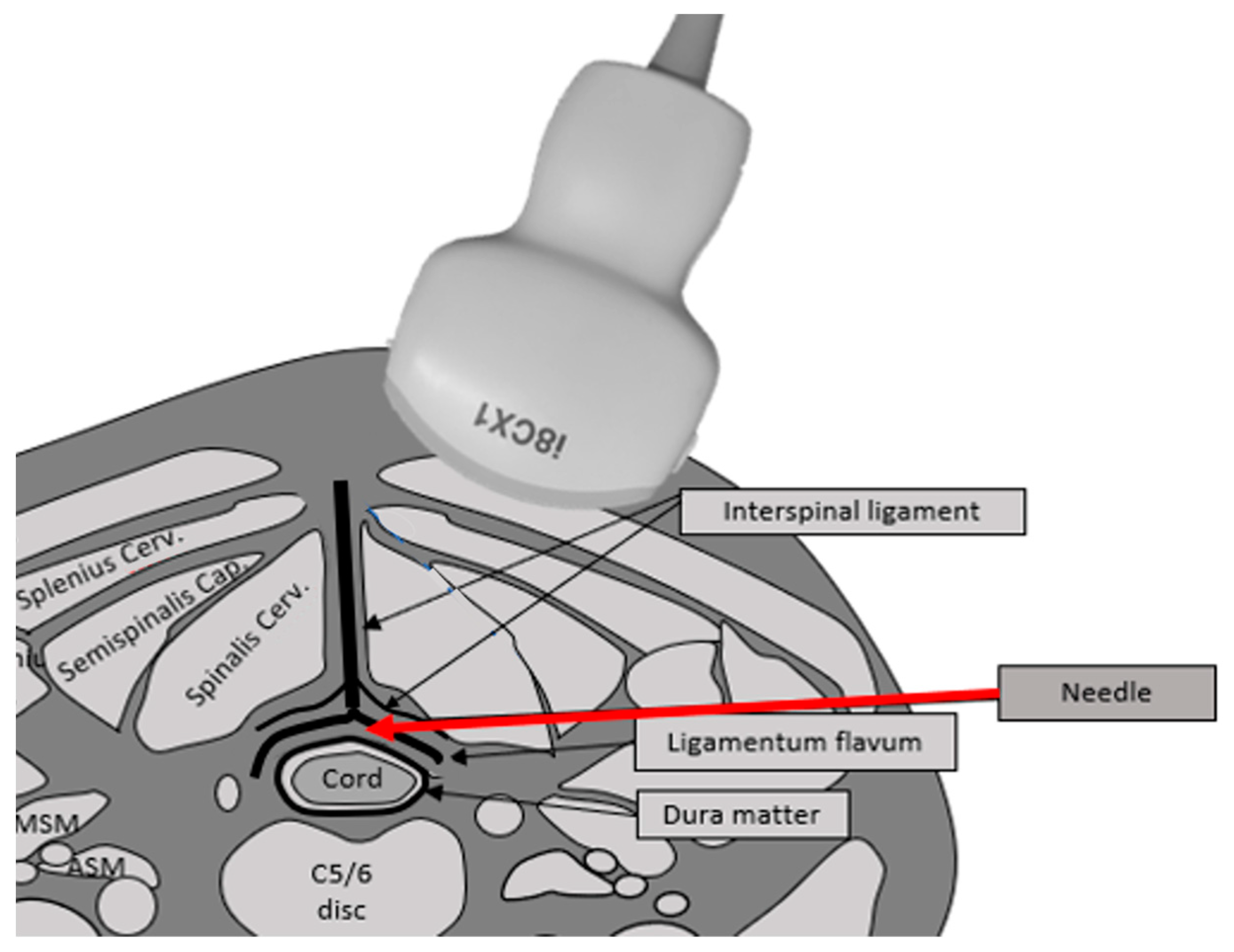
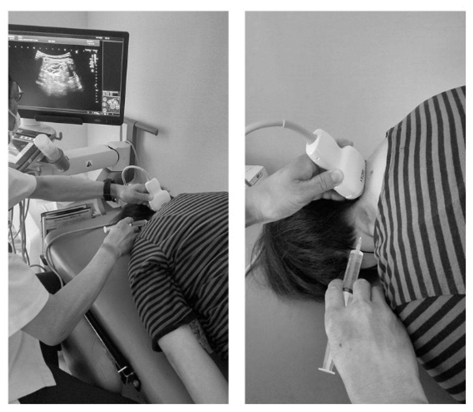
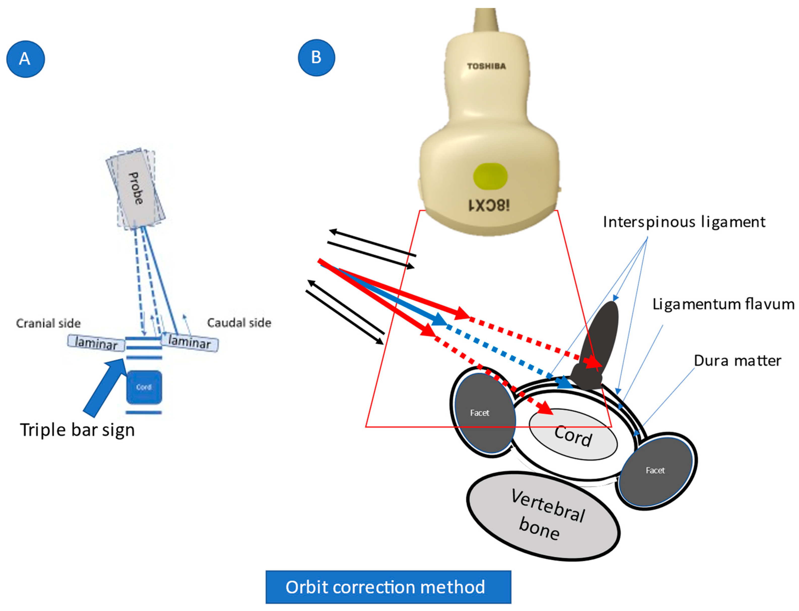
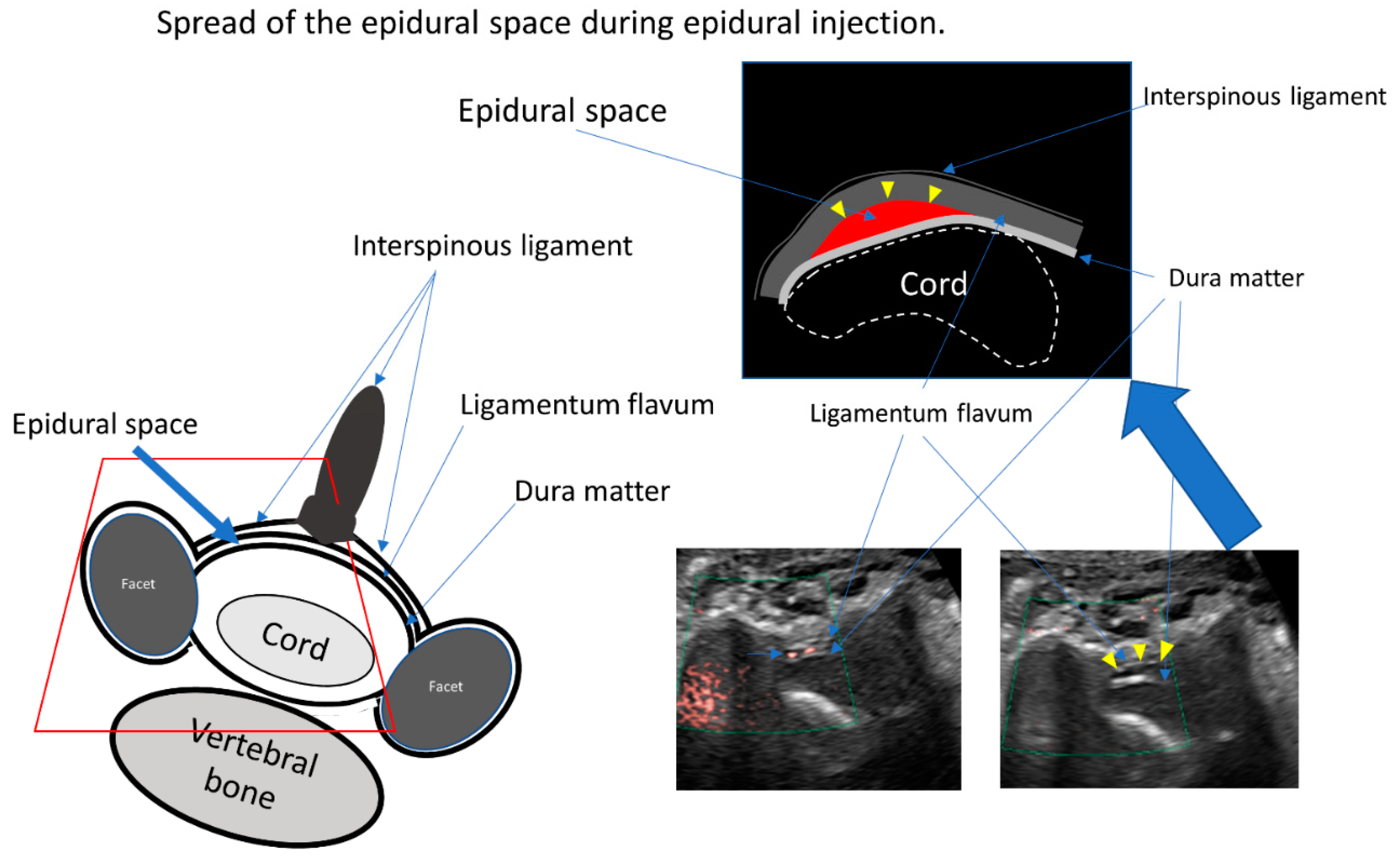
2.2. US-Guided CEDI
2.3. CT Epidurography
2.4. Pain Intensity
2.5. Functional Ability
3. Results
3.1. Representative Cases
3.1.1. Case 4
3.1.2. Case 5
3.1.3. Case 9
4. Discussion
5. Conclusions
Supplementary Materials
Author Contributions
Funding
Institutional Review Board Statement
Informed Consent Statement
Data Availability Statement
Acknowledgments
Conflicts of Interest
References
- Stout, A. Epidural Steroid Injections for Cervical Radiculopathy. Phys. Med. Rehabil. Clin. N. Am. 2011, 22, 149–159. [Google Scholar] [CrossRef] [PubMed]
- Abbasi, A.; Malhotra, G.; Malanga, G.; Elovic, E.P.; Kahn, S. Complications of interlaminar cervical epidural steroid injections: A review of the literature. Spine 2007, 32, 2144–2151. [Google Scholar] [CrossRef] [PubMed]
- Huston, C.W. Cervical epidural steroid injections in the management of cervical radiculitis: Interlaminar versus transforaminal. A review. Curr. Rev. Musculoskelet. Med. 2009, 2, 30–42. [Google Scholar] [CrossRef] [PubMed]
- Provenzano, D.A.; Fanciullo, G. Cervical transforaminal epidural steroid injections: Should we be performing them? Reg. Anesth. Pain Med. 2007, 32, 168, author reply 169–170. [Google Scholar] [CrossRef]
- Kim, J.; Kim, K.; Lee, M.; Kim, S. Correlation Between Intravascular Injection Rate, Pain Intensity, and Degree of Cervical Neural Foraminal Stenosis During a Cervical Transforaminal Epidural Block. J. Pain Res. 2021, 14, 3017–3023. [Google Scholar] [CrossRef]
- Maeda, M.; Maeda, N.; Masuda, K.; Nagano, T.; Tanaka, Y. Ultrasound-Guided Cervical Intervertebral Disc Injection without Fluoroscopy. J. Ultrasound Med. 2022, in press. [Google Scholar] [CrossRef]
- Kim, Y.U.; Kim, D.; Park, J.Y.; Choi, J.-H.; Kim, J.H.; Bae, H.-Y.; Joo, E.-Y.; Suh, J.H. Method to Reduce the False-Positive Rate of Loss of Resistance in the Cervical Epidural Region. Pain Res. Manag. 2016, 2016, 9894054. [Google Scholar] [CrossRef]
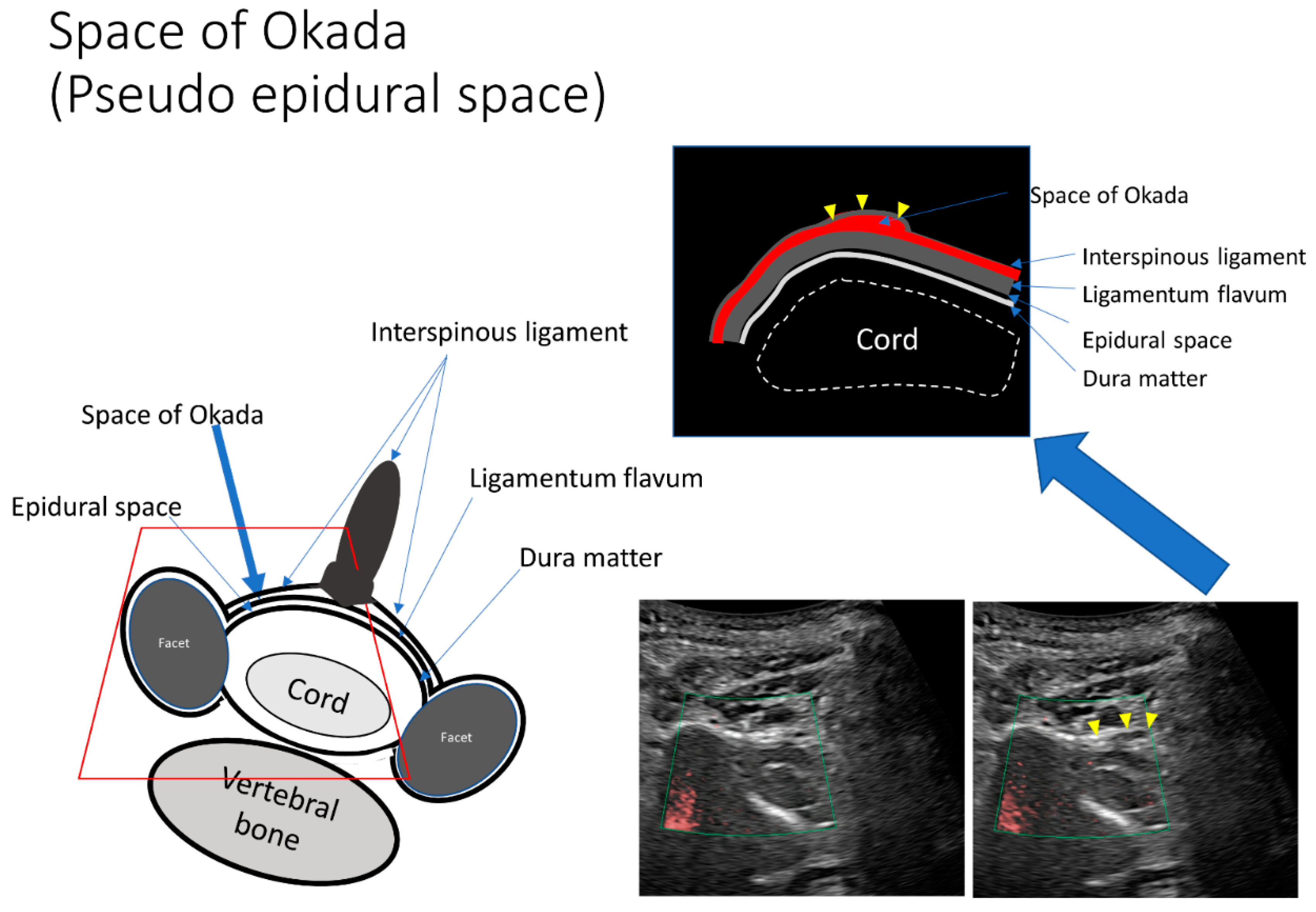
- Okada, K. Studies on the cervical facet joints using arthrography of the cervical facet joint. Nihon Seikeigeka Gakkai Zasshi 1981, 55, 563–580. (In Japanese) [Google Scholar]
- Lustig, J.P.; Aubry, S.; Vidal, C.; Pazart, L.; Moreau-Gaudry, A.; Bricault, I. Body interventional procedures: Which is the best method for CT guidance? Eur. Radiol. 2020, 30, 1593–1600. [Google Scholar] [CrossRef]
- Ha, S.O.; Kim, D.Y.; Sohn, Y.D. Clinical characteristics of adverse reactions to nonionic low osmolality contrast media in patients transferred from the CT room to the emergency room. SpringerPlus 2016, 5, 929. [Google Scholar] [CrossRef]
- Wylie, J.D.; Jenkins, P.A.; Beckmann, J.T.; Peters, C.L.; Aoki, S.K.; Maak, T.G. Computed Tomography Scans in Patients with Young Adult Hip Pain Carry a Lifetime Risk of Malignancy. Arthrosc. J. Arthrosc. Relat. Surg. 2018, 34, 155–163.e3. [Google Scholar] [CrossRef] [PubMed]
- Takeshita, K.; Oshima, Y.; Ono, T.; Kato, S.; Hosono, N.; Kawaguchi, Y.; Hasegawa, K.; Isomura, T.; Oshina, M.; Oda, T.; et al. Validity, reliability and responsiveness of the Japanese version of the Neck Disability Index. J. Orthop. Sci. 2013, 18, 14–21. [Google Scholar] [CrossRef]
- Kranz, P.; Raduazo, P.; Gray, L.; Kilani, R.; Hoang, J. CT Fluoroscopy-Guided Cervical Interlaminar Steroid Injections: Safety, Technique, and Radiation Dose Parameters. Am. J. Neuroradiol. 2012, 33, 1221–1224. [Google Scholar] [CrossRef] [PubMed]
- Amrhein, T.J.; Parivash, S.N.; Gray, L.; Kranz, P.G. Incidence of Inadvertent Dural Puncture During CT Fluoroscopy–Guided Interlaminar Epidural Corticosteroid Injections in the Cervical Spine: An Analysis of 974 Cases. Am. J. Roentgenol. 2017, 209, 656–661. [Google Scholar] [CrossRef] [PubMed]
- Hogan, Q.H. Epidural anatomy examined by cryomicrotome section. Influence of age, vertebral level, and disease. Reg. Anesth. J. Neural Blockade Obstet. Surg. Pain Control. 1996, 21, 395–406. [Google Scholar]
- House, L.M.; Barrette, K.; Mattie, R.; McCormick, Z.L. Cervical epidural steroid injection: Techniques and evidence. Phys. Med. Rehabil. Clin. 2018, 29, 1–17. [Google Scholar] [CrossRef]
- Moreno, B.; Barbosa, J. Ultrasound-Guided Procedures in the Cervical Spine. Cureus 2021, 13, e20361. [Google Scholar] [CrossRef]
- Hurley, R.W.; Adams, M.C.; Barad, M.; Bhaskar, A.; Bhatia, A.; Chadwick, A.; Deer, T.R.; Hah, J.; Hooten, W.M.; Kissoon, N.R.; et al. Consensus practice guidelines on interventions for cervical spine (facet) joint pain from a multispecialty international working group. Pain Med. 2022, 47, 3–59. [Google Scholar] [CrossRef]
- Lirk, P.; Kolbitsch, C.; Putz, G.; Colvin, J.; Colvin, H.P.; Lorenz, I.; Keller, C.; Kirchmair, L.; Rieder, J.; Moriggl, B. Cervical and High Thoracic Ligamentum Flavum Frequently Fails to Fuse in the Midline. Anesthesiology 2003, 99, 1387–1390. [Google Scholar] [CrossRef]
- Maeda, M.; Maeda, N.; Nagano, T. Diagnosis of sternal fracture using static and stressed ultrasonography. J. Jpn. Soc. Orthop. Ultrason. 2018, 30, 210–219. [Google Scholar]
- Kranz, P.; Joshi, A.; Roy, L.; Choudhury, K.; Amrhein, T. Inadvertent Intrafacet Injection during Lumbar Interlaminar Epidural Steroid Injection: A Comparison of CT Fluoroscopic and Conventional Fluoroscopic Guidance. Am. J. Neuroradiol. 2016, 38, 398–402. [Google Scholar] [CrossRef] [PubMed]
- Kim, M.J.; Choi, Y.S.; Suh, H.J.; Kim, Y.J.; Noh, B.J. Unintentional lumbar facet joint injection guided by fluoroscopy during interlaminar epidural steroid injection: A retrospective analysis. Korean J. Pain 2018, 31, 87–92. [Google Scholar] [CrossRef] [PubMed]
- Riveros-Perez, E.; Albo, C.; Jimenez, E.; Cheriyan, T.; Rocuts, A. Color your epidural: Color flow Doppler to confirm labor epidural needle position. Minerva Anestesiol. 2019, 85, 376–383. [Google Scholar] [CrossRef] [PubMed]
- Zhang, X.; Shi, H.; Zhou, J.; Xu, Y.; Pu, S.; Lv, Y.; Wu, J.; Cheng, Y.; Du, D. The effectiveness of ultrasound-guided cervical transforaminal epidural steroid injections in cervical radiculopathy: A prospective pilot study. J. Pain Res. 2018, 12, 171–177. [Google Scholar] [CrossRef]


| Case | Age (years) | Sex | Body Mass Index (kg/m2) | Diagnosis |
|---|---|---|---|---|
| 1 | 24 | M | 24 | Th1/2 Disc herniation |
| 2 | 45 | M | 31.2 | C2/3, 5/6, 6/7 Disc herniation |
| 3 | 51 | M | 20.9 | Cervical discopathy |
| 4 | 73 | F | 19.3 | Cervical canal stenosis |
| 5 | 73 | M | 24.7 | Cervical canal stenosis |
| 6 | 63 | F | 28.8 | C5/6 Disc herniation |
| 7 | 74 | F | 21.4 | Cervical canal stenosis |
| 8 | 35 | M | 26.2 | Cervical discopathy |
| 9 | 23 | M | 21 | Cervical discopathy |
| Case | Injection Site | Pre Visual Analog Scale Scores | Post Visual Analog Scale Scores | Neck Disability Index | Additional Injection (Times) | Additional Opioid Consumption (Times) |
|---|---|---|---|---|---|---|
| 1 | C6/7 | 10 | 2.5 | 40%→4% | 0 | 0 |
| 2 | C5/6 | 10 | 5 | 70%→26% | 0 | 0 |
| 3 | C5/6 | 4 | 2 | 16%→20% | 0 | 0 |
| 4 | C4/5 | 10 | 2 | 94%→34% | 20 | 0 |
| 5 | C5/6 | 5.9 | 0 | 8%→2% | 0 | 0 |
| 6 | C4/5 | 9 | 0 | 48%→10% | 0 | 0 |
| 7 | C3/4 | 10 | 5 | 54%→28% | 4 | 0 |
| 8 | C6/7 | 9 | 0 | 28%→4% | 4 | 0 |
| 9 | C5/6 | 6.5 | 0 | 42%→12% | 2 | 0 |
Publisher’s Note: MDPI stays neutral with regard to jurisdictional claims in published maps and institutional affiliations. |
© 2022 by the authors. Licensee MDPI, Basel, Switzerland. This article is an open access article distributed under the terms and conditions of the Creative Commons Attribution (CC BY) license (https://creativecommons.org/licenses/by/4.0/).
Share and Cite
Maeda, N.; Maeda, M.; Tanaka, Y. Direct Visualization of Cervical Interlaminar Epidural Injections Using Sonography. Tomography 2022, 8, 1869-1880. https://doi.org/10.3390/tomography8040157
Maeda N, Maeda M, Tanaka Y. Direct Visualization of Cervical Interlaminar Epidural Injections Using Sonography. Tomography. 2022; 8(4):1869-1880. https://doi.org/10.3390/tomography8040157
Chicago/Turabian StyleMaeda, Nana, Manabu Maeda, and Yasuhito Tanaka. 2022. "Direct Visualization of Cervical Interlaminar Epidural Injections Using Sonography" Tomography 8, no. 4: 1869-1880. https://doi.org/10.3390/tomography8040157