
Deep Learning Vision System for Quadruped Robot Gait Pattern Regulation


Abstract
:1. Introduction
2. Related Work
2.1. Automatic Terrain Identification Robotic Systems
2.1.1. Identification Based on Contact Sensors
2.1.2. Identification Based on Visual Perception
2.2. Gait Pattern Adjustment of Bioinspired Quadruped Robots
3. Methodology
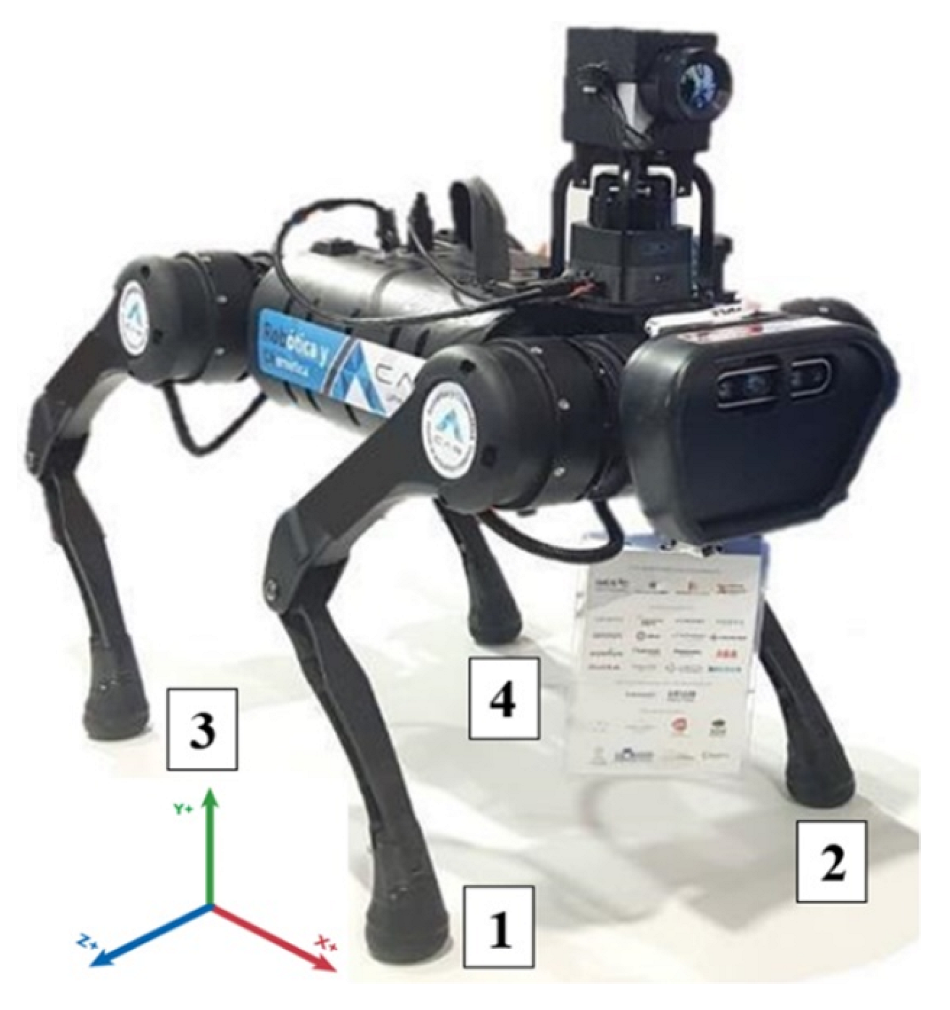
3.1. Materials
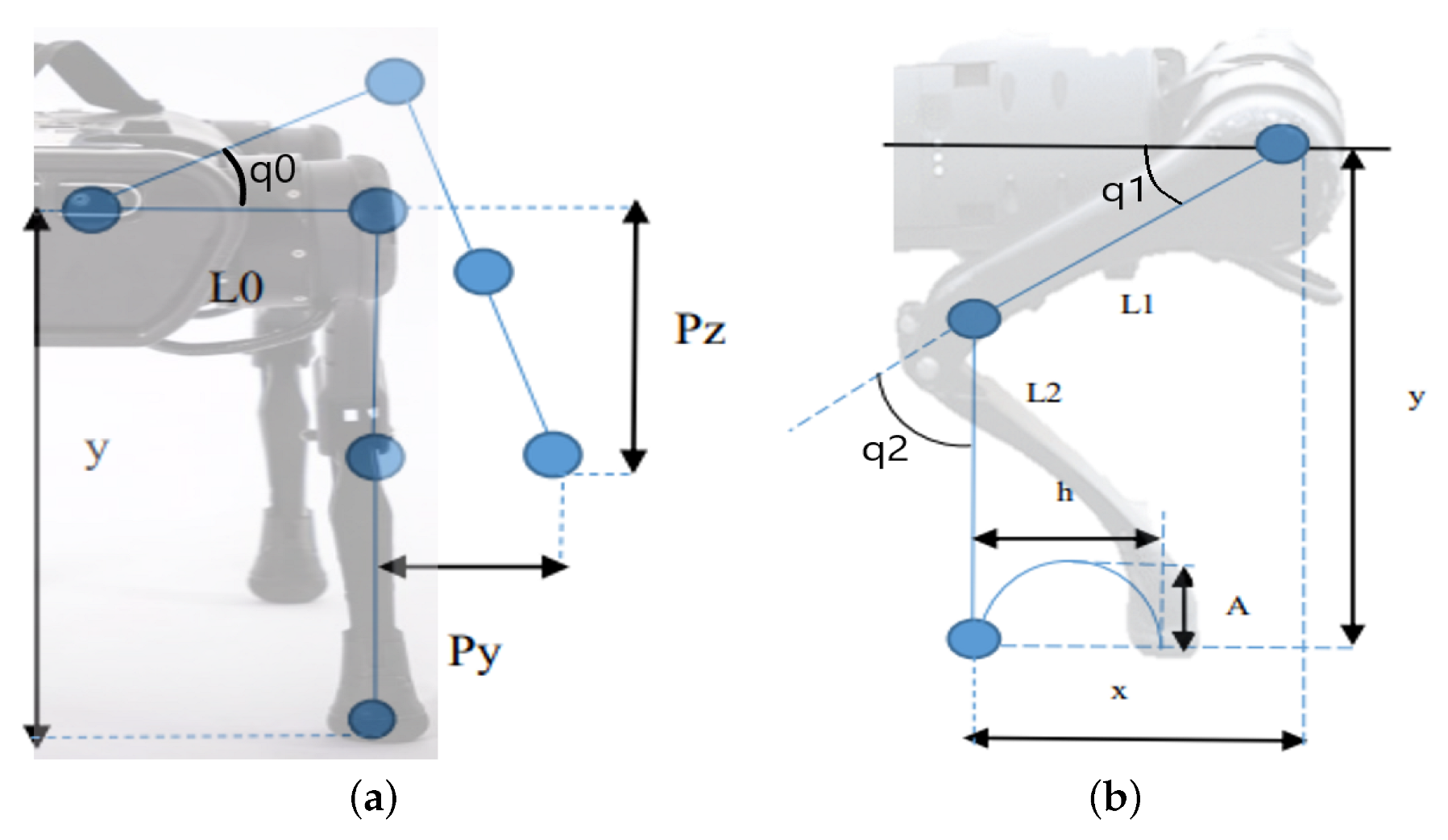
3.2. Kinematic Modeling of the Legs
Iterative Configuration of Gait Patterns
3.3. Test Environments and Parameters
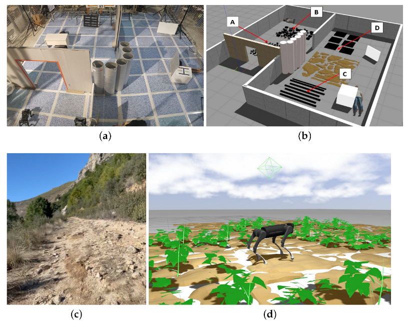
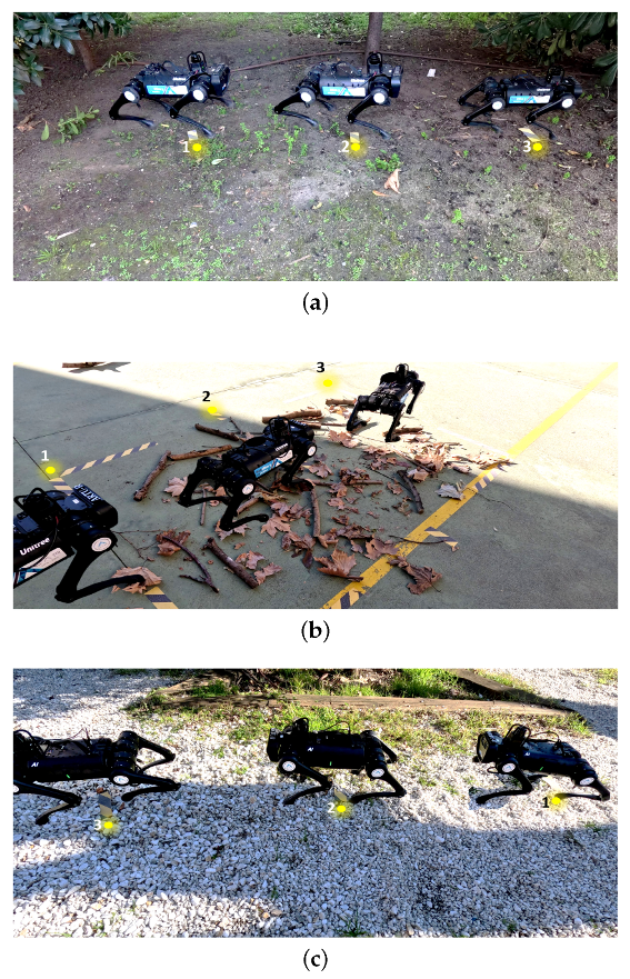
3.3.1. Simulated and Real Environments
3.3.2. Type of Tests
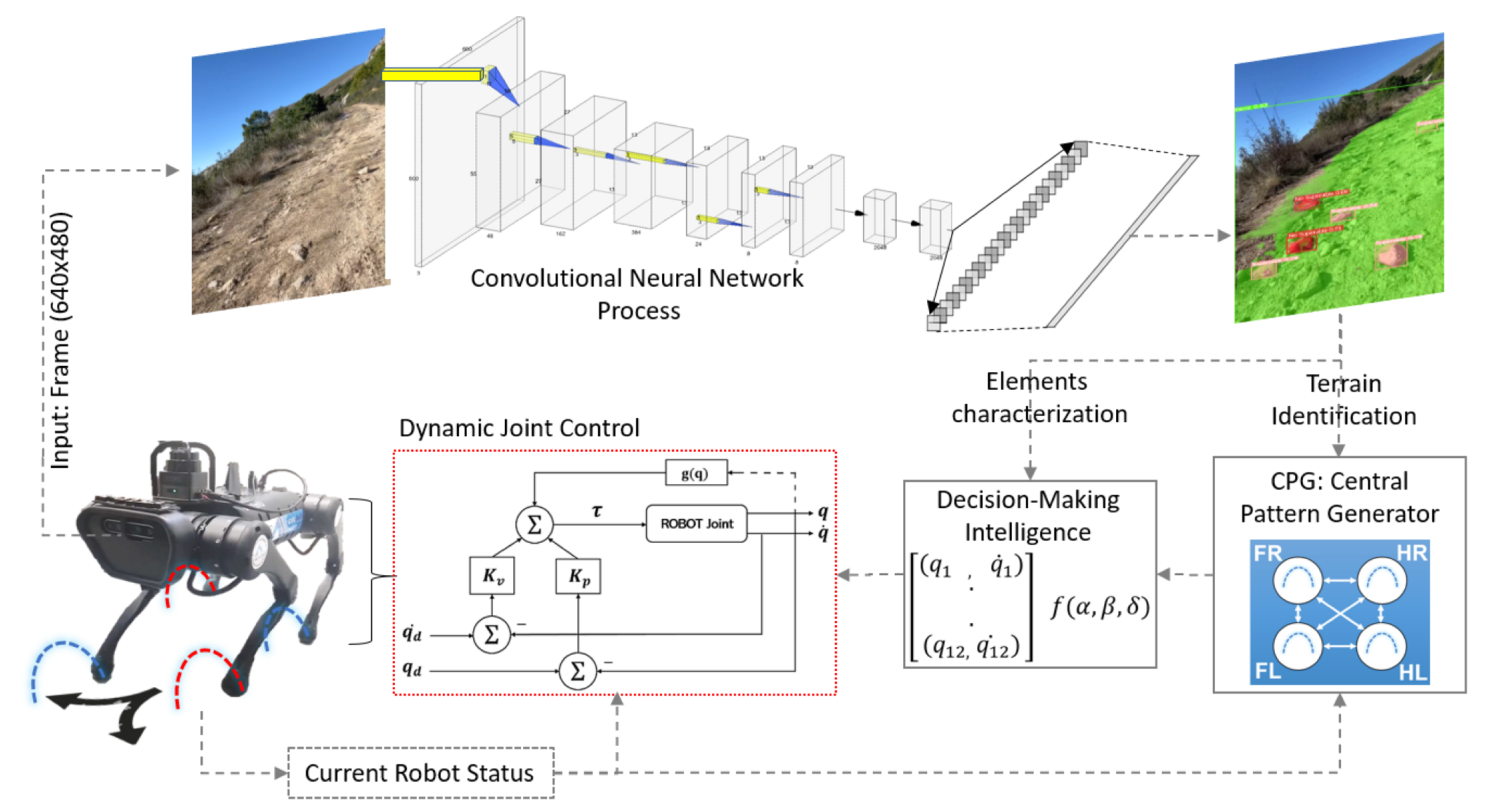
3.4. Convolutional Neural Networks for Identification and Characterization of the Environment
3.4.1. Datasets and Network Training
3.4.2. Automatic Adjustment of Patterns Based on the Neural Network Processing
| Algorithm 1 Quadruped Robots Gait Pattern Regulation |
|
4. Results
4.1. Simulation Analysis
4.2. Evaluation of Detection and Autonomous Characterization of Real Terrain
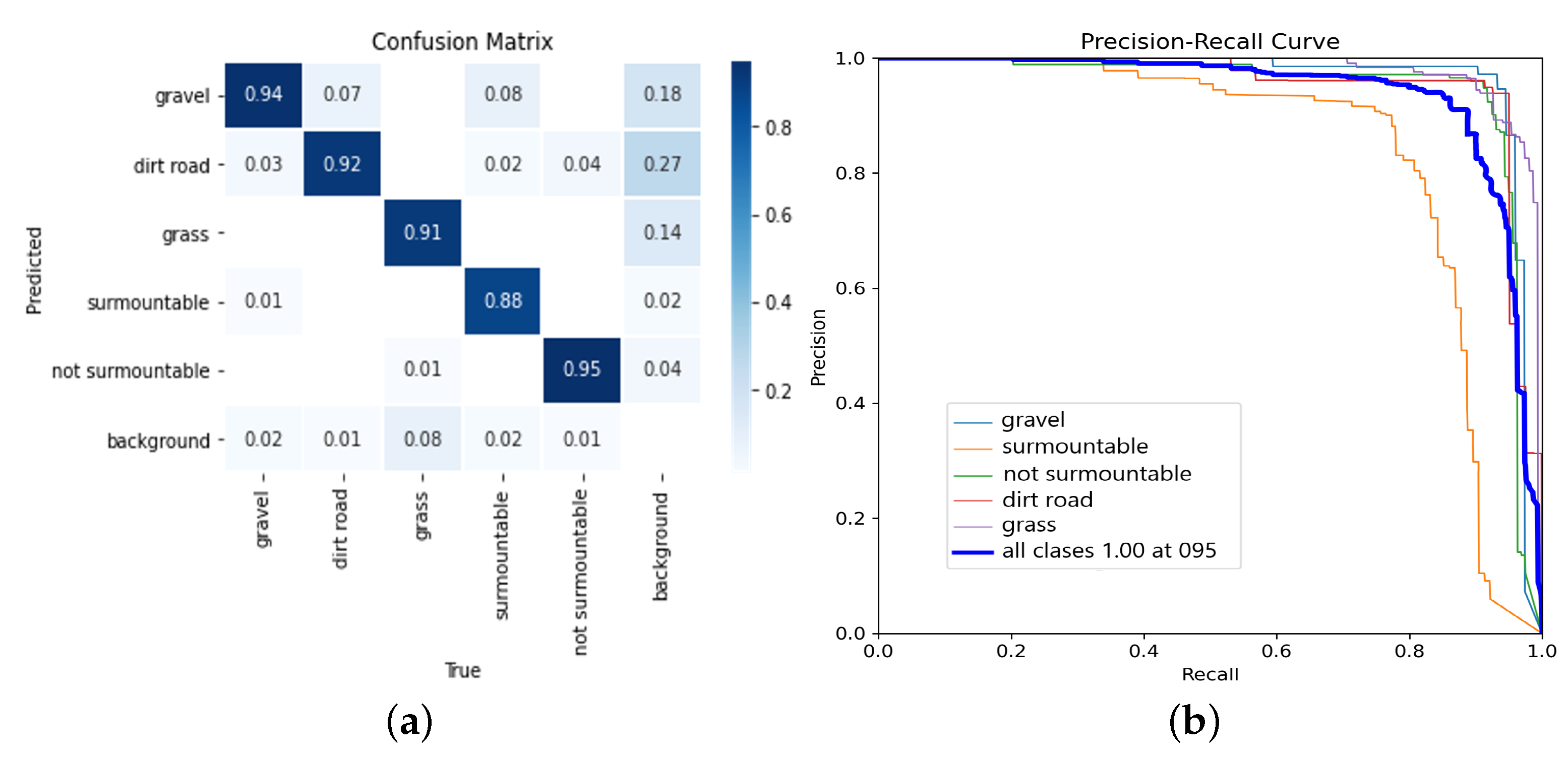
4.2.1. Analysis of the Convolutional Neural Network Efficiency
4.2.2. Evaluation of the Environment Characterization
4.2.3. Analysis of the Vision Method Regarding the State of the Art
4.3. Analysis of Results Working with the Real Robot
Comparison of Gait Pattern Adjustment Methods in the State of the Art
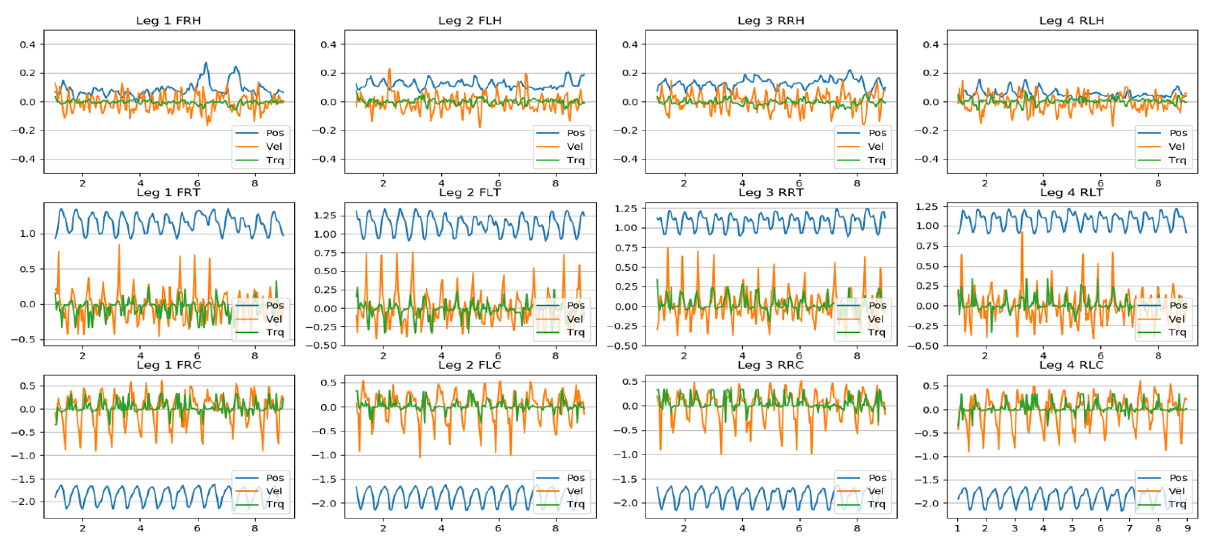
4.4. Joint Behavior
5. Conclusions
Author Contributions
Funding
Institutional Review Board Statement
Data Availability Statement
Conflicts of Interest
Abbreviations
| ARTU-R | A1 Rescue Task UPM—Robot |
| ROS | Robot Operating System |
| CNN | Convolutional Neural Netwrok |
| YOLO | You Only Look Once |
Appendix A
References
- Wang, J.; Chen, W.; Xiao, X.; Xu, Y.; Li, C.; Jia, X.; Meng, M.Q.H. A survey of the development of biomimetic intelligence and robotics. Biomim. Intell. Robot. 2021, 1, 100001. [Google Scholar] [CrossRef]
- Moro, F.L.; Spröwitz, A.; Tuleu, A.; Vespignani, M.; Tsagarakis, N.G.; Ijspeert, A.J.; Caldwell, D.G. Horse-like walking, trotting, and galloping derived from kinematic Motion Primitives (kMPs) and their application to walk/trot transitions in a compliant quadruped robot. Biol. Cybern. 2013, 107, 309–320. [Google Scholar] [CrossRef] [Green Version]
- Pettersen, K.Y. Snake robots. Annu. Rev. Control 2017, 44, 19–44. [Google Scholar] [CrossRef]
- Murphy, R.R. Disaster Robotics; MIT Press: Cambridge, MA, USA, 2014. [Google Scholar]
- Wannous, C.; Velasquez, G. United Nations Office for Disaster Risk Reduction (UNISDR)—UNISDR’s Contribution to Science and Technology for Disaster Risk Reduction and the Role of the International Consortium on Landslides (ICL). In Advancing Culture of Living with Landslides; Sassa, K., Mikoš, M., Yin, Y., Eds.; Springer International Publishing: Cham, Switzerland, 2017; pp. 109–115. [Google Scholar]
- Blackburn, M.R.; Everett, H.R.; Laird, R.T. After Action Report to the JointProgram Office: Center for the Robotic Assisted Search and Rescue (CRASAR) Related Efforts at the World Trade Center; Technical Report; Space and Naval Warfare Systems Center: San Diego, CA, USA, 2002. [Google Scholar]
- Eguchi, R.; KenElwood; Lee, E.K.; Greene, M. The 2010 Canterbury and 2011 Christchurch New Zealand Earthquakes and the 2011 Tohoku Japan Earthquake; Technical Report; Earthquake Engineering Research Institute: Berkeley, CA, USA, 2012. [Google Scholar]
- Kruijff, I.; Freda, L.; Gianni, M.; Ntouskos, V.; Hlavac, V.; Kubelka, V.; Zimmermann, E.; Surmann, H.; Dulic, K.; Rottner, W.; et al. Deployment of ground and aerial robots in earthquake-struck Amatrice in Italy (brief report). In Proceedings of the 2016 IEEE International Symposium on Safety, Security and Rescue Robotics (SSRR), Lausanne, Switzerland, 23–27 October 2016; pp. 278–279. [Google Scholar] [CrossRef]
- Whitman, J.; Zevallos, N.; Travers, M.; Choset, H. Snake Robot Urban Search After the 2017 Mexico City Earthquake. In Proceedings of the 2018 IEEE International Symposium on Safety, Security, and Rescue Robotics (SSRR), Philadelphia, PA, USA, 6–8 August 2018; pp. 1–6. [Google Scholar] [CrossRef]
- Chai, H.; Li, Y.; Song, R.; Zhang, G.; Zhang, Q.; Liu, S.; Hou, J.; Xin, Y.; Yuan, M.; Zhang, G.; et al. A survey of the development of quadruped robots: Joint configuration, dynamic locomotion control method and mobile manipulation approach. Biomim. Intell. Robot. 2022, 2, 100029. [Google Scholar] [CrossRef]
- Meng, X.; Cao, Z.; Zhang, L.; Wang, S.; Zhou, C. A slope detection method based on 3D LiDAR suitable for quadruped robots. In Proceedings of the 2016 12th World Congress on Intelligent Control and Automation (WCICA), Guilin, China, 12–15 June 2016; pp. 1398–1402. [Google Scholar] [CrossRef]
- Wu, X.A.; Huh, T.M.; Sabin, A.; Suresh, S.A.; Cutkosky, M.R. Tactile Sensing and Terrain-Based Gait Control for Small Legged Robots. IEEE Trans. Robot. 2020, 36, 15–27. [Google Scholar] [CrossRef]
- Giguere, P.; Dudek, G. A Simple Tactile Probe for Surface Identification by Mobile Robots. IEEE Trans. Robot. 2011, 27, 534–544. [Google Scholar] [CrossRef]
- Vulpi, F.; Milella, A.; Marani, R.; Reina, G. Recurrent and convolutional neural networks for deep terrain classification by autonomous robots. J. Terramech. 2021, 96, 119–131. [Google Scholar] [CrossRef]
- Walas, K. Terrain classification and negotiation with a walking robot. J. Intell. Robot. Syst. 2015, 78, 401–423. [Google Scholar] [CrossRef] [Green Version]
- Angelova, A.; Matthies, L.; Helmick, D.; Perona, P. Fast Terrain Classification Using Variable-Length Representation for Autonomous Navigation. In Proceedings of the 2007 IEEE Conference on Computer Vision and Pattern Recognition, Minneapolis, MN, USA, 17–22 June 2007; pp. 1–8. [Google Scholar] [CrossRef] [Green Version]
- Nampoothiri, M.H.; Vinayakumar, B.; Sunny, Y.; Antony, R. Recent developments in terrain identification, classification, parameter estimation for the navigation of autonomous robots. SN Appl. Sci. 2021, 3, 480. [Google Scholar] [CrossRef]
- Giguere, P.; Dudek, G. Surface identification using simple contact dynamics for mobile robots. In Proceedings of the 2009 IEEE International Conference on Robotics and Automation, Kobe, Japan, 12–17 May 2009; pp. 3301–3306. [Google Scholar] [CrossRef] [Green Version]
- Aggarwal, A.; Kirchner, F. Object Recognition and Localization: The Role of Tactile Sensors. Sensors 2014, 14, 3227–3266. [Google Scholar] [CrossRef] [Green Version]
- Schmidt, A.; Walas, K. The Classification of the Terrain by a Hexapod Robot. In Proceedings of the 8th International Conference on Computer Recognition Systems CORES 2013, Milkow, Poland, 27–29 May 2013; Burduk, R., Jackowski, K., Kurzynski, M., Wozniak, M., Zolnierek, A., Eds.; Springer International Publishing: Heidelberg, Germany, 2013; pp. 825–833. [Google Scholar]
- Brooks, C.; Iagnemma, K. Vibration-based terrain classification for planetary exploration rovers. IEEE Trans. Robot. 2005, 21, 1185–1191. [Google Scholar] [CrossRef]
- Legnemma, K.; Brooks, C.; Dubowsky, S. Visual, tactile, and vibration-based terrain analysis for planetary rovers. In Proceedings of the 2004 IEEE Aerospace Conference Proceedings (IEEE Cat. No.04TH8720), Big Sky, MT, USA, 6–13 March 2004; Volume 2, pp. 841–848. [Google Scholar] [CrossRef]
- Bai, C.; Guo, J.; Zheng, H. Three-Dimensional Vibration-Based Terrain Classification for Mobile Robots. IEEE Access 2019, 7, 63485–63492. [Google Scholar] [CrossRef]
- Gupta, S.; Girshick, R.; Arbeláez, P.; Malik, J. Learning Rich Features from RGB-D Images for Object Detection and Segmentation. In Proceedings of the Computer Vision—ECCV 2014, Zurich, Switzerland, 6–12 September 2014; Fleet, D., Pajdla, T., Schiele, B., Tuytelaars, T., Eds.; Springer International Publishing: Cham, Switzerland, 2014; pp. 345–360. [Google Scholar]
- Manduchi, R.; Castano, A.; Talukder, A.; Matthies, L. Obstacle detection and terrain classification for autonomous off-road navigation. Auton. Robot. 2005, 18, 81–102. [Google Scholar] [CrossRef] [Green Version]
- Cruz, C.; del Cerro, J.; Barrientos, A. Mixed-reality for quadruped-robotic guidance in SAR tasks. J. Comput. Des. Eng. 2023, 6. [Google Scholar] [CrossRef]
- Kırcalı, D.; Tek, F.B. Ground Plane Detection Using an RGB-D Sensor. In Information Sciences and Systems 2014, Proceedings of the 29th International Symposium on Computer and Information Sciences, Krakow, Poland, 27–28 October 2014; Czachórski, T., Gelenbe, E., Lent, R., Eds.; Springer International Publishing: Cham, Switzerland, 2014; pp. 69–77. [Google Scholar]
- Asif, U.; Bennamoun, M.; Sohel, F.A. RGB-D Object Recognition and Grasp Detection Using Hierarchical Cascaded Forests. IEEE Trans. Robot. 2017, 33, 547–564. [Google Scholar] [CrossRef] [Green Version]
- Ye, X.; Li, J.; Huang, H.; Du, L.; Zhang, X. 3D Recurrent Neural Networks with Context Fusion for Point Cloud Semantic Segmentation. In Proceedings of the European Conference on Computer Vision (ECCV), Munich, Germany, 8–14 September 2018. [Google Scholar]
- McDaniel, M.W.; Nishihata, T.; Brooks, C.A.; Iagnemma, K. Ground plane identification using LIDAR in forested environments. In Proceedings of the 2010 IEEE International Conference on Robotics and Automation, Anchorage, AK, USA, 3–7 May 2010; pp. 3831–3836. [Google Scholar] [CrossRef]
- Douillard, B.; Underwood, J.; Kuntz, N.; Vlaskine, V.; Quadros, A.; Morton, P.; Frenkel, A. On the segmentation of 3D LIDAR point clouds. In Proceedings of the 2011 IEEE International Conference on Robotics and Automation, Shanghai, China, 9–13 May 2011; pp. 2798–2805. [Google Scholar] [CrossRef]
- Pomares, A.; Martínez, J.L.; Mandow, A.; Martínez, M.A.; Morán, M.; Morales, J. Ground Extraction from 3D Lidar Point Clouds with the Classification Learner App. In Proceedings of the 2018 26th Mediterranean Conference on Control and Automation (MED), Zadar, Croatia, 19–22 June 2018; pp. 1–9. [Google Scholar] [CrossRef]
- Choi, S.; Park, J.; Byun, J.; Yu, W. Robust ground plane detection from 3D point clouds. In Proceedings of the 2014 14th International Conference on Control, Automation and Systems (ICCAS 2014), Gyeonggi-do, Republic of Korea, 22–25 October 2014; pp. 1076–1081. [Google Scholar] [CrossRef]
- Zhang, W.; Chen, Q.; Zhang, W.; He, X. Long-range terrain perception using convolutional neural networks. Neurocomputing 2018, 275, 781–787. [Google Scholar] [CrossRef]
- Wang, W.; Zhang, B.; Wu, K.; Chepinskiy, S.A.; Zhilenkov, A.A.; Chernyi, S.; Krasnov, A.Y. A visual terrain classification method for mobile robots’ navigation based on convolutional neural network and support vector machine. Trans. Inst. Meas. Control 2022, 44, 744–753. [Google Scholar] [CrossRef]
- Verbickas, R.; Whitehead, A. Sky and ground detection using convolutional neural networks. In Proceedings of the International Conference on Machine Vision and Machine Learning (MVML), Prague, Czech Republic, 14–15 August 2014; Volume 1. [Google Scholar]
- Brandão, M.; Shiguematsu, Y.M.; Hashimoto, K.; Takanishi, A. Material recognition CNNs and hierarchical planning for biped robot locomotion on slippery terrain. In Proceedings of the 2016 IEEE-RAS 16th International Conference on Humanoid Robots (Humanoids), Cancun, Mexico, 15–17 November 2016; pp. 81–88. [Google Scholar] [CrossRef] [Green Version]
- Kozlowski, P.; Walas, K. Deep neural networks for terrain recognition task. In Proceedings of the 2018 Baltic URSI Symposium (URSI), Poznan, Poland, 15–17 May 2018; pp. 283–286. [Google Scholar] [CrossRef]
- Valsecchi, G.; Grandia, R.; Hutter, M. Quadrupedal Locomotion on Uneven Terrain With Sensorized Feet. IEEE Robot. Autom. Lett. 2020, 5, 1548–1555. [Google Scholar] [CrossRef] [Green Version]
- Gehring, C.; Coros, S.; Hutter, M.; Bloesch, M.; Hoepflinger, M.A.; Siegwart, R. Control of dynamic gaits for a quadrupedal robot. In Proceedings of the 2013 IEEE International Conference on Robotics and Automation, Karlsruhe, Germany, 6–10 May 2013; pp. 3287–3292. [Google Scholar] [CrossRef] [Green Version]
- Spröwitz, A.; Tuleu, A.; Vespignani, M.; Ajallooeian, M.; Badri, E.; Ijspeert, A.J. Towards dynamic trot gait locomotion: Design, control, and experiments with Cheetah-cub, a compliant quadruped robot. Int. J. Robot. Res. 2013, 32, 932–950. [Google Scholar] [CrossRef] [Green Version]
- Chen, S.; Zhang, B.; Mueller, M.W.; Rai, A.; Sreenath, K. Learning Torque Control for Quadrupedal Locomotion. arXiv 2023, arXiv:cs.RO/2203.05194. [Google Scholar]
- Agrawal, A.; Chen, S.; Rai, A.; Sreenath, K. Vision-Aided Dynamic Quadrupedal Locomotion on Discrete Terrain Using Motion Libraries. In Proceedings of the 2022 International Conference on Robotics and Automation (ICRA), Philadelphia, PA, USA, 23–27 May 2022; pp. 4708–4714. [Google Scholar] [CrossRef]
- Meng, X.; Wang, S.; Cao, Z.; Zhang, L. A review of quadruped robots and environment perception. In Proceedings of the 2016 35th Chinese Control Conference (CCC), Chengdu, China, 27–29 July 2016; pp. 6350–6356. [Google Scholar] [CrossRef]
- Zha, F.; Chen, C.; Guo, W.; Zheng, P.; Shi, J. A free gait controller designed for a heavy load hexapod robot. Adv. Mech. Eng. 2019, 11, 1687814019838369. [Google Scholar] [CrossRef]
- Zenker, S.; Aksoy, E.E.; Goldschmidt, D.; Wörgötter, F.; Manoonpong, P. Visual terrain classification for selecting energy efficient gaits of a hexapod robot. In Proceedings of the 2013 IEEE/ASME International Conference on Advanced Intelligent Mechatronics, Wollongong, Australia, 9–12 July 2013; pp. 577–584. [Google Scholar] [CrossRef]
- Kong, B. Modeling and Algorithm Implementation of Free Gait Planning for Quadruped Robot Based on Machine Vision. In Proceedings of the 2021 International Conference on Networking, Communications and Information Technology (NetCIT), Manchester, UK, 26–27 December 2021; pp. 196–199. [Google Scholar] [CrossRef]
- Gong, Z.; Zhang, Y.; Lu, D.; Wu, T. Vision-Based Quadruped Pose Estimation and Gait Parameter Extraction Method. Electronics 2022, 11, 3702. [Google Scholar] [CrossRef]
- Chen, Z.; Li, J.; Wang, J.; Wang, S.; Zhao, J.; Li, J. Towards hybrid gait obstacle avoidance for a six wheel-legged robot with payload transportation. J. Intell. Robot. Syst. 2021, 102, 60. [Google Scholar] [CrossRef]
- Zhang, S.; Liu, M.; Yin, Y.; Rong, X.; Li, Y.; Hua, Z. Static Gait Planning Method for Quadruped Robot Walking on Unknown Rough Terrain. IEEE Access 2019, 7, 177651–177660. [Google Scholar] [CrossRef]
- Wang, J.; Lewis, M.; Gennari, J. Interactive simulation of the NIST USAR arenas. In Proceedings of the SMC’03 Conference Proceedings, 2003 IEEE International Conference on Systems, Man and Cybernetics. Conference Theme—System Security and Assurance (Cat. No.03CH37483), Washington, DC, USA, 8 October 2003; Volume 2, pp. 1327–1332. [Google Scholar] [CrossRef]
- Lambert. Papers with Code—MSEG Dataset. 2021. Available online: https://paperswithcode.com/dataset/mseg (accessed on 1 June 2023 ).
- Mortimer. Papers with Code—TAS-nir Dataset. 2022. Available online: https://paperswithcode.com/dataset/tas-nir (accessed on 1 June 2023).
- Metzger. Papers with Code—tas500 Dataset. 2021. Available online: https://paperswithcode.com/dataset/tas500 (accessed on 1 June 2023).
- Fortin. Papers with Code—timberseg 1.0 Dataset. 2022. Available online: https://paperswithcode.com/dataset/timberseg-1-0 (accessed on 1 June 2023).
- Jiang. Papers with Code—rellis-3d Dataset. 2021. Available online: https://paperswithcode.com/dataset/rellis-3d (accessed on 1 June 2023).
- Filitchkin, P.; Byl, K. Feature-based terrain classification for LittleDog. In Proceedings of the 2012 IEEE/RSJ International Conference on Intelligent Robots and Systems, Vilamoura-Algarve, Portugal, 7–12 October 2012; pp. 1387–1392. [Google Scholar] [CrossRef]
- Haddeler, G.; Yee, M.; You, Y.; Chan, J.; Adiwahono, A.H.; Yau, W.Y.; Chew, C.M. Traversability analysis with vision and terrain probing for safe legged robot navigation. arXiv 2022, arXiv:2209.00334. [Google Scholar] [CrossRef]
- Wermelinger, M.; Fankhauser, P.; Diethelm, R.; Krüsi, P.; Siegwart, R.; Hutter, M. Navigation planning for legged robots in challenging terrain. In Proceedings of the 2016 IEEE/RSJ International Conference on Intelligent Robots and Systems (IROS), Daejeon, Republic of Korea, 9–14 October 2016; pp. 1184–1189. [Google Scholar] [CrossRef] [Green Version]


| Component | Description |
|---|---|
| Unitree A1 | Quadruped Robot |
| Nvidia Jetson Xavier-Nx | On-board Embedded System |
| Real-Sense | RGB-Depth Sensor |
| MSI1660-Ti Laptop | Computer for Simulations |
| Simulation Results | |||||
|---|---|---|---|---|---|
| Scenario: | A. | B. | C. | D. | |
| Gait Patterns | Repetitions: | 30 | 30 | 30 | 30 |
| 1-3 | av. time (s) | 18.2 | 21.1 | 17.7 | 48.3 |
| % advance | 98.3 | 90.2 | 66.3 | 75.3 | |
| av. distance (m) | 3.4 | 1.9 | 2.9 | 3.9 | |
| 2-2 alternate | av. time (s) | 14.2 | 10.2 | 16.3 | 17.4 |
| % advance | 98.4 | 98.1 | 73.2 | 81.5 | |
| av. distance (m) | 3.3 | 2.1 | 2.41 | 4.41 | |
| 2-2 gallop | av. time (s) | 25.1 | 9.2 | 14.6 | 13.6 |
| % advance | 81.4 | 54.4 | 64.1 | 75.5 | |
| av. distance (m) | 2.3 | 2.1 | 2.41 | 3.41 | |
| Work | Terrain ID | Obstacle ID | Benchmark Test | Sensor | Tested on Robots | Semantic Segmentation |
|---|---|---|---|---|---|---|
| [35] | ✓ | X | X | RGB | X | X |
| [14] | ✓ | X | ✓ | RGB-D | ✓ | X |
| [34] | ✓ | X | ✓ | RGB | X | ✓ |
| [36] | ✓ | X | X | RGB | X | ✓ |
| [15] | ✓ | X | X | RGB-D | ✓ | X |
| [46] | ✓ | X | ✓ | RGB | ✓ | X |
| [16] | ✓ | X | X | RGB | X | X |
| [37] | ✓ | X | X | RGB-D | ✓ | ✓ |
| [57] | ✓ | X | X | RGB | ✓ | ✓ |
| [25] | X | ✓ | X | stereo camera | ✓ | X |
| [38] | ✓ | X | X | RGB | X | ✓ |
| Authors | ✓ | ✓ | ✓ | RGB-D | ✓ | ✓ |
| Scenery | Dirt Road | Compact Soil | Gravel | Grass |
|---|---|---|---|---|
| Number of Tests | 15 | 12 | 12 | 12 |
| Mean speed | 0.09 m/s | 0.11 m/s | 0.11 m/s | 0.12 m/s |
| Mean time | 20.1 s | 17.1 s | 17.7 s | 16.3 s |
| Average body height | 23.1 cm | 23.2 cm | 22.1 cm | 22.9 cm |
| Average step height (A) | 14.7 cm | 13.2 cm | 14.7 cm | 12.6 cm |
| Average step length (h) | 6.5 cm | 7.0 cm | 7.1 cm | 6.8 cm |
| Completion success rate | 89% | 91% | 89% | 93% |
| Scenery | Dirt Road | Compact Soil | Gravel | Grass |
|---|---|---|---|---|
| Number of tests | 15 | 15 | 15 | 10 |
| Mean speed | 0.19 m/s | 0.23 m/s | 0.2 m/s | 0.19 m/s |
| Mean time | 10.2 s | 8.5 s | 9.7 s | 10.2 s |
| Average body height | 25.6 cm | 25.3 cm | 23.1 cm | 24.4 cm |
| Average step height (A) | 10.7 cm | 8.4 cm | 10.7 cm | 9.3 cm |
| Average step length (h) | 7.3 cm | 8.1 cm | 9.1 cm | 7.9 cm |
| Completion success rate | 94% | 100% | 93% | 100% |
| Work | Robot | Visual Terr. Det. | Visual Obst Det. | Pattern | Test Real/Sim |
|---|---|---|---|---|---|
| [40] | Quadruped | X | X | 2-2/3-1 | Real |
| [45] | Hexapod | X | X | alternate tripod | Sim |
| [47] | Quadruped | X | X | 2-2 | Study |
| [15] | Spider | ✓ | X | alternate pairs | Real |
| [46] | Spider | ✓ | X | tripod | Real |
| [12] | Hexapod | X | X | tripod | Real |
| [48] | - | X | X | pattern extraction | Real |
| [49] | wheel-legged | X | ✓ | hybrid | Real |
| [50] | Quadruped | X | X | 2-2 | Sim |
| [43] | Quadruped | X | ✓ | 2-2 | Real |
| Authors | Quadruped | ✓ | ✓ | 2-2/3-1 | Real/Sim |
| Joint Nomenclature | |||||
|---|---|---|---|---|---|
| 1. F | Front | 2. R | Right | 3. H | Hip |
| 3. T | Thigh | ||||
| 1. R | Rear | 2. L | Left | ||
| 3. C | Calf | ||||
Disclaimer/Publisher’s Note: The statements, opinions and data contained in all publications are solely those of the individual author(s) and contributor(s) and not of MDPI and/or the editor(s). MDPI and/or the editor(s) disclaim responsibility for any injury to people or property resulting from any ideas, methods, instructions or products referred to in the content. |
© 2023 by the authors. Licensee MDPI, Basel, Switzerland. This article is an open access article distributed under the terms and conditions of the Creative Commons Attribution (CC BY) license (https://creativecommons.org/licenses/by/4.0/).
Share and Cite
Cruz Ulloa, C.; Sánchez, L.; Del Cerro, J.; Barrientos, A. Deep Learning Vision System for Quadruped Robot Gait Pattern Regulation. Biomimetics 2023, 8, 289. https://doi.org/10.3390/biomimetics8030289
Cruz Ulloa C, Sánchez L, Del Cerro J, Barrientos A. Deep Learning Vision System for Quadruped Robot Gait Pattern Regulation. Biomimetics. 2023; 8(3):289. https://doi.org/10.3390/biomimetics8030289
Chicago/Turabian StyleCruz Ulloa, Christyan, Lourdes Sánchez, Jaime Del Cerro, and Antonio Barrientos. 2023. "Deep Learning Vision System for Quadruped Robot Gait Pattern Regulation" Biomimetics 8, no. 3: 289. https://doi.org/10.3390/biomimetics8030289